
Abstract
Automatic tool selection in milling operation has become a very important step in the manufacturing and planning processes for 2.5D piece machining. The main contribution of this article is the development of a new method based on directional morphological approaches, applied to automatic tool selection in computer numerical control milling machines for machining a 2.5D of a geometry piece provided of three-dimensional model of computer-aided design or from an image taken with other devices. First, the image is preprocessed by applying several image processing techniques. Later, mathematical morphology as erosion or dilation to create structural element with the shape of the cutting tool is used. The method displaces a structural element throughout the entire image with the values of the lengths of the piece boundary and the cutting tool to select the correct cutting tool and tool path. Besides, with the same structural element, the zig and zig-zag contour trajectories are obtained in standard computer numerical control code. Results from these experiments show that the method makes it possible to obtain good performance in automatic tool selection when several types of pieces are processed.
Introduction
In the manufacturing process area, the demand for better productivity with high quality has been constant. For the next generation of computer numerical control (CNC) machines, topics with the following themes should be taken into account to develop commercial computer-aided manufacturing (CAM) and the development of a system capable of recognizing complex features, among others: total error compensation, concepts of autonomous manufacturing and process condition monitoring. 1 Some research contributions on these themes were carried out by Rodriguez-Donate et al. 2 and Eladawi et al. 3 Otherwise, a large percentage of pieces used in the industry have a shape of contours where the base face is a plane surface denominated 2.5 axis. A 2.5D solid model can be defined as a cut with a series of two-dimensional (2D) tool paths at different Z slices of a three-dimensional (3D) solid model. Similarly, automatic tool selection in milling operation is one of the most important steps in process planning; moreover, at present, CAM software transfers this task to the worker who does it based on its own experience, ability and knowledge. Considerable studies have reported about the variables that affect the milling process such as material piece selection, 4 cutting conditions,5,6 tool materials, 4 tool sequence, 7 cutting fluid selection, 4 tool path, 3 control, 8 identification 9 and tool selection. 10
Tool selection, a task commonly made by a human operator, is an important aspect in machining processes, since if the tool selected is incorrect, it can produce dimensional errors in workpiece, such as possible crashes, consequently leading to rejection of the piece. In this regard, some methods have been developed for tool selection in milling processes in pockets of 2.5D as described in the work by Ahmed et al., 7 in which an optimization algorithm based on analytical methods was proposed for formulation of the tool sequence selection problem, obtaining good results with the support of a computer-aided design (CAD) software. Another method is that proposed by Lim et al. 11 who used experimental algorithms using mathematical Boolean to determine the optimal set of tools in pockets with the integration of CAD/CAM. In this way, Ramaswami et al. 10 developed an algorithm for decomposing polygons into convex areas using dynamic programming. The above-mentioned research uses complex algorithms and certain human intervention is still necessary. Another approach for tool selection is based on the shape but it has not been widely studied; this method is important because it eliminates the designer subjective decisions, does not require previous knowledge, does not use complex mathematical models and is easy to implement. For such reasons, it is desirable to develop an approach to make tool selection in milling based on the shape, automatically.
On the contrary, morphology is a method that removes or adds pixels from a binary image formed by a set called structural element: the morphology applied on image processing has been widely used in applications in which an opening operation is introduced for monitoring various defects occurring on chenille yarns according to Maros et al.; 12 the cutting condition effects as roughness presented by Sarma et al., 5 the prediction of cutting conditions by Gadelmawla et al. 6 and path generation are included for milling CNC machines by Eladawi et al. 3
The novelty of this research is a new method based on directional morphological approaches from image processing, applied to automatic tool selection in CNC milling machine, showing an easy way to simulate pieces, eliminating the designer subjective decisions, reducing tool selection mistakes, making the selection process and design faster, and in addition, it does not require a priori knowledge in operations such as pocket, mill, mill thread, helicoidal mill, extrusion, profile and section, fillet, chamfer and mill thread.
Background
Automatic tool selection has been a successful profitable method for reducing the machining time, errors in process, human interaction and costs; improving product quality13,14 and creating new methods by the extensive use of CNC machines in the industry. In this article, the method for automatic tool selection begins by extracting the 3D model provided by either a .DXF file (drawing exchange format) or from an image taken with other devices; the DXF file format is used because of easy availability and low cost in terms of computational work. Tufoi et al. 15 define DXF file format as information in an ASCII text file with .dxf extension, and Chung and Peng 16 show the organization section of a DXF file. After obtaining the DXF file in order to diminish the possible error in boundary, it was used to compare and correct when an image (BMP file) is used. Finally, mathematical morphology is applied to generate automatic tool selection. The image processing techniques, solid models and other systems used are given in the following:
Morphological operations. These are defined as an edge filter of the piece, satisfying properties such as translation invariance, anti-extensivity, monotonic increases and idempotence; 17 among the methods, more common methods of mathematical morphology on image processing are erosion and dilation. These methods remove or add pixels from a binary image according to rules that depend on the pattern of the neighboring pixels formed by the interaction of a set called structuring element with a set of pixels inside the image; the erosion operation reduces the size of an image, while the dilation operation enlarges its geometric size. 18
Binary image. The value of each pixel in the image is changed to a binary logic number; thresholding is the most applied method to convert a gray-scale image
Directional vectors of the piece. The gradient of edge is very important for image analysis, and it is widely used for acquisition, registration, identification, segmentation and compression of object in scene15,19 to obtain the edge; the Sobel operator is used because of its low sensitivity to noise and low cost in terms of computational work.
Extracting piece. The method of sequential algorithm and scan mask by Jing et al 20 are more commonly applied and used to register images.
Software CAD–CAM–CAE. CAD, CAM and computer-aided engineering (CAE) are systems which graphic, design and simulate respectively facilities the user to do the tasks.14,15,21
2D, 2.5D and 3D models. The graphics in this article are 2D and 2.5D models, in which a 2D solid model is an X–Y shape extruded in Z, an example is a circle and a rectangle in 2D model extruded in Z, which produces a cylinder and cuboid in 3D solid, respectively, while a 2.5D solid model can be a cut with a series of 2D tool paths at different Z slices, which produce analytic shapes (lines and circles). 22
Structural elements. The length of the cutting tool is created by the structural element; the tools in this research, data handbook and catalogs of tool manufacturers were used to select the proper tool for milling operations.
Otherwise, the work by Bithika and Datta 17 applies mathematical morphology to detect manufacturing defects. This work is an example of the application of image processing to detect manufacturing defects. Such techniques are used to measure the effect of cutting speed on the surface roughness, as in another example presented by Sarma et al., 5 which provides a new strategy in manufacturing.
Methodology
The application of mathematical morphology to solve manufacturing problems is a new approach in the literature. In this article, six steps to get the automatic tool selection using morphological operations are proposed. In this way, the original file is a 3D model taken from CAD and exported to a DXF file; then by applying a transformation 16 into the DXF file an image of BMP format is built. After applying several image preprocessing techniques such as binary image, registration, identification, segmentation and image compression for generating the contour of the piece, and using the boundary of it and applying image processing such as gradient and labeling perimeter of the piece for generating the longitudes of boundary as to locating and separating the image of the piece. Finally, structural element with the shape of the cutting tool is displaced through the entire image with the lengths of the piece boundary and the cutting tool, using mathematical morphology, especially erosion or dilation to generate automatic tool selection and tool path. The DXF file was used in order to diminish the possible error in obtaining the boundary, and also to compare and correct it when an image is utilized. Figure 1 shows the detailed steps for automatic tool selection based on the shape, and each step is detailed in the following.
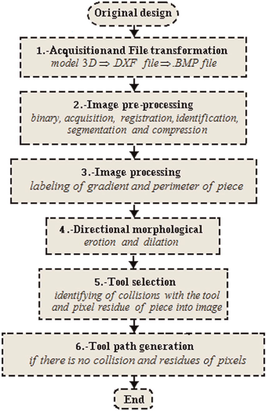
General diagram of the automatic cutting tool selection.
Step 1: acquisition and file transformation
Acquisition of DXF file
The original design (Figure 2(a)) is obtained from CAD or from an image taken with other devices, and then the upper profile model is converted into DXF file 23 (Figure 2(b)). This file contains general information about the drawing, definitions of items and the entities that make up each block.
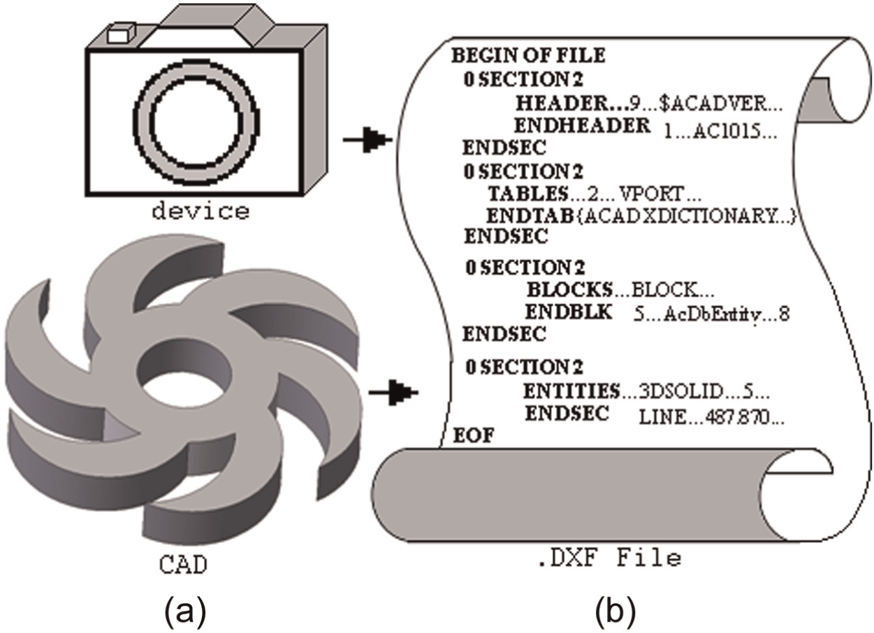
Original files: (a) design from CAD or camera and (b) DXF file.
File transformation
A precision analysis is performed, before and after applying image processing techniques, to find the most appropriate resolution according to the dimensions of the pieces to be machined (test pattern used 25.400 mm) and cutting tools (pattern test used 19.049 mm). The calibration value is also the resolution of this system, and it is approximately 1 µm, using a resolution of this system for 1 mm2 in 800 × 600 (scale 4:3, 15 × 11 pixels) and 50,800 × 50,800 (scale 1:1, 1000 × 1000 pixels).
A method of data extraction16,23 is applied to convert the DXF file into BMP file, as shown in Figure 3(a) and (b). The same distance is then automatically determined in pixels in the image, and a calibration value is obtained by dividing the distance in millimeters (
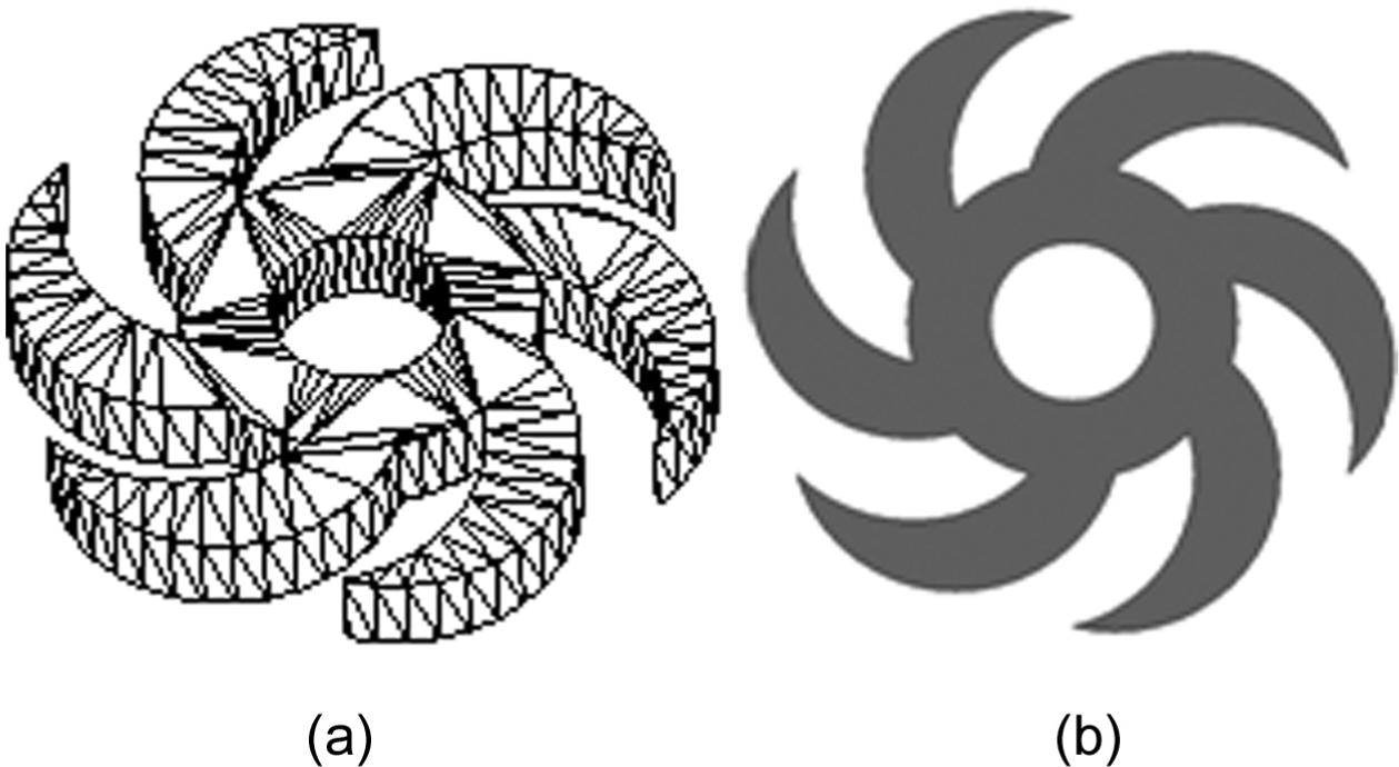
Files: (a) design without texture (wire file) and (b) image (BMP file).
Step 2: image preprocessing
Binary image
A binary image (
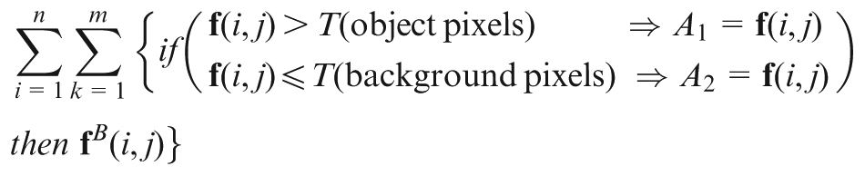
where
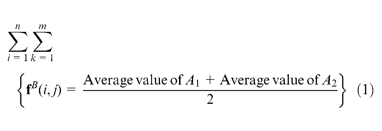
where
Step 3: image processing
Detection and labeling of the gradient and perimeter in the edge of the piece
The following step is the binary label, or limitation, of the piece
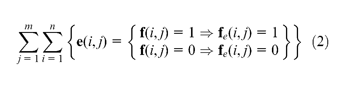
where
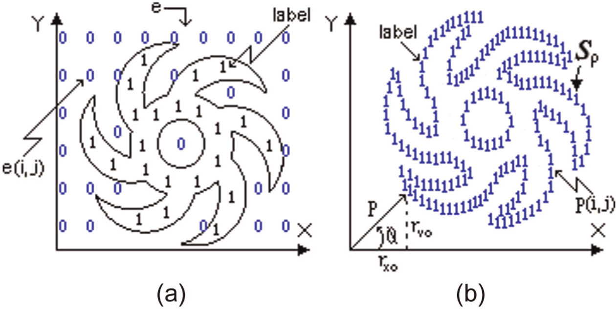
Labeling definition: (a) labeling of piece and (b) labeling of perimeter
Perimeter of the piece
The perimeter (
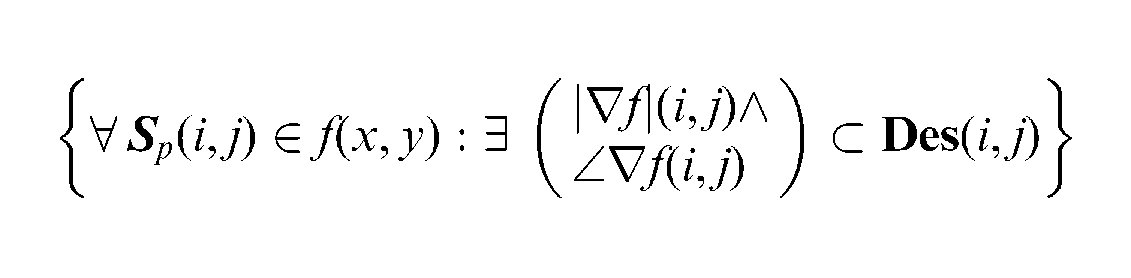
Boundary or edge of the piece
The boundary (
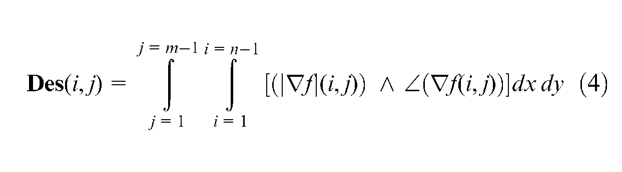
A transformation (
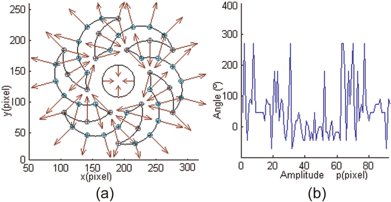
Vectors of piece: (a) direction vector of piece and (b) magnitude of edge direction.
The magnitude (
Therefore
Step 4: directional morphological approaches
Directional morphological approaches to generate size of tool
Erosion and dilation are operators to generate directional morphology in image processing, defined for binary images, to gray-scale images and to complete lattices, dilation (
Figure 6 shows the dilation of a gray-level image
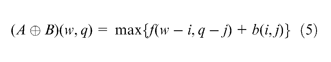
such that
Directional morphology: (a) tool size dilation and (b) tool path dilation.
Defined by
Equivalently
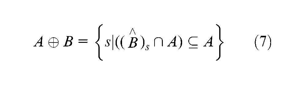
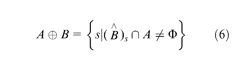
Dilation joins the translations of a picture for each pixel external to internal of an image B, called structural element as
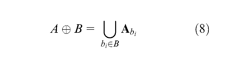
Therefore
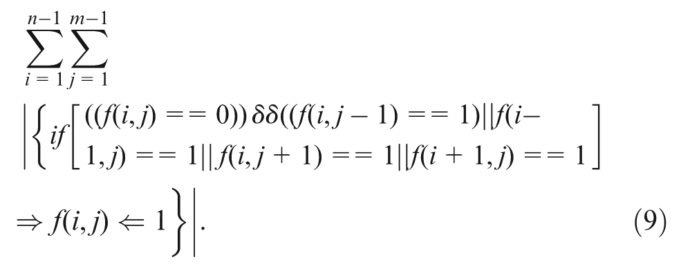
Figure 7 shows the erosion of gray levels and is defined as equation (10)
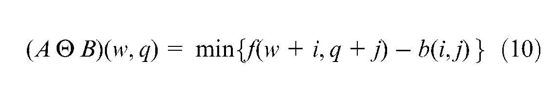
such that
Directional morphology: (a) tool size erosion and (b) tool path erosion.
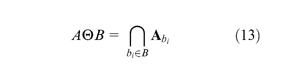
Or, it is also written as the following equations (equations (11) and (12))
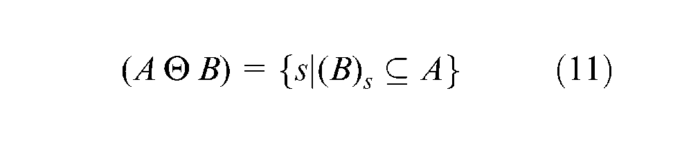
Erosion is a reverse operation to the dilation
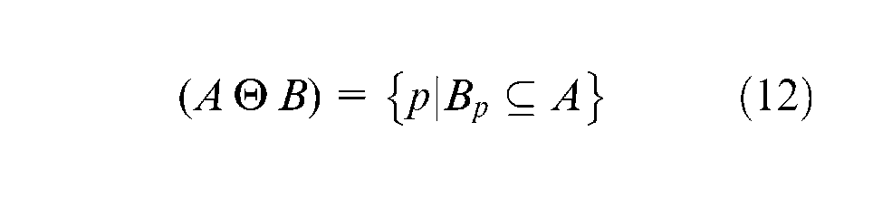
Erosion joins the translations of a picture for each pixel internal to external of an image B, called structural element as
Therefore
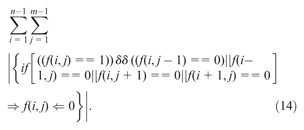
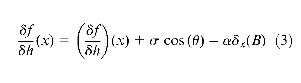
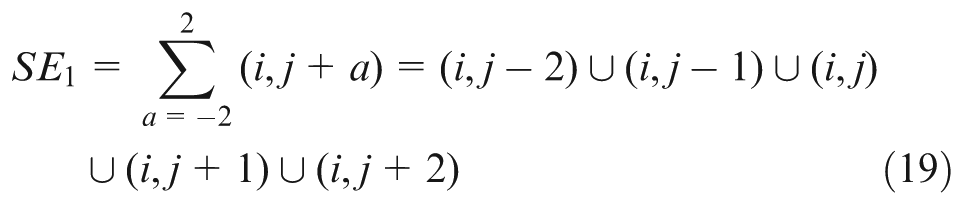
Because equations (9) and (14) of directional morphological approaches have been modified to generate the structural element of insert and tool path using the workspace boundaries, edge and the perimeter function of the piece yield equation (18) and the results are provided in Figures (7) and (8)
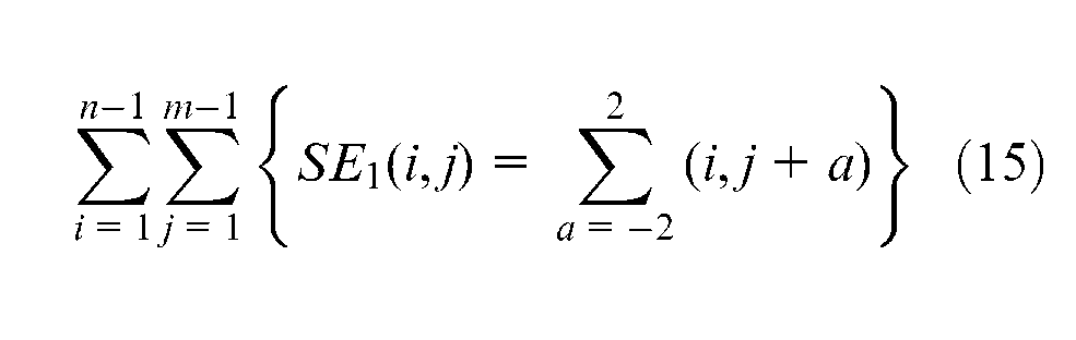
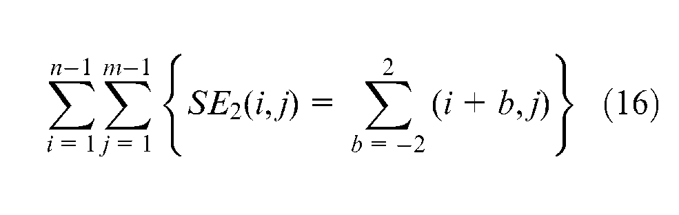
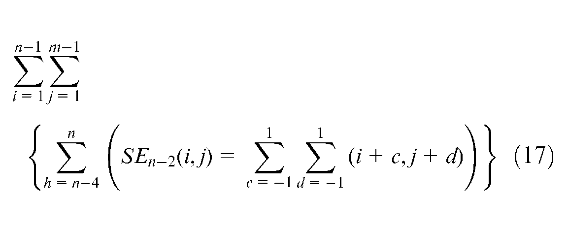
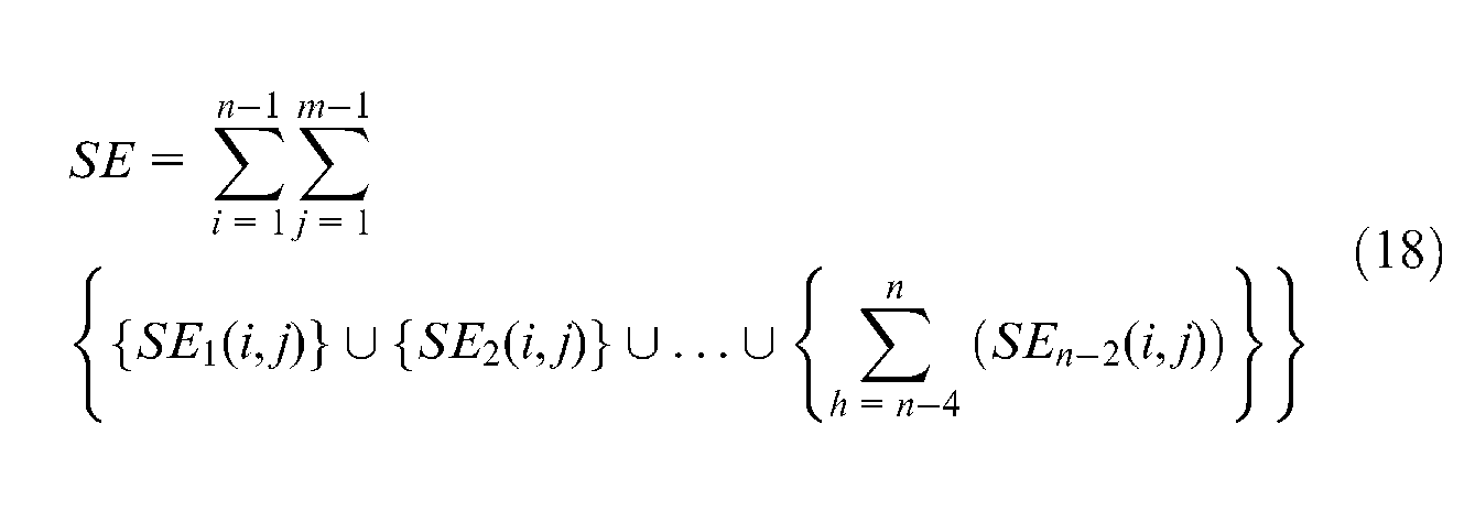
where
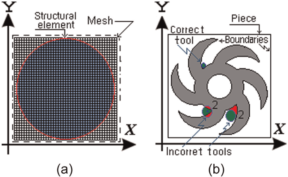
Tool selection: (a) structural element and (b) incorrect tool and correct tool.
Step 5: tool selection
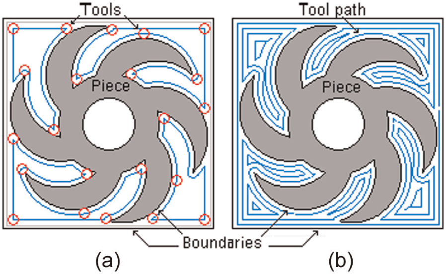
During the cutting operation, it is necessary to consider possible crashes with different machine tool elements such as the spindle, tool holders in the turret, tailstock and so on. These elements limit the workspace and should be taken into account. However, in this investigation, the workpiece, the cutting tool and tool holder are only studied; since the whole workspace requires a deep study for its determination and depends on each machine structure, it will also require more processing time and screen resolution. The direction of the edge allows selecting the type, size and tool path of the insert, which is represented by structural element in the image processing piece. When a pixel of the edge crashes a pixel of the structural element (SE), an iterative method is applied using morphology, and the structural element is moved through the perimeter function to generate the tool and tool path.
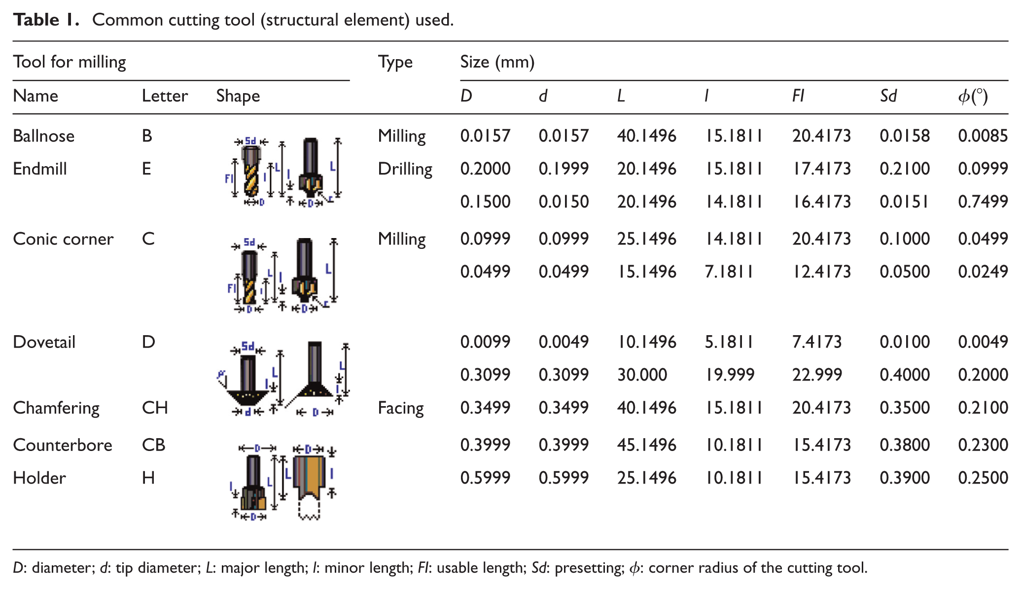
Table 1 illustrates the common types of cutting tools used in milling operations: ballnose (B), endmill (E), conic corner (C), dovetail (D), chamfering (CH), counterbore (CB) and holder (H), for milling, drilling and facing operation; the tools are generated from handbooks and tools are stored in the warehouse; the data (diameter, tip diameter, major length, minor length, usable length, presetting and corner radius of the tool) are introduced into the software for converting these data into structural elements (in pixels), as shown in Figure 8(a). For example, the cutting tools have been drawn with a mesh of 42 × 42 pixels, although a real insert as the drilling cutting tool with a diameter of 5.56 mm (
Common cutting tool (structural element) used.
To identify the most suitable cutting tool, a structural element (see Table 1) is moved through the perimeter function by applying the morphology in the direction of edge pixel of piece to select the correct tool.
When the structural element is moved through the image and then the edge gets a value (
where
Algorithm for automatic tool selection based on residues of pixels.
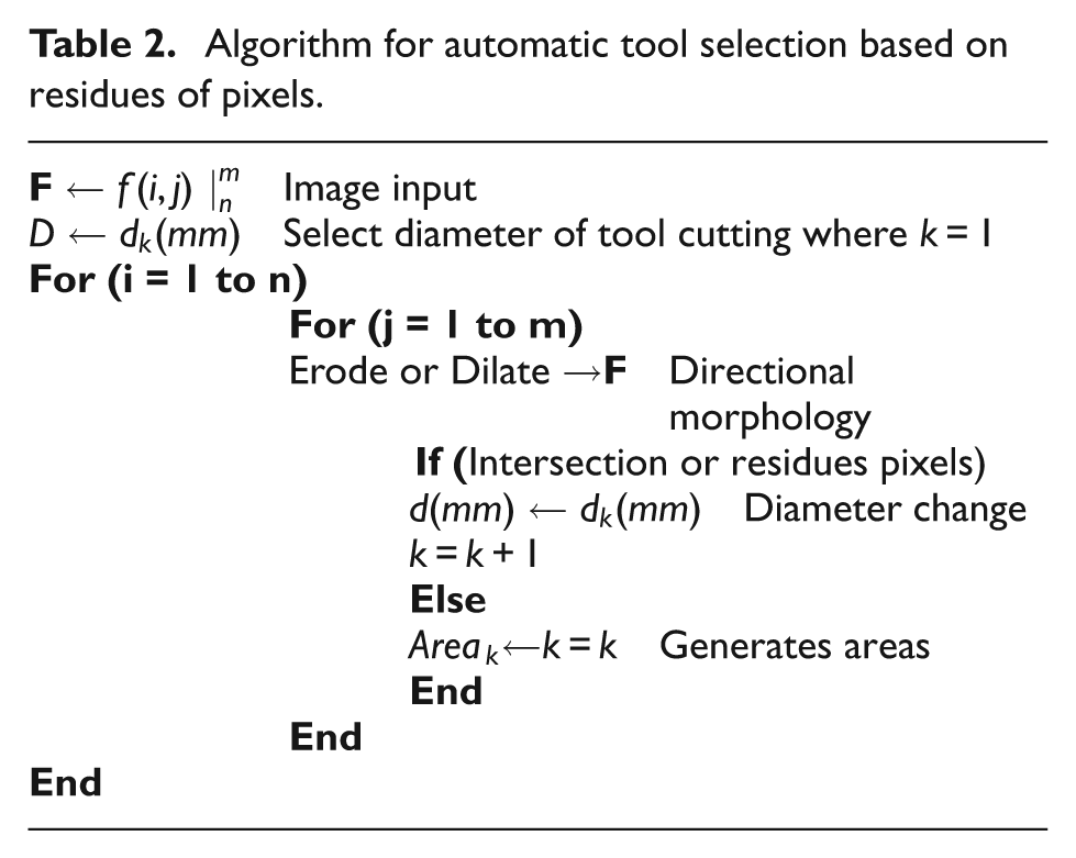
The procedure of intersection of the cutting tool with piece is checked using image processing techniques with the own software (it was developed in Microsoft Visual C++ 2010). All pixels contained in the piece are labeled in coordinates (
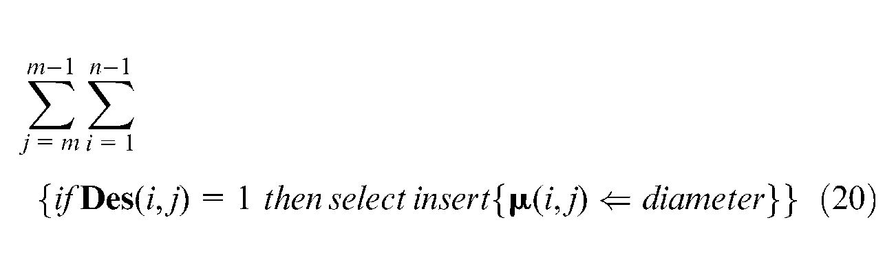
After the correct holders 28 and inserts have been selected to work in each area, many changes of cutting tools are probably required. The number of changes can be reduced by ordering the changes with the next procedure
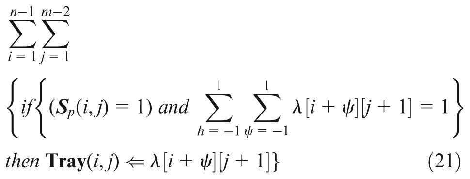
where
Step 6: tool path generation strategy
The methods of trajectory generation are zig (one way), zig-zag (two ways), zig with contour, zig-zag with contour, follow-periphery, trochoidal and profile.
29
In this article, the zig and zig with contour are used because of easy generation of trajectories. Here, it is important to clarify that path generation is only for rough cutting. The first machining is presented in Figure 9; the strategy is lineal zig where the label “1” represents an area with a tool of diameter of 0.2000 mm. The tool path is obtained by an algorithm
25
(zig) according to; a structural element with the shape of the cutting tool with diameter
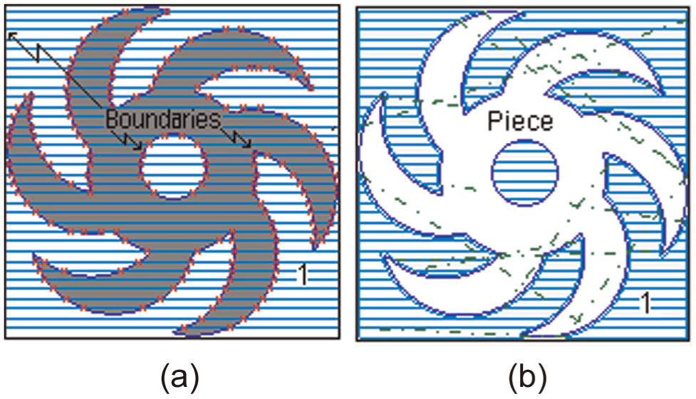
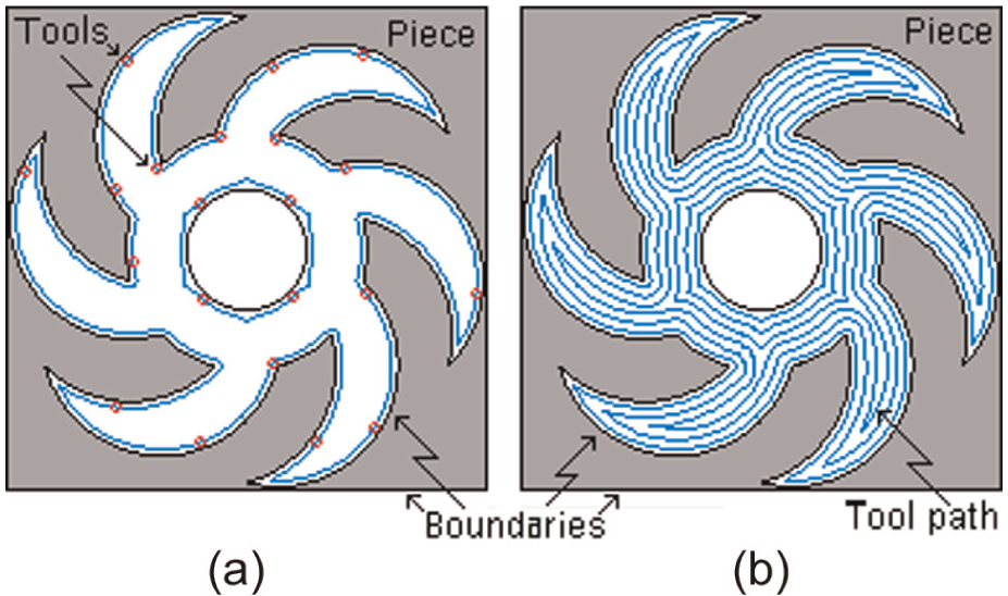
Tool selection (final piece): (a) boundaries identification and (b) rough milling (zig).
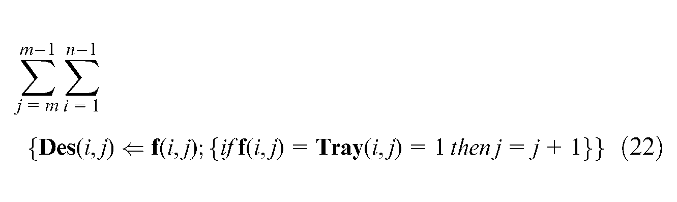
On any image, if a fix
Results and discussion
With the aim to validate the proposed methodology, three different pieces were processed to automatically select the correct tool for its machining, including operations such as pocket, mill, mill thread, helicoidal mill, extrusion, profile and section, fillet, chamfer and mill thread, and for rough mill and finish mill.
Aiming at improving accuracy, the dimensions obtained from image processing are compared with the dimensions obtained from the DXF file. With the proposed method, an image can be directly taken from a photograph camera or some other device for automatic tool selection.
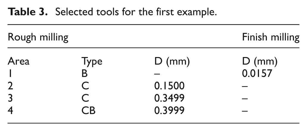
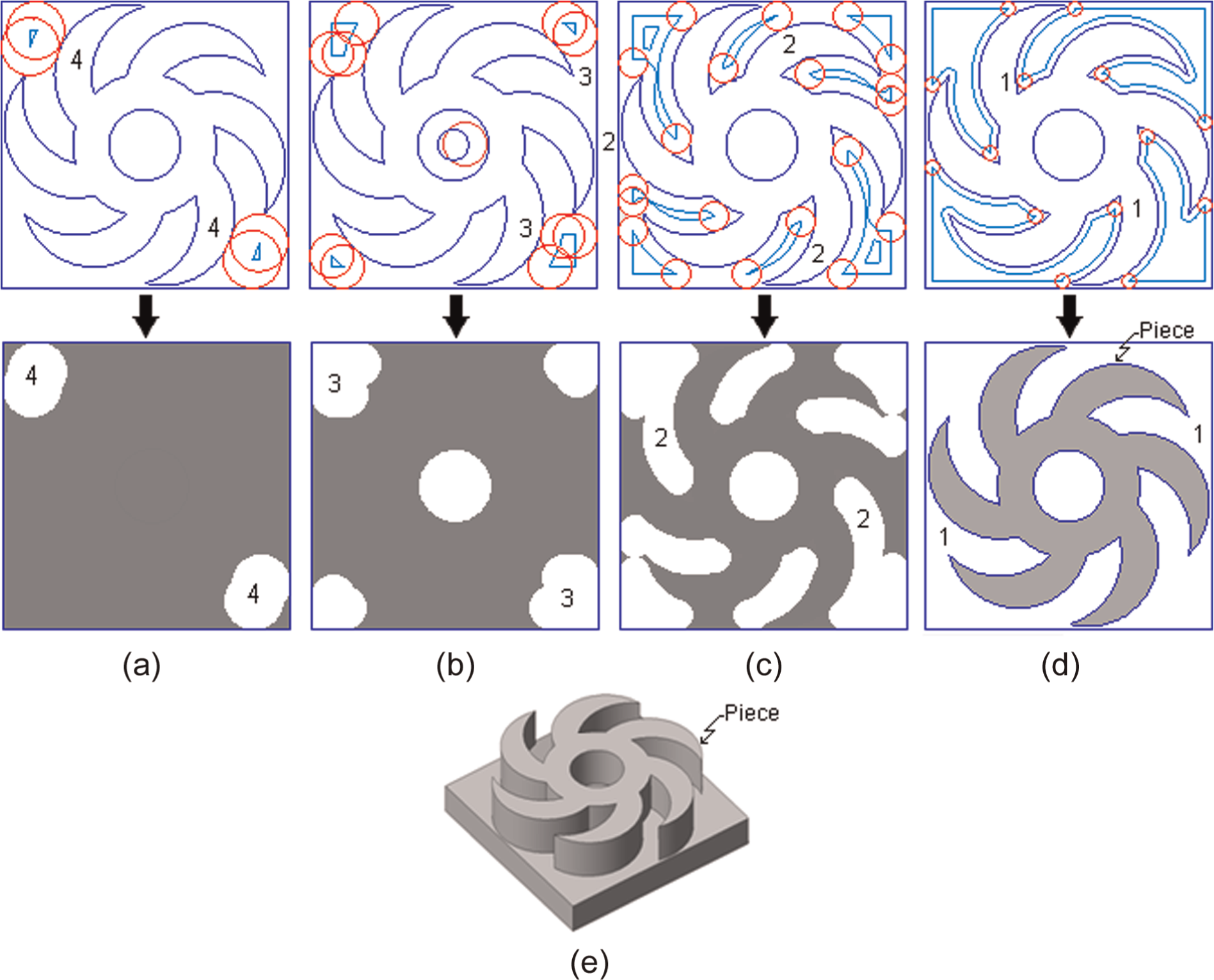
First, Figure 10 shows four different stages that automatically generate the proposed method (four different tools were selected) to obtain the piece of a pocket in zig-zag with contour. The dilation is used in this piece because the surface to remove is external to the desired geometry. Figure 10(a) depicts a contour of the piece and its respective machining approximation using a CB tool whose machined area is marked with label “4.”Figure 10(b) shows the contour and a machining approximation with a C tool, whose machined area is marked with label “3.”Figure 10(c) shows the machined area marked with label “2.” In this way, the piece finally machined with a B tool is shown in Figure 10(d). Figure 10(e) depicts the final workpiece obtained. In Table 3, parameters of cutting tool selected by the proposed method can be seen.
Selected tools for the first example.
Tool selection for first piece based on residues of pixels
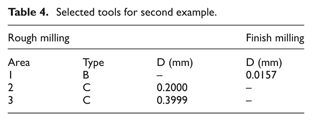
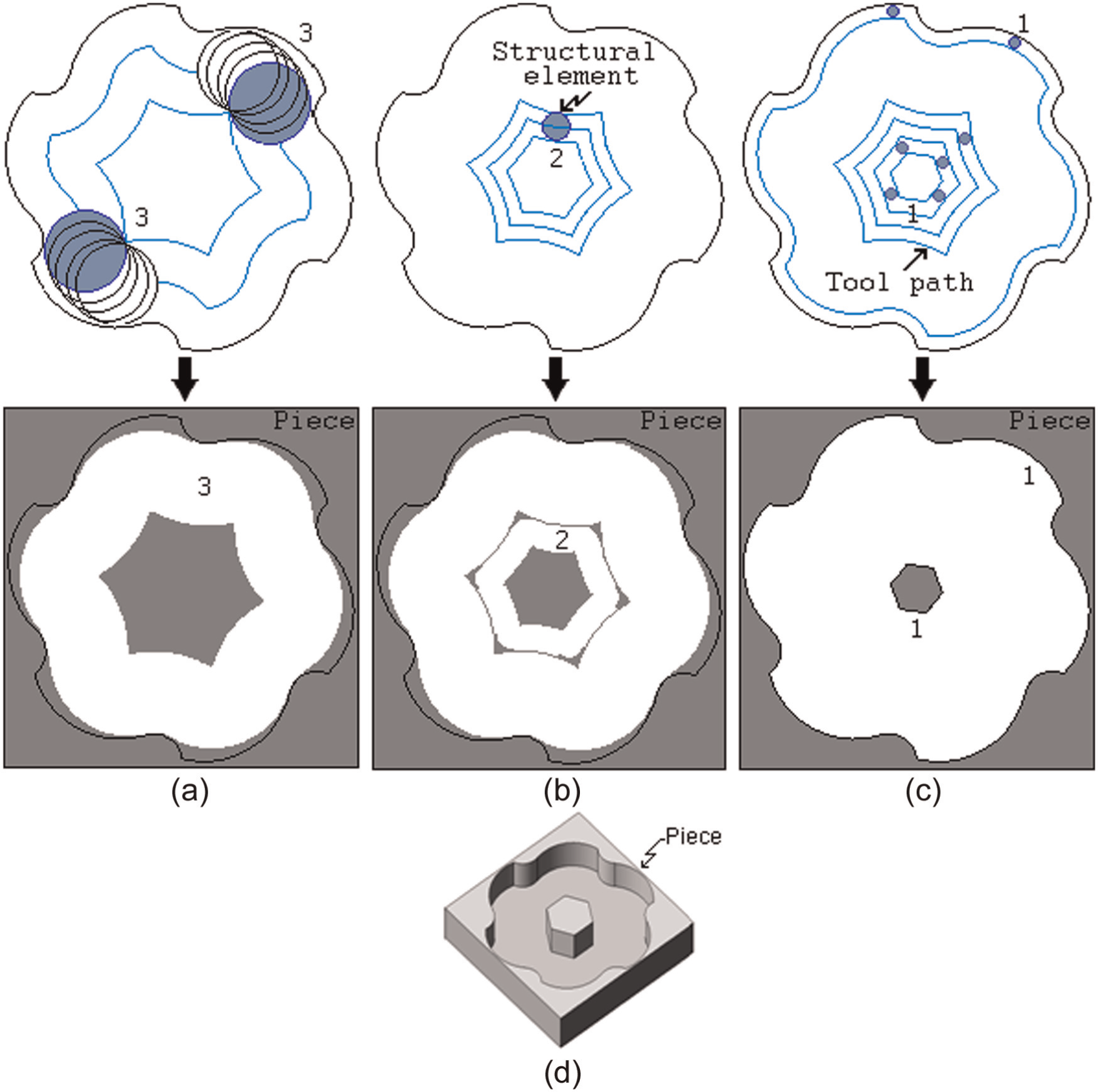
The second piece is shown in Figure 11. In this case, the piece is machined using zig-zag with contour and boundaries. An erosion operation, to select the tool automatically, is applied because the surface to remove the pixels is internal to the desired geometry. The three contours and approximations of machining with different tools marked with labels “3,”“2” and “1” are depicted in Figure 11(a)–(c), respectively. Finally, Figure 11(d) depicts the machined piece. Table 4 shows the parameters of the three different tools selected by the method.
Selected tools for second example.
Tool selection for second piece using zig-zag with contour.
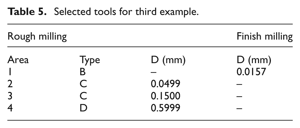
Finally, Figure 12 describes the third example, machined with rough mill using zig with contour. For automatically selecting the tool, erosion is used according to the geometry of the piece. As Table 5 shows, the rough milling uses tools C, C and D with areas marked with labels “2,”“3” and “4,” respectively. The finish milling uses a B tool with area marked with label “1.” The rough milling is made in Figure 12(a)–(c) with respective tools selected. Figure 12(d) shows the finish milling and Figure 12(e) shows the final piece.
Selected tools for third example.
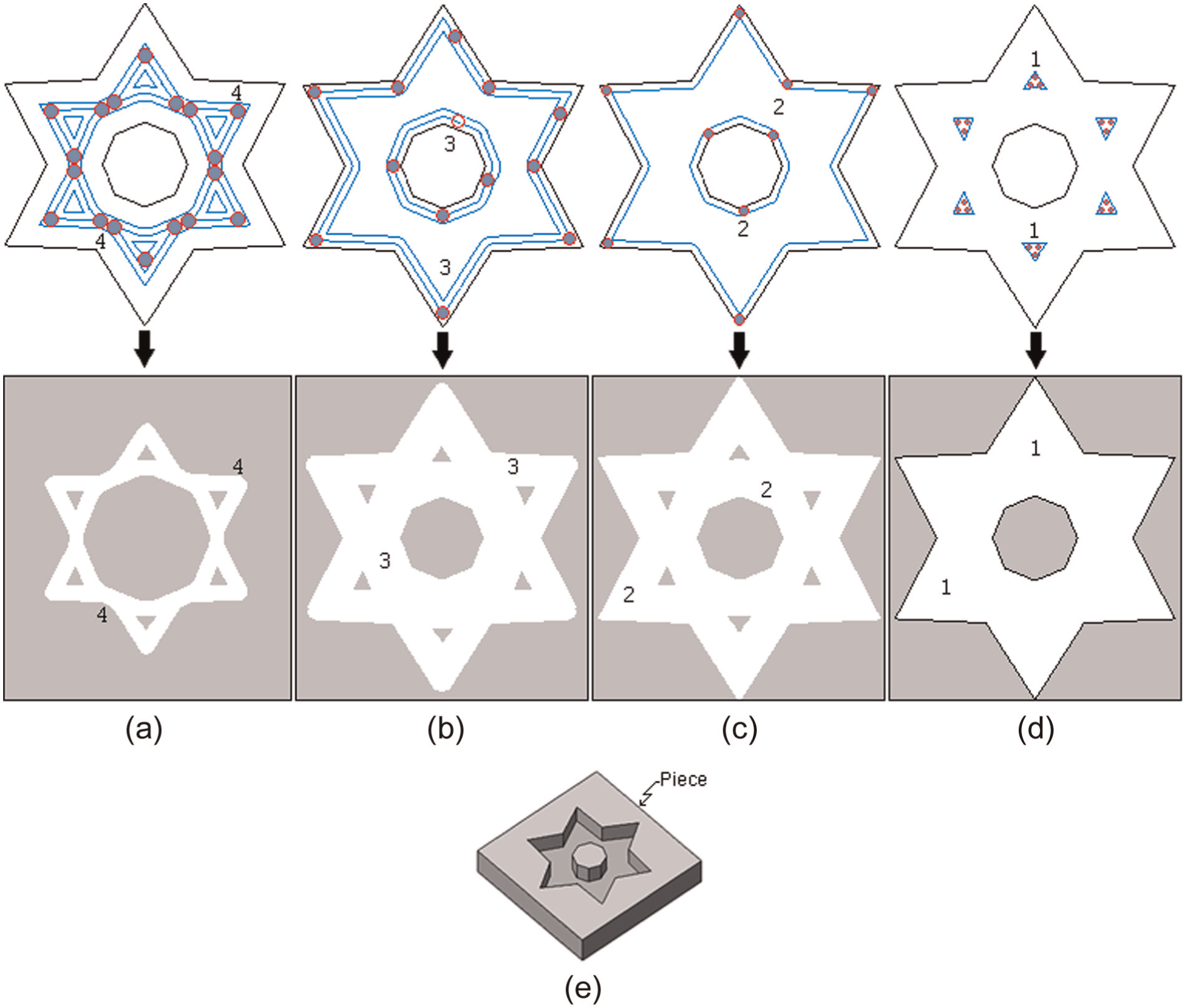
Tool selection for third piece (rough mill using zig with contour).
The developed software is shown in Figure 13. It was developed in Microsoft Visual C++ 2010 and tested with 2D and 2.5D images generated in any CAD software and exported to DXF file.
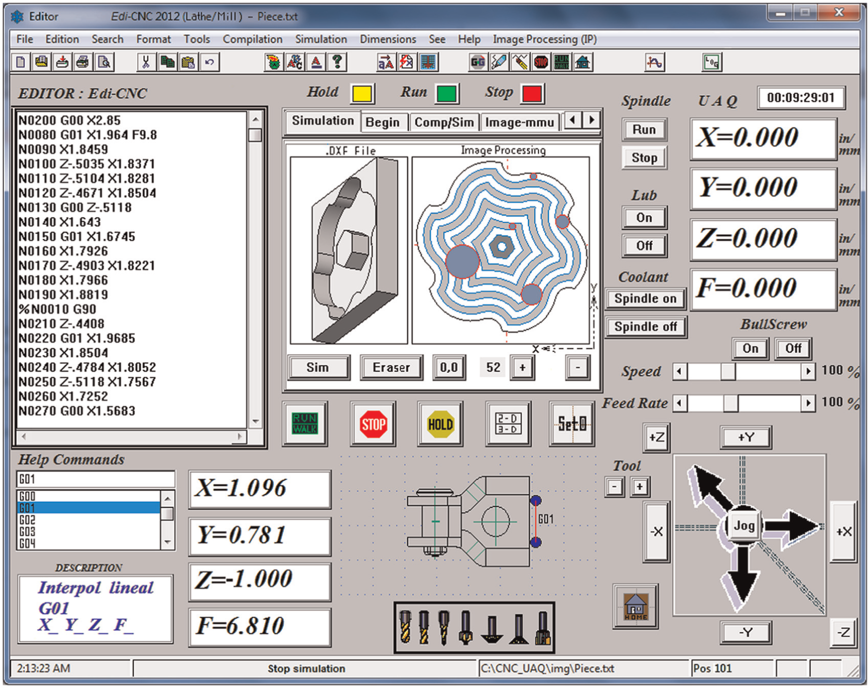
Final software for automatic tool selection.
Conclusion
In this article, a new method for automatic tool selection based on the shape, using special image processing techniques of directional morphological approaches for CNC milling machines, has been developed. The main contribution of this work is the new methodology for automatic tool selection, which consists of obtaining and converting a DXF file (in order to diminish errors) into a gray-scale BMP file, after the image is converted into a binary image, aiming at detecting and labeling the gradient and perimeter of the piece. Afterward, the tool size is taken from a database, selecting the more useful tool to machine the piece, utilizing an algorithm based on residues of pixel. Finally, mathematical morphologies for tool path generation strategy are carried out. The application of the proposed method implies advantages such as reduction of complex mathematical models, error reduction in cutting tool selection process, no necessity of a priori knowledge, speed and ease of use, and it also represents a practical way to simulate the process. Moreover, it can be suitable for other machining processes. In order to show the effectiveness of the proposed methodology, three pieces including common and important machining operations were evaluated. The calibrated system achieves a resolution of 1 µm, and according to the results, each piece can be processed in less than 1 s with an error of approximately 0.2%. In this sense, feasibility and reliability of the proposed method have been demonstrated. Furthermore, it can be applied in real processes, since it is based on standardized information (DXF file) available in most CAD/CAM commercial software.
Footnotes
Declaration of conflicting interests
The authors declare that there is no conflict of interest.
Funding
This article was financially supported by UAQ and financially by CONACYT (grant number 209333).