
Abstract
Tool selection is a very important step in manufacturing processes so as to improve productivity with high quality. The contribution of this work is the development of a new method for automatic tool selection in computer numerical control lathe machines, based on image processing techniques and information of the boundary of the piece, provided by either a .DXF file (drawing exchange format) or from an image taken with other devices. The proposed method detects the preferential direction in the boundary of the piece and creates a directional field through a directional gradient aiming at selecting the correct tool. Results from experiments show that the method makes it possible to work with a resolution of 1.1 micrometers, and to obtain good performance in automatic tool selection when several types of two-dimensional parts in the image are processed.
Introduction
Nowadays, a wide variety of complex geometrical shapes are made through a computer numerically controlled (CNC) lathe. There are numerous variables that affect the turning process, like material piece selection, cutting conditions, tool materials, tool sequence, cutting fluids and tool selection. A lot of investigation exists about the first topics; however, tool selection based on the shape has not been widely studied. At present, the commercial computer-aided manufacturing (CAM) software transfers this task to the worker who does it based on their own experience, ability and knowledge. Owing to the above an automatic technique that selects a tool based on the shape is particularly acceptable.
Some methods have been developed for automatic tool selection in turning or milling processes, such as that presented by Bouaziz and Zghal, 1 in which an optimization algorithm based on analytical models proposed a three-dimensional (3D) pockets machine obtaining good results only for prismatic pockets. Or that proposed by Ramaswami et al., 2 who used dynamic programming to determine the optimal set of tools, only to machine polygonal pockets. In the same way, You et al. 3 present a technique for arbitrarily shaped pockets. They used an upper bound procedure to choose the optimal tools for pocket milling.
In the case of tool selection and tool sequence problems in lathe machines, Oral and Cemal 4 presented a method that uses extensive rules base on feature information composed of years of heuristic knowledge. Edalew et al. 5 developed a hybrid approach based on mathematical and heuristic knowledge data modules to select the best set of cutting tools, optimal cutting parameters and machining time/cost, however, it needs a priori knowledge. Chung and Peng 6 use recognition characteristics of the piece shape contained in a .DXF format to select a proper operation and they use a dynamic SQL and investigation criteria to select the tool from the database.
On the other hand, image processing has been widely used in applications where studies from the cutting condition effects roughness in a single turning process according to Sarma et al.; 7 the prediction of cutting conditions in milling operations by Gadelmawla et al. 8 and path generation in milling CNC machines 9 are included.
The above mentioned research information presents certain disadvantages in tool selection, such as application of technology to specific parts, extensive rules for selection conditions, years of heuristic knowledge and use of criteria to select the tool; therefore, it is necessary to do research to satisfy all these aspects. The most remarkable advantage of the developed system is that the proposed method reduces the complex mathematical algorithms utilization and shows an easy way to simulate the cutting tool selection, in the same way, it eliminates the designer subjective decisions, reduces tool selection mistakes, makes the selection process and design faster and it is easy to use and does not require a priori knowledge.
This research presents a new technique based on image processing for automatic tool selection on a CNC lathe machine, in turning operations, such as external (longitudinal turning, transverse turning, grooving, chamfering, tapers, threading and profile turning) and internal (longitudinal turning, transverse turning, grooving, chamfering, tapers, threading and profile turning). The novel proposed method starts recognizing from a .DXF file. Then, a linear transformation is applied to a gray-scale image into a two-dimensional (2D) binary image. After the segmentation operation and the directional morphology is implemented to determine the position and direction absolute and relative reference frame for each edge of the pixel, the tool selection is achieved when a structural element, which has the shape of the cutting tool, is applied to each pixel located in the boundary. Also the zig and zig-zag trajectories are obtained with the same structural element and they are displayed in standard CNC code.
Background
Cutting tool
The automatic tool selection plays an important role to reduce machining time, errors, human interaction, costs and better product quality. Tool geometry selection is a complex task; however, the wide use of CNC machines in the industry justifies developing a methodology for this process. The development of cutting inserts of a diamond shape for a CNC lathe is varied (tool cutting edge angle greater than 90°). The development of 80°, 70° and 35° diamond-shaped cutting inserts, combined with various tool holders, made it possible to obtain a wide range of such tools. The most common external tools with 80° of diamond shapes are CNGG, CNGA, CNMA, CNMG, CNMP (ANSI standard nomenclature, insert form C = 80°, clearance angle N = 0°, tolerance G = ±0.05, insert type A); and diamond shaped internal inserts are SCLCR/L, SDUCR/L, SDQCR/L, SD-CR/L, SSSCR/L (holding method S = screw, shape C = 80°, lead angle L = 5°, clearance C = 7°, hand of bar r = regular/insert name L = left). The cutting tool is also named ID-Diameter-L/R for the internal tool and OD-Diameter-L/R for the external tool.10,11 In this research, data handbooks and catalogs of tool manufacturers were used to select the proper tool for turning operations.
Image processing techniques
Image acquisition
The common acquisition format of an object 3D image is; .DXF file, .IGES file, .STEP file, ParaSolid file, .CGM file, .STL file, CATIA file and HEAL GEOMETRY file. In this article the format .DXF is used owing to the ease and low cost in terms of computational work. Tufoi et al. 12 define the .DXF file format as information in an ASCII text file with .dxf extension. Chung and Peng 6 show the organization section of a .DXF file as: Begin of file, Header (this section contains general information about the drawing), Tables (contains definitions of named items), Blocks (describe the entities that make up each block in the drawing), Entities (this section contains the drawing entities), End of file.
Binary image
Between the methods more common to transforming a gray-scale image into a 2D binary image, are the thresholding, fixed thresholding, histogram-derived threshold, iso-data algorithm, background symmetry algorithm and triangular algorithm.
9
Thresholding is the most applied method to convert a gray-scale image
Edge detection
Edge is very important for image analysis and widely used for acquisition, registration, identification, segmentation and compression of object in the scene. 13 Some of the gradient operators used for edge extraction are: Sobel, Prewitt, Roberts, Canny, Zero-crossing and Beamlet transform. 14 The Sobel method is based on the first derivate and convolution of the image, called gradient operator, which includes a filter in the horizontal and vertical direction based over a mask. In this article the Sobel operator is used because of the low sensitivity to noise and low cost in terms of computational work.
Labeling of edge and components
To find connected components that form a region (edge) that represents an object in 2D binary images, there are several methods for labeling parts in images; recursive algorithm, sequential algorithm or that proposed by Sutheebanjard and Premchaiswadi 15 who used two new scan masks to connected labeled components. In this article, the method of sequential algorithm and scan mask are more commonly applied and used. The method consists of displacing a mask (of 4 × 4 pixels) through all pixels, saving the part edge trajectory.
Computer-aided design/manufacturing/engineering
Any computer software package that uses graphics and applications to facilitate engineering tasks in the design process can be categorized as computer-aided design (CAD) software. A system that plans, manages and controls the manufacturing operations through computer interface can be defined as CAM; and a system that analyzes the functions of a CAD drawing, allowing the user to simulate and study the way this will behave, can be classified as computer-aided engineering (CAE). The real development of CAD/CAM systems started in the 1950s and it was known as the era of the development of automatically programmed tools (APT) by General Motors. The 1960s was the period for interactive computer graphics. The 1970s was called the golden era for computer drafting and initial graphics exchange specification (.IGES) was initiated. In the 1980s and 1990s, new theories and algorithms evolved and integration of various elements of design and manufacturing were developed (CAE). Today the major research and development focus was to expand CAD/CAM/CAE systems beyond three-dimensional geometric designs and provide more engineering applications.11,12,16
An example of application of image processing in manufacture is the work published by Chen et al., 17 where an image-based method for examining the profile accuracy of grinding wheels is used for micro-drill fluting. For measuring the height of the end-milling burr on the edge of a workpiece using techniques of image processing is another example that provides a new strategy to this methodology. 18
Methodology
The use of image processing to solve manufacturing problems is a new technique in literature. In this article, eight steps to get the selection tool using image processing are proposed. In this way; the original design is taken from a CAD (wire-frame model) as a .DXF file. Then a method of data extraction 6 is applied to generate the image to find the equivalence between pixels and millimeters. After, different transformations using image processing, such as labeling to define the part of the image, the gradient to find the slope and edge to detect the position of the gradient vector is applied.
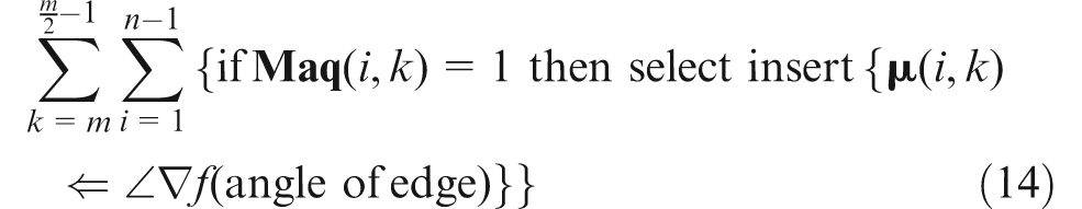
A structural element with the shape of the cutting tool, with angle
Figure 1 shows two conditions, if the angle of the cutting tool (
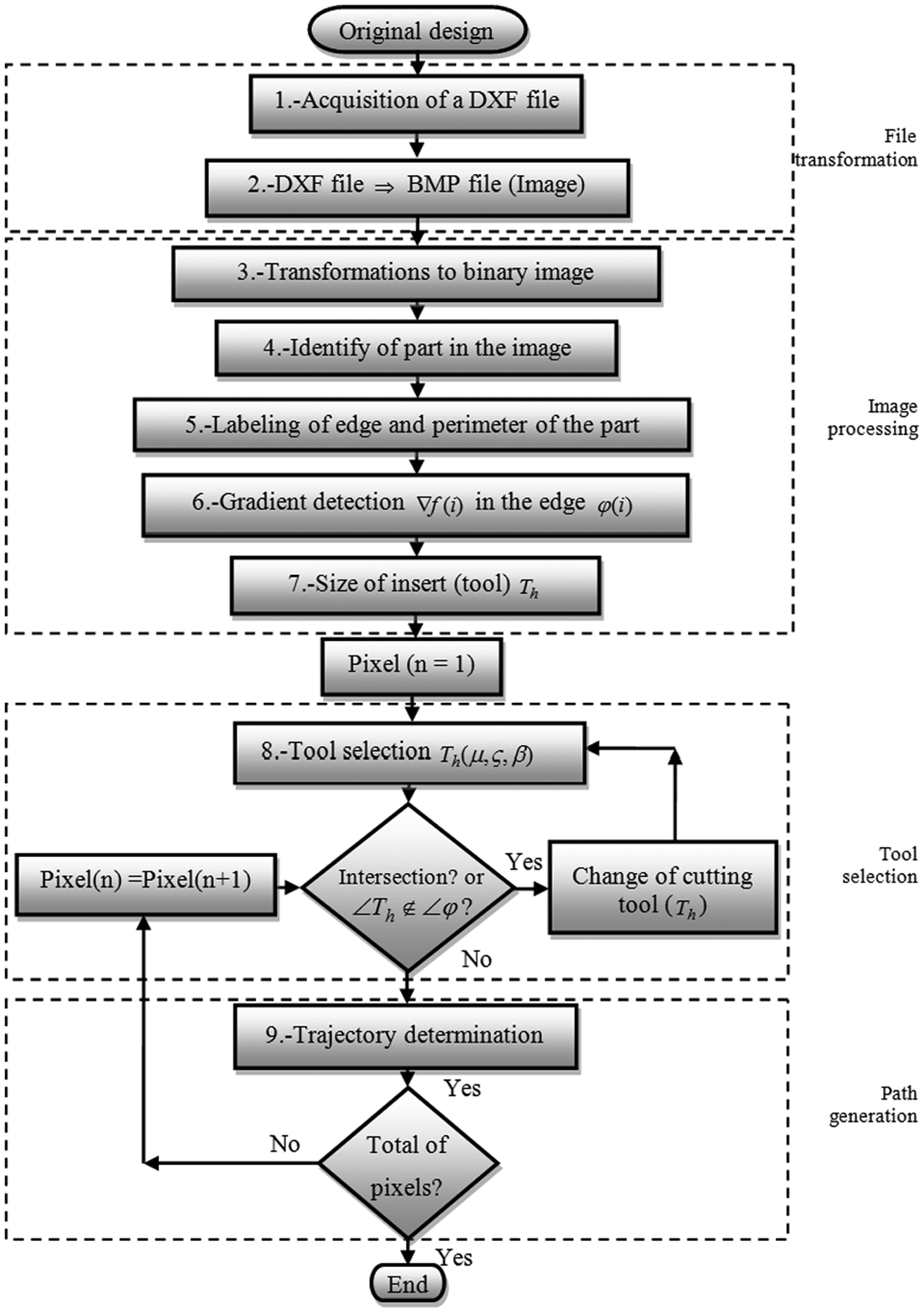
General diagram of the automatic cutting tool selection.
Step 1. Acquisition of .DXF file
The original design (Figure 2(a)) is obtained from CAD, then the upper profile model is converted to a DXF file. 19 This file contains general information about the drawing, definitions of items, and the entities that make up each block are shown in Figure 2(b).
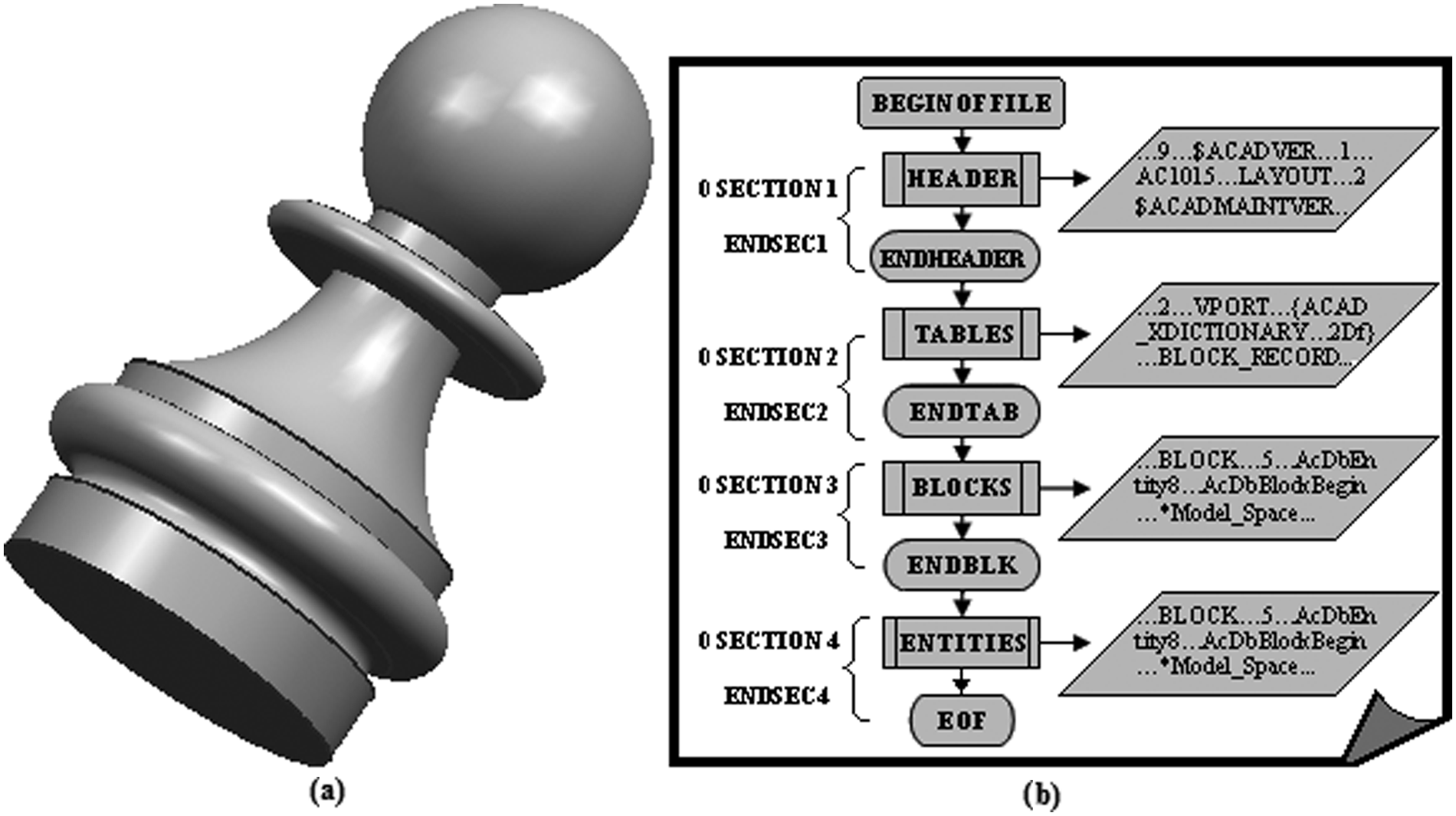
Originals file: (a) design from CAD; (b) .DXF file.
Step 2. File transformation
A precision analysis, before and after applying image processing techniques, to find the most appropriate resolution according to the dimensions of the parts to be machined (maximum test pattern used 50.800 mm) and cutting tools (pattern maximum test used 19.049 mm), are shown in the Table 1. The calibration value is also the resolution of this system and it is approximately 1.1 μm.
The resolution of this system.
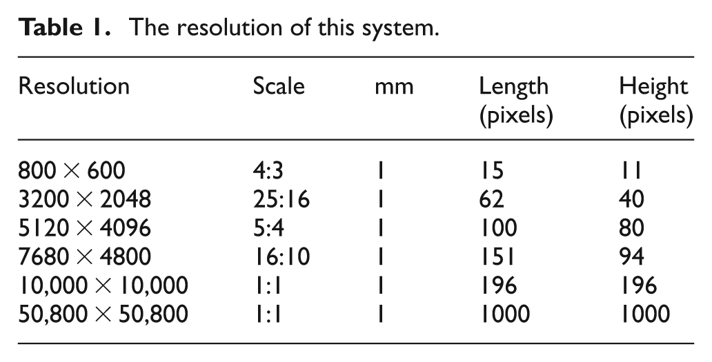
A method of data extraction6,19 is applied to convert .DXF file to a .BMP file, obtaining Figure 3(a) and (b). The same distance is then automatically determined in pixels in the image and a calibration value is obtained by dividing the distance in millimeters by the distance in pixels to obtain a relation of millimeters per pixel

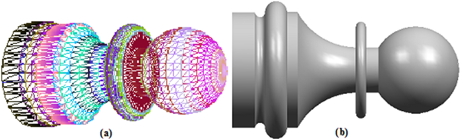
Files: (a) design without texture (wire file); (b) image (.BMP file).
All the dimensions are known in the .DXF file. In order to find the directional gradient of the edge, image processing is applied.
Step 3. Transformations to binary image
The space of a characteristic of an image (

and also
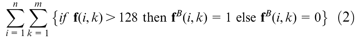
where
Step 4. Part identification
The following step is the binary label, or limitation, of the part
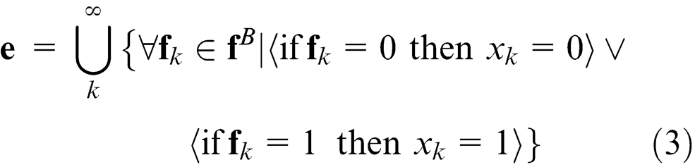
or also written as
where
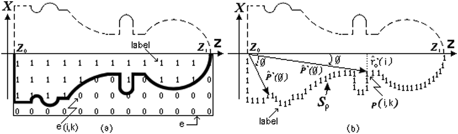
Labeling definition: (a) labeling of the part; (b) labeling of the perimeter.
Step 5. Labeling edge and perimeter
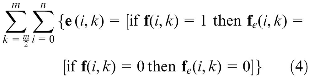
The perimeter (
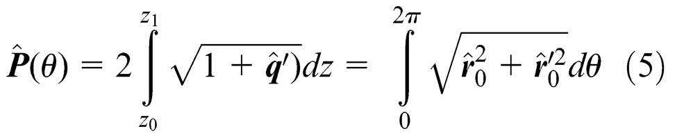
where the vector
The integral is defined as a sum of the function
where the
Step 6. Directional morphology and gradient vector in the edge
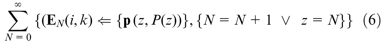
The edge of the digital image is obtained by the evaluation of significant discontinuities in pixel intensity,
17
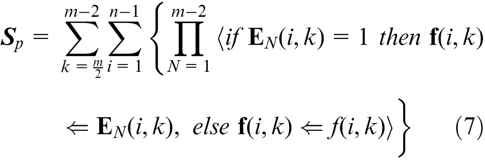
the gradient, give position, orientation and direction of the part (machining workspace). A transformation (
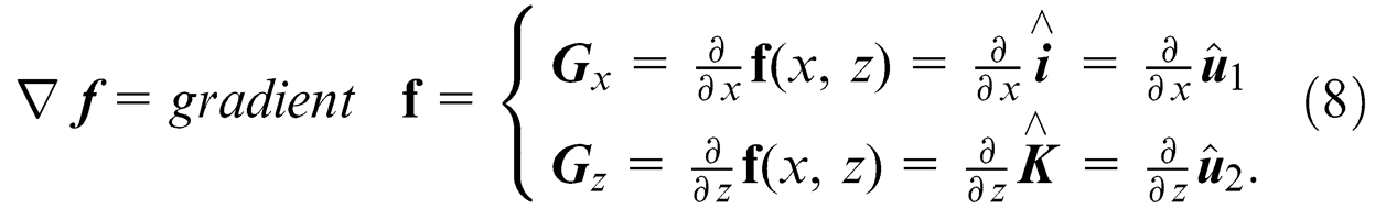
therefore
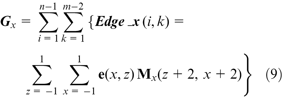
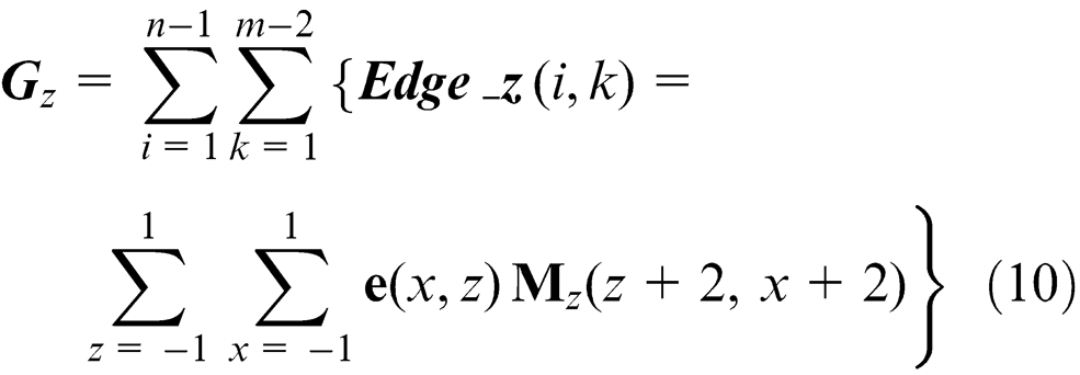
Here
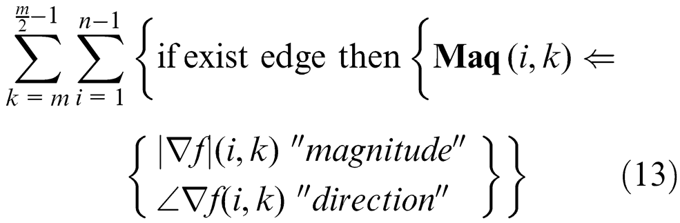
The magnitude (


Figure 5(a) illustrates the vector direction of the edge of the part sample. Figure 5(b) shows the directional angles according to the trajectory of the edge when the gradient is applied to the binary image in the part.
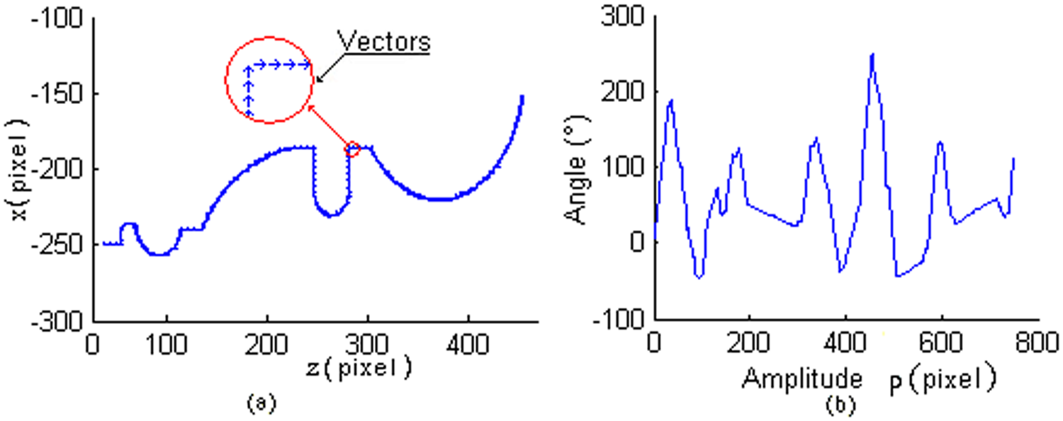
Vectors of part: (a) direction vector of the part; (b) magnitude of edge direction.
The magnitude and direction of the edge is saved in the variable
Step 7. Tool selection
During the cutting operation, it is necessary to consider possible crashes with different machine tool elements, such as: the spindle, tool holders in the turret and tailstock, among others. These elements limit the workspace and should be taken into account. However, in this investigation only the workpiece, the insert, and tool holder are studied, since the whole workspace requires a deep study for its determination and depends on each machine structure, also it will require more time processing and screen resolution. The direction of the edge allows selecting the type, size and the angle of the insert, which is represented by the structural element in the image processing part. Table 2 illustrates the common types of cutting tools used in turning operations: left (L), right (R), neuter (N), knife (K), drilling (D) and holder (H) for external machining and their equivalents for internal works, where
Common inserts (structural element).
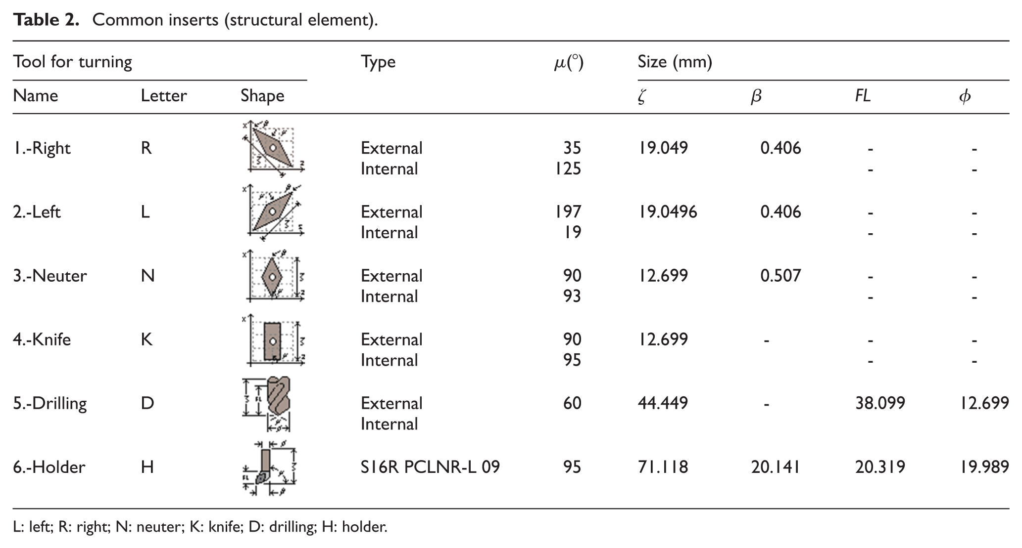
L: left; R: right; N: neuter; K: knife; D: drilling; H: holder.
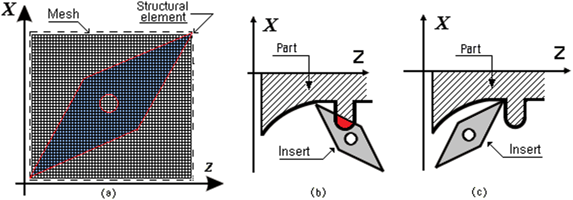
(a) Structural element for the right insert; (b) incorrect insert; (c) correct insert.
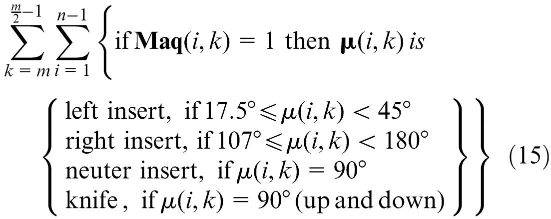
To identify the most suitable insert, the directional vectors of the edge (
If
If
When the structural element moved through the image and the edge has a value (
where
After an insert is selected, following the order of Table 2, the structural element shown in Figure 6(a) is moved through the edge in a way, such that the cornering structural element, which represents the nose cutting, coincides with each pixel of the edge. If at any pixel of the edge there is an intersection between the part and structural element (Figure 6(b)) the insert is not correct and another insert is tried (Figure 6(c)) by repeating the same process. The procedure of intersection of the insert with the part is checked using image processing techniques with software (it was developed in Microsoft Visual C++ 2010). All pixels contained in the part are labeled in coordinates (
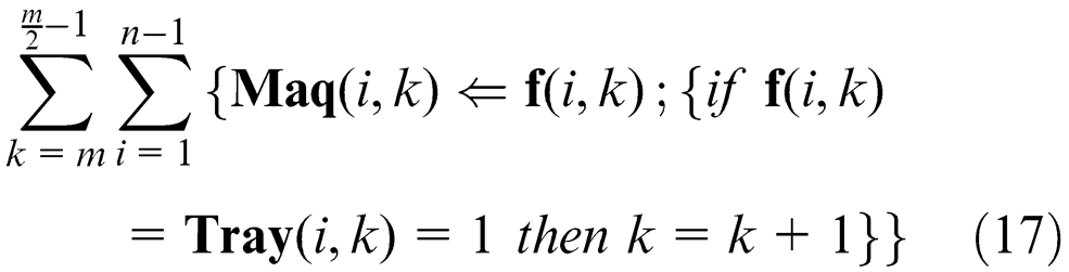
After the correct holders 22 and inserts have been selected to work on each area, many changes of cutting tools will probably be required. The number of changes can be reduced by ordering the changes with the next procedure
where
Step 8. Tool path generation strategy
The methods of trajectories generation are: zig (one way), zig–zag (two ways), zig with contour, zig–zag with contour, follow-periphery, trochoidal and profile.
23
In this article the zig and zig with contour are used because of the easy generation of trajectories. Here it is important to clarify that path generation is only for rough cutting. The first machining is presented in Figure 7(a), the strategy is linear zig. The tool path is obtained by an algorithm (zig). Each pixel of the edge is labeled with a position-relative reference frame (
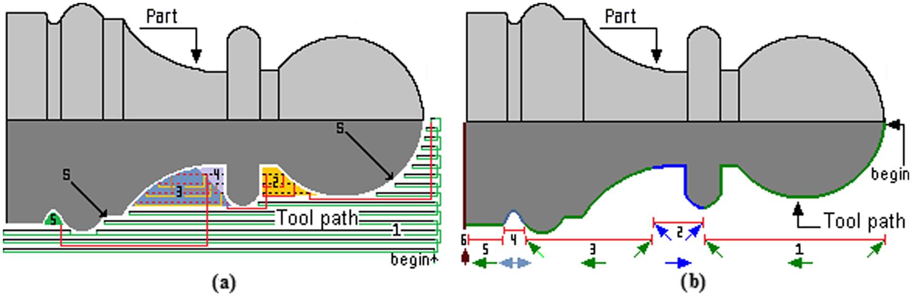
Tool selection (final piece): (a) rough turn (zig); (b) finish turn (zig with contour).
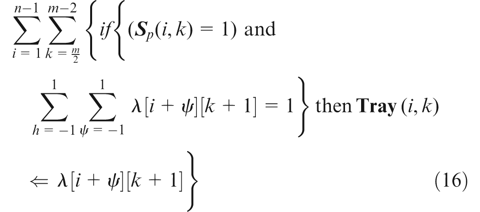
On any image if a fix
Equation (18) can be used to determine the time of machining

Results and discussion
Aiming at improving accuracy, the dimensions obtained from image processing are compared with the dimensions obtained from the .DXF file.
With the proposed method, an image can be directly taken with a photograph camera or other device for automatic tool selection. The methodology presented above is applied to the manufacture of two parts that includes operations of external rough cutting, internal rough cutting and the approach of the thread. Nine tools are available for machining one 2D part, four for external roughing (left, right, neutral and knife), four for internal roughing (left, right, neutral and knife) and one for threading. The parameters of each cutting tool are presented in Table 3.
Selected inserts for part of Figure 7.
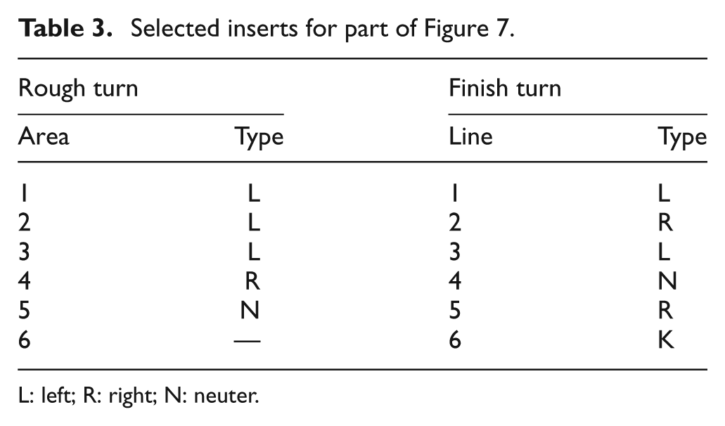
L: left; R: right; N: neuter.
The first example is the manufacture of a chess piece as presented in Figure 7. The selection of the cutting tools is presented in Table 3 and the cutting path for rough cutting is shown in Figure 7(a) and (b). The label
Table 3 shows the results of the selected inserts by applying the proposed method.
The second example is presented in Figure 8. The selected cutting tools are presented in Table 4. Where the existing thread machine is represented by 4 and an internal machining labeled with the number 5.
Cutting tool selection for second example.
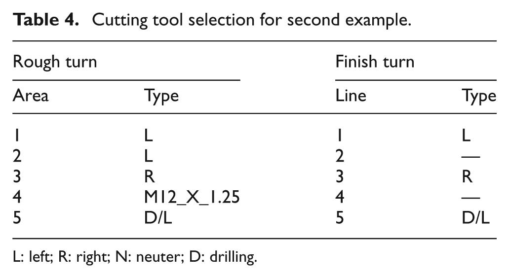
L: left; R: right; N: neuter; D: drilling.
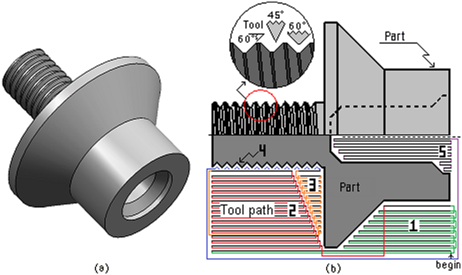
Tool selecting: (a) final piece, (b) thread and rough turn (zig)
The developed software is shown in Figure 9. It was developed in Microsoft Visual C++ 2010 and tested with 2D images generated in any CAD software and exported to .DXF file.
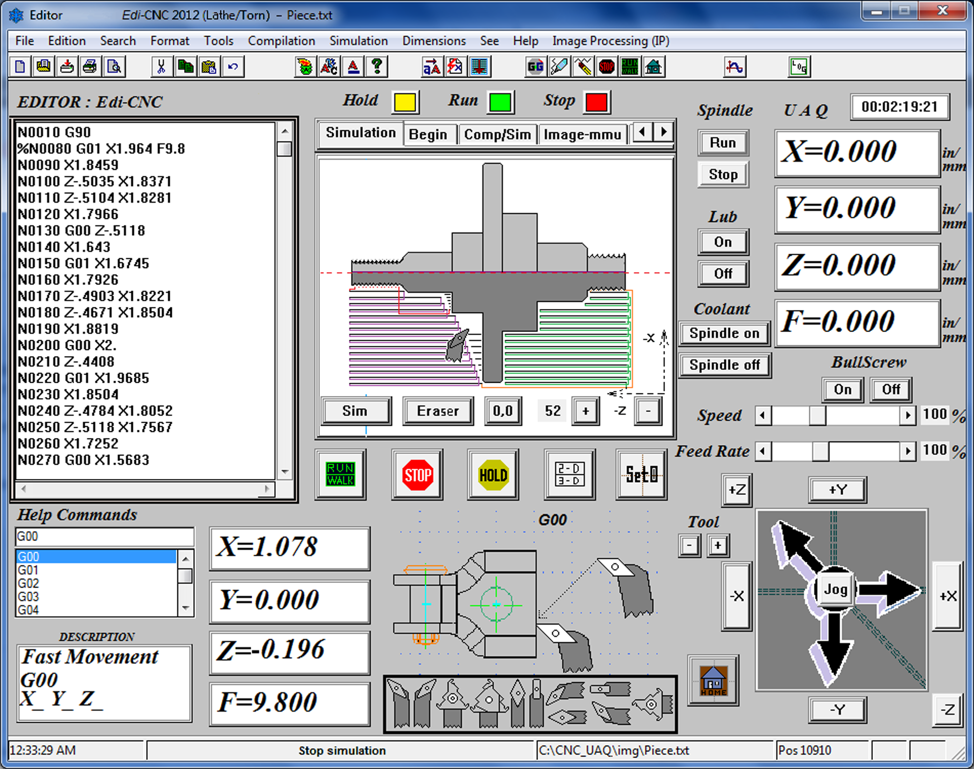
Final software for tool selection.
Conclusions
The present work develops a new method for automatic tool selection using image processing techniques for computer numerical controlled lathe machines. The main contribution of this work is the use of image processing to generate a new method for automatic tool selection where the preferential direction field is detected in the boundary of the image part and creates a directional field through the directional gradient. In order to diminish the possible error in boundary obtaining, a .DXF file was used to compare and correct it when an image is utilized. Experimentation shows that the proposed method works with a resolution of 1.1 micrometers and it has good performance owing to the automatic tool selection, which can be carried out correctly. The application of the proposed method, developed in this investigation, reduces the complex mathematical algorithm utilization, shows an easy way to simulate the cutting tool selection and it can be suitable for other machining processes for further investigations. The resolution of this system is determined as approximately 1.1
Footnotes
Acknowledgements
This article received financial support from UAQ and financial support by CONACYT (grant number 209333).