
Abstract
The increasing demand for green products and strategies has led to research on reducing manufacturing costs and energy consumptions. In this study, the brazing method was applied to the fabrication of a micro-end-mill for printed circuit board manufacturing, and the machining properties of the fabricated tools were experimentally investigated. A tungsten carbide cutting edge was brazed onto a stainless steel shank using silver filler, and this material rod was fabricated into a micro-end-mill with a diameter of 800 µm. Machining results for this micro-end-mill were observed via scanning electron microscopy, and an abnormal wave pattern was observed on the cutting surface when using the brazed tool. The woven structure of the workpiece is thought to be the cause of this phenomenon; the wave pattern can be removed by controlling the machining conditions. Since the brazing technique is readily applicable to micro-scale cutting tools, it is expected that these results will contribute to improved machining quality when using brazed micro-cutting tools, as well as improved manufacturing efficiency.
Introduction
Printed circuit boards (PCBs) are high-priority components in almost every electronic product. Since the electronic circuit path is printed on nonconductive sheet material, PCBs facilitate miniaturization of electronic devices with high levels of integration. PCBs contain a number of holes and slots connecting the circuit path, and micro-end-mills with diameters of several hundred micrometers are used to machine the slots. In accordance with recent remarkable developments in the PCB industry, several approaches have been studied to improve machinability and productivity.1–3
Nowadays, green products and strategies in manufacturing have become more important, mainly due to increasing environmental concerns. From the point of view of energy consumption, Kong et al. 4 evaluated the machining tool path in terms of environmental factors. Yoon et al. 5 measured energy consumption during PCB drilling and calculated other aspects related to manufacturing cost under various machining conditions.
However, research on the material development of micro-end-mills has been largely motivated by the high price of tungsten carbide (WC). Since tool material occupies a significant proportion of production cost, tool manufacturers need to develop alternative materials for effective cost reduction. In particular, owing to recent advances in manufacturing technology, the brazing technique, which was originally used for conventional end-mills, has been investigated in this context. In this technique, a cutting edge made of high-hardness material, such as WC, is attached to a reusable shank made of low-cost material. Several technologies have been developed such as laser micro-welding or e-beam exposure;6,7 however, there is virtually no published research on end-mill brazing, especially at micro-scales, aside from some results on machining performance in terms of the brazing temperature profile.
In macro-scales, heat flow through a brazed lathe-cutting tool was investigated via finite element (FE) simulation, 8 and tool wear characteristics of a brazed tool were examined. 9 For turning, electron beam–activated brazing technique was introduced for brazing cubic boron nitride (CBN) onto a WC insert. 10 Recently, the brazing technique has been used to attach diamond to the flank surface of a drill, in order to machine difficult-to-cut material such as carbon fiber–reinforced plastic (CFRP) more efficiently. 11 However, in micro-scale particularly, the machining performance is more difficult to control than that of conventional-scale drilling since the tolerance dimensions are larger compared to the dimensions of the bit itself. 12 Thus, an experimental investigation is required to evaluate the machining properties of brazed end-mills.
It is intuitively clear and well known to tool manufacturers that the machining performance of a brazed micro-end-mill cannot be better than that of a solid material end-mill. In this study, the machinability of a WC/stainless steel (SS) brazed end-mill was compared to that of a solid end-mill, with an emphasis on cutting surface quality. Wave patterns, similar to surface waviness defects reported on woodworking in 2002, 13 were observed on the cutting surface when the brazed end-mill was used, and the causes were analyzed. In addition, the structure of the Copper Clad Laminate (CCL) workpiece material was examined. This article reports the machining properties of a brazed micro-end-mill for the first time and suggests an appropriate configuration of machining conditions to reduce defects in PCB routing.
Manufacture of the brazed end-mill
In order to assess the manufacturing characteristics of the brazing technique, WC solid and WC/SS brazed micro-end-mills were fabricated, each with a diameter of 800 µm (WET800; Neo Technical System Co., Ltd, Korea). For the solid end-mill, a cylindrical carbide rod was fabricated using several grinding process steps following the conventional fabrication methods. However, for the brazed end-mill, a WC rod and a SS rod were joined first using a filler and then ground into a cylindrical rod shape. Then, the fabricated rod was ground into end-mill tool using conventional fabrication methods. After the brazing process, since WC solid and WC/SS brazed micro-end-mills were fabricated using the same grinding process, the geometry of cutting edges are same. Geometry of micro-end-mills was checked again using optical microscope, in order to confirm shape of cutting edges.
Figure 1 shows the geometrical features of two types of fabricated end-mills in detail. The border between the WC and SS is indicated by different colors. Silver solder, which is a common brazing material, was used as the filler for joining. During the brazing process, the silver filler was inserted between the two kinds of material rods, with a thickness of about 200 µm, and the composite rod was squeezed together under high temperature and pressure.
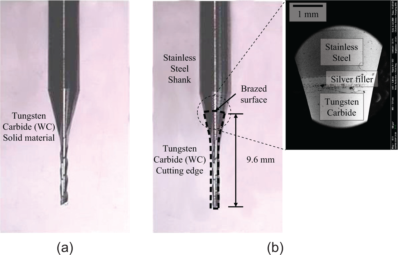
(a) Fabricated WC solid and (b) WC/SS brazed end-mills. Total tool length is 38.1 mm.
Experiments
Cutting surface of a machined slot
The end-milling system was constructed to compare the machinability of two different types of end-mill. The system consisted of a three-axis stage (404XR150; Parker Corp., USA) and a spindle (HEN-40; Fischer, Switzerland). The workpiece material was 15 stacks of CCL (DS-7409 0.15t; Doosan Co., Korea), a raw material for PCBs. The workpiece was fixed on the jig in the xy-plane and machined in the y-direction. The end-mill tip was positioned to extrude 1 mm from the bottom of the last stack. Height of contact area between tool and workpiece was 2.25 mm.
To analyze the effect of the machining conditions on the machining quality, various end-milling experiments were performed. Since the variables were the feed rate and rotational speed of the spindle, the milling experiments were planned with those two parameters. WC solid and WC/SS brazed micro-end-mill was compared with same reference condition first and then WC/SS brazed tool was tested with various process parameters. Table 1 shows experimental machining condition.
Experimental machining condition.
WC/SS: tungsten carbide/stainless steel.
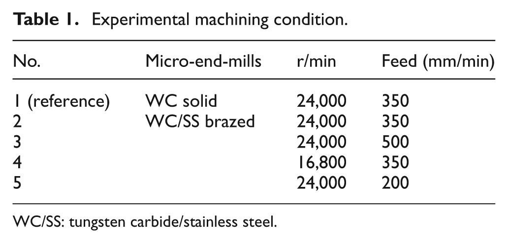
The machining results, cutting surface after machining, observed via scanning electron microscopy (SEM; ISI-SX-40; International Scientific Instruments, Murrieta, CA, USA), are shown in Figure 2. The wave pattern was quantified in terms of the wavelength and height of the pattern. As shown in Figure 2(a), the end-mill proceeded in the right-hand direction and rotated in the clockwise direction. A wave pattern appeared for the WC/SS brazed end-mill (Figure 2(b)); this did not occur for the conventional WC tool. The pattern appeared only on the right, or down-milling, side of the machining.
(a)–(c) Cutting surface results observed via SEM at various machining conditions and (d)–(e) the measured specifications of wave pattern when using brazed tools: (a) WC solid tool, 350 mm/min, 24,000 r/min; (b) WC/SS brazed tool, 350 mm/min, 24,000 r/min; (c) WC/SS brazed tool, 200 mm/min, 24,000 r/min; (d) height; and (e) wavelength.
As Figure 2(b) indicates, the wavelength is the distance between the highest points of consecutive waves, and the height of the wave is defined as the average height difference between the highest and lowest points of the same wave. Pattern wavelengths and heights were measured for the different machining conditions. Centering on the reference condition, two other conditions have same chip load values. Chip load is defined as the thickness of removed chip in each rotation, or material removal load acting on the cutting tool, and could be calculated by dividing the feed by the spindle speed. A higher chip load created a bigger wave on the machining surface, and the height of the wave was more sensitive to the feed rather than the spindle speed. There was little variation in the wavelength, but it was little bit longer at the lower rotational speed because cutting edge removes workpiece with slow rate. Considering that tool moves with the speed of feed, frequency of wave pattern could be calculated by dividing the feed with the wavelength of pattern. However, calculated value of frequency is nearly 20 Hz and is not related to the rotational speed of the spindle.
Interestingly, wave pattern could be removed at a certain low feed rate. As shown in Figure 2(c), the cutting surface was as smooth as in the solid tool machining case.
Structural analysis of the workpiece
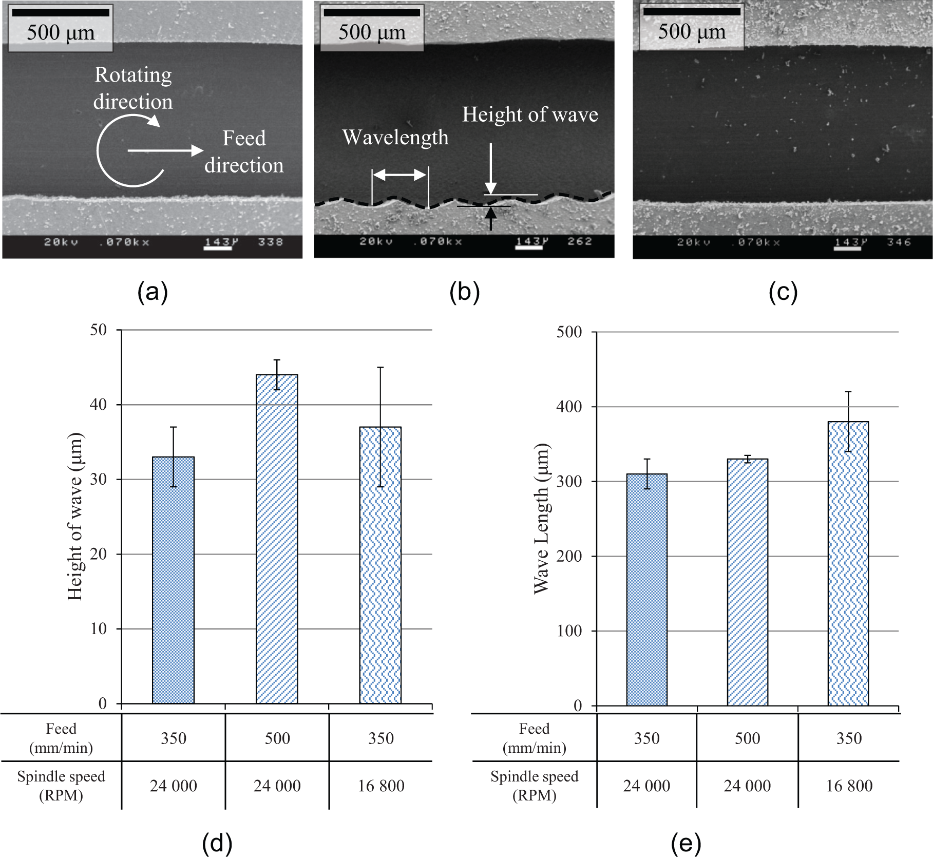
According to the results discussed in section “Cutting surface of a machined slot,” a wave pattern occurred when machining with a brazed end-mill. To analyze the causes, the CCL workpiece was examined. CCL is made by weaving a glass fiber bundle horizontally and vertically. Figure 3 shows a schematic and cross-sectional image of the workpiece. Depending on the position of the glass fibers, the applied stress is expected to be different, and thus, the wave pattern appeared according to the machining conditions. From the cross-sectional image of the workpiece, the wavelength was obtained as about 390 µm, which is similar to the values appeared in Figure 2(e).
Cross-sectional image of the workpiece material, CCL: (a) SEM image and (b) schematic.
A bending test was also conducted to investigate the resistance force of the tool. Figure 4 shows a schematic diagram of the bending test and the measured results. The end-mills were fixed same as the machining states, and force was slowly applied perpendicular to the axial direction of the tool. The inclination of the force was calculated in terms of the deformed distance, only from linear elastic deformation region. Tool breakage occurred before 1 mm of deformation, and the force/deformation inclination of the solid tool was much higher than that of the brazed tool, as like as general intuition. Stiffness of the tool is very important to obtain a good machining quality. This result could help explain why the abnormal wave pattern defect appeared only while PCB machining with the brazed tool.
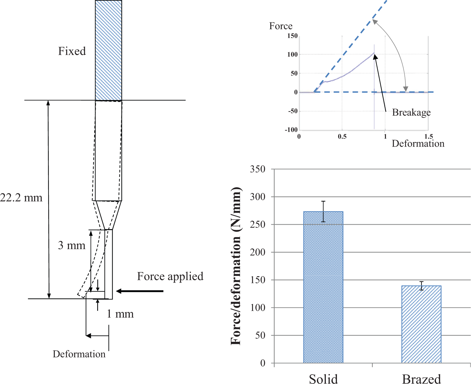
Schematic diagram of the bending test and the measured force in terms of deformation when a bending force was applied.
Conclusion
In this study, the machining properties of a WC solid end-mill and a WC/SS brazed end-mill were observed and compared. When machining with the brazed end-mill, a wave pattern appeared on the cutting surface. It is thought that the wave pattern was caused by the woven structure of CCL. A woven structure has different mechanical properties according to the position of the fiber bundle, and thus, it creates a wave pattern on the cutting surface. The wave height and wavelength of the pattern were slightly affected by the machining parameters, and the feed rate was more sensitive than the rotational speed in regard to the occurrence of the wave pattern.
Accordingly, the chip load was largely lowered (by lowering the feed rate) in order to remove the wave pattern on the cutting surface and improve the machining quality. The resulting cutting surface was as smooth as those machined with the WC solid end-mill. Since this is the first reported occurrence of a wave pattern defect on a cutting surface end-milled with a brazed micro-tool for PCBs, it is hoped that this article will contribute to the technical development of brazed micro-tools and cutting strategies for machining woven composite structures.
Footnotes
Declaration of conflicting interests
The authors declare that there is no conflict of interest.
Funding
This work was supported by Neo Technical System, the Brain Korea 21 project at Seoul National University, the Korea Institute for Advanced of Technology (KIAT) project funded by the Ministry of Economy Knowledgement (no. 2010-TD-700203-001, 100110-2), and the National Research Foundation of Korea (NRF) grant funded by the Ministry of Education, Science and Technology (MEST) Korea (no. 2012-0008727).