
Abstract
Digital manufacturing techniques can simulate complex assembly sequences using computer-aided design–based, ‘as-designed’ part forms, and their utility has been proven across several manufacturing sectors including the ship building, automotive and aerospace industries. However, the reality of working with actual parts and composite components, in particular, is that geometric variability arising from part forming or processing conditions can cause problems during assembly as the ‘as-manufactured’ form differs from the geometry used for any simulated build validation. In this work, a simulation strategy is presented for the study of the process-induced deformation behaviour of a 90°, V-shaped angle. Test samples were thermoformed using pre-consolidated carbon fibre–reinforced polyphenylene sulphide, and the processing conditions were re-created in a virtual environment using the finite element method to determine finished component angles. A procedure was then developed for transferring predicted part forms from the finite element outputs to a digital manufacturing platform for the purpose of virtual assembly validation using more realistic part geometry. Ultimately, the outcomes from this work can be used to inform process condition choices, material configuration and tool design, so that the dimensional gap between ‘as-designed’ and ‘as-manufactured’ part forms can be reduced in the virtual environment.
Introduction
It is anticipated that composite materials will play a key role in the development of next-generation transport platforms through the remainder of the 21st century. 1 Composites in general and carbon fibre–reinforced plastics (CFRP), in particular, possess attractive properties such as improved structural performance and lower product weight when compared with their traditional metallic equivalents. As well as innovation in the delivery of key in-service performance requirements, the material systems used on modern vehicles must also offer more sustainable solutions for life cycle management, 2 including how they impact the environment through design to manufacture, to safe use in service and, ultimately, to disposal or recycling.
Although composites have been in use for transport applications in a number of combined material formats for several decades, the disposal of thermosetting matrix systems, in particular, at end of life remains a significant challenge. Thermoplastic matrices currently offer superior recyclability and are becoming more effective in terms of structural performance, 3 environmental impact and, importantly, cost. 4 When compared with typical thermosetting CFRP manufacturing methods, energy consumption reductions of up to 90% are achievable using thermoplastic forming processes, where processing times are of the order of minutes rather than hours. 5 Thermoplastics such as Fortron® polyphenylene sulphide (PPS) can be recycled many times with minimal degradation or loss of physical properties. 6 Thermoform ability and weldability of thermoplastics already differentiate them from thermosets 7 from a manufacturing perspective, and they can also offer superior toughness and durability. Other significant attributes include higher heat resistance and greater impact strength relative to current thermosetting systems. For example, service temperatures of 350 °F (compared with 200 °F) and toughness levels of the order of 2–3 times that of composites made from epoxies are possible. Non-autoclave methods for the manufacture of advanced thermoplastic composites can facilitate the application of light weight, durable product structures with significant cost advantages compared with autoclave-based thermoset manufacturing. 8
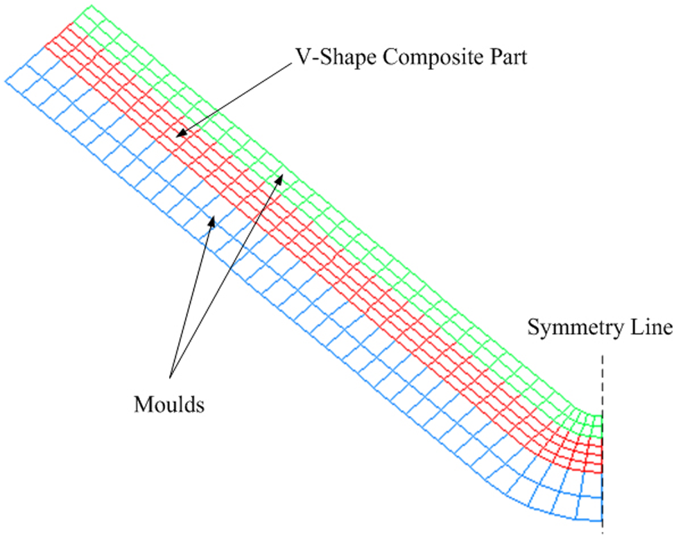
Despite the stated benefits and increasing application areas, CFRP parts (both thermosetting and thermoplastic) can be prone to undesired deformations during and after combined temperature and pressure processing conditions. The process-induced deformation of carbon fibre–reinforced thermoplastic (CFRTP) parts during thermoforming is a significant factor when designing mould tools, configuring the material layout, specifying processing parameters and specifying tolerance levels for manufacture and assembly. These deformations also reduce the value of any digital mock up 9 used for virtual build validation as the dimensions of the nominally sized virtual parts differ from those on parts manufactured using real forming processes. Depending on the part geometry, the constitutive behaviour of the material and the forming process employed, changing primarily two-dimensional (2D) sheets of raw material into three-dimensional (3D) curved and/or angled geometry may lead to undesirable part deformations, which do not match the as-designed form. The most common effect of residual stresses in composite products is the deformation of angled and curved parts. 10 With a typical positional tolerance specified at ±0.2 mm 11 for an aerospace application, it is important that the behaviour of angular features is understood, so that angular dimensions can be controlled to the extent that this tolerance can be achieved. Process-induced deformations mainly affect the dimensional control of finished components, and this can lead to increased costs as parts become more difficult and therefore more time consuming to fit in place during assembly, as shown in Figure 1. Bottom lines can be affected as manufacturers require concessions leading to price reductions or in critical cases; manufacturers have to absorb costs as non-compliant parts are scrapped. 12
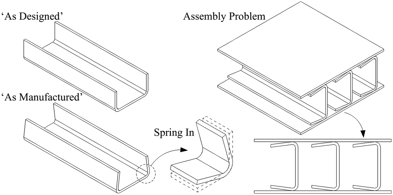
Problems in generic panel assembly due to composite deformation.
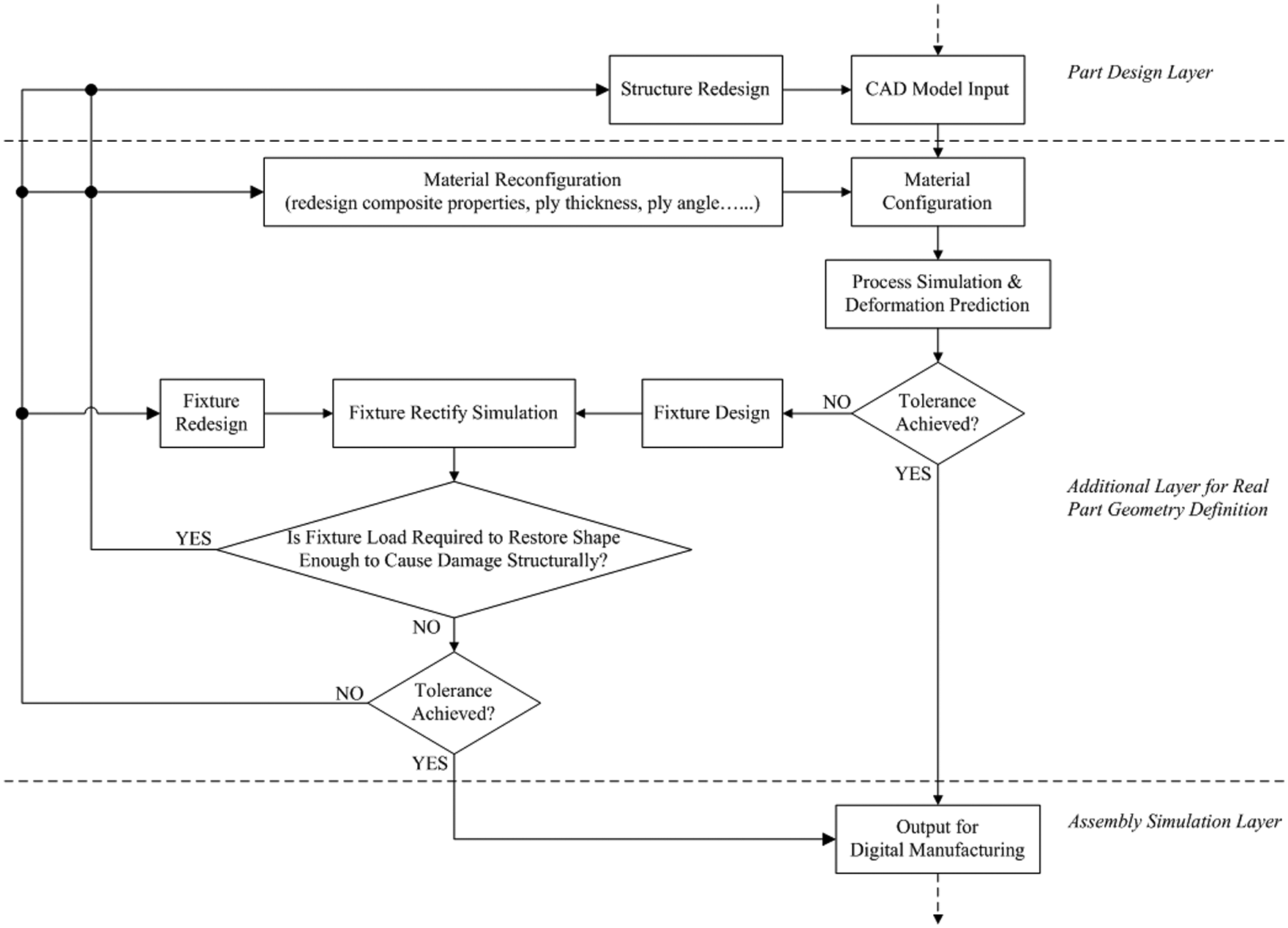
The prediction of the final part angle using the methods presented here would enable the designer to tailor the material system or processing conditions to control the angle to within the required tolerance. The primary objective of this work is to cover the current gap between conventional part design methods and final assembly simulation platforms for CFRTP components by simulating the manufacture of a 90° angled component using the process of thermoforming. The choice of a thermoplastic-based material system for this work is based on its more favourable characteristics when considering its sustainability relative to the more commonly used thermosets. In order to broaden the structural applications for CFRTPs, their behaviour during manufacture must be characterised, so that designers and manufacturing planners can fully understand and predict how they will perform as they are formed and assembled. The method presented here will predict simulated ‘as-manufactured’ part geometries for a simple 90°, V-shaped angle and the approach used to transfer this data to the 3D computer-aided design (CAD) environment for the purpose of completing an assembly simulation. This work represents the first step in a process intended to create an additional layer of simulation methods, which needs to be defined, validated and integrated within a digital manufacturing framework to synthesise accurate composite part form prediction methods with the build validation tools already developed in the digital manufacturing environment, as shown in Figure 2. With these prediction and simulation technologies, digital manufacturing platforms will help engineers and process planners to plan and deliver fully optimised manufacturing data for composite structures to the production environment quickly and efficiently. Composite part forming and product assembly simulation can therefore be included in the design process from the earliest conceptual stage, ensuring high levels of part and product accuracy through to production.
Proposed methodology for composite component shape prediction.
Method
Thermoforming equipment
One of the major attractions to thermoplastic-based composite systems is the potential rapid processing rates 13 that they offer compared with existing thermoset systems that require much longer and expensive autoclave processing. Thermoforming14,15 is a family of processes that can be used to process thermoplastic-based composite materials by the combined action of heat and pressure. In its simplest form, thermoforming is a three-stage process, involving heating of the raw material blank, coupled with thermal de-consolidation, followed by part forming and re-consolidation in a matched tool, with the final process step part ejection from the tool, as shown in Figure 3.
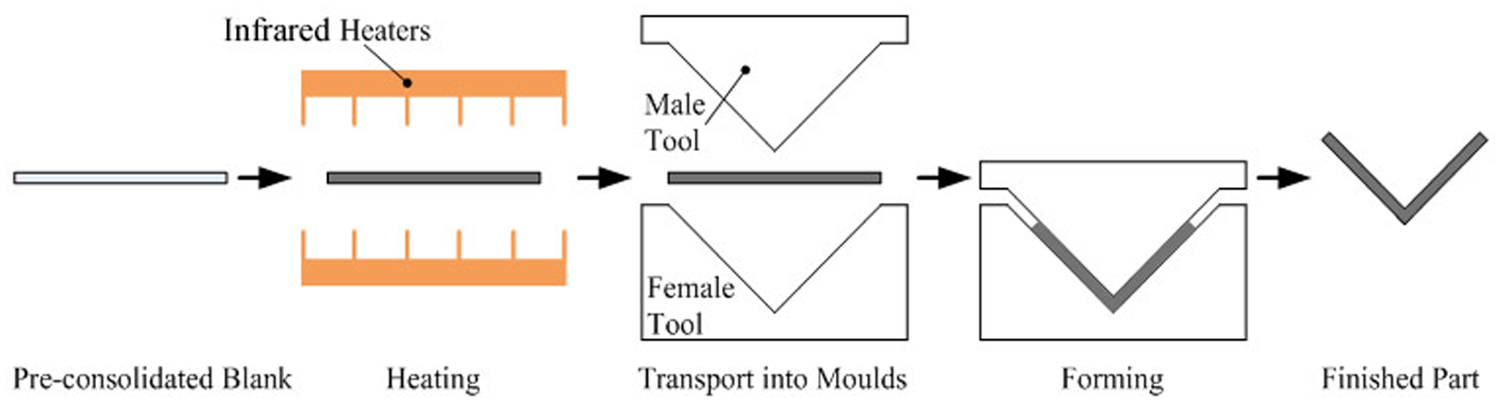
Schematic diagram of thermoforming process for thermoplastic composites.
In this work, an experimental manufacturing cell based on Lloyd Instruments L6000R Tensile Tester was developed to thermoform CFRTPs, 16 as shown in Figure 4. The manufacturing cell contains all of the major features of an industrial manufacturing setup. The system consists of a heating station, a forming station and a matched mould tooling rig. The equipment offers full control over the process by monitoring key manufacturing parameters such as tool temperature, composite material temperature and forming force. This data provides essential input data for downstream computer-based simulations of the process. In this work, the emphasis was on producing a demonstrator component that would allow the characterisation of the spring-in angle associated with changes in key process parameter settings, which led to the design and development of a V-shaped forming tooling. The matched mould tooling was designed with an open V angle of 92°; this decision was based on previous literature 17 studying on glass fibre reinforced polypropylene composites in autoclave-based forming process, where it was shown that a mould angle of 92° can produce a finished internal angle of 90°.
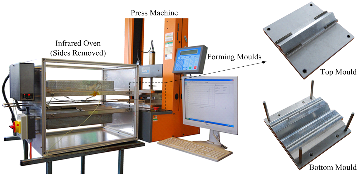
Thermoforming rig used to form 90°, V-shaped composite samples.
Experiment design
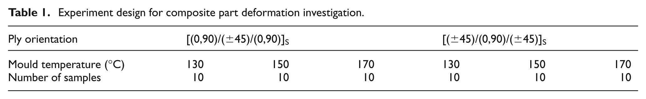
To study the deformation related to forming mould temperature and ply layup, a 90° angled component was chosen as the demonstrator geometry for thermoforming experiment. A 90° angular part is usually used as blade rib for basic structural configuration. This test sample configuration was chosen to minimise the range of geometric influences that could affect final part shape. The performance of the part during forming was based on the final angle of the finished sample relative to the original mould shape. Test samples were manufactured from a commercially available pre-consolidated thermoplastic laminate system consisting of continuous carbon fibre (CF) (T300) reinforced PPS supplied by TenCate Advanced Composites (material trade name, Cetex® PPS). The laminate supplied by TenCate consisted of six plies of woven five-harness satin CF reinforcement embedded in a PPS matrix, consolidated to 50% fibre volume fraction (Vf). Samples used for the experiment measured 100 mm × 15 mm wide by 1.86 mm thick. Two different layup configurations were investigated. These were [(0,90)/(±45)/(0,90)]S and [(±45)/(0,90)/(±45)]S, respectively. With the supplied square (1200 mm × 1200 mm) panel of [(0,90)/(±45)/(0,90)]S setup on the water jet, the [(0,90)/(±45)/(0,90)]S samples were cut along the panel edge directions, while the [(±45)/(0,90)/(±45)]S were cut by rotating 45° of the feed direction of water jet.
Six scenarios with the two different layup configurations and three different mould temperatures were tested, as shown in Table 1. Ten samples are made using the thermoforming equipment for each scenario. The number of sample is decided based on the SD of values for items tested and the required precision of the average value 18

Experiment design for composite part deformation investigation.
in which σ is the SD of the property in the lot and δ is the required precision of the average value. The objective is that the error in the average due to sampling should almost certainly be less than δ. For a ±0.1° precision requirement, the number of sample was selected as 10 based on test results in this thermoforming experiment.
Forming procedure
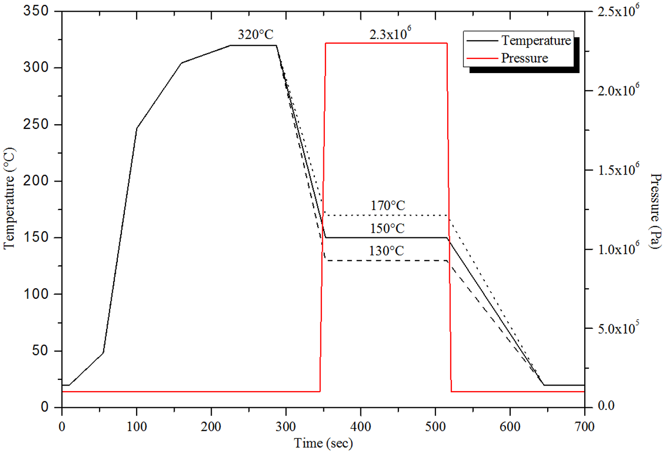
According to processing guideline, 15 the laminate sample was heated between infrared heating panels to the forming temperature of 320 °C. The samples were held in the oven until the centre of the laminate reached the forming temperature (measured by thermocouples); this took approximately 60 s. Once heated, the sample was transferred into the forming system where it was shaped to the geometry imposed by the mould tool. The forming pressure applied in the experiment was 2.3 MPa (the suggested pressure in the guideline is 2–4 MPa, facility dependent). The part was maintained at a constant temperature provided in the moulds for 180 s (60–180 s suggested in the guideline) after transfer and before demoulding. During the whole thermoforming process, the temperature of the composite sample is monitored and recorded using an eight-channel thermocouple universal serial bus (USB) data acquisition module with sampling interval of 2 s. The probe of thermocouple is plugged in a pre-drilled 1-mm hole on the centre of sample and fixed using heat-resistant tape. A temperature profile for a sample formed with a 170 °C mould temperature is shown in Figure 5.
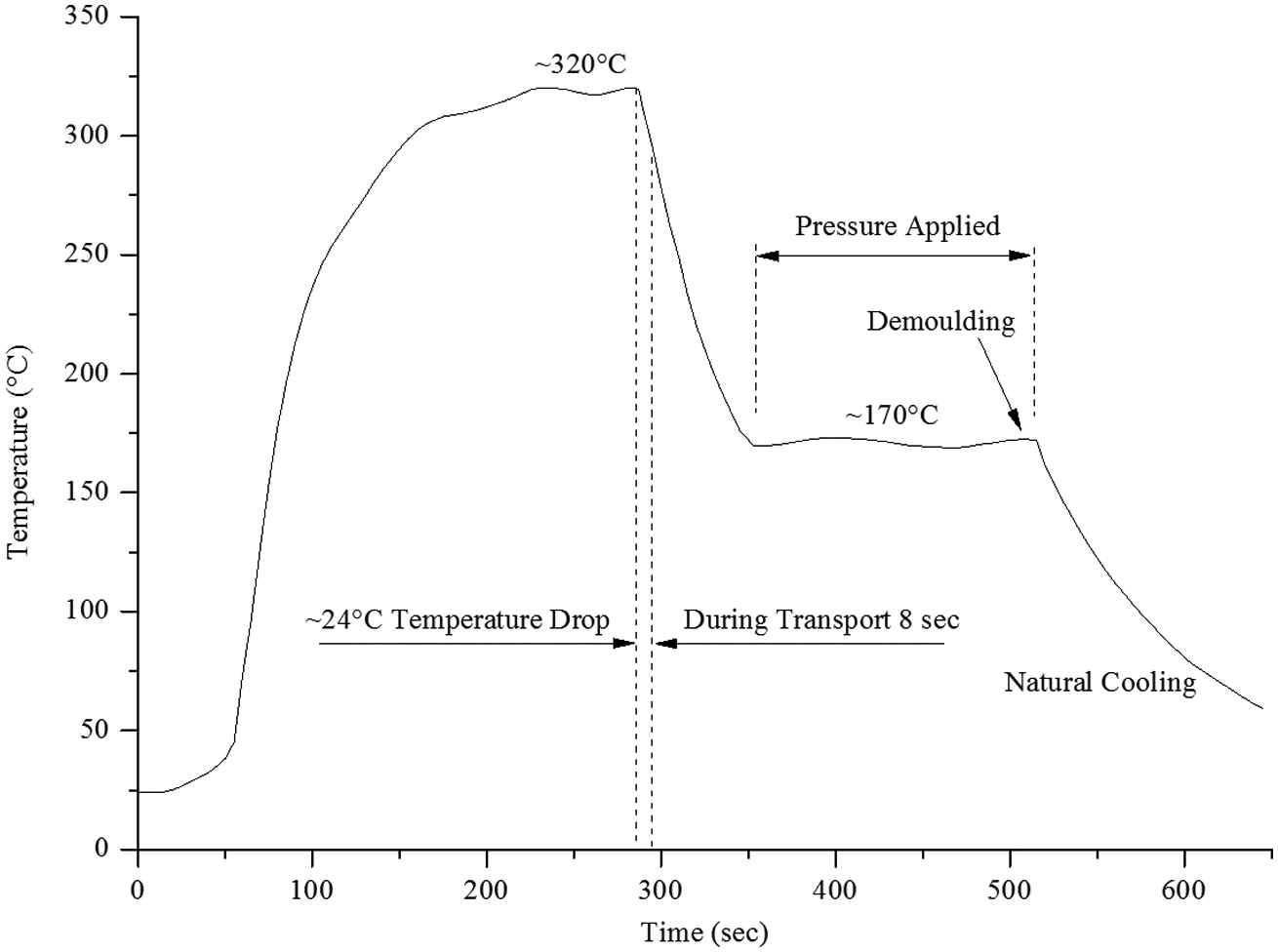
Temperature profile measured for a sample during thermoforming experiment.
After forming, the composite parts are trimmed to their final shape to release any residual effect caused by the unformed edges; these were included to allow for sample alignment and constraint during forming, as shown in Figure 6.
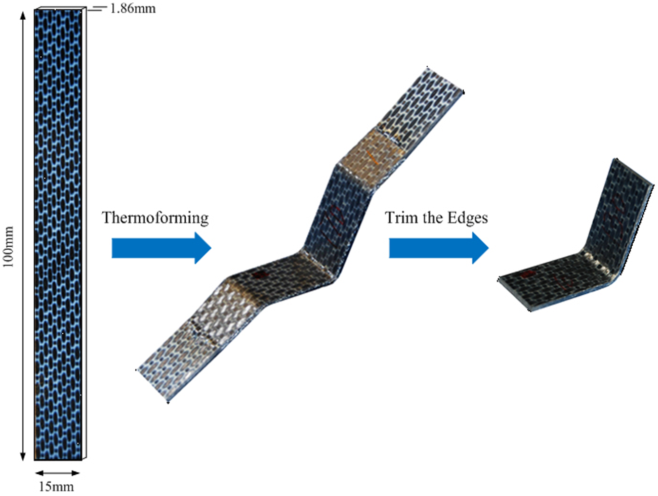
Experimental sample thermoformed from pre-consolidated laminate to V-shaped final part.
Sample inspection
Inspection of the finished part geometries was carried out using a coordinate measuring machine (CMM). CMM is a 3D device for measuring the physical geometrical characteristics of an object. The CMM used in current work is Brown & Sharpe MICROXCEL PFX with 0.5 µm accuracy. This machine can be both manually and computer controlled. Measurements are defined by a probe attached to the third moving axis (vertical) of this machine.
Both the inner surface and the outer surface angles were measured for each sample. For each side of V-shaped parts, the angle was calculated using two planes, which were defined using 20 sample points on each surface. This facilitated the accurate determination of the sample angle avoiding the possibility of errors arising from single angular measurements, which would have been possible using a vernier protractor, for example. The measurement of multiple surface points also facilitated the creation of 3D CAD models representing the test samples.
Simulation model setup
A 2D approach 12 has been applied to the analysis used for part shape prediction using COMPRO, which is a commercially available simulation platform. It is equipped with capabilities that enable the consideration of process parameters as a part is formed, so that final geometric form can be determined. Primarily developed for thermosetting material systems, the analysis in this case was modified to take account of the thermoplastic properties of the test material. Stress/deformation module is employed in the finite element (FE) method to solve for the component state variables during processing.
The basic work equation of the FE displacement method is 19
where the left side of the equation is the total internal virtual work and the right side of the equation is the work done by both body forces and surface forces over displacements u. In COMPRO, the 2D displacement field can be denoted as {u w} T , the body forces are denoted as {pvx pvz} T and the surface tractions are denoted as {psx psz} T .
Using this method, the classical FE equation involved in the stress/deformation module can be derived as 20

where
In COMPRO, the equation (3) is solved through Gaussian elimination. And the final coordinates of deformed structural nodes can be obtained based on original coordinates and displacement results.
The 2D plane strain four-node quadrilateral elements were employed to represent the experimental sample and mould section (see Figure 7). As the cross section is symmetric, only half of the section was modelled. Boundaries of the part and tool are set as convection for heat transfer. The bottom mould is defined as fixed with no displacement. The nodes on symmetry line of the part are set as sliding with no displacement perpendicular to the boundary. The start pressure is set as 0.1 MPa, and the initial and final temperature is set as 20 °C.
Finite element model representing one-half of the V-shaped test sample.
Material model in COMPRO indicates which materials are to be used in each of the model regions and descripts the properties to be associated with each material. In current case, the V-shaped part is assumed as deformable and the mould tools were considered as rigid parts. Both the top and bottom mould materials are made of aluminium, and the formed V-shaped component is CF reinforced PPS composites. The properties of the aluminium, CF and PPS materials at room temperature are shown in Table 2.
Material properties.
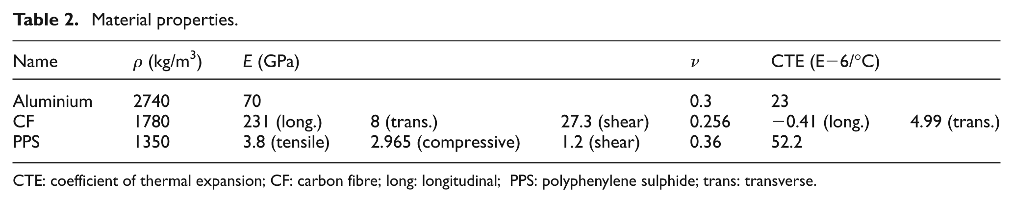
CTE: coefficient of thermal expansion; CF: carbon fibre; long: longitudinal; PPS: polyphenylene sulphide; trans: transverse.
For each composite material region, the number, thickness and orientation of the plies within that region were defined. The woven fibre (both plain and five-harness satin) reinforced laminate in the experiment is represented using unidirectional layups, 21 as shown in Figure 8.

Representation of fabric laminate.
In order to simulate the forming condition used for the experiment, a batch of simulations was executed with different process cycle models (130 °C, 150 °C, 170 °C forming temperature, respectively) and ply layup configurations ([(0,90)/(±45)/(0,90)]S and [(±45)/(0,90)/(±45)]S), which reflect the range of experimental mould temperatures and fibre orientations detailed earlier in this section. The process cycle model simulating the experiment is shown in Figure 9.
Process modelled in COMPRO for sample forming conditions.
Data transfer to CAD environment
The deformed part shape predicted using the simulation was transferred to the computer-aided three-dimensional interactive application (CATIA) CAD environment using a custom built visual basic interface, using the steps shown in Figure 10. The points shown in Figure 10(a) were located using the post-forming nodal positions from the FE model processed using COMPRO. Splines and lofts were then fitted to the points, and surfaces were extruded from the sectional data. The upper and lower surfaces were then blended to form a solid CAD model. This shows how simulated part forms could be transferred to the digital environment for the purpose of assembly validation in digital manufacturing techniques.
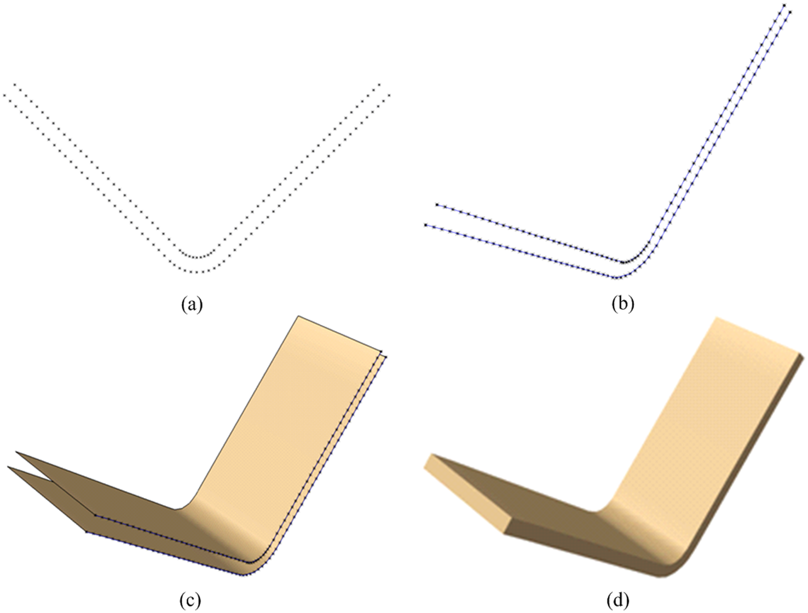
Simulation of predicted deformed part shape modelled in CAD environment: (a) simulated result, (b) fitted splines, (c) 2D surface and (d) 3D solid part definition.
Results
Finished sample angles
The final sample angles are shown in Figure 11. For parts formed using the [(0,90)/(±45)/(0,90)]S ply orientations, the parts cooled from an initial mould temperature of 170 °C were closest to the intended 90 ° part angle (90.53° average angle), followed by the 150 °C (90.66° average angle), and 130 °C (91.15° average angle), conditions in sequence. For samples with the [(±45)/(0,90)/(±45)]S ply orientations, the samples cooled from an initial mould temperature of 150 °C were closest to the intended 90° part angle (90.05° average angle), followed closely by the 170 °C (89.90° average angle), and 130 °C (90.22° average angle), conditions in sequence. These results also show that the [(±45)/(0,90)/(±45)]S ply orientation will result in a sample angle that has less variability across temperatures than the [(0,90)/(±45)/(0,90)]S configuration. This is also illustrated in Figure 12 where the [(±45)/(0,90)/(±45)]S sample angles across the three mould temperatures. The mould temperature of 150 °C with a ply configuration of [(±45)/(0,90)/(±45)]S will give a finished part angle, which is closest to the required 90°. These outcomes illustrate the importance of deformation prediction in composite part manufacturing. Compared with the mould tooling, which was designed with an open V-shaped angle of 92°, the different combinations of material and processing conditions tested here have resulted in final part angles ranging from less than a 1° to more than a 2° difference from the original mould angle. The [(±45)/(0,90)/(±45)]S laminate with 150 °C mould temperature should be applied if the design intent for the V-shaped angle is 90°.
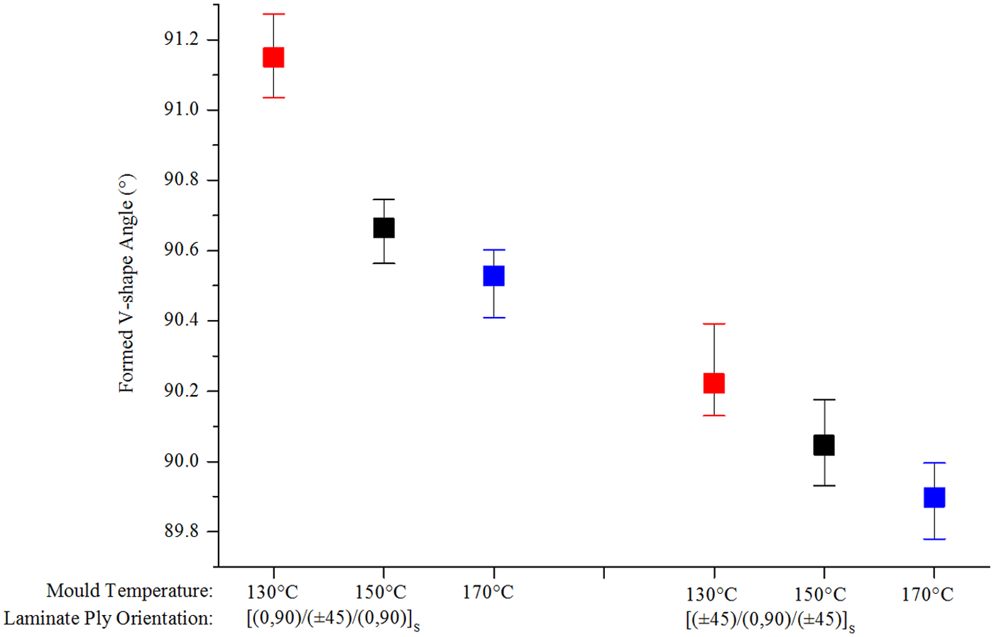
Measured V-shaped angle for three mould temperatures and two layup configurations.
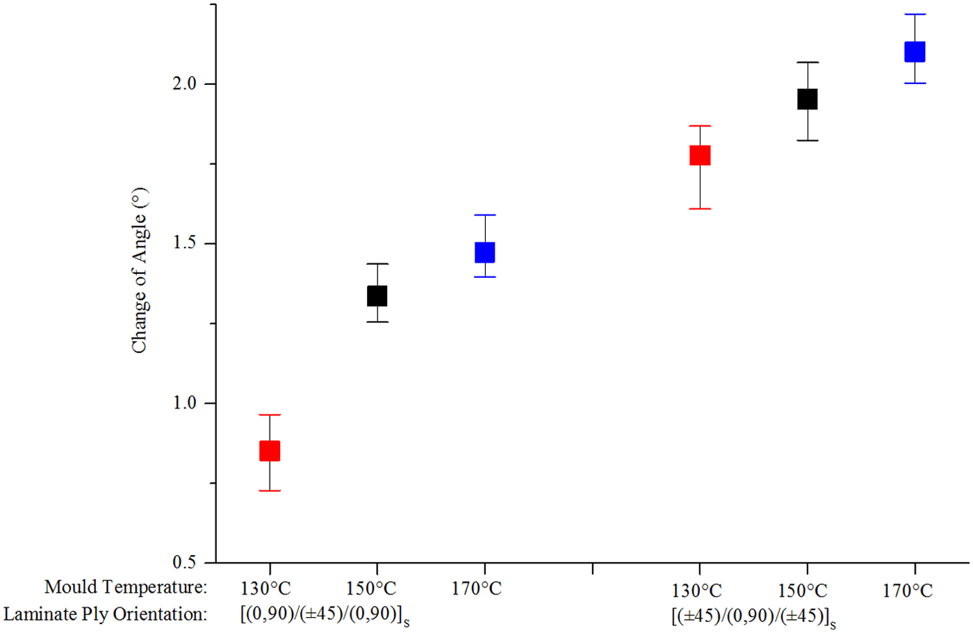
Change in V-shaped angle relative to original mould angle.
Differential scanning calorimetry measurements
The degree of crystallinity (DoC) of the formed CF/PPS V-shaped component was also inspected through differential scanning calorimetry (DSC). This was carried out to examine the crystallinity level within the polymer matrix, which is affected by the cooling rate and is an important processing condition affecting residual stress formation. 22 For this work, although the mould temperature can be set as constant, the cooling rates during both cooling stages (forming temperature to mould temperature and mould temperature to room temperature) are not fully controlled. The DSC results show all the samples formed by different mould temperatures crystallise at a similar level (∼26%).
Simulation of 90° sample forming process
COMPRO output files are written in a text format and give the value of all major state variables at every model node or element at process cycle time intervals specified in the control file. In current case, only the final nodal coordinates of the nodes on top and bottom side boundaries of the composite part need to be exported to identify the spring-in deformation. By connecting these points, the deformed boundary profile can be created, as shown in Figure 10(b).
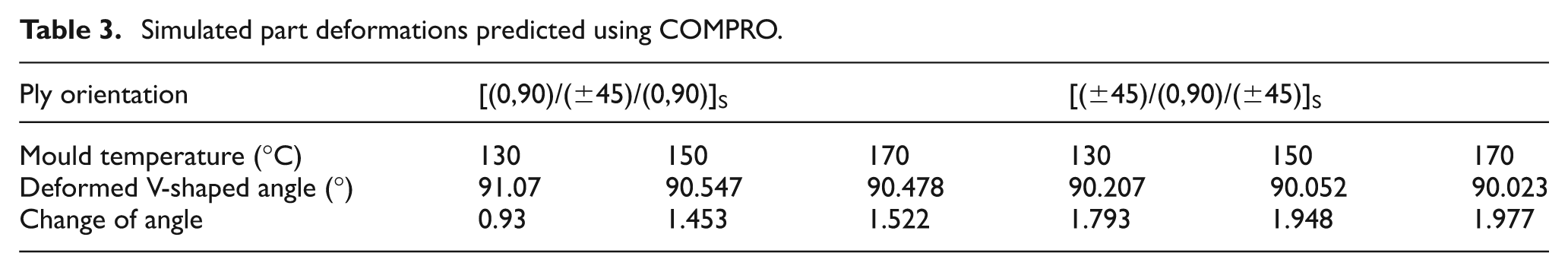
The results of the batch simulations carried out to re-create virtually, the test conditions for the sample forming processes, are shown in Table 3. These results again demonstrate that deformations will arise for the composite angles as they are formed and that the shape variation is dependent on material configuration and processing conditions. The predicted results also indicate that it is better to use [(±45)/(0,90)/(±45)]S than [(0,90)/(±45)/(0,90)]S material in current thermoforming rig to achieve 90° final part angle.
Simulated part deformations predicted using COMPRO.
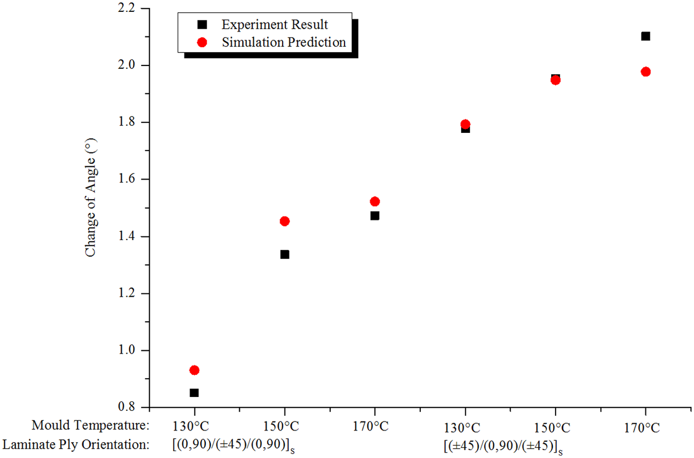
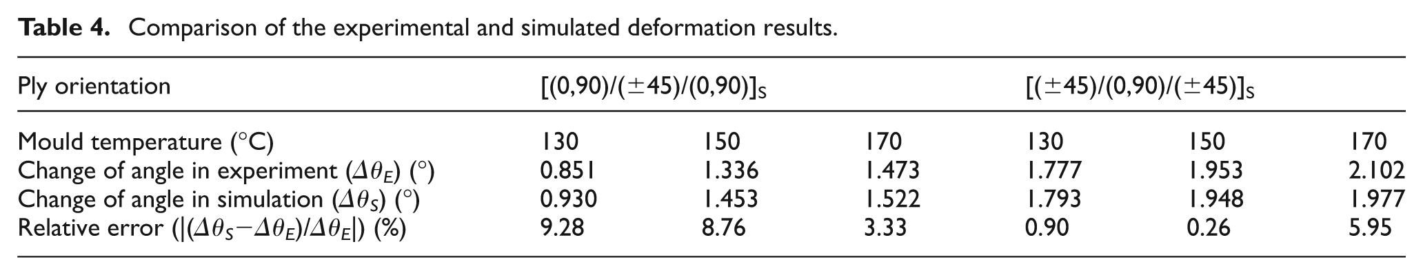
A comparison of the experimental and simulated results is presented in Figure 13 and Table 4. With a less than 10% relative error across all cases, the simulation predicted deformation is in general agreement with the experimental results detailed in the previous section. The largest difference between experimental and simulated results was 9.28% for the [(0,90)/(±45)/(0,90)]S layup configuration at the 130 °C mould temperature, whereas the simulation outcome for the [(±45)/(0,90)/(±45)]S configuration was within 0.26% of the experimental result for a mould temperature of 150 °C.
Comparison of the experimental and simulated deformation results.
Comparison of the experimental and simulated deformation results.
To validate the proposed method in this work, finite element analysis (FEA) tool Abaqus was also used to predict the part deformation and compare with the COMPRO simulation. The finished part form was exported to CAD system for deformation inspection and further digital manufacturing applications. The angle of simulated part was inspected in CATIA CAD environment using mesh nodes transferred from Abaqus. Figure 14 shows the thermoforming simulation process modelled in Abaqus, and Table 5 presents the comparison of experimental and simulated results for V-shaped composite part thermoforming. These results again demonstrate that deformations will arise for the composite angles as they are formed.
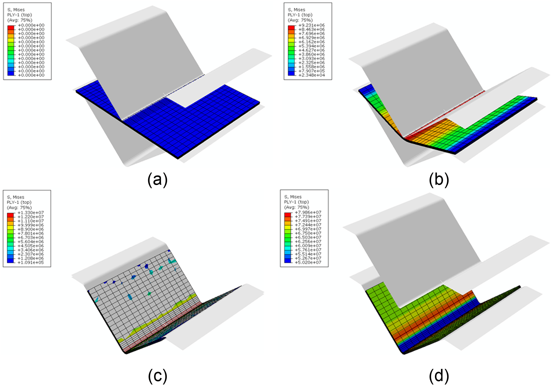
Simulated thermoforming process modelled in Abaqus: (a) initial contact, (b) press forming, (c) clamp and (d) demoulding.
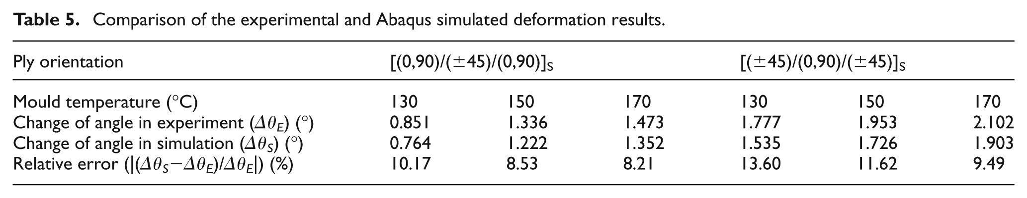
Comparison of the experimental and Abaqus simulated deformation results.
For Abaqus, the FEA results were stored in an output database from the start to the end of the thermoforming simulation. An orphan mesh part instance can be imported from any increment/step available in the output database. The orphan mesh part contains no feature information and is extracted from the output database as a collection of nodes, elements, surfaces and sets with no associated geometry. By choosing the last frame of demoulding step of the analysis, the finished part was imported as an orphan mesh in the Abaqus part module. Then orphan mesh part was exported as a 3D XML file for use in the CATIA CAD environment. The part can be used as a typical geometric component instead of an orphan mesh part after its solid feature is reconstructed in CATIA using nodes information in the 3D XML file. Figure 15 shows the predicted V-shaped part transferred from Abaqus to CATIA.
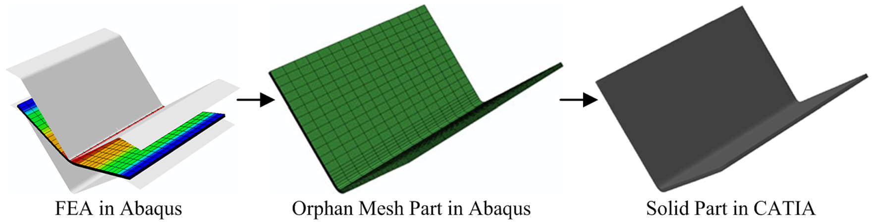
Abaqus predicted deformed part shape transferred to CAD environment.
Discussion
The main aim of this work was to develop a means by which virtual methods could be used to predict the behaviour of a CFRTP part, so that more realistic component forms could be employed during simulated build validations in a digital manufacturing environment. The approach was motivated by the need to promote more sustainable solutions for advanced material applications in future transport systems. This can potentially be achieved through the development of material systems and processing methods supported by predictive technologies in both product and process designs. The work aimed to identify the effects of processing parameters including material system (layup angles) and processing conditions on the finished dimensions of an angled composite component, thereby informing design and production-related decisions including material configuration and mould design. To achieve this, the deformation behaviour of a 90°, V-shaped, thermoplastic composite angle was examined using experimental manufacturing and inspection methods. FE methods were used to determine how the finished part angle varied using virtual simulations. A simple angular form has been used for the work to narrow the range of geometric influences, which could affect final part shape. The simulated results have been compared with practical tests to validate the tools and methods used.
The experimental results arising from this work demonstrate that there is process-induced deformation ranging from 0.851° to 2.102° in V-shaped parts formed with six-ply ([(0,90)/(±45)/(0,90)]S and [(±45)/(0,90)/(±45)]S) laminates. This behaviour is caused by the composites’ anisotropic shrinkage during thermal processing cycle, and it is difficult to predict using formula calculations. 23 The various results also illustrate that the final angle of thermoformed CFRTP part is correlated to processing conditions and material configurations. Thus, it is possible to control the post-forming part angle to achieve tolerance requirement by customising the processing conditions or layup configurations. The influence of mould temperature on the deformation is more dependent on the composite’s thermal properties and the deformation is caused by the thermal shrinkage through the range of temperatures as the samples cool.24,25 As the three sets of tests (130 °C, 150 °C and 170 °C) used set the mould temperature above the sample’s softening temperature (90 °C), the residual stress arose during the shrinkage process as the sample transitioned from forming temperature to mould temperature. This can still be largely relieved during the forming stage when the part is confined to the mould. After demoulding, the part deforms because of the thermal shrinkage during the cooling from mould temperature to room temperature. The samples formed using the 170 °C mould temperature will generate more shrinkage when cooling to room temperature, followed by 150 °C and 130 °C, respectively. Therefore for the same ply orientation, the final bend angles decrease with the increasing mould temperature (see Figure 11). For different layup configurations with the same processing conditions, the mismatch between CF and PPS matrix shrinkage through the sample thickness is similar as they have the same number of plies and fibre volume fraction. The out-of-plane contraction for the laminates is much larger than the in-plane contraction. Therefore, the reason for lower level of deformation with [(0,90)/(±45)/(0,90)]S layup samples should be the predomination of fibres along the length of the V-shaped part, which bear the out-of-plane contraction stress. The effects of mould temperature and layup configuration on final part form in the experiments show that less deformation arises in samples where fibre orientation is dominant along the angle cross-sectional direction and more deformation arises in samples where a higher mould temperature has been used.
Ignoring process-based dimensional variations by using the nominally sized CAD model for build validation could cause longer assembly times or tolerance failures at best or costly redesign at worst – if mal-formed composite parts are released for assembly. An example is shown in Figure 16. The ‘as-designed’ form includes nominally sized features with perfect 90° angles and the formation of the rib with two back to back angled sections is not a problem. The simulated CAD form, however, now takes into account processing conditions and material configuration, and in predicting the final part angles, it is more representative of the final ‘as-manufactured’ form. The application of the 90° experimental geometry in the formation of a rib section shows that the slight variation in the angular pieces has meant that the assembly requirement for the angles to be placed back to back is not possible without the use of fixturing to force the components into the required position. It is at this stage that the designer can re-run his or her simulation to obtain optimal part forms by changing process parameters. Alternatively if fixturing is the only solution, the designer can examine the effect of fixturing forces on the parts, so that the assembly can be completed with minimal impact on any residual force on the components.
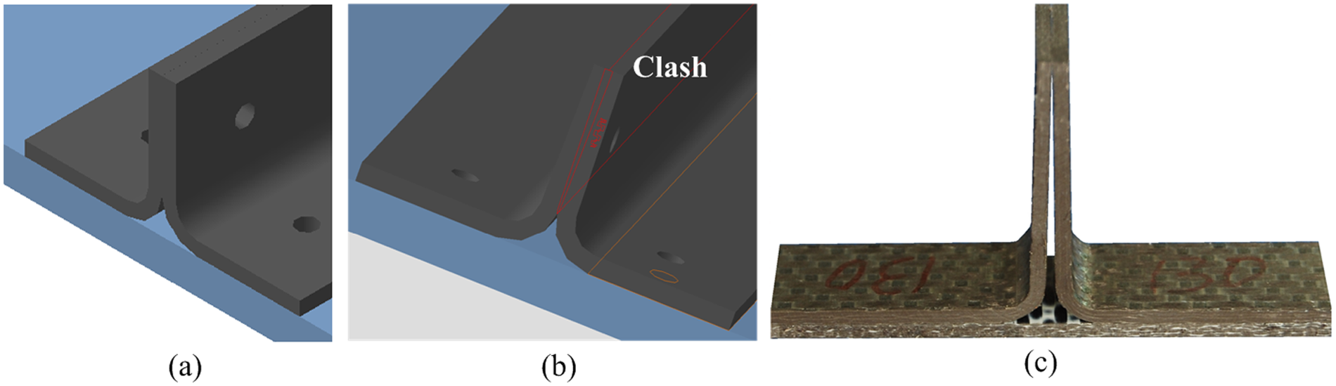
Assembly problem caused by unplanned part deformation in composite rib section: (a) as-designed form, (b) simulated part form and (c) as-manufactured form.
The fundamental motivation for this work comes from the growing need to develop advanced structural composite applications in a digital manufacturing environment. Furthermore, the function of digital manufacturing, in simulating and validating product manufacturability, is based on the prerequisite that the digital models used in the software systems represent realistic part forms. As a typical feature of composite part manufacture is process-induced shape variation, there is a need for assembly process simulation methods that can predict realistic composite geometries for design purposes, which can be delivered to the digital environment for component build validation during assembly planning.
This work has achieved this aim by proving that the simulated part performance for a simple 90° sample can be predicted accurately using FE methods. The FE outcomes can be translated into 3D part definitions, which in turn can be delivered to the digital manufacturing environment. The relationship between layup configuration and mould tool temperature has also been established. It can also be concluded that the final part dimension can be controlled by using the material configuration and mould temperature when using the current thermoforming rig.
Conclusion
The work shows how manufacturing simulation techniques, which have been used mainly for metallic-based component assembly, can be extended to composite applications facilitating the use of realistic part form predictions for build validation simulations. An effective simulation method has been established to predict the deformation behaviour of a thermoplastic laminate composite as it is thermoformed. A comparison across a range of physical tests has shown that at worst, the simulated results for the prediction of the finished angle in a simple 90° angle are within 10% of the practical test measurements. By transferring predicted results to CAD environment, this method can deliver ‘as-manufactured’ part shape to digital manufacturing system for more realistic assembly validation.
Footnotes
Acknowledgements
We acknowledge the contribution of Convergent Manufacturing Technologies, Inc. in providing the COMPRO package, which was used to carry out the simulation work for this study.
Declaration of conflicting interests
The authors declare that there is no conflict of interest.
Funding
This work is part of a broader programme ‘Improving the Sustainability of Transport Using Advanced Composites and Digital Manufacturing’ supported by the Department of Employment and Learning (Northern Ireland).