
Abstract
Large-aperture diffraction gratings are the key elements for high-power petawatt-class laser facility. At present, it is difficult to directly manufacture high-accuracy large-aperture gratings by using ultraprecision manufacturing techniques. Mechanical tiling technique with segmented gratings can be employed to cope with the challenge in large-aperture grating manufacturing. In this article, a novel tiling and adjusting device for obtaining large-aperture gratings was proposed and built to overcome the challenges in developing a Big Science Facility. The idea of integrated design and precision analysis has been introduced into the design process of the device. The theoretical analysis on static and dynamic characteristics has been conducted on the key components of the device by using finite element method. Under a series of mechanical tests, the performance of the large-aperture grating tiling and adjusting device developed was evaluated against the industrial requirements. The testing results show that the device has the positioning precision and stability in light of the design specifications. The results also indicate an optimal linear accuracy of 20 nm and a rotational accuracy of 0.4 µrad being achieved at the device.
Introduction
In high-energy laser field, grating is usually a dispersive optical element with well-regulated microgroove structures or actinic materials. Currently, large-aperture grating has become the key element for many Large Science Projects, such as deep space exploration program, astronomical telescope and inertial confinement fusion (ICF). However, the ever-increasing aperture of diffraction gratings, which is often required in optics-related Large Science Projects, has restricted its development for application. The impractical technique and its high cost are the main bottleneck for manufacturing large-aperture grating directly. Tiling technology will be a cost-effective method for solving the problem. At present, two approaches can be employed in the tiling of large-aperture grating, that is, mechanical tiling and optical tiling in fabrication. Optical tiling in fabrication can be described as a grating structure tiled by using holographic diffraction or scanning beam interference lithography. Mechanical tiling technique is tiling small grating segments into large grating by using ultraprecision positioning technology. The new attempted tiling technique becomes a perspective trend for obtaining large-aperture grating. The grating tiling technology can be dated back to the nineties of last century. Richardson Grating Laboratory successfully replicated a small-sized mosaic of two gratings onto a single blank, which was used in European Southern Observatory (ESO). 1 Recently, a vacuum-compatible grating-inspection system was also developed to monitor the change of the compressor-grating-surface feature on the tiled-grating device of OMEGA-EP. 2 Tiled-grating technology also gained much attention in terms of tiling aperture and accuracy.3,4 The mount system for segmented grating was also developed for the requirements of FIREX-1. 5 Generally, tiling method is a practical technique for achieving the petawatt (PW) regime in chirped-pulse amplification (CPA) laser system, such as the high-power laser system, POLARIS, Shenguang II and the national civilian facility, LULI.6–8 So far, grating tiling technique has become a paramount approach for achieving large-aperture grating. Although the accuracy can reach to sub-nanometer for some micromotion devices, it is hardly directly used in the industrial application due to their stability, reliability and even size limitation. 9 Piezoelectric actuator was generally adopted in some positioning systems. Li and Xu 10 analyzed the kinetostatic model and developed a decoupled XY stage to achieve scale accuracy in submicrometer. Zareinejad et al. 11 developed a macro-/microteleoperation system using piezoelectric actuator and analyzed the theoretical model. Sun et al. 12 presented a macro-/micro-driven XY-stage positioning system for nanoelectromechanical system (NEMS). However, the positioning devices developed, which were either simplified to one or two directions or lacking necessary stability and accuracy, cannot be used for the actual application of large-aperture grating. The increasing demands for aperture, accuracy and stability in high-energy laser system require a novel and practical implementation for the mechanical tiling and adjusting device. In this article, the tiling technique for large-aperture grating was introduced and developed for the application of CPA technology. The testing results obtained show that the design idea and key techniques are qualified for the engineering applications of tiled-grating.
Design of the grating tiling and adjusting device
Motions in the grating
The compressor system for laser includes four sets of tiled-gratings, and two of them can form a Treacy grating pair.
13
The aperture for each set of tiled-grating was 1220 mm × 350 mm. As shown in Figure 1, each set of tiled-gratings included three subgratings, in which the middle one was a standard grating and the other two were nonstandard gratings (NSGs). The directions of groove pattern on the grating surface were in the linear Y-direction, in which the NSGs need not be tiled. Therefore, 5 degrees of freedom (DOFs) of each grating should be involved in according with the standard grating, that is, lateral shift
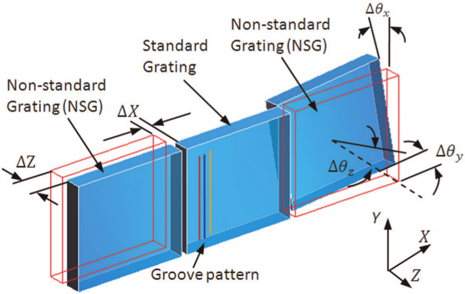
Schematic diagram for the movements of tiled-gratings.
Design motivations underlying the tiling and adjusting movements and their implementation
Conceptual design for the movement system
The mechanical device intends to be designed including tiling and adjusting subsystems, with which the segmented gratings and their entirety can move in parallel and serial mechanisms. As presented in Figure 2, the movement of grating in each set of tiled-gratings was parallel driven by five drivers in the tiling subsystem. The movement combination of various drivers accomplished the required DOFs for NSGs. For example, the combined movements of drivers 2, 3 and 4 in Z-direction and minor compensating movements of drivers 1 and 5 could realize
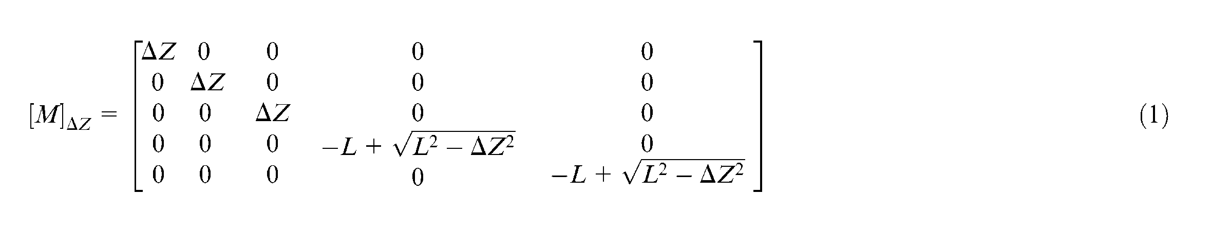
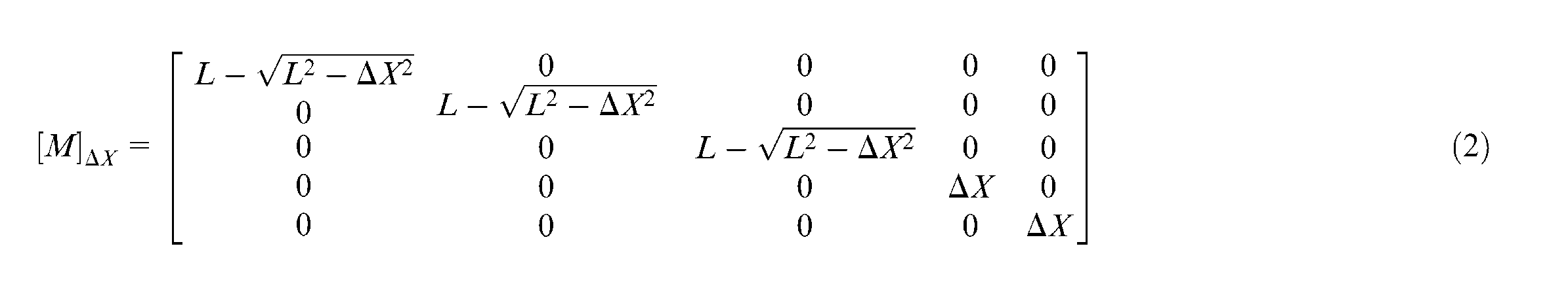
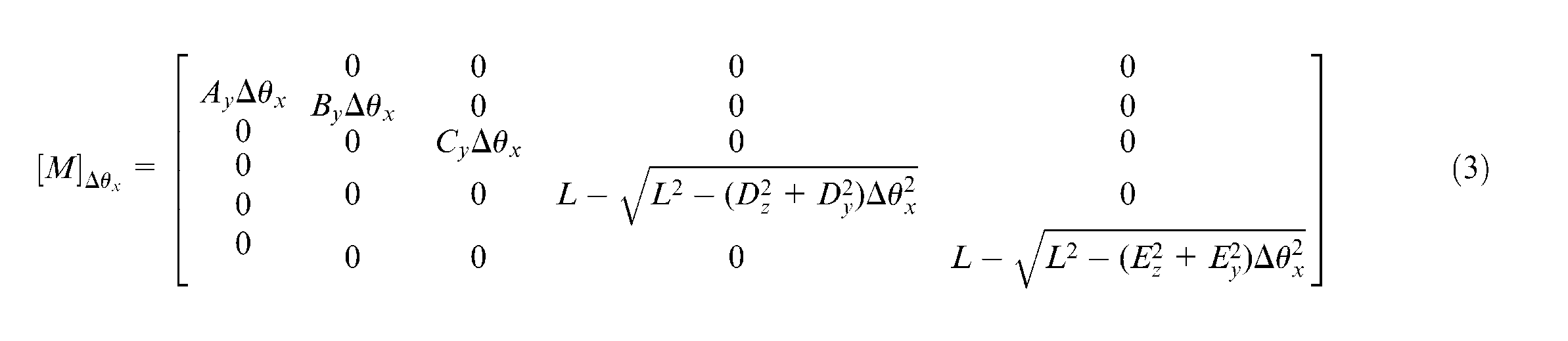
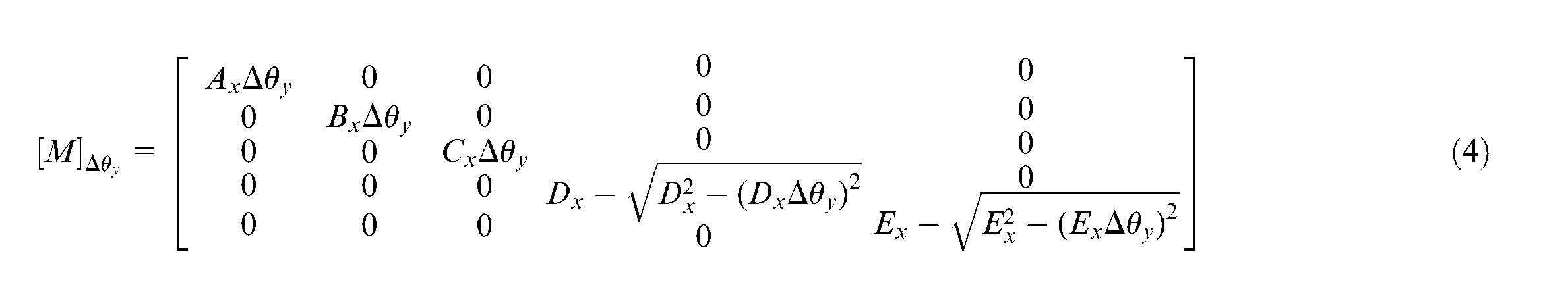
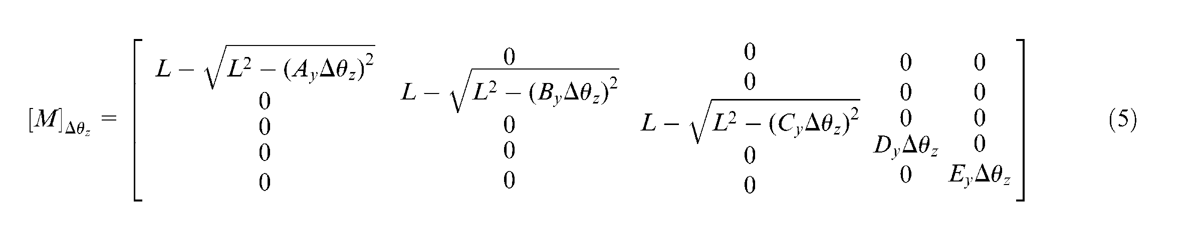
where L is the effective length of the flexure joint and
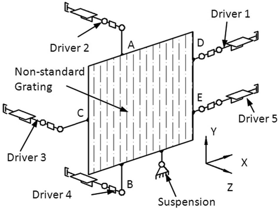
Schematic diagram for the driving system of single grating (NSG).
The adjusting subsystem accomplished the integral movements for each set of tiled-gratings, positioning the Treacy grating pairs with the other set of gratings in the grating compressor chamber (GCC). As the requirement of stability and precision, serial decoupling mechanisms were carefully considered in the design of adjusting subsystem. Moreover, compact space should also be taken into account in the process of integrated design because of the limited space of GCC. Figure 3 shows the movement of adjusting subsystem for one of the grating sets. With the design strategy, the grating group could be moved in series in the required 4 DOFs, that is,
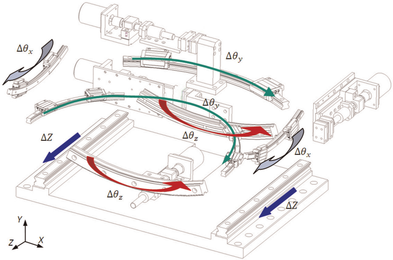
Movement of adjusting subsystem.
Design and analysis of the key components
The key mechanical components in the device are crucial for the movement implementation of the tiling and adjusting device. Based on the finite element analysis (FEA), the mechanical frame, the driving actuator and the flexure joint and the flexible hinge are discussed in terms of the accuracy, stiffness and their actualization.
Mechanical frame for the tiling subsystem
The mechanical frame was the base part for the tiling subsystem, on which all the drivers and gratings, whether moved relatively or not, could be mounted. Thus, the mechanical frame was a crucial part for the grating system. In order to ensure the final performance and feasible processing technique, the frame was designed to be assembled with machined stainless steel plate. The static deformation of mechanical frame caused by gravity and calculated by ANSYS® is presented in Figure 4. It was indicated that the maximum static deformation of the designed mechanical structure is about 0.5 µm. The deformation caused by gravity in Y-direction was not sensitive to the final tiling quality. Albeit it was nonsensitive, the analysis underpinned the high structural stiffness and optimal layout of the mechanical frame in tiling subsystem.
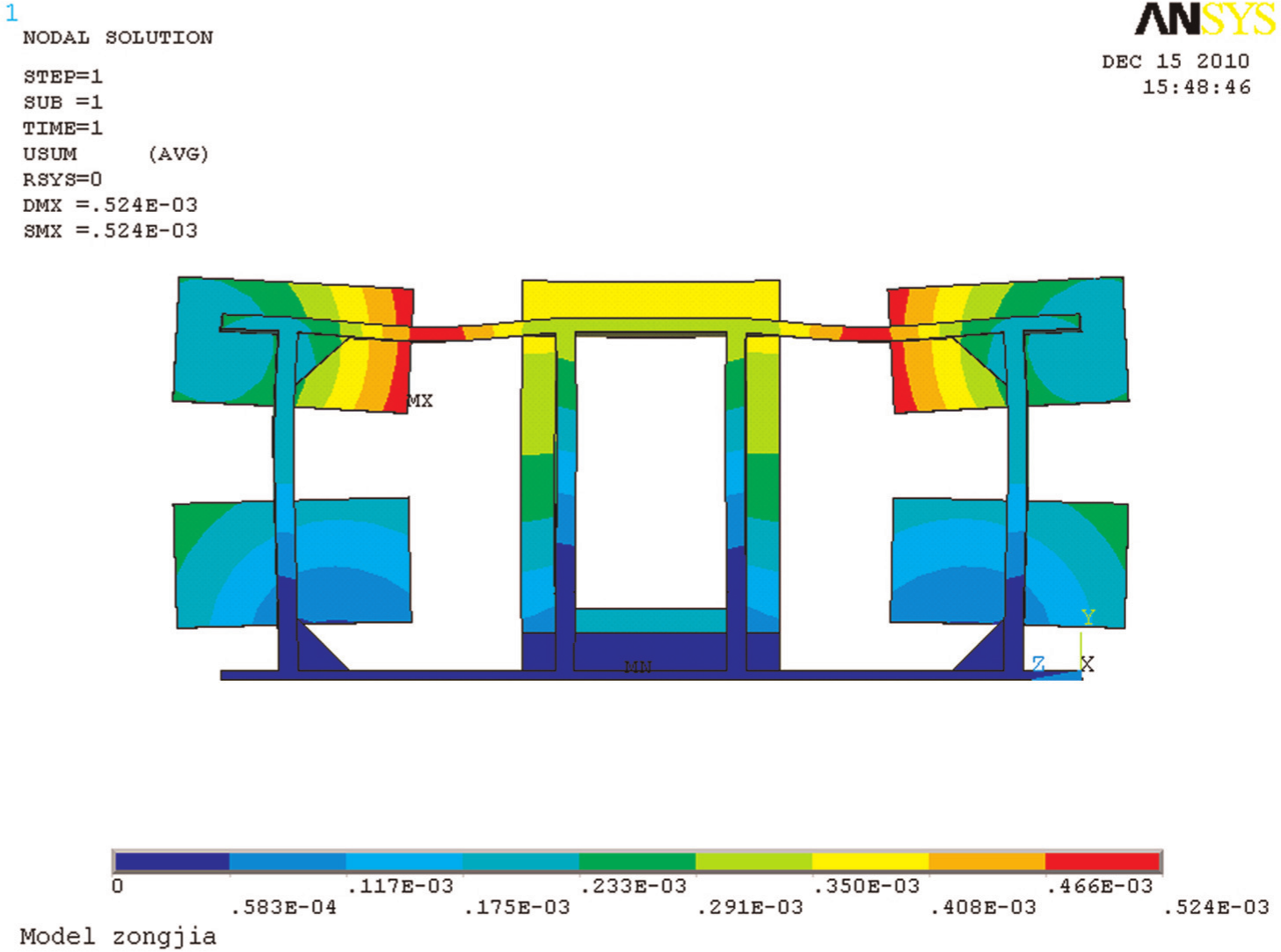
Static deformation of mechanical frame.
Driving actuator for the tiling subsystem
In the macro-/microdriver, DC motor combined with piezoelectric actuator composes the key driving element of the movement system. The sketched model for one of the macro-/microdrivers is shown in Figure 5. The preparatory adjustment of single grating was accomplished by the macromovement, that is, the combined movement of step motor, coupling, ball screw and linear motion guide. The macromovement could be locked by a manual mechanism after its moving range went into the positioning range of micromovement. Thereafter, the micromovement could start under the instruction of centralized controller. The micromovement was mainly achieved by the piezoelectric actuator, the flexible hinge and the flexure joint. The piezoelectric actuators (Model PI845.30; PI Company, Germany) with high closed-loop resolution of 0.9 nm were employed in the micromovement for positioning the NSG in nanometer scale.
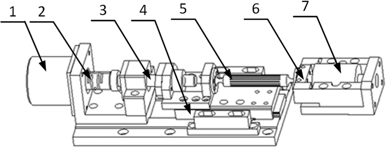
Macro-/microdriver for the tiling subsystem.
The flexure joint and the flexible hinge
High stiffness and flexibility should be considered in the design of flexure joint in the tiling system. For the NSGs, stiffness in flexure joint is one of the key factors for the stability. The flexibility of flexure joint also ensures that it can be driven by the piezoelectric actuators under the layout of the nonstandard parallel mechanism. The result of von Mises equivalent stress (SEQV) is shown in Figure 6(a). With the novel design of the necks and through slots on the flexure joint, the balance between stiffness and flexibility was able to be achieved in the designed structure. By dividing certain loading by its deformation output, the stiffness could be identified as 0.04 N/µm in radial direction (Y) of the flexure joint. The calculated stiffness could also be used for determining the torque of DC motor.
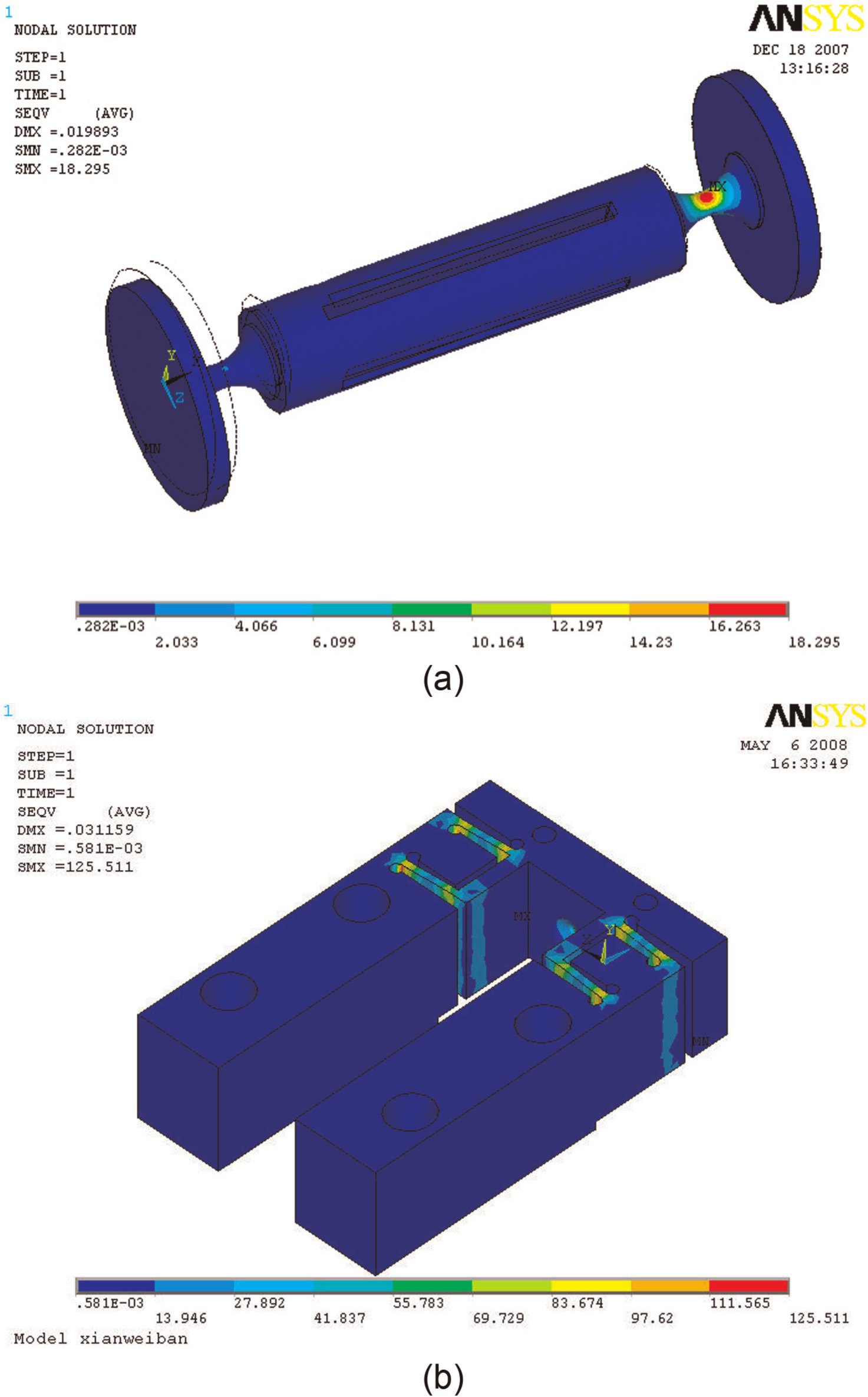
Stress analyses of the flexure joint and the flexible hinge: (a) von Mises equivalent stress distribution of the flexure joint and (b) von Mises equivalent stress distribution of the flexible hinge.
The flexible hinge was an elastic element for the movement of piezoelectric actuators. Sufficient stiffness of the flexible hinge can fulfill the preloading of piezoelectric actuators and also ensure the movement precision in micromovement. Carefully designed microslot structures were distributed on the flexible hinge. The stress analysis result of the flexible hinge is shown in Figure 6(b). According to the preload and the deformation value from the FE analysis result, it was indicated that the maximum stiffness in Z-direction was 30 N/µm.
System integration for tiling and adjusting subsystems
Using the FEA results, the key dimensions of the grating tiling device have been determined. As shown in Figure 7, the three-dimensional (3D) geometry model of the grating tiling device is presented with Pro/ENGINEER® Wildfire software. The profile size of the mechanical structure for grating tiling device was 1222 mm × 653 mm × 885 mm. The whole mass for the mechanical structure was estimated to be 780 kg. Two NSGs to be tiled were mounted on the frame by using five macro-/micromovement drivers. The standard grating and the whole tiling subsystem were mounted on the adjusting subsystem, which can provide movement and adjustment in the 4 DOFs. The mechanical model with the integrated design demonstrated the properties of compact layout, proper stiffness and high precision.
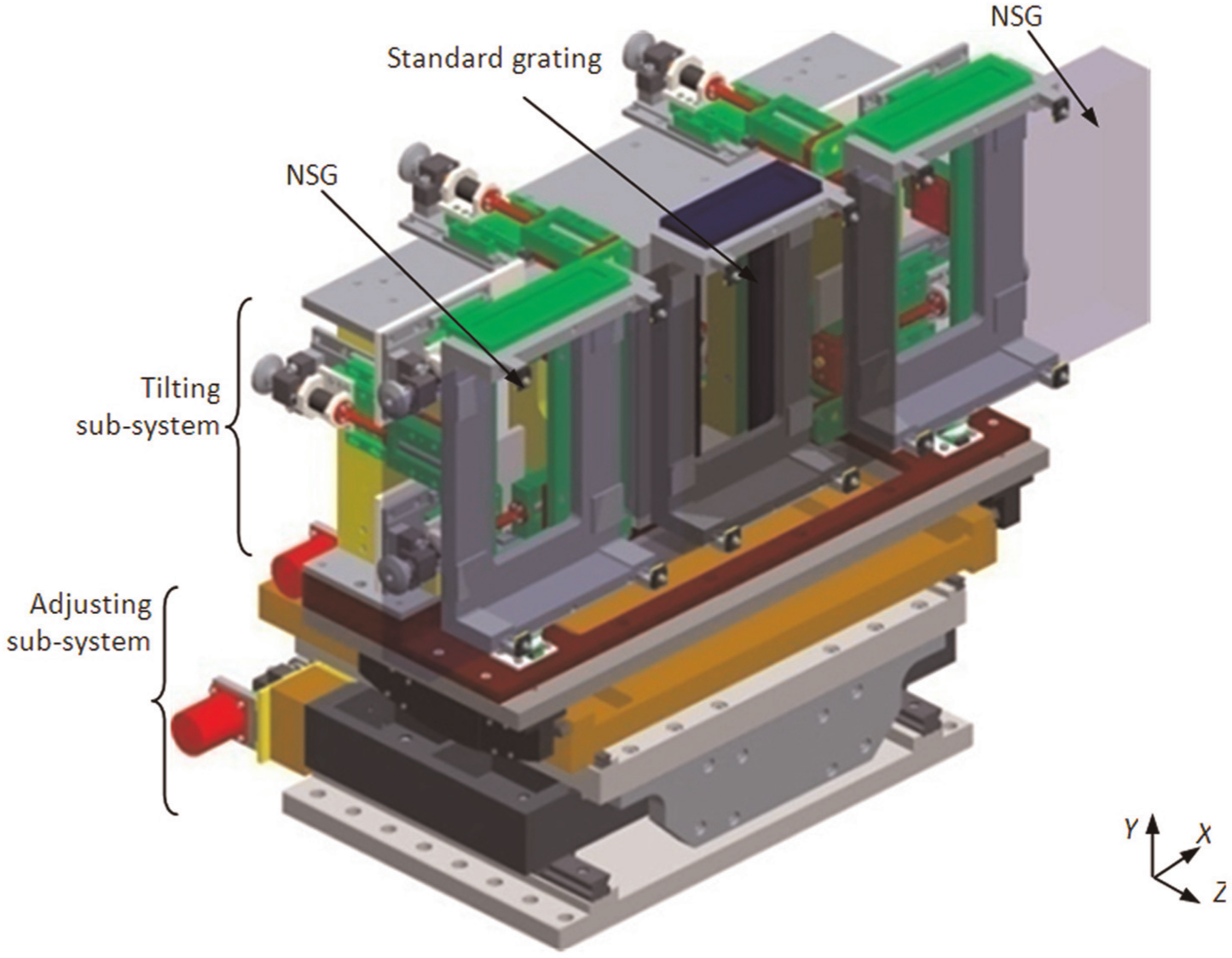
3D model of the large-aperture grating tiling and adjusting device.
Static and modal analyses of the tiling subsystem
Meshed model
Compared with the adjusting subsystem, the accuracy required by the tiling subsystem is much higher. The static and dynamic performances, especially the modal properties in dynamics, play an important role for the final tiling quality, in particular, the tiling precision and stability.
The geometry model of tiling subsystem was imported into the FEA software after necessary simplifications for some details, such as rounds and chamfers, especially for the complex surfaces in modeling. Figure 8 shows the meshed model of the mechanical tiling subsystem. Element type SOLID95 in ANSYS was used for the meshed model. In addition, with regard to the two cross slide and the ball suspensions, element COMBIN14 was also used to simulate the spring effect. The coordinate system, which was described previously, is also shown in Figure 8 to specify the directions in the static and modal analyses results.
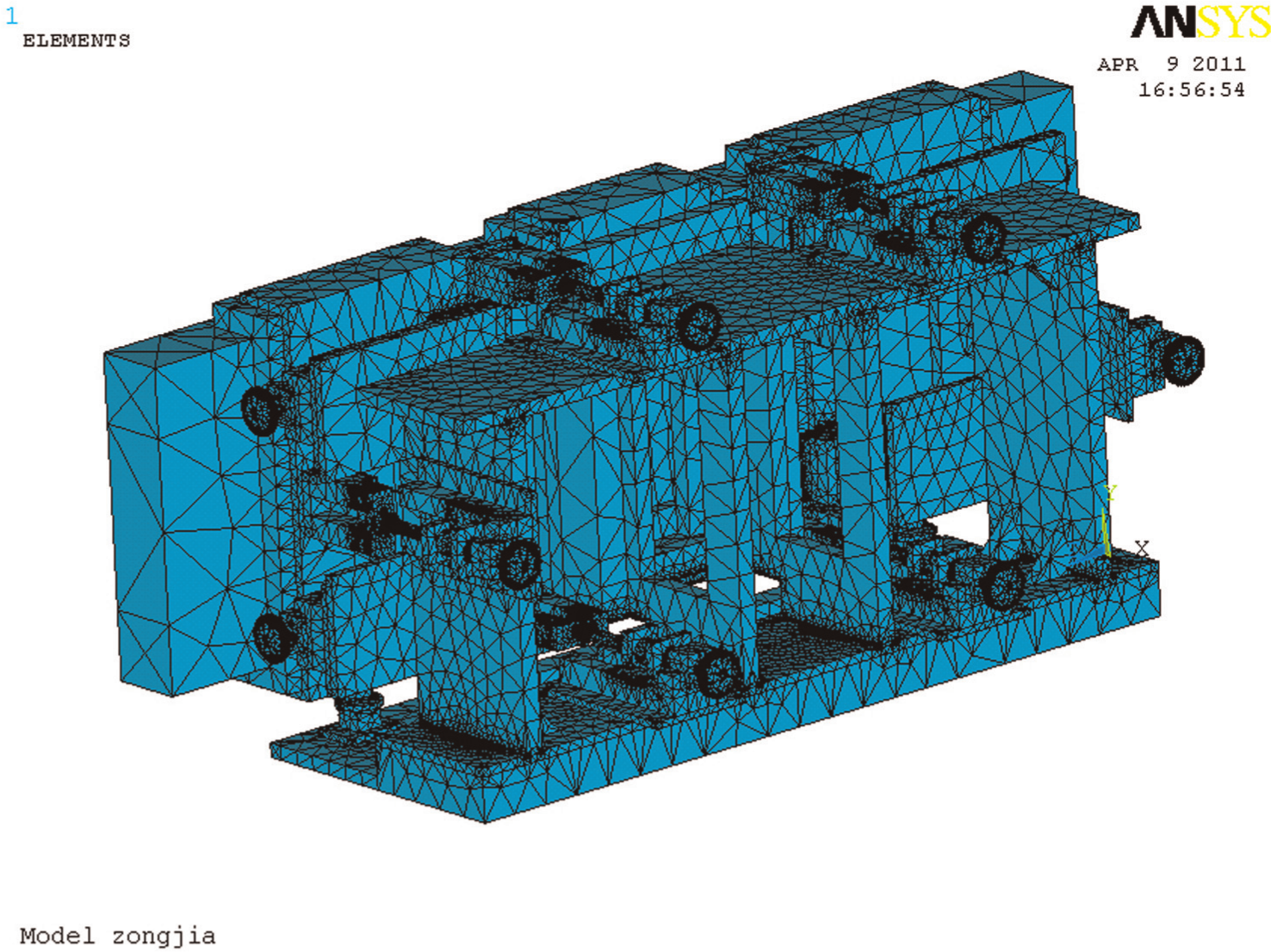
Meshed model of the tiling subsystem.
Static analysis on the tiling subsystem
As the requirement of precision, the static analysis of tiling subsystem focuses on the deformation under the effect of gravity. The constraints for the analysis are simulated according to the actual working conditions, in which the bottom surface of the tiling subsystem was fixed by 16 bolts. Figure 9 shows the static simulation result of the tiling subsystem. It can be calculated from the results that the maximum angle error around X-axis (
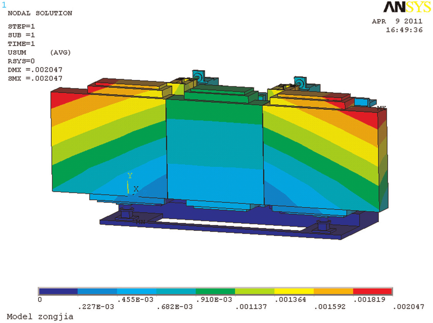
Gravitational analysis of the tiling subsystem.
Modal analysis on the tiling subsystem
The modal analysis results are summarized in Table 1. Under the condition of the first-order inherent frequency, the NSGs could rotate around Z-axis in the same rotational directions for both NSGs and move along X-axis at the same time. According to the requirements of tiled-grating, the rotation around Z-axis had a greater effect on the parallelism of groove patterns on the standard and NSGs but a lesser effect on the intensity of light beam. The linear movement along X-axis of NSG could influence the beam intensity.
15
The second-order inherent frequency was 107 Hz, approximately equal to that of the first order. However, the rotational directions in vibration were reverse for the two NSGs. The effect in the second-order inherent frequency was the same as to that in the first-order inherent frequency. The inherent frequency in the third order was 139 Hz, in which the two NSGs rotate around Z-axis and tilt around X-axis. The effects of rotation around Z-axis (
Vibration mode and frequency of the tiling subsystem.
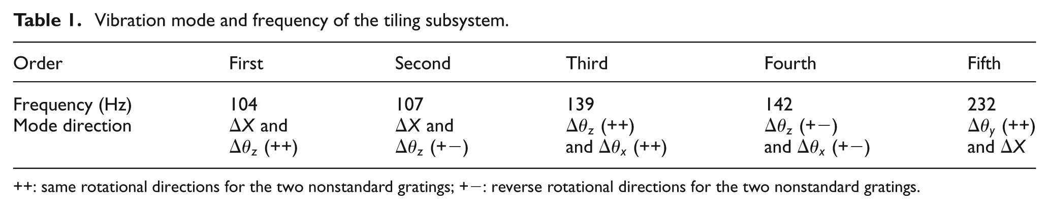
: same rotational directions for the two nonstandard gratings; +−: reverse rotational directions for the two nonstandard gratings.
From the analysis results, the designed mechanical structure for grating tiling has relatively high stiffness and can ensure the accuracy control of tiled-grating system. It can also be found from the analysis that the vibration modes in various vibration frequencies have effects on the accuracy of the tiling target. Since the speed for tiling and adjusting is not the critical parameter required in tiling process, the required accuracy for the driving and positioning can be achieved with the delicate movement in vibration isolation environment.
Testing on the device accuracy, results and discussions
Experimental testing and validation
Generally, to measure the modal properties experimentally is the direct validation on the proposed FE model. However, it is difficult to measure the inherent frequencies and vibration modes of the device equipped with gratings. Accuracy measurement is regarded as an indirect way to validate the simulation results. As demonstrated in Figure 10, the tiling and adjusting subsystems were assembled together and equipped with gratings. In order to check the final performance of the large-aperture grating device, accuracy tests were performed on the developed device. The accuracy tests include linear and rotational movements. The linear movements in the 5 DOFs were tested by using digital length gauge system (HEIDENHAIN CT2500 and ND280), and the three rotational movements were measured by an electronic autocollimator with the accuracy of 0.01 arc-seconds.
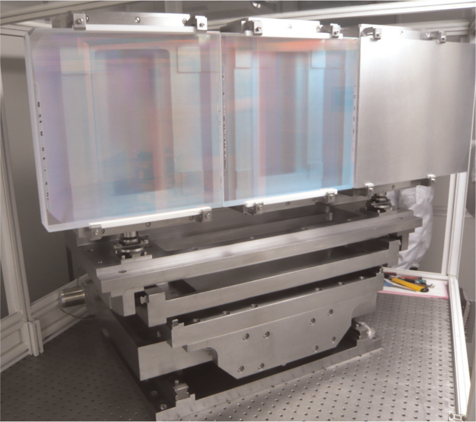
Tiling and adjusting device for gratings (two gratings equipped).
The tiled-gratings were moved according to the programmed centralized control strategy based on our previous research.
14
The controller for the DC motors in the tiling and adjusting subsystems was implemented by programmable multi-axis controller (PMAC)–based control system. In the tiling subsystem, the piezoelectric actuators for the micromovement were controlled by their individual controllers and communicated with the central controller via RS232 serial ports. In the adjusting subsystem, the integral mechanical frame and all parts mounted on it were controlled by centralized computer in serial mechanism. From the statistic data of the testing results, it was found that the step accuracy of 20 nm can be achieved along Z-axis in the tiling subsystem. The rotating results around X-axis and Y-axis in 0.3-µrad step rate are shown in Tables 2 and 3, respectively. The experimental results indicated that the error averages were relatively small. The average relative errors (Er) between input and output in each stoke were below 5%. The accuracy in the rotational movement around Y-axis (
Testing results in the rotational movement around X-axis (
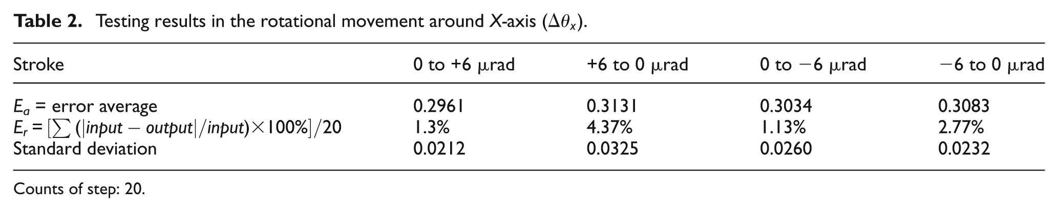
Counts of step: 20.
Testing results in the rotational movement around Y-axis (
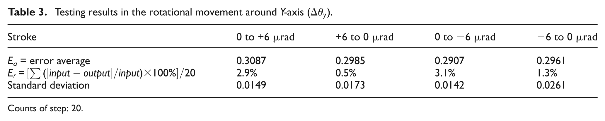
Counts of step: 20.
According to a series of measurement tests, it was proved that the anticipated accuracy of 0.4 µrad in the rotational DOFs of the tiling subsystem could be achieved. The mechanical layout and the part accuracy in machining and assembling contributed to the high rotational accuracy in various DOFs. The testing results also partially validated the high stiffness property of the integral device, as well as the vibration modes from the simulation results. In the test of adjusting subsystem, the average relative errors (Er) between input and output in each stoke were also below 5%.
Movement errors
From the analysis of the testing results, it can be found that the errors for the movement of mechanical device are within the scope of control. The reasons for the movement errors could be laid on the following aspects. The first source of error might come from the manufacturing and assembly errors, especially for the flexure joint and the flexible hinge. For this reason, the ideal geometrical position in the computer controller showed a slight difference from that in the real mechanical tiling subsystem. Second, the driving in control system itself might have inevitable errors within its accuracy scope. Last but not the least, the natural vibration, noise and temperature variation around the experimental environment could also contribute to the error of tiling subsystem output.
The accuracy in the adjusting subsystem was not better than that in the tiling subsystem. The partial reason for the difference was because the driving part in the adjusting system was a step motor with ball screw, whose driving accuracy did not come up to that of piezoelectric actuator in the macro-/microdriver. Furthermore, the connection springs converting from linear motion to rotational motion in the adjusting subsystem also affected the movement accuracy. In order to further increase the accuracy and stability, the mechanism optimization for the adjusting subsystem should be implemented in the future works.
Conclusions
A novel grating tiling and adjusting device has been introduced in this study. The key elements in the mechanical system have been designed and analyzed in detail. The factors related to the error and improving accuracy have also been discussed after the key validation tests for measuring movement accuracy. Based on this study, the following conclusions can be drawn:
The grating tiling and adjusting device designed with integrated, parallel and serial mechanisms was capable for the complex high-power laser facility.
The maximum angles rotating around X-axis (
The tested step accuracy was 20 nm in linear movements and 0.4 µrad in rotational movements of the tiling subsystem, which means that the tiling accuracy could meet the requirements of the laser system.
Footnotes
Appendix 1
Declaration of conflicting interests
The authors declare that there is no conflict of interest.
Funding
This research work was jointly supported by the National Outstanding Young Scholars Foundation of China (grant no. 50925521) and Natural Scientific Research Innovation Foundation in Harbin Institute of Technology (HIT NSRIF 2009012).