
Abstract
A tensile testing device is a crucial device for the assessment of mechanics behavior of micro structures. This article presents a tensile testing device based on a piezoelectric actuator. The mechanical structures of the device, including flexible hinge and flexure driving connector, are designed and analyzed by using a finite element method. After careful analysis and determination for the key structural parameters, the tensile device was set up and tested so as to obtain the desired accuracy. Tensile tests on copper micro wires with φ50 µm diameter were conducted, and stress–strain curves and tensile patterns of the wires have been presented by using the device developed. It is shown that the resolution for tensile movement can be 10 nm, with the scattering position accuracy of ±0.01 µm in a stroke of 37.1 µm. The results from both simulation and experiments reveal that the tensile testing device developed is effective and reliable, and meets the design specifications.
Keywords
Introduction
Low-dimensional structures, such as microgirder, microrod, or even microwire, are usually used in micro-electromechanical systems (MEMSs). With the development of MEMS devices, the tests for their mechanical properties, in traditional experimental set-up and conditions, cannot meet the design requirements of mechanical structure of MEMSs. Though some mechanics parameters can be obtained by some computer simulation methods, such as molecular dynamics (MD) or finite element method (FEM), the results are hard to be verified through experiments. Actually, testing experiments can offer a viable way to evaluate the mechanics behavior of micro structures. Therefore, development of a testing device for micro structures can bring benefit to the design and function realization of micro structures and its mechanics assessment, which will also contribute to set up the design criterion of micro structures.
Among all the testing methods for mechanics parameters of micro structures, tensile experiment can be an effective and ideal approach for the measurement of yield strength, tensile strength and elastic module of a micro structure.1,2 However, traditional tensile testing devices cannot be used for testing micro structures because of the requirements for high movement accuracy and a critical installation condition in micro tensile testing. The tensile testing for micro structures has imposed the challenge to the development of the tensile testing device.
Over time, many attempts for the test of micro structures have been made to investigate the tensile behavior for meeting the requirement of MEMS parts. Read 3 developed micro tensile test apparatus, in which a piezo-actuator was used and an elastic beam acted as the force sensor. Zhu et al. 4 designed a tensile device with an achievable displacement resolution of 3 nm. However, the test experiment conditions were extremely strict to some extent, which was not convenient for the manipulating process of the tested specimen. Some available experimental devices have been developed to investigate the mechanics behavior by using scanning electron microscopy (SEM), atomic force microscopy (AFM) or transmission electron microscopy (TEM).5–7 These devices contributed greatly to the development of mechanical property tests in micro/nano scale, with which the size-dependent effects could be analyzed by tensile experiments even in nanoscale. However, these devices were either much more complicated in their mechanisms or operation, or not suitable for the test of micro wires.
In this article, a novel tensile testing device is presented for mechanical micro structures. The background and state-of-the-art research are critically reviewed first. The design and analysis of the device are then described in ‘Structure design of the micro tensile testing device’, with the testing experiments on using the device in ‘Tensile testing experiments and validation’. Conclusions are then drawn in light of the device development and testing experiments.
Structure design of the micro tensile testing device
Layout of the mechanical system
The designed tensile system includes three sub-systems, i.e. mechanical tensile sub-system, imagining sub-system and measuring sub-system. Among all the sub-systems, the mechanical tensile sub-system is the dominant part, which involves driving assembly and tensile assembly. Figure 1 shows the two-dimensional (2D) layout of the mechanical tensile sub-system. In the driving assembly (dashed area in Figure 1) of the mechanical tensile sub-system, the piezoelectric actuator acts as the main driving element, which combines with flexible hinge, flexure driving connector, ball and other mechanical parts (9, 10, 11 and 13 in Figure 1). The tensile assembly includes base board, support board, movement bench, specimen plate, static bench and three-dimensional (3D) stage. The digital microscope and computer data processing system compose the imagining sub-system. Digital length gauge and force sensor are the key elements for the measuring sub-system.
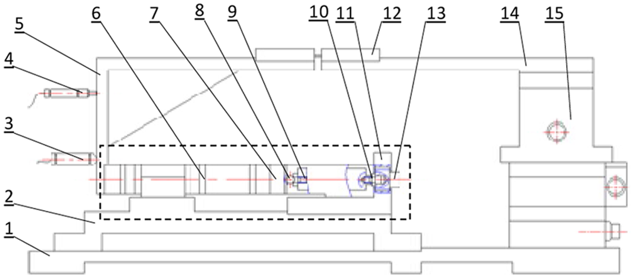
The layout of tensile device. 1: base board; 2: support board; 3: digital length gauge; 4: force sensor; 5: movement bench; 6: flexure driving connector; 7: flexible hinge; 8: ball; 9: piezoelectric actuator; 10: PZT connector; 11: L-plate; 12: specimen plate; 13: screw; 14: static bench; 15: 3D stage.
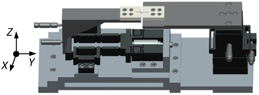
The compact 3D mechanical model is shown in Figure 2. The output displacement of the close-loop piezoelectric actuator, whose nominal stoke is 40 µm, can be controlled by either an adjustable knob on the panel of power supply or the outside analog signal. A 3D miniaturized movement stage (15 in Figure 1) is utilized in the tensile sub-system. With the stokes of 25 mm in the X and Y directions and 5 mm in the Z direction, the high-precision stage can perform for the pre-installation and positioning of the specimen to be tested. In the imagining sub-system, a digital microscope (Magnification: 500×) is mounted and communicates with the computer via a universal serial bus (USB). The tensile system is also equipped with displacement and force sensors for measuring tensile displacement and force.
3D model of the tensile testing device.
Design and analysis of key mechanical parts on the device
Flexible hinge for the piezoelectric actuator
The flexible hinge for the piezoelectric actuator is designed with a symmetrical structure, which can eliminate the coupled errors and increase the capability of anti-disturbance. With a compact design, the flexible hinge for the piezoelectric actuator can be used for the tightening piezoelectric actuator with one screw (13 in Figure 1). The stiffness for the flexible hinge can have great effects on the performance of the driving assembly. The smaller the stiffness of the flexible hinge for the piezoelectric actuator, the lower its inherent frequency, which can lead to a lower response speed and worse capability of anti-disturbance for the driving assembly. On the other hand, a larger stiffness of the flexible hinge for the piezoelectric actuator can cause a smaller output displacement of the driving assembly, and might not reach the anticipant output results. So, in the design process of the flexible hinge, the stiffness can be much higher than possible under the condition of the output displacement required.
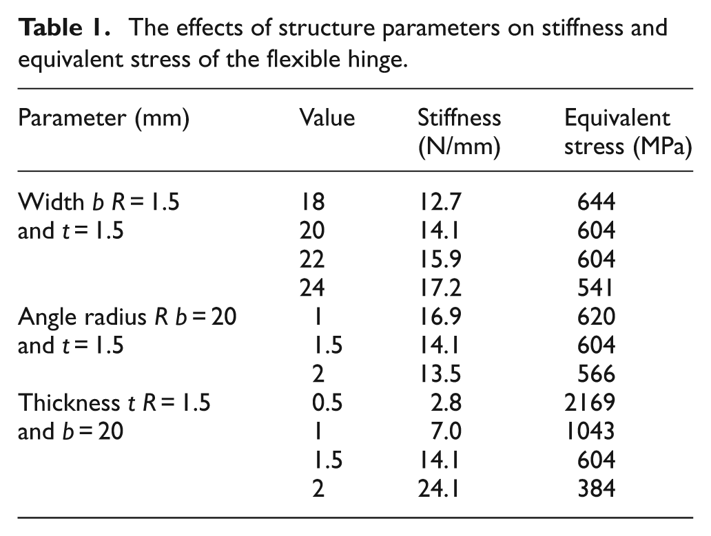
Figure 3 shows the sketch of the designed flexible hinge. Among all the structural parameters of the flexible hinge, the thickness t (four positions in Figure 3), angle radius R (eight positions in Figure 3) and the width b, are more important than others for its working performance. Table 1 lists the effects of structure parameters on stiffness and equivalent stress (maximum von Mises stress) of the flexible hinge under the given loading. It can be shown that the effects of the three parameters on stiffness and equivalent stress are various. The thickness t may show more effects on the stiffness, while it’s changing from 0.5 mm to 2 mm. Moreover, the stiffness doesn’t change dramatically while the width b changes from 18 mm to 24 mm.
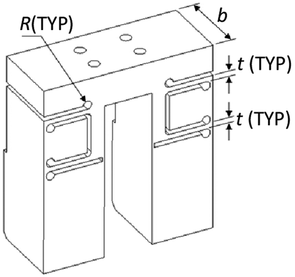
Sketch of the flexible hinge.
The effects of structure parameters on stiffness and equivalent stress of the flexible hinge.
According to the effect analysis of key structural parameters on the stiffness and equivalent stress of the flexible hinge, the thickness, angle radius and width of the flexible hinge are determined as t = 1.8 mm, R = 1.5 mm and b = 20 mm. The determined parameters are also considered under the proper space requirements in the design.
With the determined parameters and finite element analysis (FEA) simulation, the displacement and equivalent stress of the flexible hinge under the effect of 880 N force in the Z-axis direction are shown in Figures 4 and 5. From the analysis results, it is shown that the maximum von Mises stress is 181 MPa and the maximum displacement is 44 µm. So the calculated stiffness of the flexible hinge is 20 N/µm under this condition. It is also shown that the stress concentration, visible in Figure 5, occurred in the weak corner of the flexible hinge. However, the maximum equivalent stress is far smaller than the flexible hinge material’s allowable stress. According to the analysis, it is indicated that the design of the flexible hinge for the piezoelectric actuator can meet the requirements of the micro tensile device.
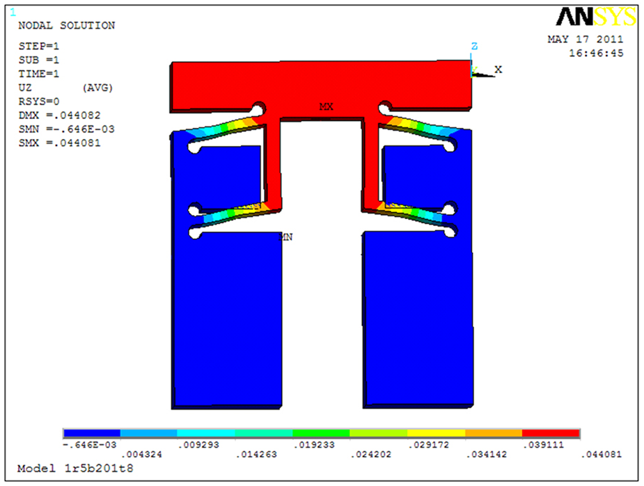
Displacement contour of the flexible hinge.
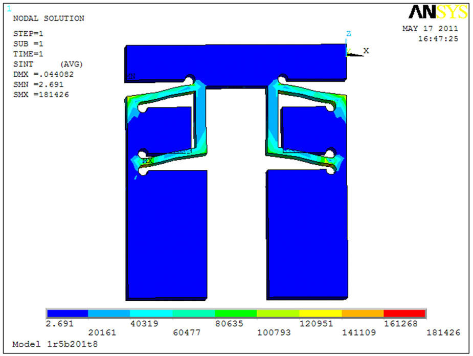
Equivalent stress contour of the flexible hinge.
Flexure driving connector
The function of flexure driving connector is to magnify the displacement from the piezoelectric actuator and to guide it for tensile movement. The magnification of the flexure driving connector is evaluated carefully from the results of FEA. It is shown that the output displacements of flexure driving connector are 15.184 µm, 30.383 µm and 45.551 µm, when 10 µm, 20 µm and 30 µm displacements are exerted separately on the flexible hinge’s input end. From the analysis results, the magnification factor can be about ×1.5.
Theoretically, the magnification factor can reach ×2. The reason for this differentia is because the elastic deformation of various sub-joints in the mechanical driving mechanisms. As the actual stiffness is lower than that in the simulation, the actual magnification factor in a real tensile process can be smaller than ×1.5. In addition, the actual output displacement can be smaller than that in simulation for the reason of connection and mechanical counteractive force from the flexible hinge. However, the results from simulation can provide valuable reference for estimating the effectivity of the mechanical driving mechanism. Figures 6 and 7 show the displacement and equivalent stress contours of the mechanical driving mechanisms (the flexible hinge and the flexure driving connector), respectively. The stiffness in the analyzed driving mechanical mechanisms is 36.5 N/µm and the maximum equivalent stress is 211 MPa under the determined parameters.
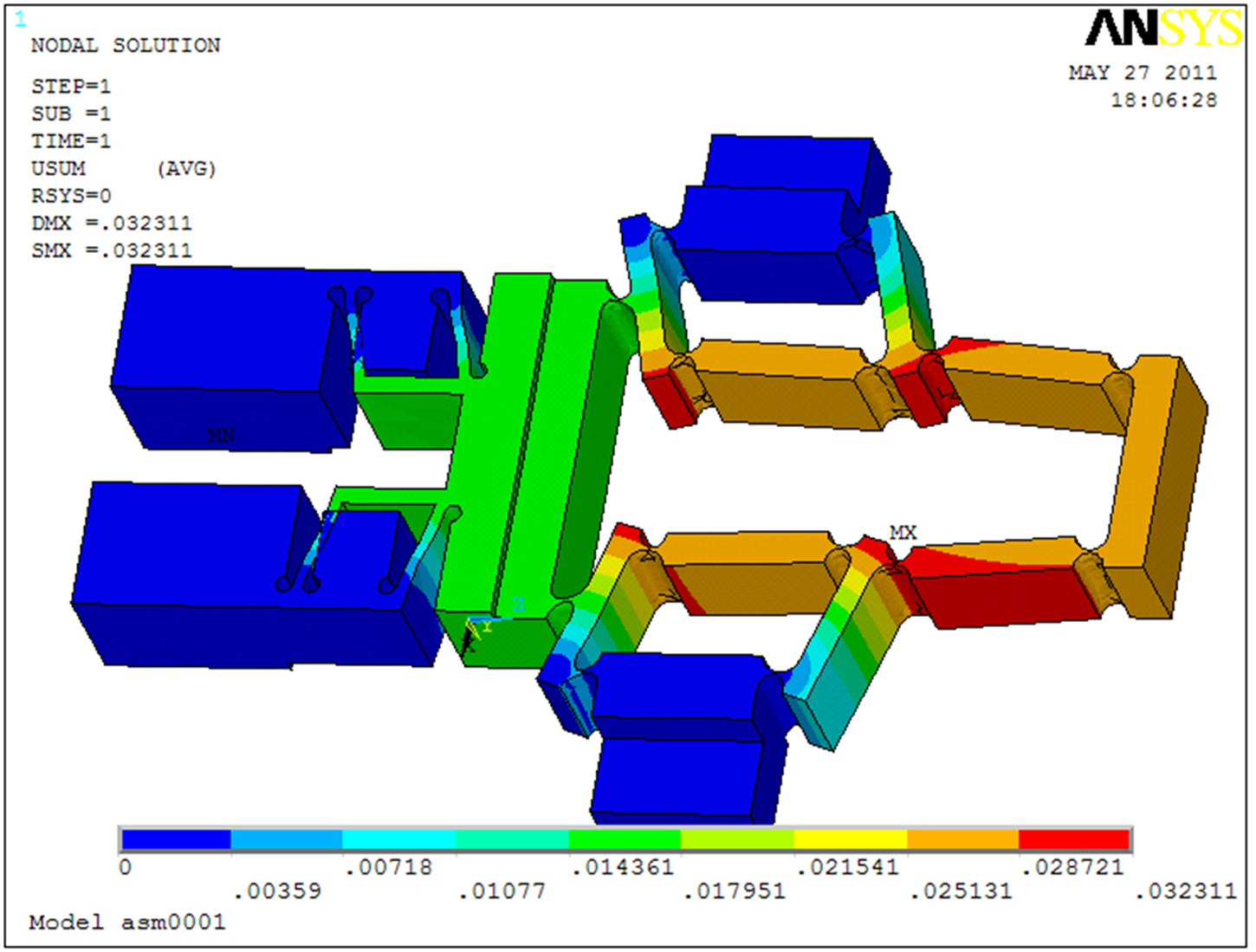
Displacement contour of the mechanical driving mechanisms.
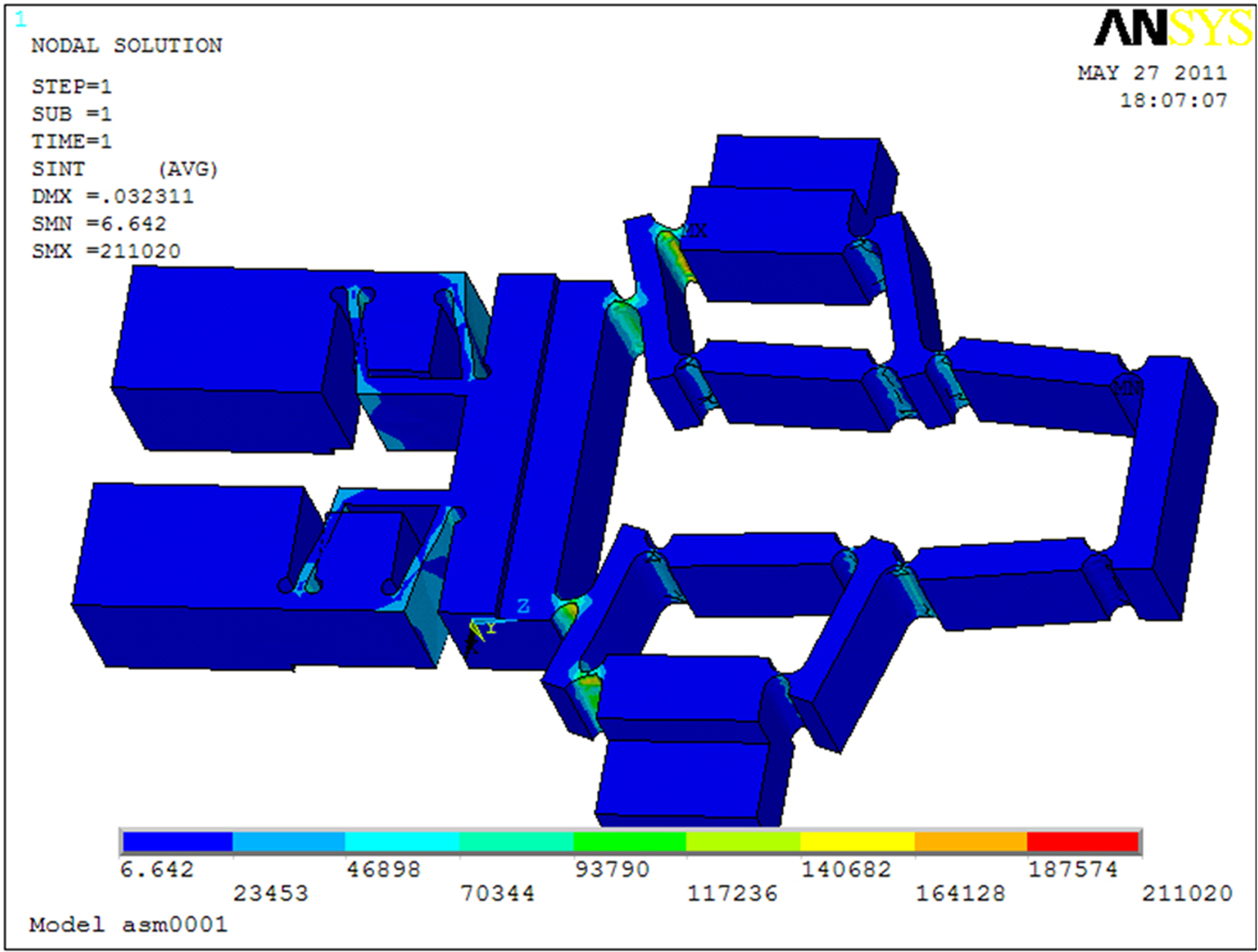
Equivalent stress contour of the mechanical driving mechanisms.
Device system setup and accuracy analysis
Figure 8 presents the developed tensile device system set-up with its mechanical tensile sub-system and imagining sub-system. The scatter positioning accuracy is measured and analyzed. When 20 µm input displacement is applied on the piezoelectric actuator, the output of the pre-tightened mechanism will show 15.2 µm through measurement. Moreover, the output displacement may decrease with an increase in the pre-tightened force on the flexible hinge. The actual output displacement ΔL can be expressed as

where ΔL0 is the nominal output displacement from the piezoelectric actuator without outside loading, Kp is the stiffness of the piezoelectric actuator and Ks is the stiffness of the flexible hinge. The nominal output stiffness Kp is 60 N/µm from the piezoelectric actuator specification. According to the analysis of ‘Design and analysis of key mechanical parts on the device’, the stiffness (Ks) is 20 N/µm. So given that ΔL0 is equal to 20 µm, the actual output displacement ΔL is 15 µm, which is in good accordance with the experimental results. Moreover, from equation (1), it can also be deduced that the output displacement will decrease while increasing the stiffness (Ks) of the flexible hinge.
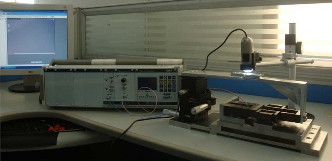
Photograph of the micro wire tensile device.
According to a series of experiments, the resolution for micro displacement in the tensile device can be measured as 10 nm. The standard deviations of repeatable positioning for five different positions are measured and calculated as σ1 = ±0.008 µm, σ2 = ±0.006 µm, σ3 = ±0.01 µm, σ4 = ±0.01 µm and σ5 = ±0.009 µm. So the scattering positioning accuracy can be drawn from equation (2). The scattering positioning accuracy is ±0.01 µm in the measuring range of 37.1 µm

Tensile testing experiments and validation
Copper micro wires with a diameter of 50 φµm are used as the specimen for testing the performance of the tensile device developed. With the measurement of tensile force, displacement and section area, the stress–strain data can be obtained after the experiments on the tensile device. Figure 9 shows the experimental stress–strain curve of copper micro wires, tested on the tensile device. It can be indicated from the curve that the yield strength is 86.5 MPa, tensile strength is 114.4 MPa and the longitudinal stretch ratio is 0.4.
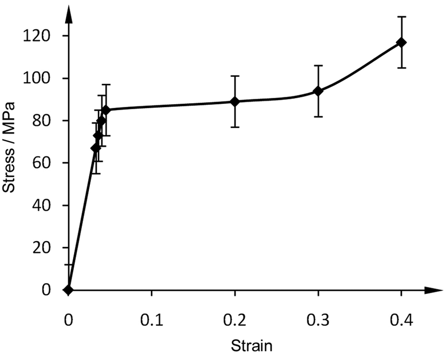
Tensile curve of the copper micro wire.
Two kinds of micro wire specimen were explored in the tensile test while validating the device designed. One is integral copper micro wire, as used previously for measuring mechanics parameters, and the other is copper micro wire with a small V-shape cut (5 µm × 5 µm). Figure 10 shows the time-dependant pattern of tensile copper micro wires. The first column is the geometric model of micro wires. The pictures in other columns are captured from the imagining sub-system with 500× magnification. The pictures in the first row show the tensile process of the integral copper micro wire. It can be observed that the shape deformation, though not quite prominent on the specimen with the V-shape cut, will occur initially. Then the copper micro wire will be pulled out till no plastic deformation can be produced. Compared with the integrated micro wire, the specimen with the V-shape cut is more liable tensile failure as expected. The maximum tensile displacement is 16 µm for the copper micro wire with V-shape cut to be broken up. Whereas, it need about 32 µm tensile displacement for the integral micro wire.
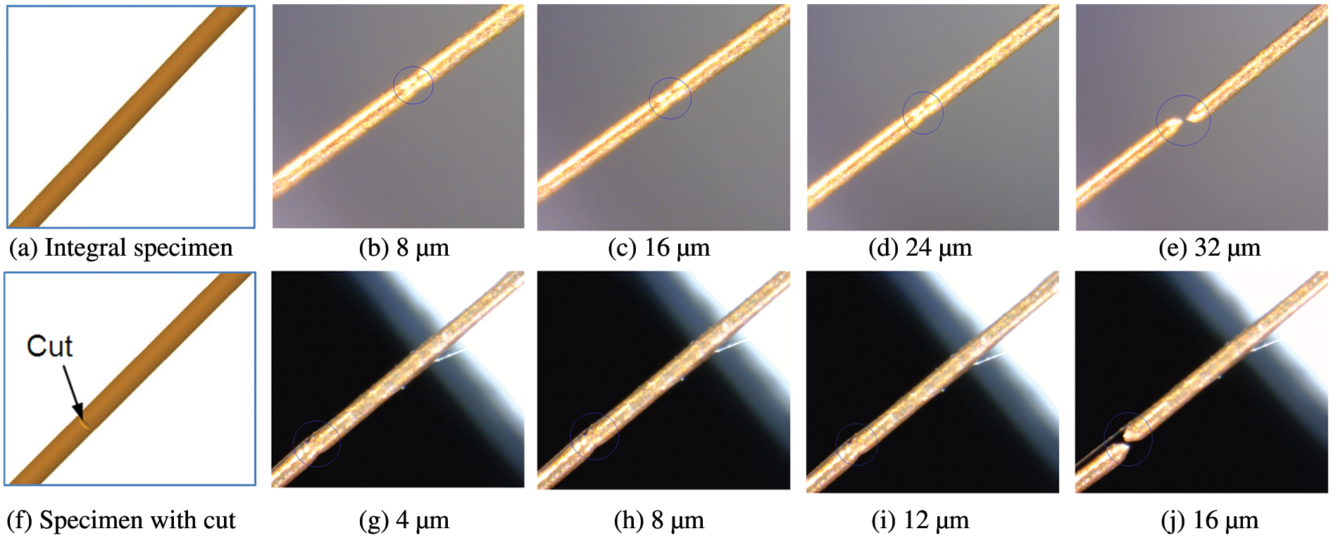
Tensile pattern of the copper micro wires with and without cut (500×).
The stress concentration in the V-shape cut can lead to the quick failure of the tensile process of copper micro wires. The abrupt fracture can be more easily found in the tensile process of the cut specimen. The micro cut on the specimen may contribute greatly to the abrupt fracture mechanism of copper micro wires. To sum up, the testing device developed and tensile experiments offer the function realization and effective validation for the tensile process of micro wires.
Conclusions
Based on the piezoelectric driving technique and FEM-based design, a novel tensile device for micro wire is developed. The mechanical properties of the key parts are analyzed and the tensile experiments are carried out on the designed device. The following conclusions can be drawn.
In the three parameters investigated, the thickness t was found to be the most significant factor and the width b to be the smallest effects on the stiffness of the flexible hinge in the designed tensile device.
The resolution for tensile movement is 10 nm and the scattering position accuracy is ±0.01 µm in stoke of 37.1 µm.
The test results from the designed device shows that yield strength is 86.5 MPa, tensile strength is 114.4 MPa and the longitudinal stretch ratio is 0.4 for the copper micro wire.
The tensile patterns for two kinds of specimen in various displacements are presented, which show that the developed device is effective and reliable.
Footnotes
Funding
This research is supported by the National Outstanding Young Scholars Foundation of China [Grant No. 50925521] and the Natural Scientific Research Innovation Foundation in Harbin Institute of Technology [HIT. NSRIF. 2009012].