
Abstract
Injection forging allows producing near-net or net-shape asymmetric branched components with geometries that are difficult or impossible to fabricate by means of conventional impression die forging. On the contrary to previous research work in the field that was mainly focused on proposing methodologies for shape classification, systematization of forming defects, definition of workability ranges and evaluation of the overall performance of finite element predictions against experiments, the aims and scope of this article are centred in material flow and forging load requirements that result from double-acting tool concepts with closing spring elements. The presentation includes details on the active tool parts that were utilized for producing solid branched components with different numbers of radial straight legs, on the mechanical characterization of the material and on the numerical simulation and experiments that were performed with selected test cases. Results and observations confirm that double-acting tool concept with closing spring elements is a flexible and efficient manufacturing process for producing injection forged components because it can eliminate the formability problems and defects that are commonly found in single-acting tool concepts and can avoid the need for employing multi-acting presses with counteracting punches.
Introduction
Trends in the production of complicated forged parts, with narrower tolerances, over the past decades are leading to the progressive replacement of conventional impression die forging by near-net and net-shape forging processes, where no subsequent machining or finishing of the forged parts is required.
Because near-net or net-shape forged parts are high precision components with complex functional surfaces that are produced to final tolerances, their project and design are difficult and influenced by numerous operating parameters. Therefore, besides the need to employ numerical simulation tools based on the finite element method to determine how material properties, tribological conditions, machine tool specifications and forging operating parameters interact with each other and affect the quality of the required forged part, it is absolutely necessary to have a good understanding of the deformation mechanics of the near-net or net-shape forging in closed dies. State-of-the-art finite element computer programs and procedures must be complemented with fundamental knowledge on design and kinematics of tooling systems in order to eliminate conceptual ideas that may lead to inappropriate material flow, difficulties in die filling or unnecessary extra load from further consideration in the very early stages of process development.
Injection forging (also known as ‘side’ or ‘lateral’ extrusion) is a near-net or net-shape forging process commonly utilized for producing axisymmetric flanges on solid rods or tubes, which requires adequate knowledge on tooling systems. The process is characterized by the axial movement of one or two opposed punches (single- or double-acting tool concepts) inside an injection die chamber that leads to localized radial displacement of the work material into a die cavity opening or just into an annular space to form the required component (Figure 1).
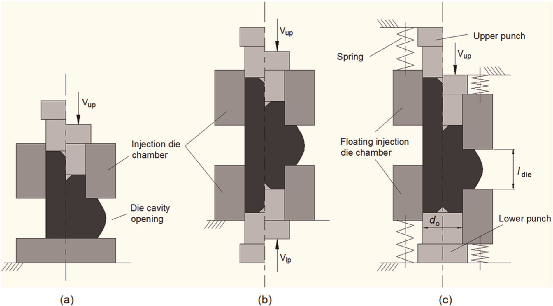
Schematic representation of (a) the single-acting injection forging process, (b) the double-acting injection forging process with two counteracting punches and (c) the double-acting injection forging process with a single-acting punch and a movable floating die driven by spring elements.
Pioneering investigations in the injection forging of axisymmetric flanges from solid rods were carried out in the 1970s1,2 but the most comprehensive studies in the field were only performed in the 1980s and 1990s by Balendra and Qin3,4 who analysed the deformation mechanics, established the process formability limits and identified and classified the typical flow-dependent defects. In what concerns injection forging of axisymmetric tubular flanges, pioneering investigations date back to the mid-1970s5,6 but the process and its variants were only comprehensively systematized in the 1990s. A review of the research in the field was presented by Arentoft et al. 7 in 1995, and the first application of net-shape injection forging of an industrial tubular component was given, as far as the authors are aware, by Colla et al. 8 who also introduced the concept of two-stage injection forging.
The research in injection forging of asymmetric components, in which the solid rods or tubes are radially extruded in several directions to produce solid or hollow branched components, started in the 1990s. Work in the field has been driven by the above-mentioned trend of replacing conventional impression die forging by near-net or net-shape forging processes that, in most cases, are to be performed in a single operation. Spiders for universal joints, alternator pole parts with claws and joining elements for tube and frame connection systems are examples of near-net or net-shape industrial components that are difficult or impossible to fabricate by conventional impression die forging but can be successfully produced by injection forging. Balendra and Qin9,10 presented reviews of the state of the art in injection forging of asymmetric components in the late 1990s and mid-2000s and also proposed methodologies for the classification of asymmetric shapes, the systematization of forming defects and the definition of workability ranges.
Jun et al. 11 were among the first researchers to perform three-dimensional modelling of solid branched injection forged components and concluded on the feasibility of the finite element flow formulation to predict shapes in good agreement with experiments carried out in components with one and two radial straight legs. Çan et al. 12 presented an upper bound solution for the injection forging of spline and spur gears that allows determining the punch pressure and the forging load with respect to several process parameters. More recently, it is worth mentioning the experimental and numerical investigation of the injection forging of splines performed by Zadshakoyan et al. 13 and the new developments in the injection forging of asymmetric tubular components that were proposed by Rudolf. 14
This article is focused on the production of asymmetric branched components by injection forging of solid rods, and its contribution to knowledge is not the development of a new forging process, as can be easily concluded from the state-of-the-art in the field, but the identification of a new level of understanding for the injection forging of asymmetric solid branched components produced in double-acting tools with closing spring elements. Aims and scope include a new level of insight into the influence of the number of radial straight legs in material flow and forging load requirements and on the influence of the kinematics of the movable active tool components in the final geometry of the injection forged components. The overall methodology is based on independently determined mechanical properties of the work material, experimentation with laboratory tooling set-ups and process modelling by finite elements.
Experimentation
Mechanical and frictional characterization
The work material utilized in the investigation was technically pure lead (99.9%). Technically pure lead was chosen because it is commonly utilized in physical modelling of bulk metal forming processes due to its near-ideal rigid-plastic mechanical behaviour that is frequently assumed by classical analytical modelling of material flow in the absence of strain hardening. In addition, the choice of technically pure lead also allows analysing material flow of conventional engineering materials at warm and hot temperatures by means of experimentation at room temperature with low strain rates. 15
The stress–strain response of technically pure lead was determined by upset compression tests at room temperature on cylindrical specimens with equal height and diameter (20 mm). Teflon lubricating foils placed in-between the specimens and the upper and lower compression platens ensured homogeneous deformation. The tests were carried out on an INSTRON SATEC hydraulic testing machine with a cross-head velocity equal to 100 mm/min (1.7 mm/s) under an average strain rate of 0.09 s−1, and the stress–strain curve, in accordance with Hollomon’s equation, is given as follows (Figure 2)

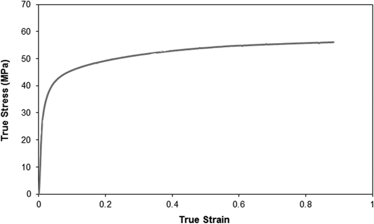
Stress–strain curve of technically pure lead obtained from compression tests at room temperature.
The frictional conditions at the contact interface between technically pure lead and tooling were characterized by means of the ring compression test. The ring test specimens were prepared in accordance with the lubrication procedure utilized in injection forging (zinc stearate), and friction was specified in terms of the constant friction factor
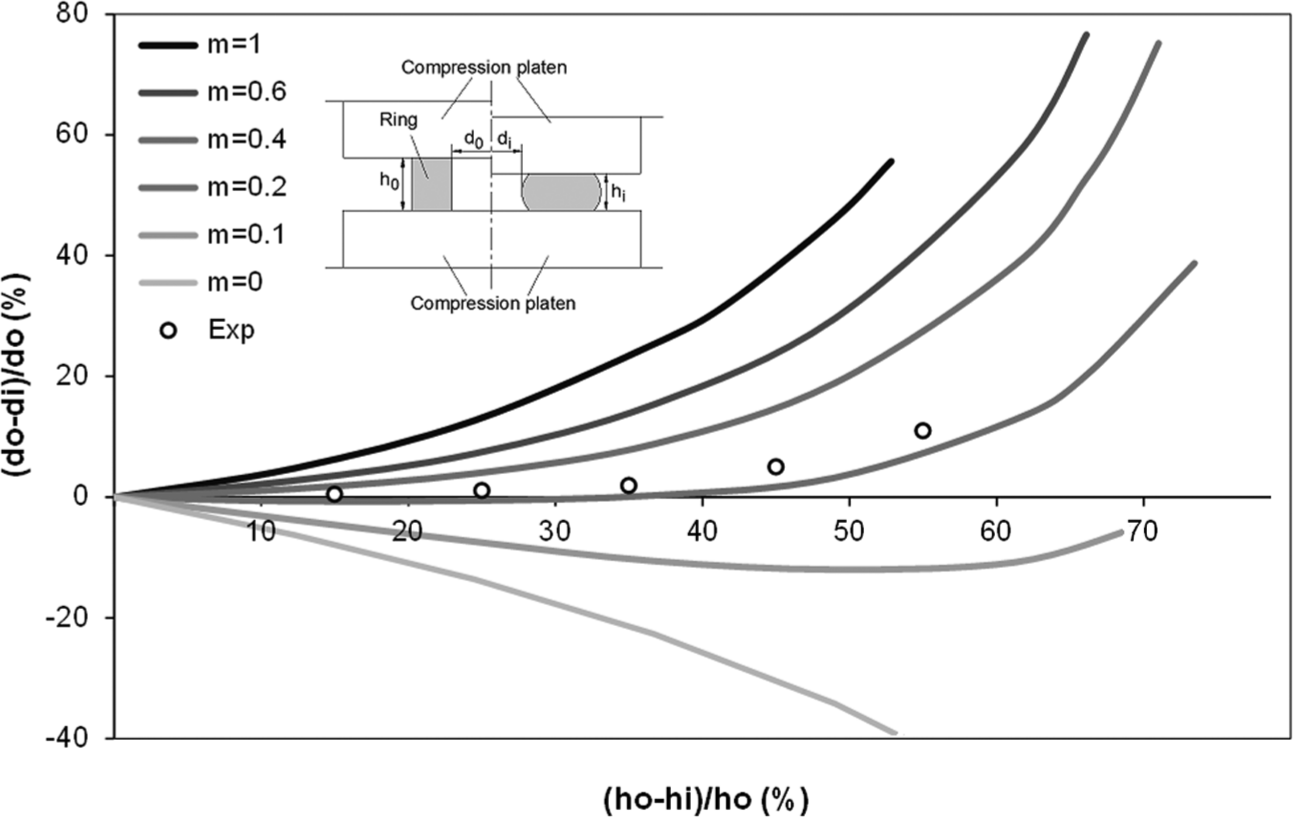
Experimental results and friction calibration curves for the ring compression test.
Methodology and work plan
The investigation on material flow and forming load requirements in asymmetric injection forging made use of a double-acting tool concept equipped with a movable floating die and closing spring elements. Four different experimental set-ups were utilized; three apparatuses for producing solid branched components with (a) one, (b) two and (c) four radial straight legs and (d) one apparatus for producing axisymmetric radial flanges, which were taken as reference test cases for comparison purposes (refer to Figure 4(a)–(d)).
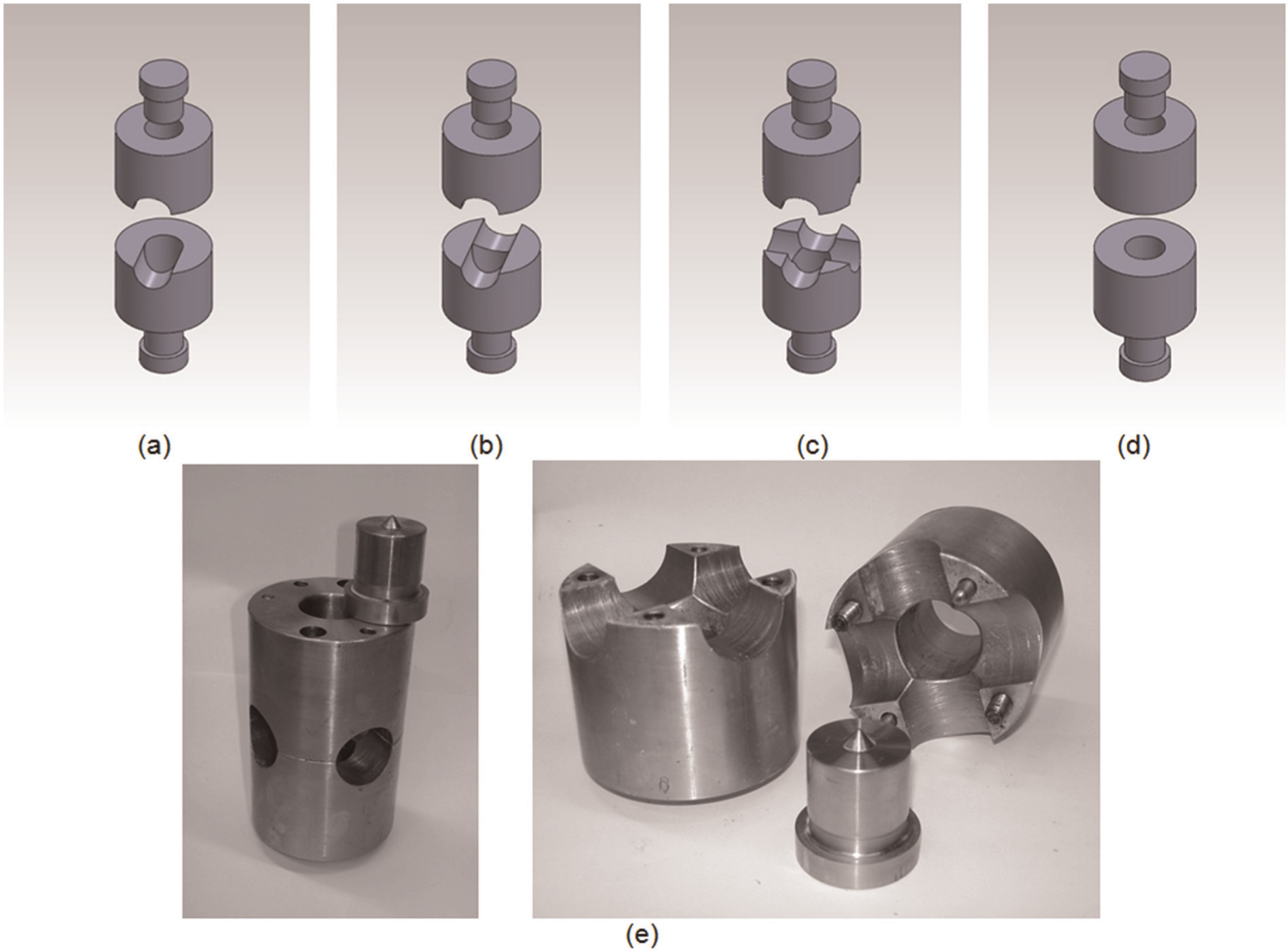
Schematic representation of the active tool components of the experimental apparatuses that were utilized for producing asymmetric branched components with (a) one, (b) two and (c) four radial straight legs (refer also to the (e) photograph) and (d) reference axisymmetric flanges.
Figure 4(e) shows a picture of the active tool components (horizontally divide floating dies and punches) and these were utilized for producing solid branched components with four radial straight legs. The dies are designed to a particular reference diameter
The experiments were performed in a double-acting injection forging tool system equipped with a floating die that moves against the lower stationary punch by means of spring elements that are compressed by the ram and the injection die chamber. Figure 1(c) shows the initial and final stages of the injection forging process. As seen, forging is performed by compressing one specimen end towards the other inside the injection die chamber while progressively forcing the material into the die cavities in order to obtain the required radial straight legs. The investigation on the influence of the relative velocity between the movable punch and floating die in the final geometry of the injection forged components was performed by carrying out experiments with two different types of the spring closing elements having spring constants
The experimental apparatuses that are schematically depicted in Figure 4 were installed in a INSTRON SATEC static hydraulic universal testing machine with 1200 kN capacity, and the tests were performed with a constant displacement rate of the upper-table equal to 100 mm/min (1.7 mm/s). The specimens utilized in the investigation consisted of solid rods of technically pure lead with a diameter of 32 mm and initial length of 110 mm. Before being inserted into the floating injection die chamber, the specimens were lubricated with zinc stearate. By keeping the ratio of the die cavity opening to the reference diameter of the specimens
Plan of experiments.
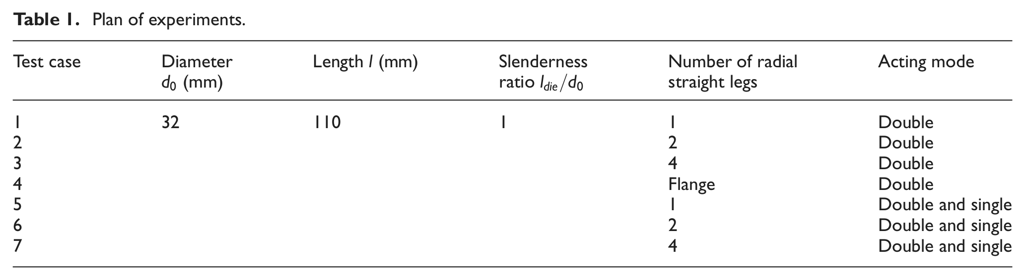
Because the experiments were carried out at room temperature with a very small cross-head velocity, no inertial effects were found and, therefore, no dynamic contributions to plastic flow were taken into consideration. Such testing conditions permitted injection forging of asymmetric and axisymmetric solid branched components to be modelled with the finite element flow formulation that will be briefly described in the next section.
Finite element modelling
Finite element modelling of the injection forging process made use of the in-house computer program I-form, which is based on the irreducible flow formulation.
16
The variational principle that gives support to this formulation requires that among all the admissible velocities
where
In the present investigation, friction was modelled with the law of constant friction
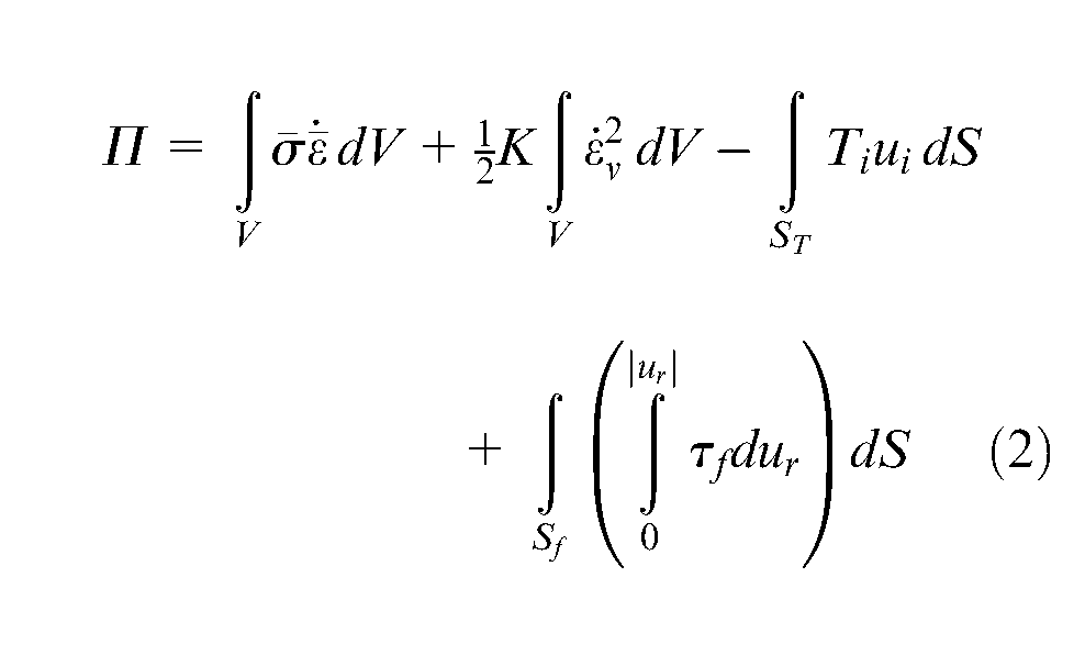
The work material was discretized into hexahedral elements, and the volume integrals in equation (2) were evaluated by means of complete and reduced integration schemes in order to ensure incompressibility of the plastic flow. The rightmost boundary integral in equation (2) required dies and punches to be discretized by means of contact–friction spatial triangles and made use of a five-Gauss point integration rule (Figure 5(a)).16,17
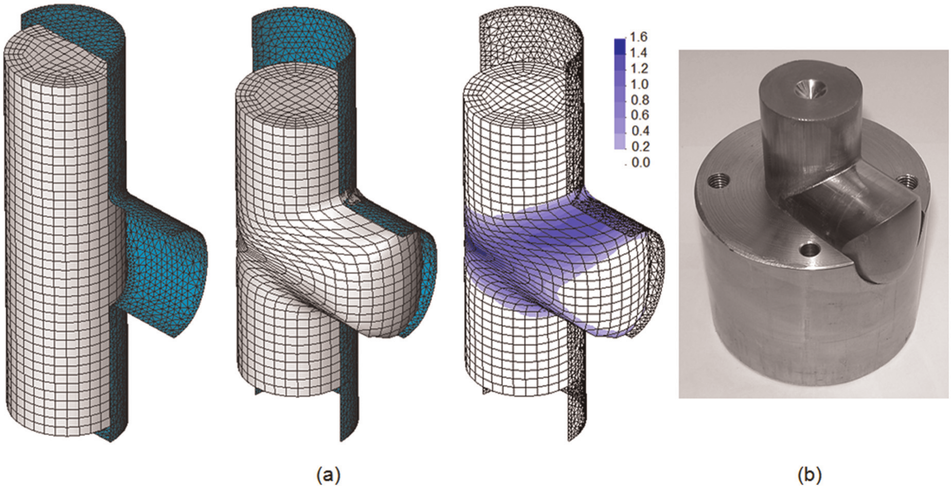
Finite element model utilized in the numerical simulation of asymmetric solid branched components with one radial straight leg: (a) Discretization of the preform and tooling by means of hexahedral and spatial triangular finite elements, respectively, computed predicted geometry and distribution of effective strain at the end of stroke. (b) Photograph of the component and lower die corresponding to modelling conditions in (a).
Different finite element models were set-up in order to replicate the asymmetric and axisymmetric experimental test cases of Table 1. Figure 5, for example, shows a test case taken from the injection forging of an asymmetric solid branched component with one radial straight leg (case 1 of Table 1). The agreement between experimental and computed predicted geometry at the end of stroke is very good.
The numerical simulations of the experimental test cases were performed through a succession of displacement increments each of one modelling approximately 0.1% of the initial specimen length. No remeshing operations were performed, and the overall computing time for a typical analysis containing 8000 elements and 10,000 nodal points was below 30 min on a standard laptop computer equipped with an Intel i7 CPU (2.7 GHz) processor and making use of four cores.
Results and discussion
Modes of deformation
The first set of experiments (cases 1–4 in Table 1) was carried out in double-acting injection forging mode where the upper punch moved downwards with a constant velocity
As shown in Figure 6, the experimental and finite element predicted geometries of the components agree well at the end of stroke, and the distribution of the normalized total velocity
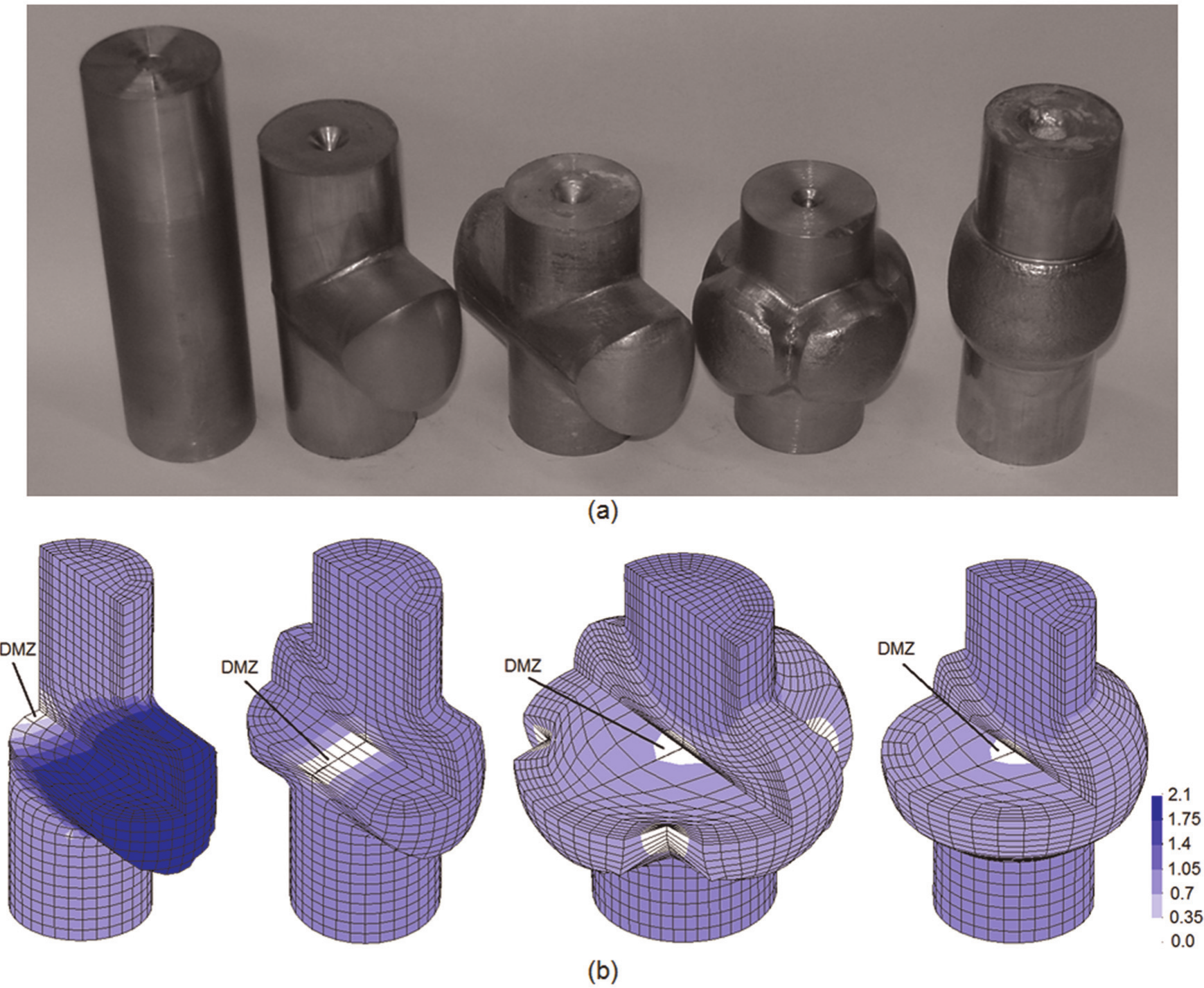
(a) Typical modes of deformation that occur during injection forging of asymmetric and axisymmetric injection forged components and (b) finite element predicted distribution of the normalized total velocity
The finite element results in Figure 6(b) also show that the average normalized total velocity
The experimental evidence of DMZ at the centre of an injection forged component with two radial straight legs is shown in the material flow pattern, as depicted in Figure 7. The flow pattern was obtained by halving one specimen lengthwise, marking one of its faces with a grid pattern, placing the two halves together inside the injection die chamber and forging. It is worth noting that the high-shearing areas characterized by high values of the effective strain rate are found in the regions of the specimen where material flows from the injection die chamber into the die cavity opening.
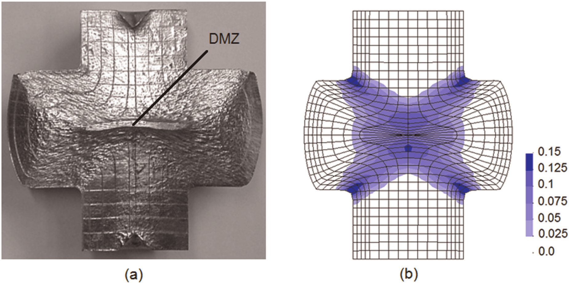
(a) Cross section of a solid branched injection forged component with two radial straight legs showing evidence of dead metal zone (DMZ) at the centre and (b) finite element predicted distribution of the effective strain rate (s−1).
The second set of experiments (cases 5–7 in Table 1) is focused on material flow originated by inappropriate design of double-acting tool systems. The test case 6 shown in Figure 8 was produced in an experimental apparatus equipped with softer springs in the upper half of the floating die and harder springs in the lower half of the floating die. The set-up leads to higher relative velocities of the upper punch and smaller velocities of the lower punch during the first 60% of total ram displacement. The velocities are defined in the above-mentioned reference frame placed in the movable floating die, and the overall kinematics were found to be identical to that of a double-acting tool with a stationary die and two counteracting punches moving towards each other with a velocity ratio of
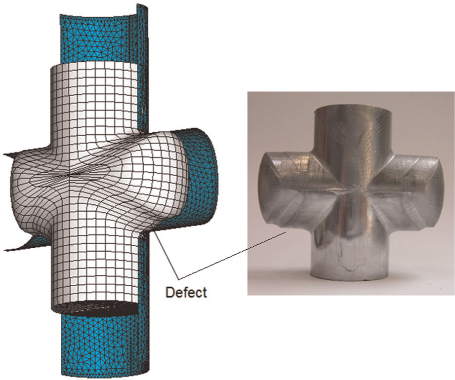
Finite element predicted and experimental shape of a solid injection forged component with two radial straight legs showing loss of symmetry due to combination of a double-acting mode in the first 60% of ram displacement with a single-acting mode in the remaining 40% (case 6 of Table 1).
After the upper springs are totally compressed, the floating die and the upper punch move down together to complete the remaining 40% of total ram displacement. The lower springs continue to be compressed, and the injection forged component is finished by the relative movement between the floating die and the lower counter punch. Resorting, once again to the reference frame placed in the floating die, the last 40% of total ram displacement are similar to performing injection forging in a single-acting tool with the lower punch moving towards a stationary die and upper punch (
The numerical and experimental results that are included in Figure 8 show the DMZ at the end of stroke to be located above the equatorial plane and give evidence of inappropriate material flow due to loss of kinematical symmetry. This leads to the development of a die filling defect and to the production of an inadmissible injection forged component. The result also puts into evidence the importance of understanding the role played by the different active tool components in order to avoid tool concepts and wrong choice of active tool parts that are likely to produce inadmissible injection forged components.
Forging load
Figure 9 shows the numerical and experimental evolutions of the load–displacement curves for test cases 1–4 of Table 1. As seen, the overall agreement is good and allows identifying three different stages in the asymmetric injection forging of solid branched components: (a) the initial non-steady-state upsetting (labelled as ‘A’ in case 1), (b) the transition to steady-state deformation (labelled as ‘B’ in case 1) and (c) the injection forging under steady-state conditions (labelled as ‘C’ in case 1).
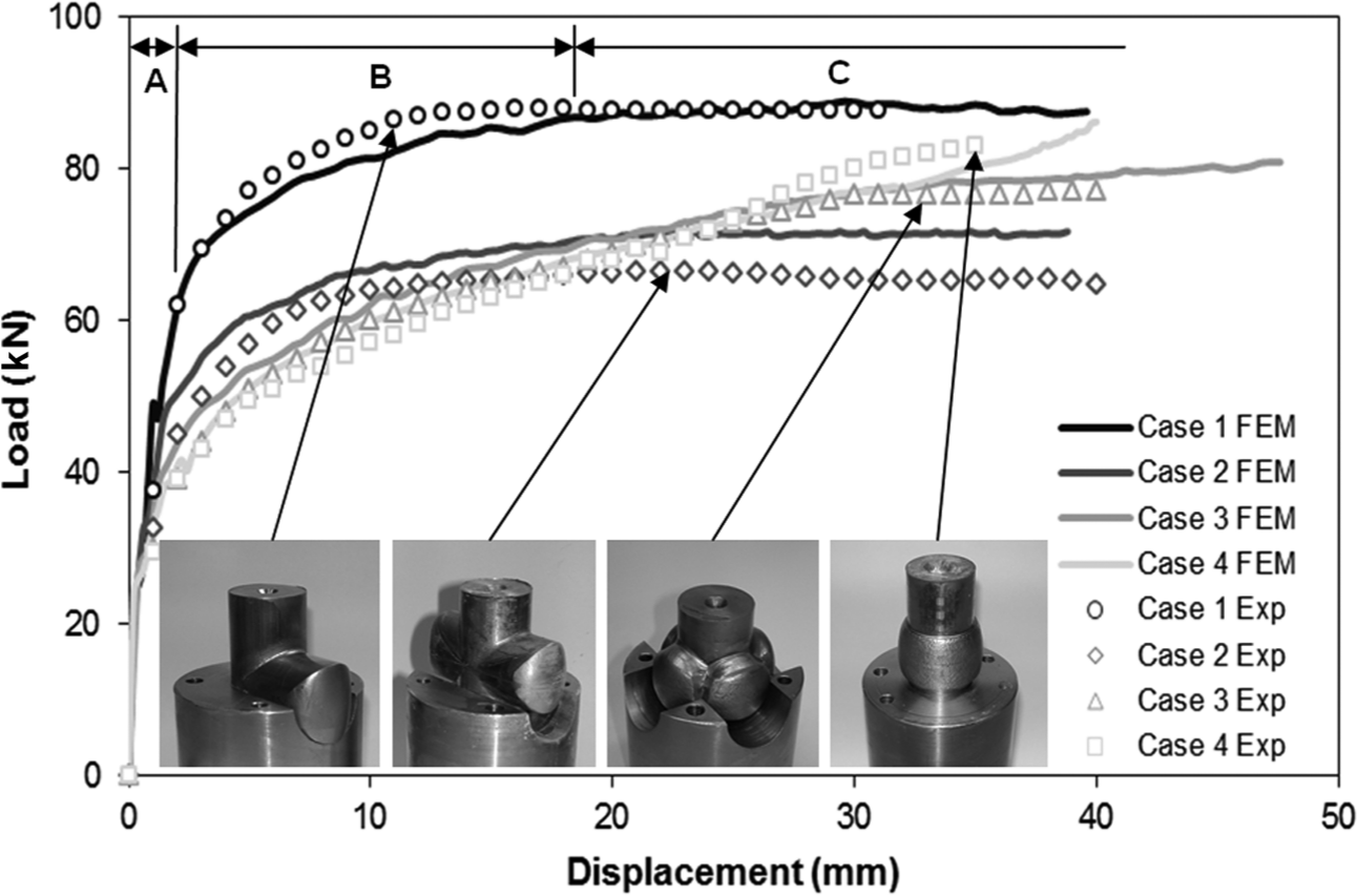
Experimental and finite element predicted evolution of the load–displacement curves for the double-acting injection forging test cases 1–4 of Table 1.
In the first stage, the forging load increases sharply as the specimen is upset to fill out the floating injection die chamber. Subsequently (second stage), injection forging begins and the load grows at a lower rate as material is progressively deformed into the die cavities, and the radial straight legs of the components start to emerge through the die cavity openings. The beginning of the second stage takes place at smaller values of the upsetting load as the number of radial straight legs to be extruded increases (62 kN for case 1 against 45 kN for case 2 and 30 kN for case 3) due to smaller resistance of the die walls to allow radial material flow. There are also differences in the amount of total ram displacement to complete the second stage (i.e. the transition to steady-state deformation) because displacement is slightly larger for case 3 than for cases 1 and 2, which present almost similar values. This may be explained by the fact that material flow in case 1 is hemi-symmetric (along the axial cross section) against that of case 2, while material flow in case 3 is closer to that of axisymmetric flanged components (see reference case 4).
Once the legs have emerged through the die cavity openings and the load becomes constant, steady-state conditions that are typical of the third forming stage prevail until the end of stroke. As shown in Figure 9, the steady-state peak loads for the asymmetric branched components present significant variations with the total number of radial straight legs being approximately 20% higher in case of the injection forged component with a single leg (case 1). The forging load to produce the axisymmetric flanged component (case 4) taken as reference test case grows monotonically with punch displacement and presents very close similarity with the load of case 3 (asymmetric branched component with four legs) during the two initial stages of deformation. Then, while the load in case 4 continues to grow as deformation progresses, the load in case 3 reaches a peak value due to the development of steady-state deformation conditions.
Figure 10 shows the finite element predicted and experimental evolution of the load–displacement curve for case 6 of Table 1 (refer also to Figure 8). As seen, the numerical and experimental curves compare reasonably well and allow distinguishing two main trends: (a) the initial double-acting mode (in the first 60% of ram displacement) and (b) the final single-acting mode (in the remaining 40% of ram displacement). In the first stage, the load–displacement curve has a shape similar in appearance to that of case 2 in Figure 9 with slightly higher values of load due to the loss of symmetry.
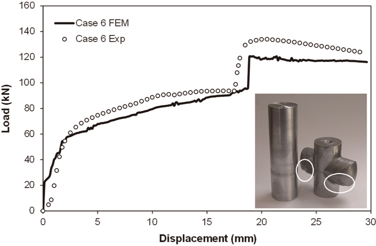
Experimental and finite element predicted evolution of the load–displacement curves for case 6 of Table 1. The enclosed picture shows the defects due to loss of symmetry during injection forging.
However, after the upper springs are totally compressed and the upper punch starts to move down together with the floating die to complete the remaining 40% of total ram displacement, there is a jump in the forging load. This is due to a transition in deformation mechanics from double- to single-acting mode, which increases the aforementioned loss of symmetry and makes plastic flow into the die cavity openings more difficult. As a result of this, steady-state conditions are only reached under significantly higher values of the forging load (roughly 110 kN).
Conclusions
This article is about looking to asymmetric injection forging of solid branched components in the perspective of material flow and forging load requirements. The presentation is supported by numerical modelling and experimentation with a double-acting tool concept equipped with horizontally divided floating dies and spring closing elements that was utilized for producing flanges and solid branched components with different numbers of radial straight legs.
Results show that on the contrary to preconceived notions and ideas that the larger the number of radial straight legs, the higher the injection forging loads, the maximum forging load was found for the asymmetric component with a single radial straight leg. The asymmetric components with larger number of legs behave closer to axisymmetric flanges and, therefore, require larger ram displacements to reach steady-state deformation conditions.
The effectiveness of single-acting tool concepts is found to be limited because velocity and pressure are not transmitted equally to the upper and lower regions of the preforms. This leads to the production of unacceptable injection forged components with symmetry problems and die filling defects. The advantage of utilizing a double-acting tool concept with a single-acting punch, a floating die and spring closing elements is the avoidance of the above-mentioned difficulties and of the need to employ counteracting punches driven by multi-acting presses. However, results presented by the authors show that closing spring elements play a key role in the overall performance of the tool concept and quality of the final component. For instance, the utilization of softer springs in one side of the floating die introduces extra flexibility in the overall tool concept because it allows modifying the relative velocity of the work material located at the upper and lower parts of the preforms, but can easily lead to fabrication problems and defects that are similar to those commonly found in single-acting tool concepts.
Footnotes
Acknowledgements
The work of Bernardo Calado is greatly acknowledged.
Funding
This research received no specific grant from any funding agency in the public, commercial or not-for-profit sectors.