
Abstract
The acquisition of automated manufacturing equipment in developing nations can be expensive. Hence, this article presents the development of a computer numerical control milling machine’s control unit using low-end PIC microcontrollers. The design employs a hierarchy of five low-end PIC microcontrollers connected to a PC. A single master PIC acts as a link between a PC and four slave microcontrollers via a RS232 serial port. One slave PIC is interfaced with the electronics of the spindle drive. The three remaining slave PICs are interfaced with the electronics of the x-, y- and z-axis drives. The low-cost milling machine’s control unit has been constructed and tested. A circle–diamond–square test confirms the functionality of the machine and demonstrates that it does not accumulate error along a milled profile path.
Introduction
Computer numerical control (CNC) milling machines are machines in which the cutter path is controlled numerically by data that have been fed into a program. The program contains coded alphanumeric data that represent relative positions between the worktool and workpart. 1 A numerically controlled system consists of three basic components: part program, machine control unit (MCU) and processing equipment. 2 The MCU in modern numerical control (NC) technology is a microcomputer that stores the program and executes it by converting each command into actions by the processing equipment sequentially.
Typically, milling machines and their control units are expensive. Hence, one of the projects of the Robotics and Automation Group (RAG) at the University of the South Pacific (USP) has been the development of a low-cost customised three-axis CNC milling machine for teaching and research.
The latest computer controllers for CNC feature high-speed processors, large memories, solid state, flash memory, improved servos and bus architectures. Some controllers have the capability to control multiple machines simultaneously. 3 Some examples of such computer controllers are the Sinumerik Systems 800 developed by Siemens and the Fanuc System 5, 6, 10 and 11 product series made by Fanuc (http://www.allmendinger.eu).
With the advance of PC technology, it is now possible to develop PC-based CNC systems, which are open architecture in nature, powerful in capacity and yet affordable. Duffie and Bollinger 4 introduced a multiprocessor system for distributed control. The proposed system displayed the possible interconnection patterns for an interconnected system of semi-independent controllers. Each controller was responsible for a particular section of the CNC system, that is, the x-axis control or spindle speed control, while each node in the system was connected to other nodes or master system.
Rober and Shin 5 applied the PC-based open-architecture NC (CNC) to a milling machine. The controller was designed using commercially available MS-DOS-based software and analog/digital boards. LabWindows (programming language) was used to develop the graphical user interface (GUI) and the system control code in BASIC programming language. The controller was designed specifically for the operation of their machine.
Fei et al. 6 proposed a design of embedded NC device based on Advanced RISC Machine (ARM) and field-programmable gate array (FPGA). Their research looked at the Linux-embedded operating system. Their CNC device combined ARM’s high running speed and precision with the internal logic reconfigurable of FPGA, reducing hardware costs of CNC device, improving the resource utilisation and enhancing the flexibility of the CNC device.
Morales-Velazquez et al. 7 worked on an open-architecture platform based on multi-agent hardware–software units, by developing a novel Multi-Agent Distributed CONtroller (MADCON) system. The hardware units of the proposed system utilise an FPGA-based open architecture. MADCON was retrofitted to a CNC lathe for validation.
In summary, there have been advancements in CNC. In the reviewed literature, the CNC machines utilised were purchased from commercial vendors and were then either retrofitted or modified to suit requirements using expensive electronics. The remainder of this article focuses on our hierarchical architecture for the customised CNC machine using low-end PIC microcontrollers.
Customised CNC machine framework
The general structure for this research study is shown in Figure 1. The GUI software installed on the dedicated PC first takes key control information from the user such as spindle speed and workpiece dimensions. It then requests for the coordinate file that contains the profile of the milling tool path from the user. The coordinate file is checked against the earlier entered workpiece dimensions for any errors, so as to ensure that the coordinates are within the limits.
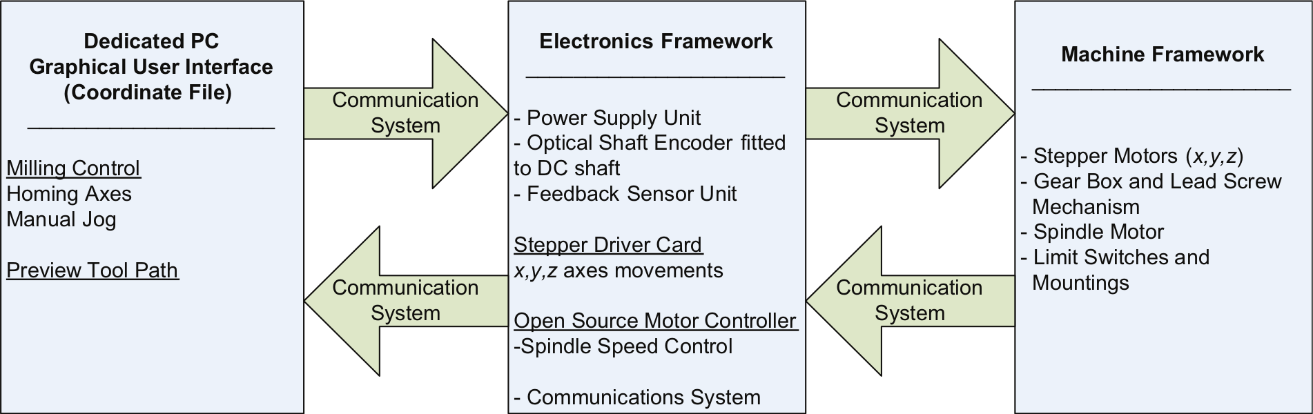
Framework of the PC-based CNC milling machine.
The control information such as spindle speed and workpiece dimensions is communicated to the MCU that is represented by the electronic framework in Figure 1. The MCU is connected to the dedicated PC via its serial port. This is followed by sending the coordinates, one set at a time, from the PC to the MCU in a sequential manner that gets executed by the MCU and the machine framework. The MCU is the driver of the intelligent machine since it is connected to key components of the machine via the relevant electronic interface cards that send appropriate signals to the actuators for execution. The actuators in this machine are a direct current (DC) motor for the spindle and the three stepper motors for movement along the three axes.
The stepper motors help move the worktable on which the workpiece is supported. Two stepper motors are required to effect movement in the x and y directions, respectively. The third stepper motor actuates the movement of the spindle DC motor in the z direction. Figure 2 illustrates the milling machine’s worktable (x- and y-axes) and spindle (z-axis) components.
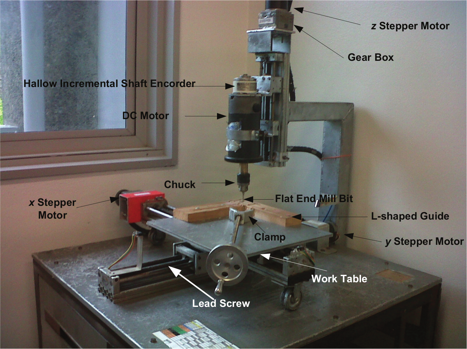
Components of the x-, y- and z-axes of the milling machine.
Hierarchical PIC architecture
A block diagram of the hierarchical architecture using PIC microcontrollers is shown in Figure 3. A total of five microcontrollers are used in the arrangement. A linear shared data bus is employed to communicate between the master and slave controllers.
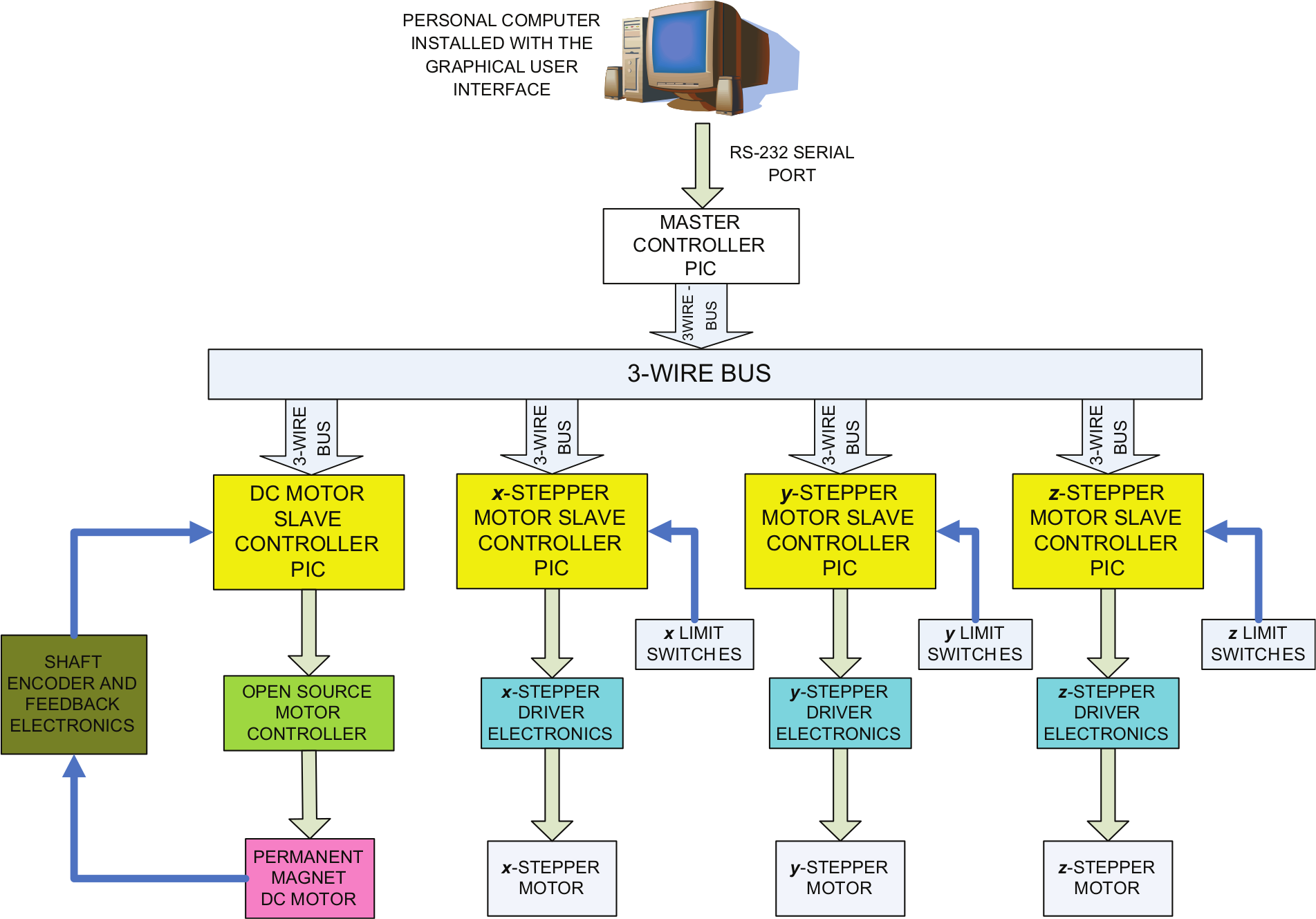
Block diagram of the hierarchical PIC architecture.
The PC, which acts as a front end and runs the GUI program, is responsible for gathering important milling operation parameters such as cutting speed and workpiece dimensions. The GUI has a facility to upload a data file containing the x, y and z coordinates of the surface to be milled. The MCU is represented by all components shown in Figure 3 with the exception of the PC and all the electromechanical actuators. The milling operation parameters and the x, y and z coordinates are communicated to the MCU via the serial RS232 port that then controls the machine accordingly. The MCU calculates the various machine movement coordinates from the original x, y and z coordinates for positioning the worktable and spindle. The positioning system drives the x, y and z stepper motors to move in the required directions.
The justification of having a master controller is that this machine has been designed with the view of further upgrading so that it could be controlled over the Internet. For this purpose, the master controller could be replaced with a mini-PC such as the ‘Raspberry Pi’ (http://www.raspberrypi.org/).
Communication
The hierarchical architecture utilised in the CNC milling machine requires two different types of communication systems. One is from the PC to the milling machine. The other is among the master and slave controllers.
PC to CNC milling machine communication
The PC is connected to the CNC milling machine via the master controller in the machine’s hierarchical architecture, as shown in Figure 3. All controllers (master and slaves) are PIC16F877 8 bootloader boards that have an on board 9-pin connector and a MAX232 IC for serial port (RS232) communication. This facility is used by the CNC milling machine to communicate with the PC. The master controller communicates with a GUI program specially developed for the CNC milling machine.
Communication between master and slave controllers
The master controller communicates with the slave controllers in a serial manner over a three-wire bus. 9 The first two lines are used for synchronisation while the third line is used for actual data communication. Data are sent from the master PIC to the slave PICs serially over the three-wire bus. A process of encapsulation occurs on the master PIC and involves taking the input data communicated from the GUI and converting it to a packet for the purpose of serial transmission to the slave PICs. The encapsulated packet is 9 bytes long. The slave PICs receive and decapsulate the 9-byte packets to perform the corresponding control actions. This communication sequence is shown in the flowchart in Figure 4.
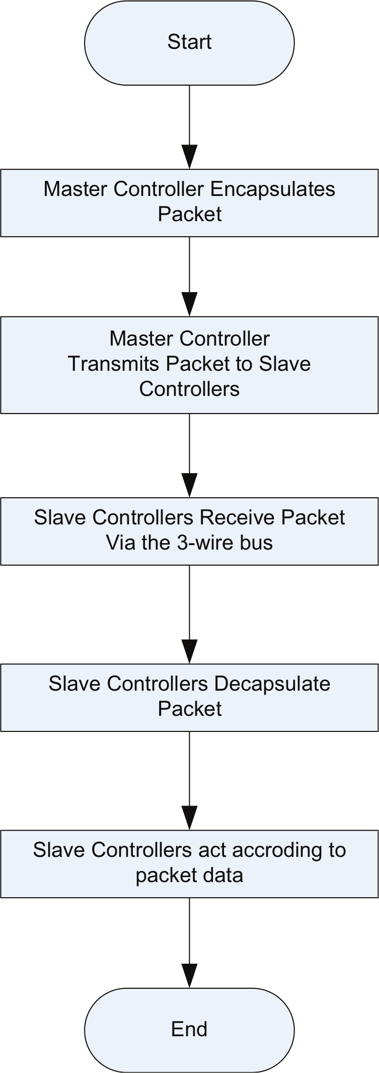
Sequence of operations between the master and slave controllers.
Two types of packets are used in the communication between the master and slave controllers. These are the initialisation packet and the coordinate packet. The initialisation packet is a 9-byte packet that consists of a number of key parameters that are used to configure the MCU to a desired initial state before milling operations begin. These parameters include the following: finding the home configuration, height of the workpiece, motor speed and motor direction. The coordinate packet is also 9 bytes and consists of the x, y and z coordinates that are used by the x, y and z stepper motor slave controller PICs to calculate the number of steps and the direction in which each stepper motor moves.
Experiments
Conventional testing of the accuracy of milling machines involves the use of a coordinate measuring machine (CMM).2,10 However, testing of the developed machine had to be done without a CMM as one was not available. Hence, another technique reviewed in the literature was the circle–diamond–square test.2,10 In this test, a diamond is milled inside a circle that is itself milled inside a square. Each of these shapes is milled at different depths to allow for visual inspection.
In this test, the four vertices of the diamond must perfectly meet the circumference of the circle. The circumference of the circle must in turn touch the side of the square at the point where the vertices of the diamond touched the circle. These intersections of the three shapes at the four instances will indicate that the CNC milling machine is milling within an accepted error range where there are no significant accumulated deviations from the path that can be visually observed.
A circle–diamond–square profile with circle diameter and square width of 100 mm was milled, as shown in Figure 5, and this test was carried out five times. When the milled workpieces were visually inspected, it was observed that the four vertices of the diamond touched the circumference of the circle that in turn touched the square. This demonstrates that the CNC milling machine does not accumulate error along a milled profile path.

Top view of milled circle–diamond–square profile.
Further experimentation and testing will involve milling a range of objects. Overseas universities with manufacturing research laboratories will be approached for CMM testing to enhance the validation of the system.
Conclusion
A hierarchical architecture for a customised three-axis CNC milling machine’s control unit using low-end PIC microcontrollers has been presented. The design employs five low-end PIC microcontrollers where a master PIC acts as a link between a PC and four slave PICs. The four slaves are responsible for the control of the spindle and worktable actuation systems. Communication between the master and slave controllers is achieved using a three-wire bus 9-byte packet switching system. The master communicates with a PC using the RS232 protocol.
Results from a circle–diamond–square test indicate that the hierarchical architecture is functional without accumulated deviations from the desired milling path. Future study includes performing further tests to evaluate the machine’s accuracy and the replacement of the master PIC with a Raspberry Pi for Internet-based control.
Footnotes
Funding
This study was funded by the Faculty of Science, Technology, and Environment Research Committee of the University of the South Pacific.