
Abstract
Because of its unique properties, potassium dihydrogen phosphate crystals are widely used for electro-optical applications. Slicing is needed to make potassium dihydrogen phosphate crystal lens with desired shapes. However, reported studies on slicing of potassium dihydrogen phosphate crystal are scarce. This article presents an experimental investigation on slicing of potassium dihydrogen phosphate crystals. Output parameters studied include surface roughness, flatness error, parallelism error, and subsurface damage. Effects of wire sawing input variables (feed rate and diamond grit size) on output parameters are investigated. Comparisons of wire sawing and band sawing are also made.
Keywords
Introduction
Because of its unique properties, potassium dihydrogen phosphate (KDP) crystals are widely used for electro-optical applications.1–3 For example, large KDP crystal parts (with a size of 410 mm × 410 mm × 10 mm) are used as optical harmonic generation lens and Pockels electro-optical switches for the application of inertial confinement fusion.4,5
Table 1 lists some mechanical properties of KDP in comparison with three commonly used materials (tool steel, alumina, and silicon carbide). It shows that KDP has much lower hardness and fracture toughness. In addition, KDP is deliquescent. All these make it a difficult-to-machine material.8–10
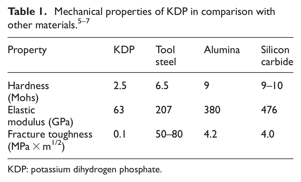
KDP: potassium dihydrogen phosphate.
An important machining process for KDP is the slicing of workpieces into desired shapes. Currently, slicing methods include outer diameter (OD) sawing, 11 inner diameter (ID) sawing, 12 band sawing, and wire sawing. 13 OD sawing uses a thin blade with diamond abrasives plated on its OD. As the blade diameter gets larger, the deflection at the edge of the blade will become larger under the same force. This can cause the blade to vibrate with larger amplitude, resulting in higher kerf loss. 11 ID sawing uses a hollow blade with diamond abrasives plated on its ID. Compared with OD sawing, ID sawing has higher stiffness, lower kerf loss, and better slicing quality. However, the blade stiffness is still a bottleneck when the blade diameter increases to a certain value. This limits its application in slicing large-size KDP crystals. 14 Band sawing uses either a steel band saw with teeth or a steel band saw with plated diamond abrasives. Although it has a high kerf loss, this method is still used to slice large-size KDP workpieces.
Compared with the aforementioned slicing methods, wire sawing is especially suitable for slicing large KDP crystal materials, primarily due to its lower kerf loss. 15 There are two types of wire sawing, free abrasive and fixed abrasive. In comparison with fixed abrasive wire sawing, free abrasive wire sawing takes longer time to cut the same size of KDP crystals. 14 It has other problems such as embedment of the abrasive particles into KDP workpiece surfaces and the environmental pollution when disposing the used slurry.
Although wire sawing has many advantages in slicing KDP crystal materials, 16 there is only one reported study on the subsurface damage in wire sawing of KDP. 17 There are no reported studies about the effects of input variables (such as feed rate and diamond grit size) on workpiece surface profile and subsurface damage in wire sawing of KDP.
This article reports an experimental investigation using fixed abrasive wire sawing of KDP. Output parameters include surface roughness, flatness error, parallelism error, and subsurface damage. Effects of wire sawing input variables (feed rate and diamond grit size) on output parameters are investigated. Comparisons of wire sawing and band sawing are also made.
Experimental conditions
KDP workpieces
KDP workpieces were obtained from Shandong University (Jinan, Shandong, China). The following two sizes of KDP workpieces were used: 150 mm × 105 mm × 6 mm and 15 mm × 6 mm × 3 mm. The crystalline surface was (001).
Experimental setup and conditions for wire sawing
Wire sawing experiments were conducted on a reciprocating diamond wire sawing machine. Figure 1 illustrates the experimental setup schematically.
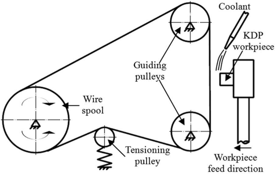
Illustration of wire sawing experimental setup.
Two types of diamond plated stainless steel wires were obtained from Kejing Automation Equipment Company (Shenyang, Liaoning Province, China). The first type had diamond grit size of 40 µm and wire diameter of 0.3 mm. The second type had diamond grit size of 60 µm and wire diameter of 0.4 mm. An scanning electron microscope (SEM) picture of the second type is shown in Figure 2.
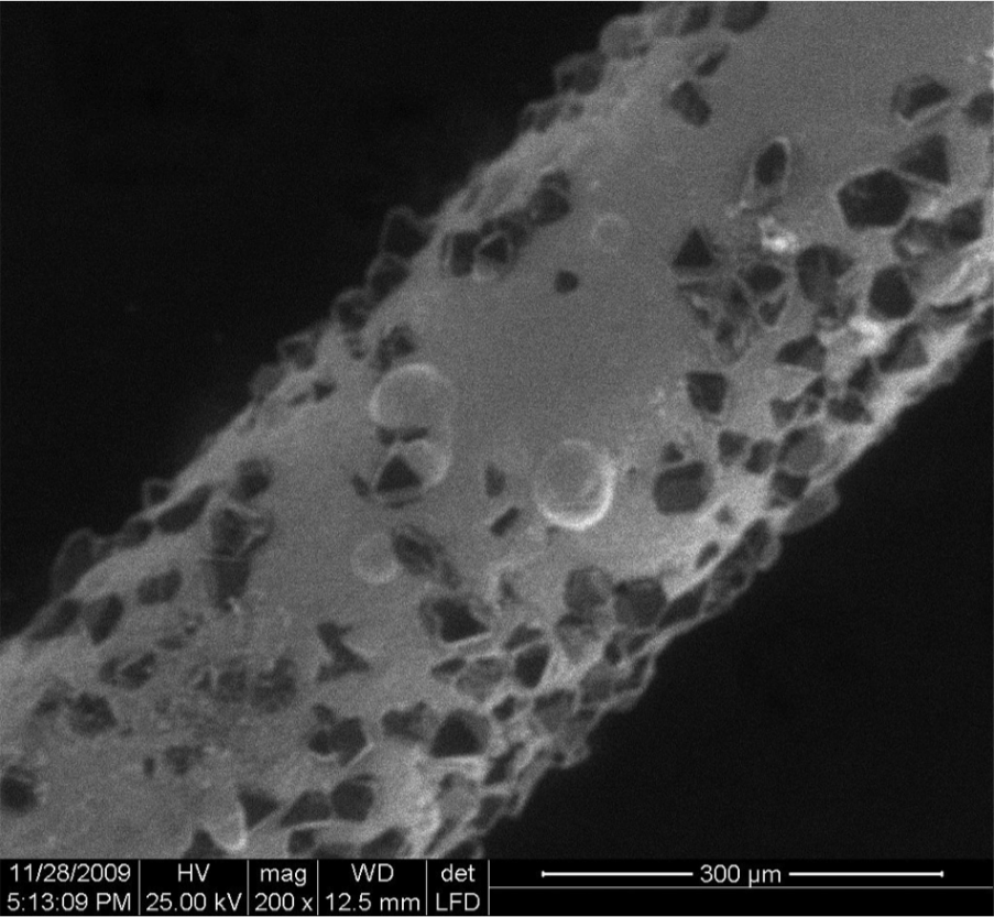
SEM picture of a diamond plated wire (diamond grit size = 60 µm; wire diameter = 0.4 mm).
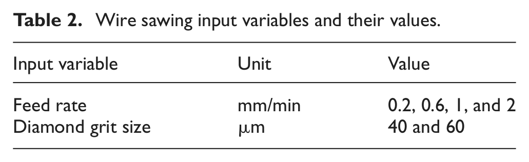
Two input variables (feed rate and diamond grit size) were investigated. Table 2 shows their values used in the wire sawing experiments. Wire speed was 60 m/min. If the wire length was 65 m, the reciprocating period would be 135 s (including the time for the wire to slow down and change its moving direction). The coolant (mineral lubricant) had a viscosity of less than 10 cSt and was supplied to the slicing area with a flow rate of 180 mL/min. In order to slice workpiece with good flatness error, the tension stress was selected to be as close as possible to the maximum allowable tension stress while still could maintain a reasonable wire life. The maximum allowable tension stress was determined by prior experiments. A tension stress higher than the maximum tension allowable would result in an early broken of the wire. Too low a tension stress would result in a longer wire life but a sliced surface with poor flatness error.
Wire sawing input variables and their values.
Experimental setup and conditions for band sawing
A vertical band sawing machine (North Tiger, Beijing, China) was used. Its picture is shown in Figure 3. It is capable of sawing workpieces as large as about 500 mm in height.

Picture of band sawing machine.
Figure 4 shows the two types of band saws used. One had regular teeth and the teeth per inch (TPI) was 10, and the other had plated diamond abrasives with grit size of 60 µm. The thickness of these band saws was 1.2 mm and blade width was 40 mm. When slicing, the band saw moving speed was 120 m/min, and the feed rate was 1.33 mm/min. The coolant used was the same as that used in wire sawing.
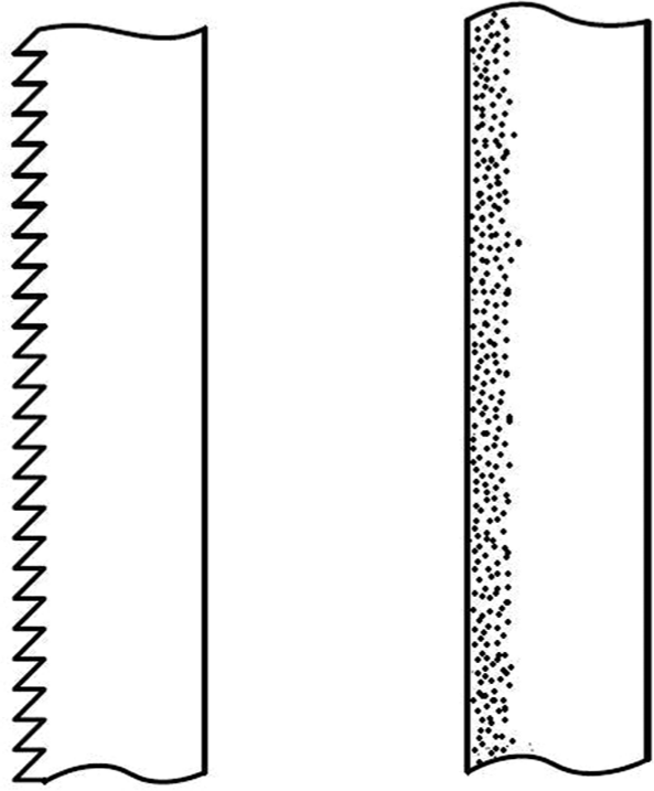
Two types of band saws: (a) band saw with teeth and (b) band saw with plated diamond abrasives.
Measurement procedures
Surface roughness was measured on sliced surfaces along the feed direction using a surface profilometer (Talysurf CSI 2000; Taylor Hobson Ltd, Leicester, UK). The KDP workpiece was fixed on the worktable of the profilometer. Then the probe (diameter of the styles was 1 µm) was adjusted to touch the workpiece surface with very small contact force. Then, the worktable started to move at a speed of 0.2 mm/s with the cutoff distance of 2.5 mm. The surface roughness in this study was characterized by average surface roughness (Ra) and the peak-to-valley roughness (Rz).
Flatness error measures the deviation of a sliced surface to an ideal surface that is perfectly flat. Parallelism error measures how parallel the two sliced surfaces are. Both flatness and parallelism errors were measured using a PRISMO Navigator Measuring Center (model PRISMO7S-ACC; Zeiss, Oberkochen, Germany) at Modern Manufacturing Technology Institute of Dalian University of Technology.
Subsurface damage (including dislocations and cracks) was measured using the cross-sectional polishing and etching methods. As shown in Figure 5, two sliced surfaces (facing each other) were glued together. As illustrated in Figure 6, polishing was done on the surfaces perpendicular to the sliced surfaces and parallel to the workpiece feed direction. The polishing slurry was the mixture of SiO2 (grits size ranged from 7 to 20 nm) and alcohol. The polishing pad was black finishing leather rotating at a speed of 80 r/min. Surface roughness (Ra) of the polished KDP cross-sectional surface was around 5 nm. The etchant was prepared by mixing 60 mL of glacial acetic acid, 5 mL of deionized water, and 4 drops of concentrated sulfuric acid. After etching, damaged areas on the polished surface became visible since their etching rate was faster than undamaged ones. 18
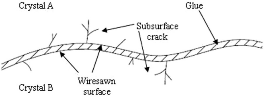
Cross-sectional polishing method for subsurface damage measurement.
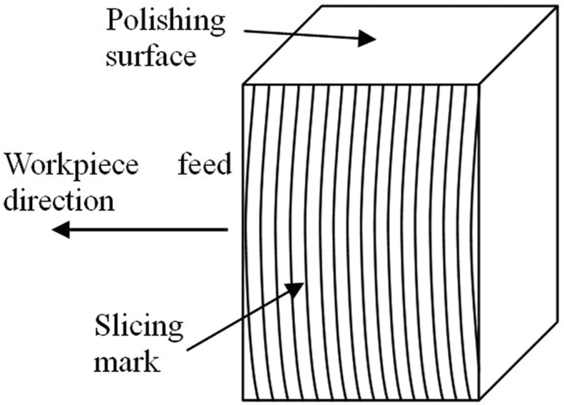
Illustration of polishing surface.
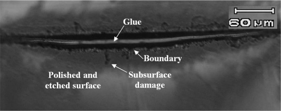
Figure 7 shows the subsurface damage observed using the cross-sectional polishing and etching methods. The depth of the deepest crack was the maximum depth of the slicing-induced subsurface damage.
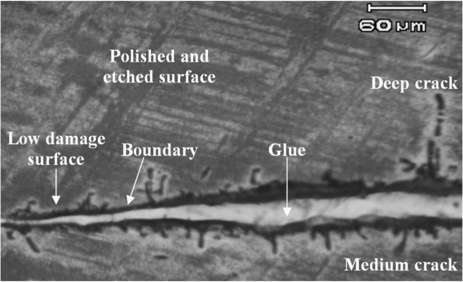
Subsurface damage observed using the cross-sectional polishing and etching method.
Results and discussion
Sliced surface profiles
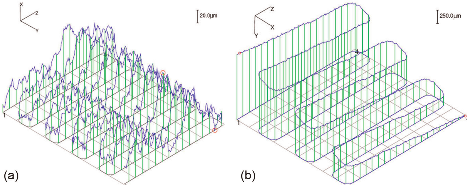
Figures 8 and 9 show the wire sawing sliced surface profiles measured along the workpiece feed direction.
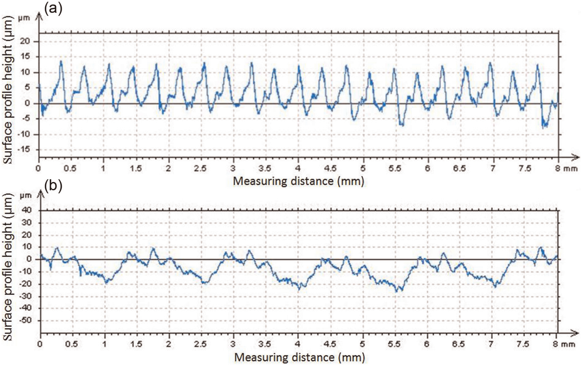
Wire sawing sliced surface profiles at different feed rates: (a) feed rate = 0.3 mm/min and (b) feed rate = 0.6 mm/min (workpiece size = 15 mm × 6 mm × 3 mm; diamond grit size = 40 µm).
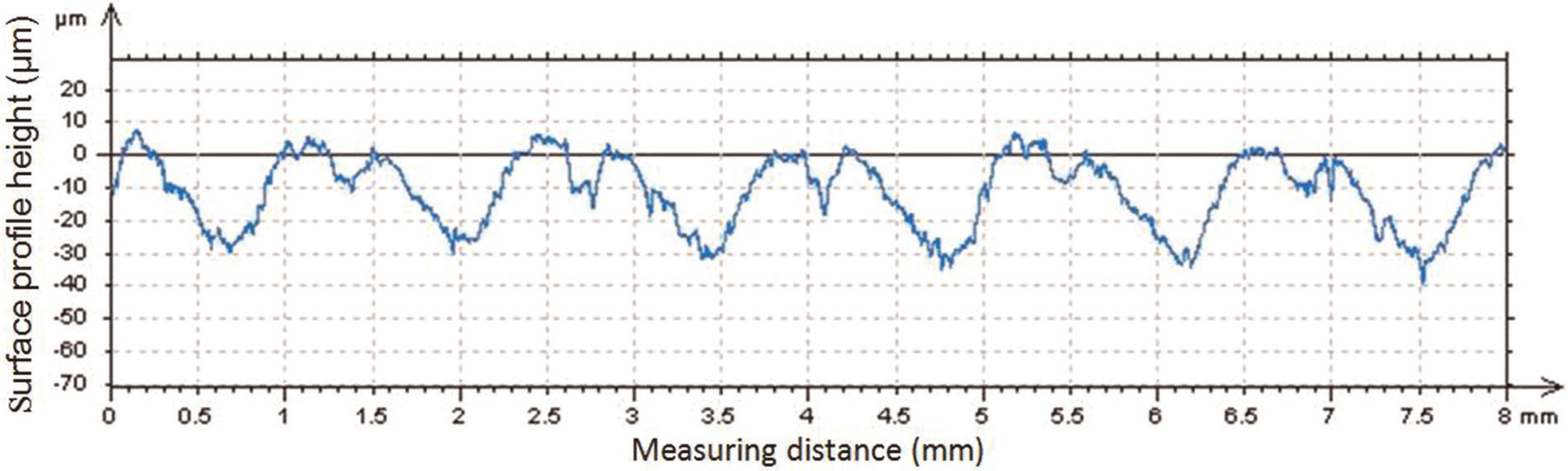
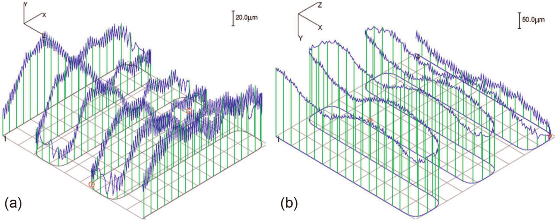
Wire sawing sliced surface profile (feed rate = 0.6 mm/min; workpiece size = 15 mm × 6 mm × 3 mm; diamond grit size = 60 µm).
All sliced surface profiles show a periodical feature. Based on the calculated relationship between feed rate and wire sawing reciprocating period, it was found that the periodical feature was caused by the wire sawing reciprocating action (the wire changed its moving direction). For example, the wire that was 65 m long would need about 135 s to finish a cycle of reciprocation (wire speed was 60 m/min). During this period of time, the workpiece was fed about 1.35 mm (calculated by multiplication of time and feed rate that was 0.6 mm/min), approximately equal to the peak-to-peak distance of the periodical feature, as shown in Figure 9.
Surface roughness
Effects of feed rate on surface roughness in wire sawing of KDP are shown in Figure 10. As feed rate increased from 0.3 to 0.6 mm/min, both Ra and Rz increased from Ra = 3.52 µm and Rz = 11.1 µm to Ra = 5.29 µm and Rz = 30 µm.
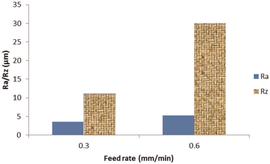
Effects of feed rate on surface roughness (workpiece size = 15 mm × 6 mm × 3 mm; diamond grit size = 40 µm; wire speed = 60 m/min).
Effects of diamond grit size on roughness are shown in Figure 11. Surface roughness (Ra) and peak-to-valley roughness (Rz) were higher when larger diamond grits were used.
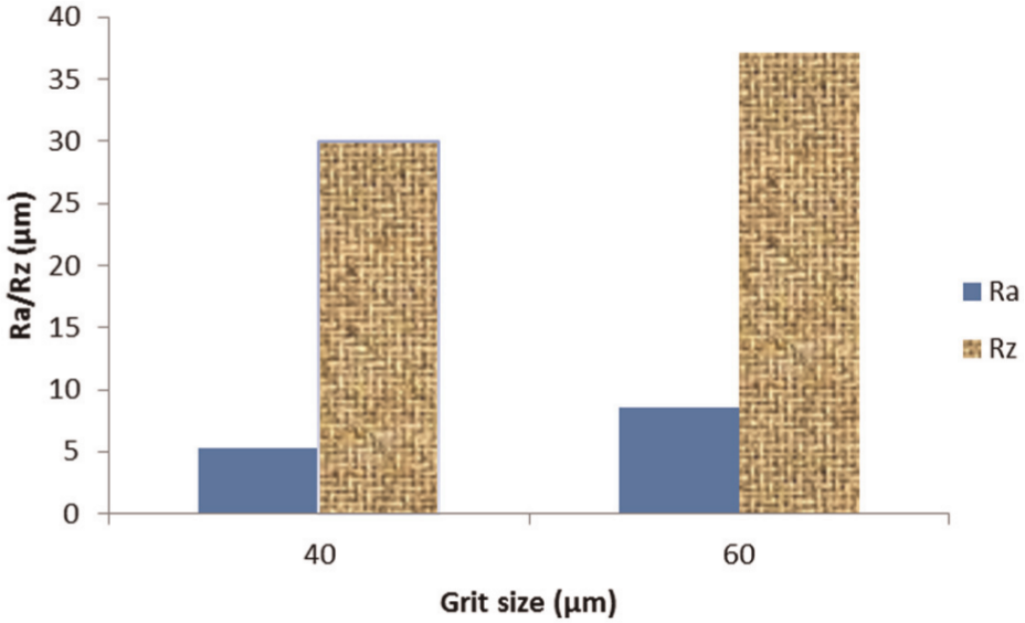
Effects of diamond grit size on surface roughness (Ra) and peak-to-valley roughness (Rz) (workpiece size = 15 mm × 6 mm × 3 mm; feed rate = 0.6 mm/min; wire speed = 60 m/min).
Flatness and parallelism errors
Figure 12 shows the effects of feed rate on flatness error in wire sawing. As the feed rate increased, flatness error became higher.
Effects of feed rate on flatness error (workpiece size = 15 mm × 6 mm × 3 mm; diamond grit size = 60 µm; wire speed = 60 m/min).
In wire sawing, as the workpiece is fed toward the wire, the wire in contact with the workpiece bended like a bow string due to the pushing force from the workpiece. Therefore, the slicing marks left on the workpiece surface became curved. Figure 13 is the photograph of a sliced surface showing one curved slicing mark. Before the photograph was taken, the curved slicing mark was traced by a pencil to make it more visible.
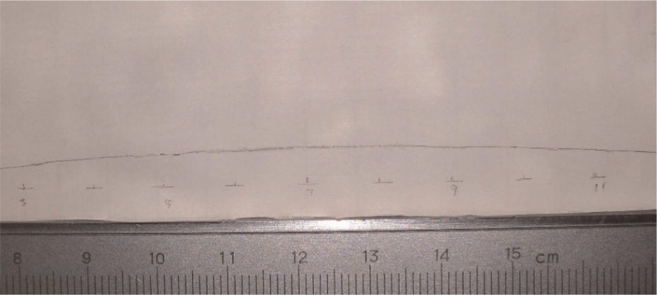
Curved slicing mark (workpiece = 150 mm × 105 mm × 6 mm; diamond grit size = 40 µm; feed rate = 0.3 mm/min).
To compare the slicing quality between wire sawing and band sawing (using the band saw with teeth), flatness and parallelism errors for sliced workpiece by band sawing were also measured and are shown in Figure 14. Flatness and parallelism errors were 90 µm and 1.26 mm, respectively.
Flatness and parallelism of band sawing sliced surfaces (feed rate = 1.33 mm/min): (a) flatness and (b) parallelism.
In comparison, wire sawing sliced surfaces had large flatness error but lower parallelism error, as shown in Figure 15. The flatness error of the wire sawing sliced surface was 129 µm when the feed rate was 0.3 mm/min and 106 µm when the feed rate was 0.6 mm/min. The parallelism error between two wire sawing sliced surfaces was 0.232 mm. Figure 16 shows the comparison of flatness and parallelism errors between wire sawing and steel band sawing.
Flatness and parallelism of wire sawing sliced surfaces (feed rate = 0.6 mm/min): (a) flatness and (b) parallelism.
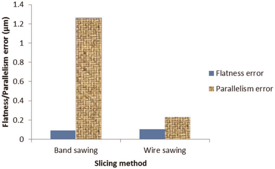
Comparison of flatness and parallelism errors between band sawing and wire sawing.
Subsurface damage
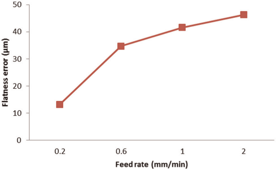
The effects of feed rate on subsurface damage in wire sawing (diamond grit size = 60 µm) are shown in Figure 17. As the feed rate increased from 0.2 to 0.6 mm/min, subsurface damage increased significantly. However, when the feed rate was in the range of 0.6–2 mm/min, subsurface damage remained relatively constant. Figure 18 shows subsurface damage caused by wire sawing (diamond grit size = 40 µm) when feed rate was 0.3 mm/min. The maximum value was 26.7 µm. In comparison, subsurface damage depth caused by wire sawing with larger diamond grit size (60 µm) was much deeper than that with smaller diamond grit size (40 µm).
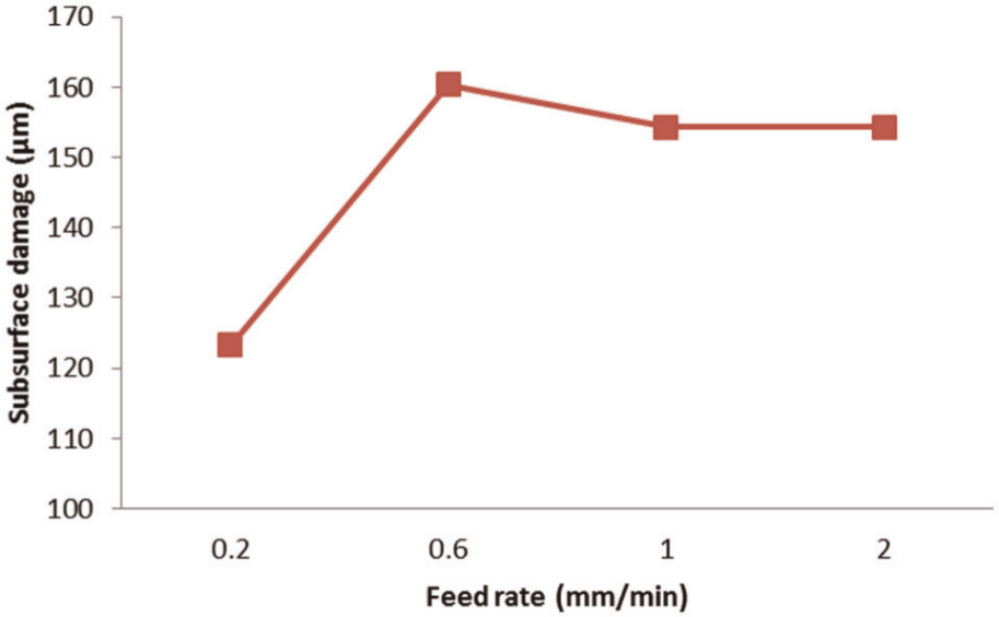
Effects of feed rate on subsurface damage in wire sawing (workpiece size = 15 mm × 6 mm × 3 mm; diamond grit size = 60 µm; wire speed = 60 m/min).
Subsurface damage of wire sawing sliced surface (workpiece size = 150 mm × 105 mm × 6 mm; diamond grit size = 40 µm; feed rate = 0.3 mm/min).
Figure 19 shows subsurface damage on KDP surfaces sliced by band sawing. As shown in Figure 20, the subsurface damage (211 µm) caused by band sawing with teeth was much higher than that (80 µm) caused by band sawing with plated diamond abrasives.
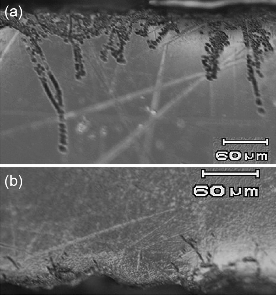
Subsurface damage of band sawing sliced surfaces: (a) sliced by band saw with teeth and (b) sliced by band saw with plated diamond abrasives.
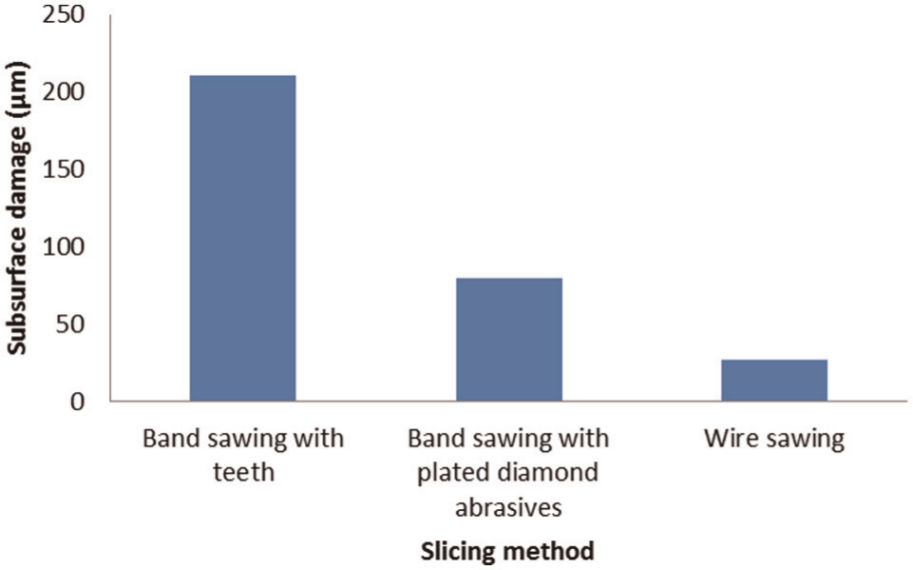
Subsurface damage comparison between different slicing methods.
In order to remove all the subsurface damage and the geometrical imperfection (flatness and parallelism errors) induced by slicing, subsequent machining processes are needed after slicing. The amount of material to be removed would be determined by the largest of subsurface damage, flatness error, and parallelism error. For band sawing, since the largest was parallelism error (1.260 mm), the minimum amount of material that should be removed by the subsequent finishing processes would be 1.260 mm. For wire sawing, the parallelism error was 0.232 mm; therefore, the minimum amount of material that should be removed would be 0.232 mm. In summary, wire sawing requires less material to be removed by subsequent finishing processes, which saves raw crystal material and reduces the machining time after slicing.
Conclusion
This article reports an experimental investigation on wire sawing of KDP. Surface roughness, flatness error, parallelism error, and subsurface damage were studied. Comparisons with band sawing were also made. The following major conclusions can be drawn:
In wire sawing, as feed rate and diamond grit size increased, both surface roughness and subsurface damage increased.
Compared with band sawing, wire sawing produced high flatness error but lower parallelism error.
The amount of the material, required to be removed in subsequent machining processes after wire sawing, was much less than that needed after band sawing.
Footnotes
Funding
This study was supported by the National Natural Science Foundation of China (grant number 50535020) and the State Key Laboratory of Crystal Materials of Shandong University (grant number KF0904).