
Abstract
Microlens arrays are a vital part of today’s optical systems, and advances in fabrication technology have broadened microlens array applications. The roll-to-roll fabrication process has an advantage in its fast and mass replication of microstructures, and it is a good fit for fabricating devices based on flexible substrates. To investigate the roll-to-roll process in the making of microlens arrays of different radii in the same process, this study designs microlens arrays with radii ranging from 55 to 240 µm and with a height of 15 µm. The material for the lens is an ultraviolet curable resin with a refractive index of 1.5. The lens pattern is first transferred to an 80-µm-thick stainless steel sheet through an etching process. The patterned sheet is then wrapped around a stainless steel roller for roll-to-roll fabrication of the microlens array film. The substrate for the microlens array is a polyethylene terephthalate film 188 µm in thickness. When operating with a substrate forward speed of 0.251 m/min (1 r/min) and imprinting pressure of 0.6 MPa, the replication rates achieved for both the radius and the height of the microlens arrays are about 97%. Single-peak filling patterns are found with the small radii lenses, while dual-peak patterns are found in lenses with bigger radii. Overall, this study demonstrates the potential of roll-to-roll in three-dimensional pattern fabrications and its application in microlens array optical film fabrication.
Introduction
Microlenses are small lenses, generally with a diameter of less than 1 mm and often as small as 10 µm. Microlens arrays (MLAs) play an important role in today’s optical systems; they are widely used in the optical and biomedical fields, especially in optical applications, such as fiber communication, scanning systems, charge-coupled device (CCD) sensors, digital cameras, and display systems. For example, the light guide plate of liquid crystal display (LCD) backlight module uses an MLA to improve its luminance performance and its light-guiding efficiency. Advances in microfabrication technology have enabled microlenses to be fabricated within a tight tolerance. Several microfabrication techniques have been applied in making MLAs, including thermal reflow,1–4 gray scale mask, 5 microtransfer molding, 6 excimer laser, 7 reactive ion etching, 8 thermal pressing, 9 ultraviolet curing of polymer, 10 ink-jet technique,11,12 modified ultraviolet (UV) curing, 13 injection molding, 14 hot embossing,15–17 and nanoimprint lithography (NIL). 18 Among these processes, injection molding, hot embossing, and NIL have the advantages of a high replication rate and low fabrication cost demanded by industry.
The roll-to-roll (R2R) microfabrication process evolved from the nanoimprint process, making it possible for low cost, large area, and flexible devices to be produced in a continuous process, making it even more advantageous. R2R inherited the high-resolution feature of traditional NIL as it is also based on a mechanical embossing approach but with the speed of nanopatterning increased by at least one or two orders of magnitude. 19 For cost-effective fabrication of large area products, R2R manufacturing remains an ideal method. 20 UV radiation curing technology has many advantages, such as a high curing speed that reduces the cycle time, low energy costs as the polymerization proceeds at room temperature, and no pattern shift due to the absence of any mismatch of coefficients of thermal expansion of the mold and the substrate. These factors led to the quick acceptance of UV curing in the nanoimprinting field. 21 The integration of UV curing and R2R has been applied in the making of optical films,22–24 thin film solar panels, 25 and organic light-emitting diode (OLED). 26 Micro-optical films for LCD applications, such as MLA film, lenticular lens sheets, and antireflective optical films, have been successfully fabricated using R2R. 20 Previously, most of the microstructures fabricated through R2R were of one size.22–24 For LCD applications, arrays of the same dimension as the microlens or microlenses of different sizes are possible. The filling behavior of the polymer in the embossing process depends on the polymer’s properties 27 and the cavity geometry. 28 Variations in the embossing tool geometry and polymer during the viscous flow distinguish different flow mechanisms. 28 Both single-peak and dual-peak patterns have been found in the embossing process. The filling pattern variation, which occurs in the embossing process, should also occur in the R2R fabrication process. The rotation of the imprinting roller makes the process even more complicated. To investigate R2R microfabrication in the making of MLAs of different radii in this study, lens arrays were designed and the wet etching process was applied to transfer the patterns to an 80-µm-thick stainless steel stamper; the stamper was then wrapped around the roller mold for further R2R imprinting processing. The effect of the processing parameters on the replication of lenses of different radii was also investigated.
MLA design
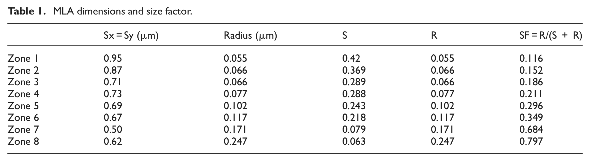
The patterns of the MLAs designed in this study are shown in Figure 1. There were eight MLAs in eight different zones of the same zone size. The microlens pattern was fabricated on a polyethylene terephthalate (PET) substrate using UV curable resin. As shown in Figure 1, the dimensions of the PET were 188 µm in thickness, 50 mm in length, and 40 mm in width. In each zone, an array of microlenses of equal size was assigned; the radii are listed in Table 1, along with the distances between the centers of the microlenses for both the x and y directions, represented as Sx and Sy, respectively. The height of the microlens designed was 15 µm.
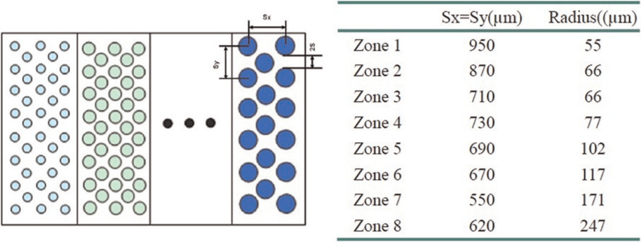
Schematic picture of MLA arrangement and dimensions.
MLA dimensions and size factor.
Experimental setup
R2R microfabrication processing machine
A self-developed R2R microfabrication prototype machine, as shown in Figure 2, was used in this study. It consisted of a substrate installing and pickup mechanism, UV resin printing mechanism, and UV curing light source. Figure 3 shows a schematic picture of the R2R microfabrication process. This R2R machine was situated in a clean room, and the environment was kept at 21 °C when operating the R2R imprinting machine in this study.
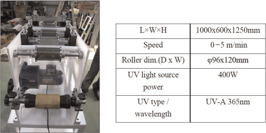
Picture and specification of the R2R equipment used in this study.
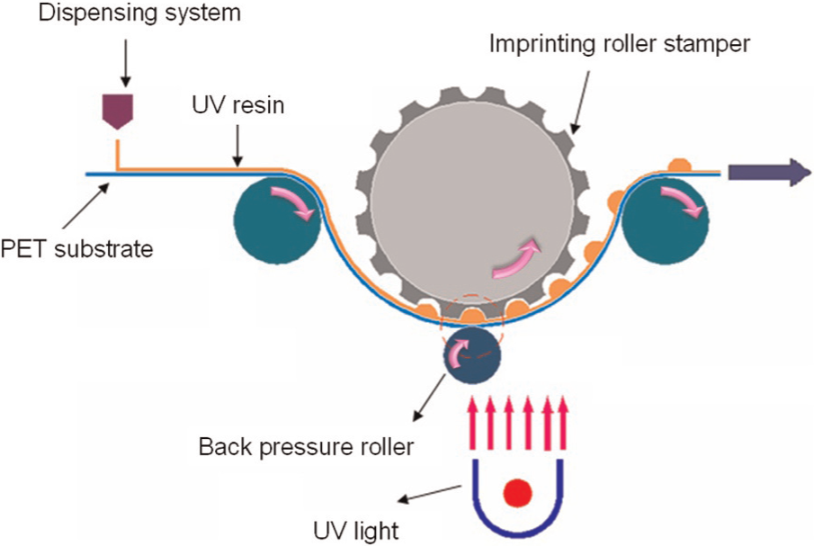
Schematic picture of R2R continue imprinting process.
Fabrication of roller stamper
Two typical MLA stamper fabrication methods are wet etching and Lithography, Electroplating, and Molding (LIGA)-like technology with thermal reflow. With LIGA-like technology, the microlens pattern can be fabricated with excellent surface roughness; however, time-consuming electroforming is required to complete the stamper. Thus, the wet etching technique was developed as a possible solution for producing a large area and low cost nanopattern stamp for ultraviolet-based nanoimprint lithography (UV-NIL). 29 In this study, the wet etching process was selected for making the stamper since a large area and low cost are the two major concerns for R2R microfabrication applications. The processing flow for making the imprinting stamper is shown in Figure 4. A plastic mask was made prior to the etching process. After the photoresist spinning, exposure, and development steps, the microarray patterns, with radii ranging from 55 to 247 µm and a depth of 15 µm, were transferred to an 80 µm stainless steel sheet which was then wrapped around the roller to form a roller stamper, as shown in Figure 5.
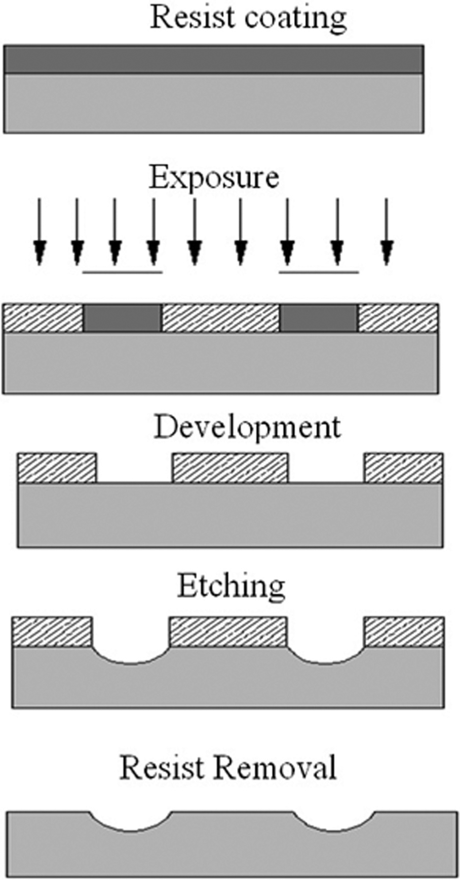
Lithography process flow chart for making the stamper.
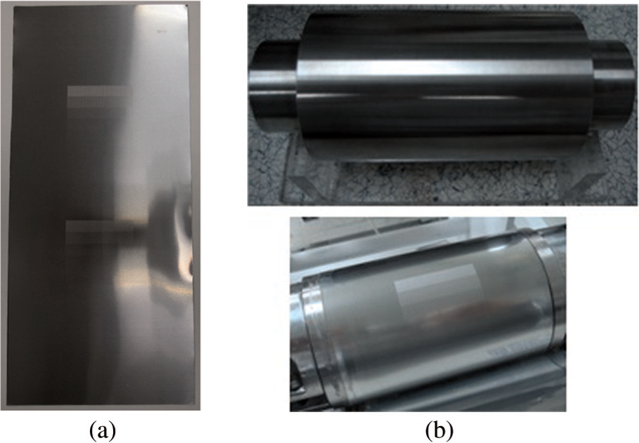
Pictures of roller stamper: (a) stainless stamper and (b) roller and roller stamper.
Materials
The plastic substrate for this experiment was optical-level PET CH285 (NANYA, Taiwan) with a thickness of 188 µm and a transmittance rate of 91%; the UV photoresist, with a viscosity of 270 cP, was provided by Everwide Chemical Co. (Taiwan).
Results and discussions
Stamper etching results
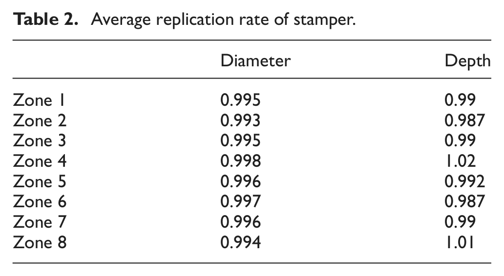
To observe the stamper after an etching process, five microstructures were selected randomly in each zone for diameter and depth measurement using a Nikon measuring microscope (MM-400/LM; Nikon, Japan) with noncontact Z-height measurement capability. The results in Table 2 show that the microstructures reached more than 99% and 98.7% of the target diameters and depths, respectively, in the etching process. Two microstructures in each zone were selected and measured with a three-dimensional (3D) surface roughness measurement ET-4000 (Kosaka, Japan) to evaluate the surface roughness. The surface roughness (Ra) ranging from 0.92 to 1.25 µm was measured, and the average roughness was found at 1.11 µm.
Average replication rate of stamper.
Imprinting pressure uniformity and the rigidity of the back pressure roller
In the preliminary test runs, it was found that the surfaces of the imprinted microlenses were not smooth, as shown in Figure 6(a). A pressure-sensitive film (Fuji Prescale Film, Japan) was placed in between the imprinting roller and substrate to investigate the imprinting pressure uniformity. The imprinting pressure did not distribute uniformly, as can be observed from the color distribution shown in Figure 6(a). The back pressure roller was made of polycarbonate (PC) material, while the imprinting roller was made of stainless steel, in this study. Errors inevitably arise in the making of both rollers. Together with the extra error from the assembling process, conformal contact between the stamper and the back pressure roller is not possible, which results in nonuniformity in the imprinting pressure. Yang et al. 30 used polydimethylsiloxane (PDMS) as the imprinting roller to smooth out the imprinting pressure in the nanoimprinting process. To improve the pressure uniformity in this R2R microfabrication process, a flexible foam rubber soft pad was wrapped around the back pressure roller. The original line contact between the imprinting roller and the substrate becomes a contact area with the add-on of a soft pad. As shown in the color distribution in Figure 6(b), the pressure uniformity was improved by the use of the extra soft pad, and the microlens imprint also showed great improvement (Figure 7).
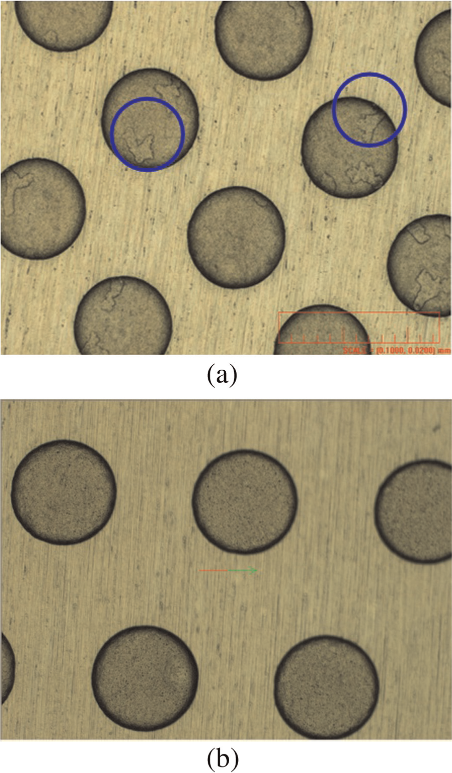
Lenses fabricated in the preliminary test runs: (a) without soft pad and (b) with soft pad.
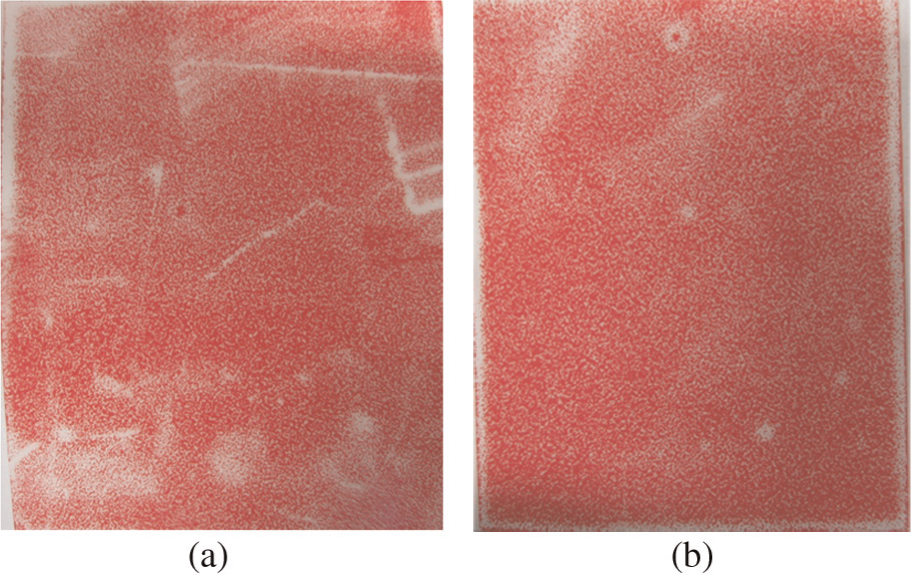
Imprinting pressure measurement with Fuji pressure-sensitive film: (a) without soft pad and (b) with soft pad.
Influence of imprinting pressure on lens replication rate
One important parameter affecting the replication rate of the lens is the imprinting pressure. It is also an indication of imprinting distance: the higher the imprinting pressure, the greater the imprinting distance and the more resin that is compressed to fill the cavity. When the pressure is too light, the UV resin can only partially fill the lens; when the pressure is too heavy, the imprinting pressure will make the stamper contact the substrate and damage it. 22 To investigate the effect on the replication rate of the lens diameter and height, imprinting pressures from 0.19 to 0.61 MPa were applied in the experiments, and the lenses fabricated were observed with a Nikon measuring microscope (MM-400/LM), a scanning electron microscope (SEM) (Hitachi S3000N, Japan), and a 3D confocal microscope (Nano Focus, Germany). Results show that the greater the imprinting pressure, the greater the replication in the applied pressure range. The average replication rate of the lens height, average lens height over the average depth of the microstructure on the stamper, was 91% when the imprinting pressure was 0.19 MPa, and it was higher than 97% when the pressure was 0.61 MPa.
Influence of substrate speed on lens replication rate
In the R2R process, the substrate speed also represents the UV exposure time. With a high substrate speed, under-exposure can happen since the UV resin does not have sufficient exposure time to UV light; thus, speed is an important factor in the R2R imprinting process. Speeds of 0.251–2.011 m/min were tried at the imprinting pressure of 0.61 MPa to study the filling effect caused by the substrate speed. The results showed that an average replication rate of 98% for the height could be achieved at a substrate speed of 0.251 m/min, but this rate decreased to 93% with a substrate speed of 2.011 m/min. The substrate speed did not have a significant influence on the lens diameter replication.
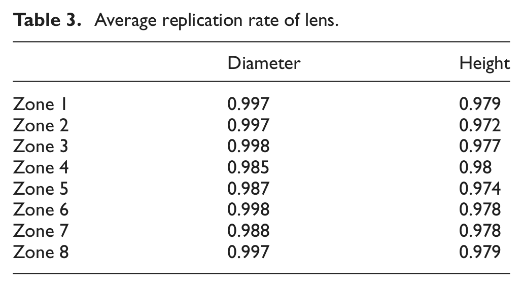
Among the imprinting pressure and substrate speed process windows, we found that an imprinting pressure of 0.61 MPa and speed of 0.251 m/min (1 r/min) give the best replication quality. Figure 8 shows the microscope pictures and the SEM pictures of the MLAs made in different zones with a pressure of 0.61 MPa and speed of 0.251 m/min. Figure 9 shows the 3D confocal microscope pictures of the smallest lens with a height of 14.674 µm and the largest lens with a height of 14.844 µm. The average replication rate for the height of the microlenses was around 97%, while the average replication rate for the diameters, the average lens diameter over the average diameter of the microstructure on the stamper, was about 98%, as shown in Table 3.
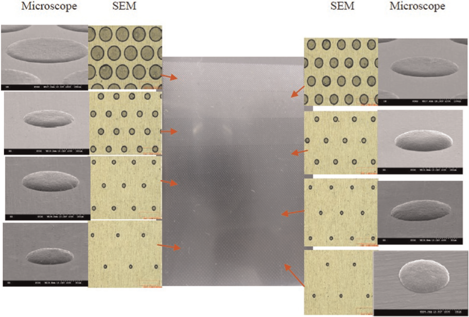
Picture of the MLA film and microscope and SEM images of the eight zones.
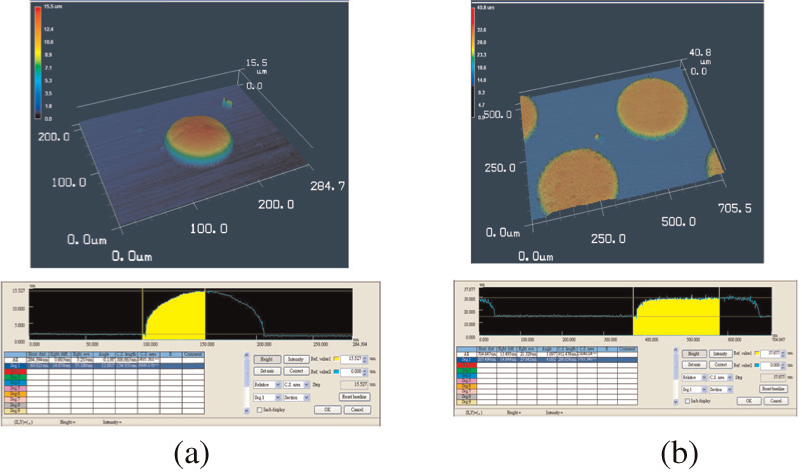
Three-dimensional confocal microscope pictures of the lenses: (a) the smallest lens (radius = 55 µm) and (b) the largest lens (radius = 247 µm).
Average replication rate of lens.
Influence of lens size on filling pattern
The SEM pictures of the lenses in Figure 8 and the 3D confocal microscope pictures in Figure 9 show single-peak and dual-peak filling patterns in different zones. Dual-peak filling occurred in zones 6–8, where the lens radii (sizes) were 117, 171, and 247 µm, respectively. Figure 10 shows more details of the cross-sectional views of the lenses formed in zones 6–8. The single-peak and dual-peak filling patterns are similar to those found by previous studies in embossing processes.28,31
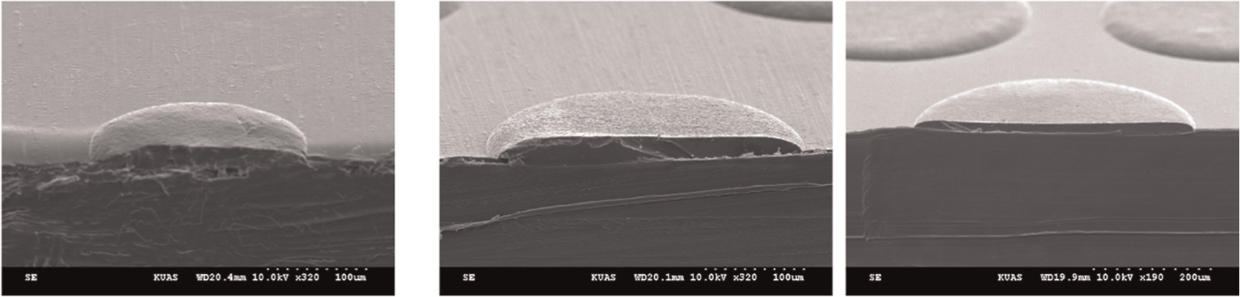
Cross-sectional views of lenses fabricated in zones 6–8.
Rowland et al. 28 showed that one of the factors affecting the filling pattern is the distribution of microstructures in the embossing process. To investigate the relationship between the filling pattern and the microstructure distribution in this R2R experiment, a cavity size factor (SF) is defined as R/(R+S), where R is the radius of the lens and S is the indenter width, as shown in Figure 1. The SFs for each zone are listed in Table 1. Dual-peak filling occurred in zones 6–8 where the SFs were greater than 0.349. These results were similar to those from the embossing process of Rowland et al., 28 which showed that a dual-filling pattern resulted when the SF was greater than 0.34.
There are two ways to make lenses with the R2R process depending on whether or not the lens surface makes contact with the cavity. With the contact R2R imprinting process, a complete filling of the stamp cavities and, consequently, a conformal molding of the stamp were possible when the imprinting pressure was great enough, as demonstrated in this study. A replication rate of more than 97% was achieved. However, it is more difficult to make lenses with good precision with dual-peak fillings, as happens with contactless R2R imprinting.
Surface morphology of the microlens
With the contact R2R imprinting process, the lens surface contacts the surface of the imprinting roller. It will duplicate the contour of the cavity, and it will affect the surface roughness of the lenses. To observe the surface morphology of the MLA, the surface roughness was measured by an atomic force microscope (AFM, Park Scientific Instruments, USA). Figure 11 shows the AFM image and roughness analysis of a randomly picked microlens from a single lens array. The average surface roughness (Sa) of a microlens was 67.697 nm over a 35 µm ×·35 µm area on the microlens top surface, which is much better than the average surface roughness of the cavities, 1.11 µm. With the contact R2R imprinting process, the lens surface contacted the surface of the cavity; however, the surface tension of the resin tries to pull the resins in the neighborhood and makes the surface roughness of the lens better than that of the cavity surface. In this study, the microstructures on the roller were made through the etching process, which resulted in a rougher surface. To further improve the lens roughness for the contact R2R imprint process, LIGA-like technology with a reflow process was applied in the making of the imprinting roller. With LIGA-like technology, an excellent surface roughness of only a few nanometers for the microstructures could be achieved. 32
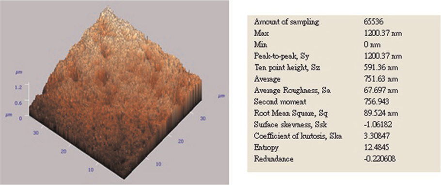
Surface roughness of the lens.
Optical effect of the MLA film
To evaluate the optical effects of the MLA film made in this experiment, the film was installed on one 2.5″ BLU, and its optical characteristics were measured with a Backlight Unit (BLU) Analyzer (BA664-BM7; Nieo E.O. Inc., Taiwan). As shown in Figure 12, an average luminance of 1460 cd/m2 and a uniformity of 56% were achieved with the MLA film developed in this study. Although there is a need for an optimal design of the MLA pattern to achieve better luminance uniformity, the R2R process shows great potential for fabricating flexible MLAs of different sizes for application to light guide film (LGF) for flexible display application.
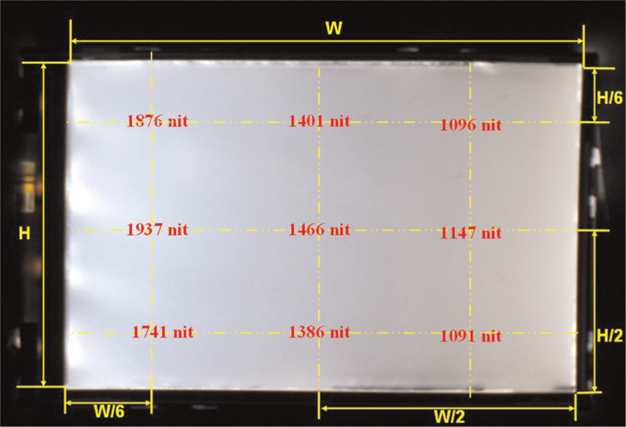
Picture of the MLA film optical quality observation.
Demolding
Demolding is the process that separates microstructures formed from the mold and is crucial in molding, imprinting, and R2R processes. Distortion and damage of the fabricated microstructures may occur during the demolding process as a result of friction, adhesion, and interlocking between the part and the mold surface. In our experiments, the MLA separated from the stamper successfully without applying a release agent to the stamper.
R2R evolved from the traditional imprinting process, but the demolding of the two processes is quite different. Imprinting processes demold vertically while R2R demolds with the parts and stamper moving in a circular motion. As Figure 13 shows, the relative movement of the part and the stamper can cause a collision and damage the part in an R2R process. More attention should be paid when designing the microstructures for an R2R process than for the imprinting process.
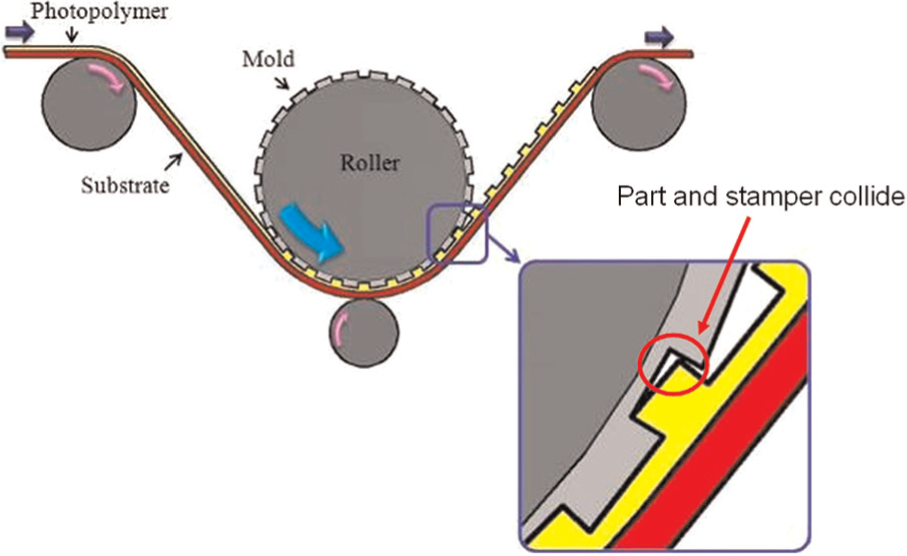
Schematic picture of collision in demolding process.
Conclusion
In this study, MLAs of different sizes were successfully fabricated on a flexible substrate using the R2R microfabrication process, thus demonstrating R2R’s potential as a rapid fabrication process with both low temperature and low imprinting pressure. Both single-peak and dual-peak filling patterns were found in the filling of the cavities. The dual-peak filling pattern occurred when the SF was greater than 0.349. Both imprinting pressure and substrate speed affected the replication rate of the height of the lens, but had little effect on that of the diameter. With enough imprinting pressure, the diameter and height replication rates were higher than 97% for both small and large sized lenses, which showed the potential of the R2R process in the fabrication of products with patterns of various sizes.
Footnotes
Funding
This study was supported by the National Science Council of Taiwan (under the grant of NSC 99-2221-E-151-050) and by the Chemical Research Laboratories of Industrial Technology Research Institute in Taiwan on fabrication of the stamper.