
Abstract
The hydraulic rolling shear whose hydraulic system is researched in this article is designed based on the theory of rolling shear. This article builds the transfer function of the unsymmetrical valve controlling unsymmetrical cylinder system and gets the expressions of the flow gain and the flow pressure coefficients and then compares them with the system controlled by symmetric valve. After the theoretical analysis, this article compares the control effects between the unsymmetrical valve and symmetric valve with the simulation software HYVOS. The simulation declares that when the unsymmetrical cylinder is controlled by the unsymmetrical valve, its control voltage is one-third of that controlled by the symmetric valve. Using unsymmetrical valve to control the unsymmetrical cylinder is perfect and meets the demands of the rolling shears as shown by the data collected from the field.
Introduction
The traditional rolling shears are the inclined blade shear and the pendulum shear. The inclined blade shear drives the up blade by synchronous cylinders, and the blade inclined in advance to shear the plates. When the overlap between upside and downside is large and uneven, the corner of the plates will collapse (shown in Figure 1(a)). The track of the pendulum hydraulic shear is around a center, and the surface of steel plates is always damaged, which makes the effect unsatisfactory. There is another kind of gear-rack hydraulic rolling shear, whose blade is a circular arc and moves along the guideway that is eccentric. 1 The gear rack driven by cylinders connects with the connecting rod by shaft that forms the eccentric structure (shown in Figure 1(b)). This structure has high production efficiency and good shearing quality. However, when it shears the wide plates, the cylinder’s piston rod is so long that the loads of the cylinders are unsymmetrical, the life of the seals is short, and the oil will penetrate. As for shearing the thick plates, the strength of all parts in the equipment should be strong, the weight is heavier, and the cost is much higher correspondingly.
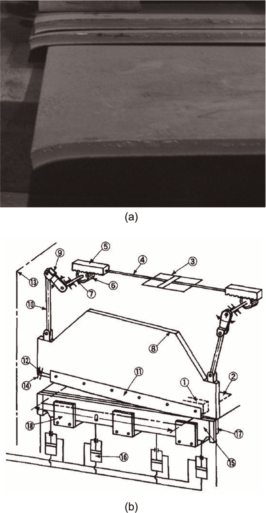
(a) Collapsed angle default by inclined angle shear and (b) structure of a prototype rolling cut shear (RCS) machine.
The new structure of the hydraulic rolling shear was designed for the HeBei WenFeng Steel Company 2800 mm medium plate production line. The hydraulic rolling shear uses the proportional servo valve and displacement sensor to control the position of the two cylinders in order to make the upper shear do the rolling motion. This is first time that the rolling shear is used in this way. 2 The features are shown in Figure 2(a). The two cylinders controlling the track of the blades lie in the horizontal type, and it is connected with the connecting rods and push rods with the pins, the other end of the push rods is connected with the rack, and the other end of the connecting rods is connected with the upper shear blade by pivots. The upper shear blade is connected with the rack by the guide rod. The advantages are the drive system is simple and reliable, the force is promoted, and the upper shear blade, which does rolling motion, improves the quality of the shearing area.
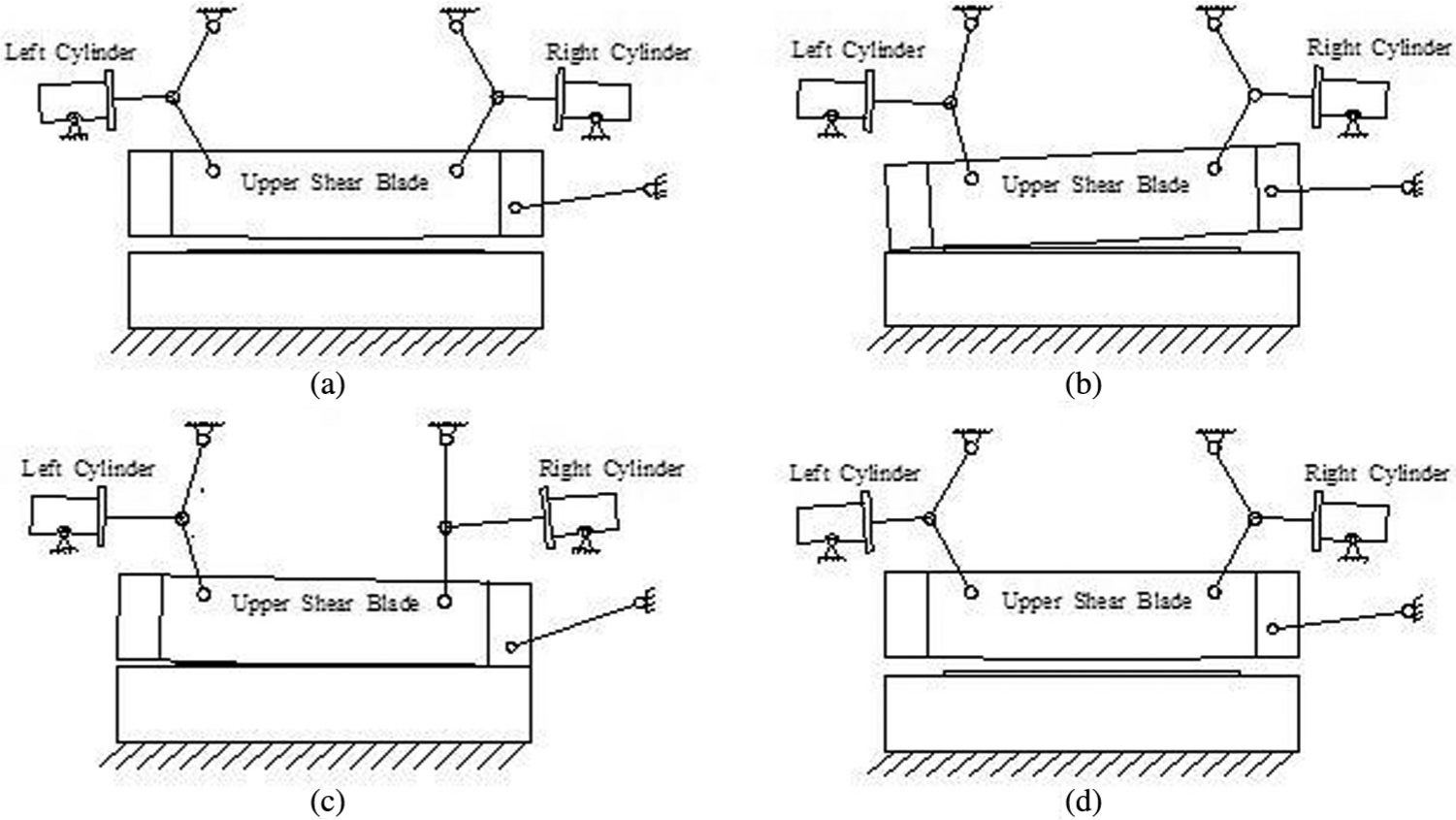
Map of the exhibition about the action of hydraulic rolling shear.
The track of the hydraulic rolling shear is similar to the traditional mechanical rolling shear.3,4 The upper blade is driven by the left cylinder and the right cylinder which moves as a certain curve.The process of shearing is shown in Figure 2. The beginning of shearing is shown in Figure 2(a). First, the left cylinder moves at a specific speed, and when it arrives at a certain place, the right cylinder begins to move (see Figure 2(b)). The left side of the upper blade descends in advance, and the right side follows after a certain phase until the upper blade meets the lower blade, and the upper blade does rolling motion to shear the plates (shown in Figure 2(c)). Finally, the rods of the two cylinders shrink to the original position (shown in Figure 2(d)). The equipment adopts a hydraulic drive to complete the shearing, whose structure is simple, optimizes the loading conditions, and improves the reliability; the operation and maintenance are easy and the cost is low. The equipment’s hydraulic servo system uses unsymmetrical valve to control the unsymmetrical cylinder, so the characteristics of this system are massive flow, fast speed, and high control precision. For analyzing this equipment, this article researches on the math model of valve controlling cylinder servo system.
Building the math model of the hydraulic system
The simplified model of hydraulic rolling shear servo system is shown in Figure 3; the model contains a proportion servo valve and an unsymmetrical cylinder. The flow equation of the valve, the cylinder’s flow continuity equation, and the cylinder and loads equilibrium equation are needed to build the math model of the hydraulic servo system.5–8
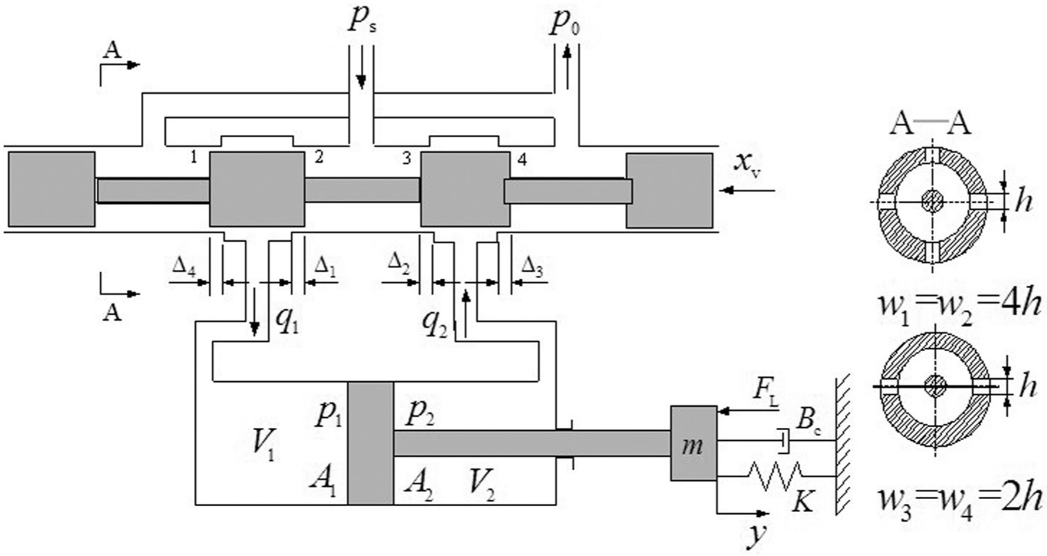
Principle of unsymmetrical cylinder controlled by servo valve.
Using the unsymmetrical proportion valve to control the unsymmetrical cylinder can decrease the changes of the loads and the pressure pulsation when the cylinder is reversing. The schematic diagram is shown in Figure 2.
The input and output area through the throttle windows of the unsymmetrical valve are in proportion

where W1 is the area grads of windows 1, 2; W2 is the area grads of windows 3, 4; and m is a constant that is smaller than 1. When m < 1, the valve is unsymmetrical; when m = 1, the valve is symmetric.
For the cylinder

where A1 is the effective action area of the rear cavity of the cylinder and A2 is the effective action area of the rod cavity of the cylinder.
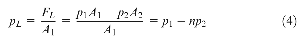
When the cylinder is stable, it satisfies the equilibrium equation

where p1 is the pressure of cylinder’s rear cavity (Pa), p2 is the pressure of cylinder’s rod cavity (Pa), and FL are the cylinder’s loads (N).
From equation (3), we get

where ps is the supply pressure and pL is the load pressure.
The output power of the cylinder is
Then the loads flow is

When the cylinder moves right, that is,
Linearizing at equilibrium points

where
The equilibrium equation of the cylinder and loads is

where mt is the mass piston and load converted to the piston, Bp is the viscous damping coefficient of piston and loads, K is the spring stiffness of the loads, and FL are the loads.
The flow continuity equation of the cylinder is


and we arrive at the equation
Using the Laplace transform of equations (7)–(9) and eliminating the intermediate variables, we can get the transfer function, whose inputs are the input displacement of spool and the loads
where
The proportional servo valve and the cylinder of the hydraulic rolling shear are unsymmetrical, the m of unsymmetrical proportional servo valve is 1/2 and the area ratio of the cylinder’s two cavities is 1/2, which matches the unsymmetrical valve. Put m = 1/2 and n = 1/2 in the flow gain coefficient and flow pressure coefficient and then compare them. The flow gain coefficient
The simulation research on the pressure changes of the hydraulic system
According to the simplified full hydraulic rolling shear’s hydraulic system scheme, the hydraulic system model (Figure 4) is built using HYVOS, setting each parameter based on the actual situation, while the displacement of the cylinder is given. The load of the cylinder is 3800 kg, the external load is 2.5 × 10 N, the area ratio of the cylinder’s two cavities is n = 1/2, the simulation time is 4 s, pressure is 270 bar, and the proportional servo valve is 4WRTE series unsymmetrical valve of Rexroth. The system’s dynamic response is simulated with symmetric and unsymmetrical valves.
The model of the hydraulic system.
The block diagram of the control system is shown below:
The step displacement of the cylinder is 1 mm; from Figure 5, which is the step response curve of unsymmetrical valve controlling the unsymmetrical cylinder, it can be seen that the rising time is about 40 ms and the maximum voltage to control the valve core is 1 V. The maximum stroke of the valve core is 7% of the total. When reaching the certain place, the control voltage will be low and the displacement control accuracy will be high. From Figure 6, it can be seen that the rising time is 50 ms and the maximum voltage to control the main valve core is 3.5 V, the stroke of the valve core is 25% of the total, when reaching the certain place, the control voltage is high, and the cylinder’s displacement is violent vibration. Simulating the step response curve of the cylinder controlled by the unsymmetrical and symmetric valves shows that as the flow gain
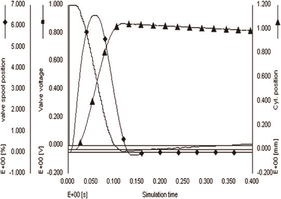
Step response curve of unsymmetrical cylinder controlled by unsymmetrical valve.
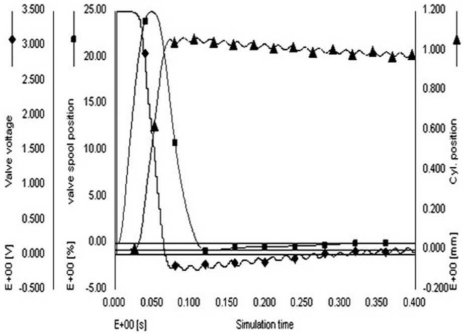
Step response curve of unsymmetrical cylinder controlled by symmetrical valve.
Experimental studies
The full hydraulic rolling shear was made for a steel plate. As the main cylinder’s speed is fast, position control precision is high, and as the two cylinders’ positions are associated, accurate position control should be considered. The hydraulic system uses the unsymmetrical valve to control the unsymmetrical cylinder and the main valve is the 4WRTE proportional servo valve produced by REXROTH, which is also unsymmetrical. Considered economic issues, the symmetric valve is not setup to make contrast, the cylinder’s two cavities area ratio is n = 1/2, the pressure is detected by pressure sensor and the displacement is detected by displacement sensor. The equipment is shown in Figure 7(a). Figure 7(b) shows the unsymmetrical valve controlling unsymmetrical cylinder system.
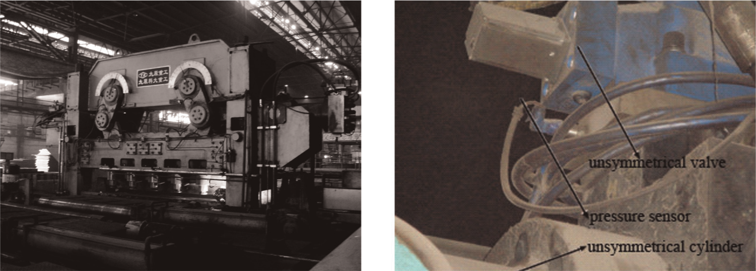
Experimental scenario: (a) experimental setup and (b) outside view of the unsymmetrical valve controlling unsymmetrical cylinder system.
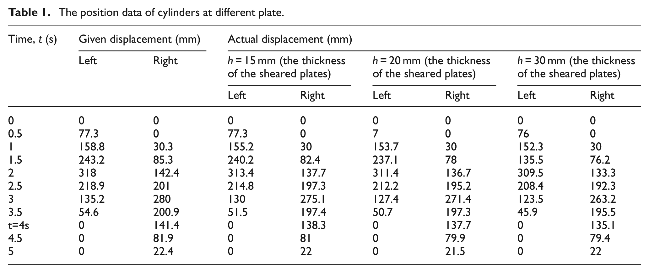
The experiments are made on different thicknesses of the steel plates, collecting the cylinder’s actual position and pressure to analyze the error between the actual data and the given data with different loads.
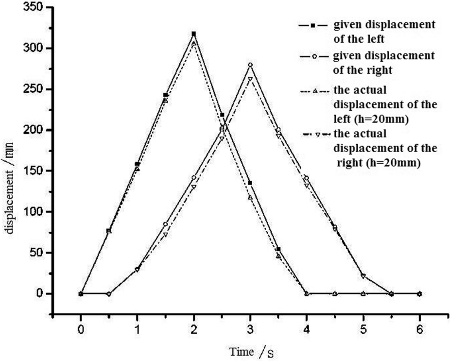
Compare the actual displacement and the given displacement at the same time (as shown in Table 1). Then, draw the error curve of the left cylinder; from Figure 8, it can be seen that with increasing thickness of the sheared steel plates, the pressure and displacement are high. When the steel plates are 15 mm, the left cylinder’s position error is 2.3%–4% and the right is 1.3%–5.7%. When the plates are 20 mm, the left is 2.5%–5.8% and the right is 4%–8.5%. When the plates are 30 mm, the left is 2.7%–7.9% and the right is 6.4%–10.7%. The bigger load is, the bigger position error is, the hydraulic rolling shear’s upper and lower shears’ overlap error is 2%–6%, the cylinders position error has nothing to do with the precision of the route of the rolling shear.
The position data of cylinders at different plate.
The position data of cylinders at different plate.
The reason why the position error is increasing is that when the sheared steel plates are thicker, the loads on cylinders are bigger accordingly, and the cylinder’s position error is bigger. As long as the cylinders reach a certain position, they will get back at a speed of 200 mm/s. At this time, the hydraulic shock in the cylinder is so big that the cylinder’s position error is big.
When debugging the hydraulic rolling shear, the proportion gain parameter is critical to the system’s stability, the increase of the gain can decrease the steady-state error, while, with the gain increasing, the hydraulic system will be concussion and overshoot.10,11 When P = 2, the cylinders’ position error is the smallest, whereas when they get back, they are badly overshot, and the pipes are shaken seriously. At last, considering the safety issue, decreased the parameter P, and deteriorated the accuracy. 12
Summary
This article designs a full hydraulic rolling shear using the hydraulic cylinders to drive the upper shear blade based on the rolling shear theory. Building the math model of the unsymmetrical valve controlling the unsymmetrical cylinder implies the reliable parameters of the displacement and load for the hydraulic control system. The theory and the field data both indicate that the hydraulic servo control system can satisfy the characteristics of the hydraulic rolling shear’s shearing track. The conclusions by comparison are as follows:
Controlling the relative position of the two cylinders makes the upper blade go into rolling motion. Compared with the other hydraulic shears, the hydraulic rolling shear is easier to repair, the structure is simpler, the cost is lower, the track of shearing is more accurate, and the sheared plates have no sunken corners.
The flow gain coefficient
When debugging the proportional–integral–derivative (PID) parameters, the control precession should be high and the pressure fluctuation should be small in order to ensure that the equipment can run safely and is reliable.
Footnotes
Funding
This article was supported by 973 Project (2011CB612204; 2012BC722801), National Nature Science Foundation of China (51105264, 51104104), and University students’ innovative project (120164042). The initial funding of doctor research of Taiyuan University of Science and Technology (20122047).