
Abstract
According to the theory of rolling shear, a new composite connecting rod mechanism driven by cylinders is invented. The shearing mechanism moving curves and equilibrium equations are calculated to build the transfer function of unsymmetrical valve controlling unsymmetrical cylinder. The key points of the track of shearing mechanism, the pressure and position of cylinders are analysed when the rolling shear shearing the plates in different thickness by simulation. The data from the plant suggest that the new mechanism can meet the demands. Using unsymmetrical valve to control the unsymmetrical cylinder can achieve the position control for the system with high speed, massive flow and heavy load and can reduce the reversing impact.
Introduction
For complex structure, heavy weight and much money for maintenance of the crankshaft connecting rod rolling shear are serious problems, so the new PR-8R-PRII composite connecting rod rolling shear driven by hydraulic cylinders is invented, which was made for 3500-mm medium plate production line and got six patents in China. The new shear cut off the plates rollingly using proportional-servo valve and position sensor to control the track of the two cylinders. By this way, the motors, the reducers, the crankshafts and the connecting rods are saved, and the mechanism is simplified; the transmission system is simple and reliable, and it makes the power bigger; the quality of shearing section is better than before.
Symposys of the principle of composite connecting rod rolling shear
Principle of composite connecting rod rolling shear
The rolling shear mechanism is composed of the connecting rods AE, BF, EC, FD, guide bar HG, piston rods KE, JF, upper blade holder CDG and hydraulic cylinders. The composite connecting rod AEC-BFD-CDG-GH is driven by hydraulic cylinders, so the upper blade can do the composite movement combining swing and rolling by changing the order and the speed of the two cylinders.1,2 The PR-8R-PR connecting rod, a composite connecting mechanism with 2 degrees of freedom, is composed of 12 revolute joints R and 2 shifting pairs P.
Build the motion equations of composite connecting rod mechanism
Build the nonlinear position-loop equations by the global coordinate of hinged joints3,4
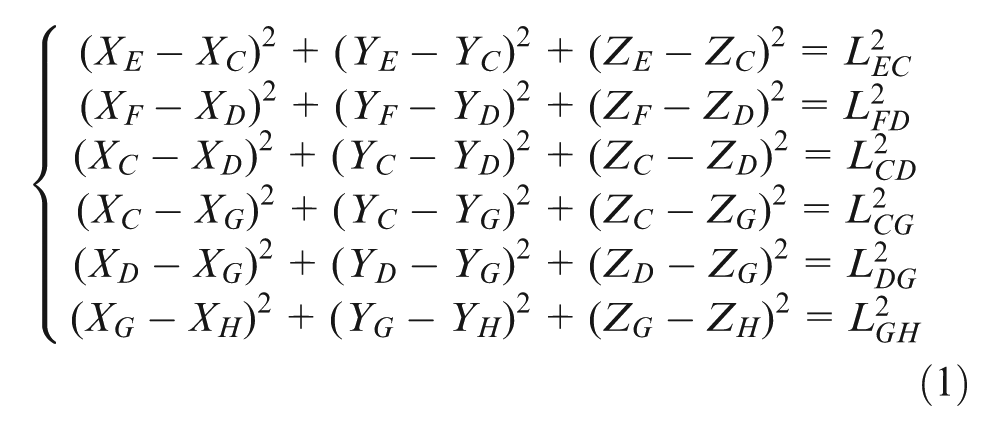
where
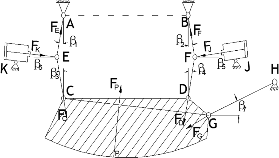
Mechanism of hydraulic rolling shear.
Build the moment equilibrium equations of composite connecting shearing mechanism
When shearing, the cylinder on the side of K moves first, and the plate breaks from the side of K, with the position of the notch moving, the position of shearing force
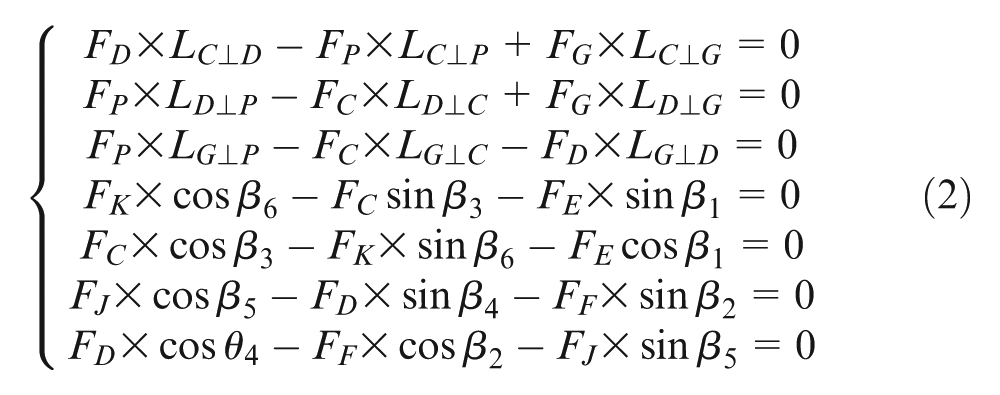
where:
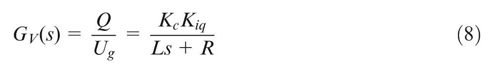
Build shearing mechanism hydraulic control system model
This hydraulic servo system uses unsymmetrical valve to control unsymmetrical cylinder. The schematic diagram is shown in Figure 2.
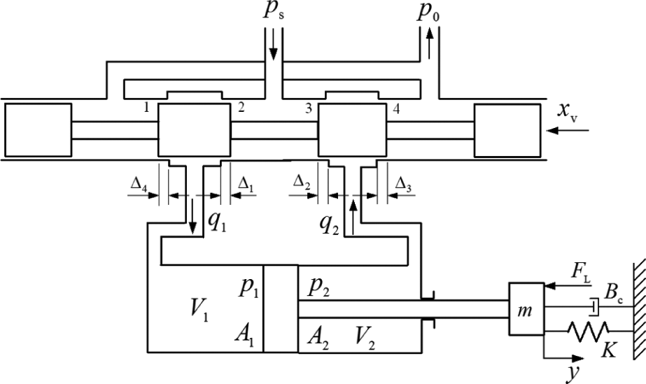
Principle of unsymmetrical cylinder controlled by servo valve.
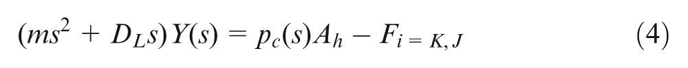
Load equilibriums of hydraulic cylinder
According to the characteristics of fluid and loads, load equations of hydraulic cylinder are built as follows

where m is the mass of motion parts,
Translating this equation by Laplace
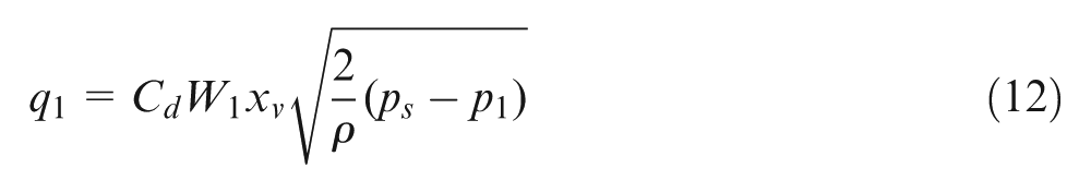
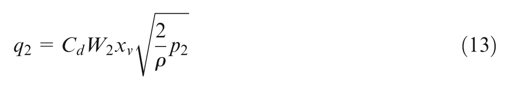
In order to reduce the pressure loss and improve dynamic performance, the high-frequency response valve is installed on the cylinder; the temperature of oil and the bulk modulus are constants.5–7 The simplified flow continuity equation is as follows
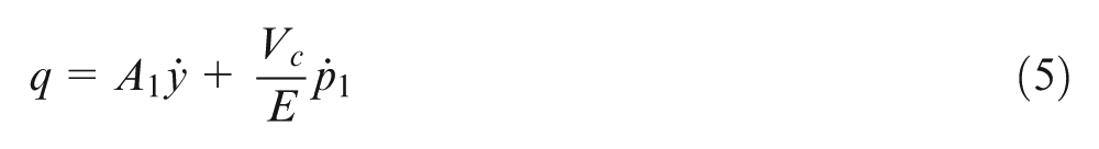
where q is the fluid flow into cylinder,
Translating the equation by Laplace
High-frequency valve and position sensor transfer functions
According to the conditions, a high-frequency valve is used; for
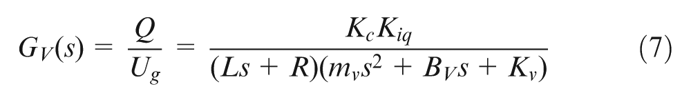
where
This equation shows that the transfer equation of high-frequency valve consists of a first-order process and a second-order process. For the equivalent mass of armature and equivalent stiffness are small, the second-order process is ellipsis, but the first-order process caused by proportional electromagnet coil inductance cannot be ignored, so the transfer function of high-frequency valve becomes as follow 8
The position sensor produced by the USA Mechanical Testing and Simulation (MTS) is interior and its frequency response is higher than required of the whole system, so its transfer function is proportional 9

where
Build the hydraulic control system block diagram (shown in Figure 3) based on all the transfer functions above. With the change in shearing force and the position of connecting rods, the pressure of cylinder’s two cavities will change. By this, the new moment balance can be built. Data of piston’s position collected from sensor are compared with the solutions of function (1), then the voltage of the high-frequency valve is adjusted, the flow will change correspondingly, and the position of the cylinder will track the curve calculated; the upper blade can move rollingly.
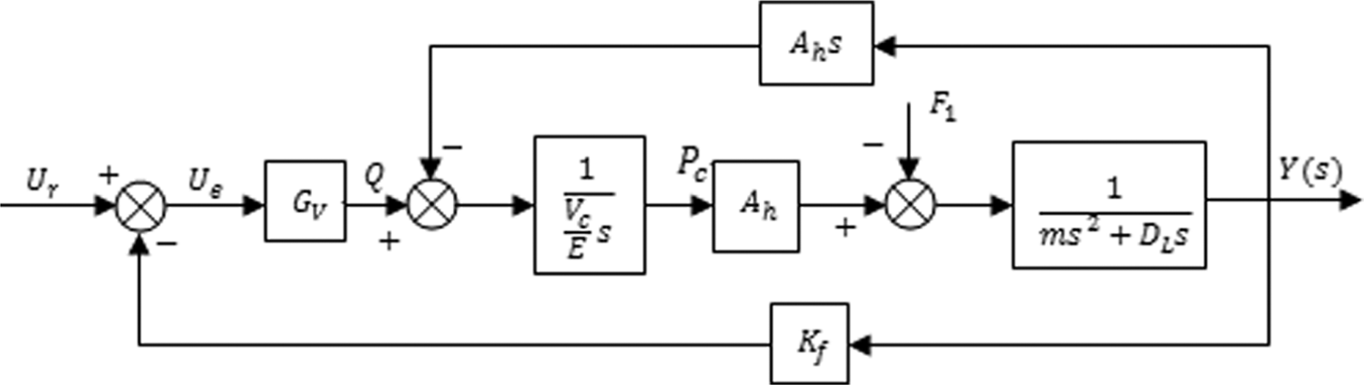
Circuit of hydraulic system.
Reversing impact of cylinder
The cylinder moves to the destination and gets back at fast speed at 120 mm/s, so the reversing impact is too big, while using unsymmetrical valve to control the unsymmetrical cylinder can reduce it. The schematic diagram is shown in Figure 2.10–13 Area grads of in- and out-throttle windows of unsymmetrical valve are proportionate 14
where
For the cylinder
where
When
The pressures of two cavities of cylinder are as follows
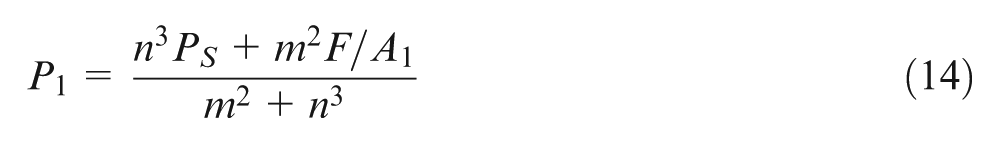
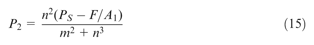
When
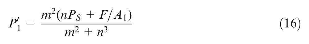
where
Simulations and testing
According to the process parameters of 3500-mm hydraulic rolling shear, make the kinematics simulation by the software Simulink and get the position curves of hinge joints C, D and the cylinder (shown in Figures 4 and 5). Set load mass as 4200 kg, load force as 5.12 × 10⁶, the area ratio of cylinder’s two cavities as 1/2, simulation time as 4 s, the system pressure as 35 MPa and high-frequency valve as 4WRTE produced by Rexroth, which is unsymmetrical.
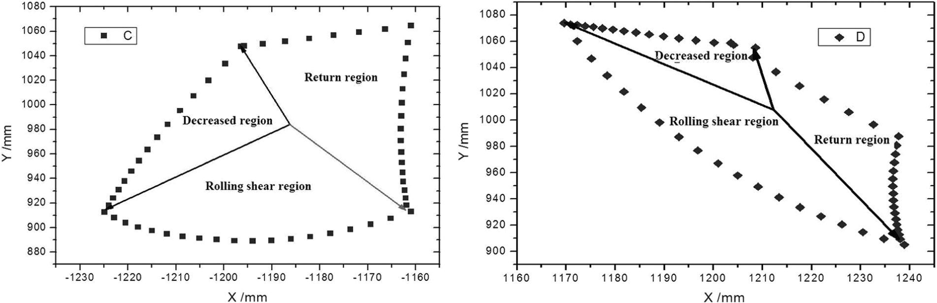
Kinematic paths of points C and D.
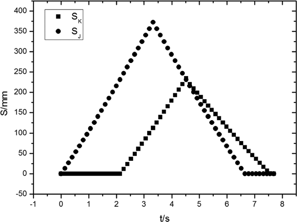
Curve of given position.
The simulation curve (in Figure 6) suggests that the reversing impact is small; when the cylinder is reversing, the pressure of blind end of the cylinder is from 19.62 to 19.87 MPa,
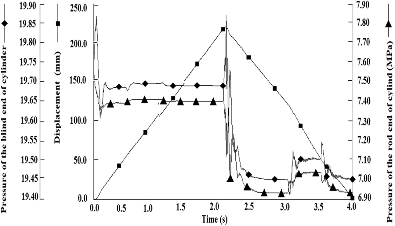
Reversing impact of unsymmetrical valve controlling cylinder.
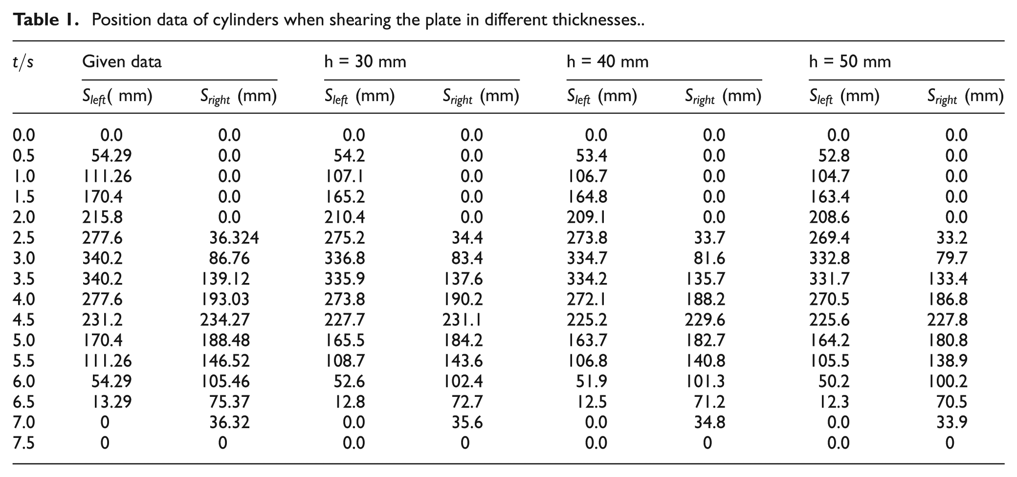
Install the pressure sensors and position sensors on the cylinders to get the data for analysis of how the cylinder position and pressure change with the different loads. Table 1 shows the calculated data and the actual data, then, makes the curves based on them. Figure 7 suggests that with the increase in thickness, the error of pressure and position becomes bigger. When the thickness of plate
Position data of cylinders when shearing the plate in different thicknesses.
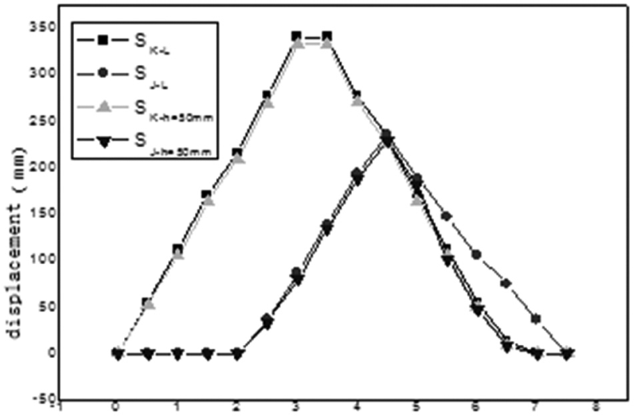
Position data of cylinders at different plates.
The reason for why the error is bigger with the thickness of plate is that when the cylinder speed is fast, the orifice area of the valve is big, while the frequency response is too low to compensate the cylinder’s position error.
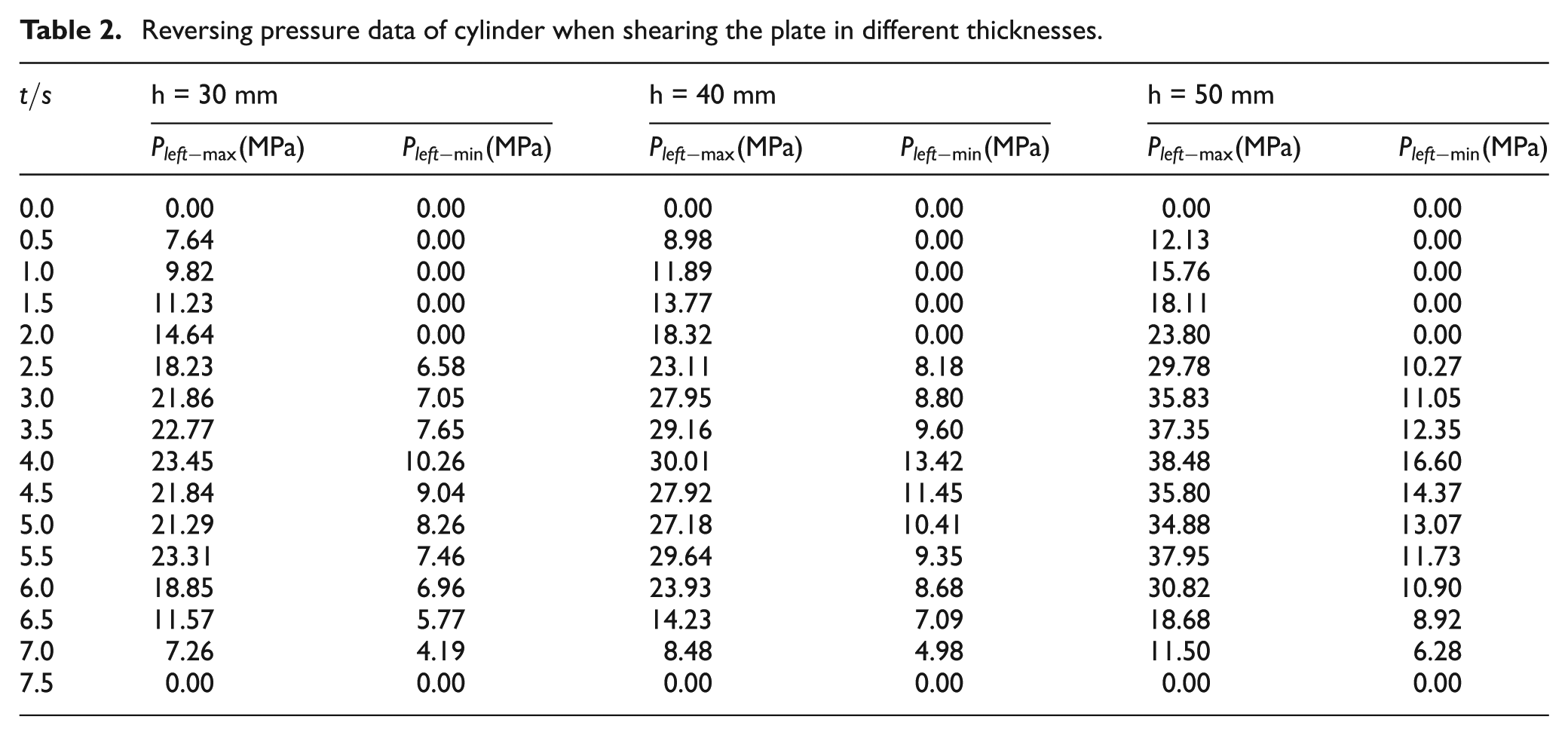
Table 2 shows the pressure of cylinder’s two cavities when the sheared plate is 30 mm thick, the pressure impact of the blind end of the cylinder is 1.6 MPa and the pressure impact of the rod end of the cylinder is 3.2 MPa; when the sheared plate is 40 mm thick, the blind end is 2.15 MPa and the rod end is 3.64 MPa. When the sheared plate is 50 mm thick, the blind end is 2.68 MPa and the rod end is 4.25 MPa; the thicker the sheared plate, the bigger the pressure impact. The reason for this is when the cylinder gets the maximum displacement, the steel plate is sheared off and the load disappears, and the force balance of the cylinder is broken, so the pressure is higher suddenly to balance load. Figure 8 shows the quality of the cross section of sheared plate; the high quality also proves that it is valid to use unsymmetrical valve to control the unsymmetrical cylinder.
Reversing pressure data of cylinder when shearing the plate in different thicknesses.
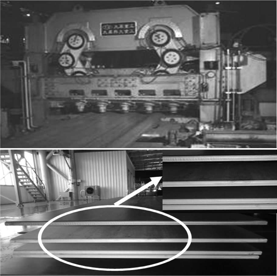
Full hydraulic rolling shear and shear plate section.
Summary
This article puts forward a new composite connected rod rolling shear, whose structure is simple, stable and reliable, and the quality of cross section is better. The following conclusions are drawn:
Calculate the shearing mechanism moving curves and the data of cylinder position and pressure by building its motion equations and equilibrium equations. All these lay the foundation for simulating and verifying that the mechanism is applicability theoretically.
Using unsymmetrical valve to control the unsymmetrical cylinder can reduce the impact when the cylinder is reversing. Adjust the parameters of proportional–integral–derivative (PID) in order to pursue the high control precision and low reversing impact.
The reason for why the position error is bigger is that when high-frequency valve orifice area is big, its frequency response is low. The moment when cylinder begins to move, its accelerated speed is fast and needs massive flow, so the high-frequency valve orifice area is too big to compensate the position error of the cylinder, and with the time going on, the error is bigger.
Footnotes
Appendix 1
Declaration of Conflicting Interests
The author(s) declared no potential conflicts of interest with respect to the research, authorship, and/or publication of this article.
Funding
The author(s) disclosed receipt of the following financial support for the research, authorship, and/or publication of this article: This article was supported by National 973 Project (2011CB612204; 2012BC722801), the initial funding of doctor research of Taiyuan University of Science and Technology (20122047), National Natural Science Foundation of China (51375325), Provincial Fund for Young Scholars (2013021019-2) and Technology Innovation Project for Postgraduate of Taiyuan University of Science and Technology (20134023).