
Abstract
This article deals with the analysis of tolerances for an assembly that is bound to meet some functional requirements over a specified range of operating parameters (e.g. temperature, pressure and speed). These can influence part dimensions due to physical effects such as thermal expansion, deformation and wear. When these influences are added to manufacturing errors, unacceptable values of functional requirements can occur under critical conditions on operating parameters. To avoid this, a designer should be able to readily evaluate the operating window allowed to the assembly by a given set of tolerance specifications. A method is proposed to help this task on the assumption that requirements are verified through worst-case linear chains of dimensional tolerances.
Introduction
Assemblies are subject to functional requirements that can be affected by the stack up of manufacturing errors. Well-known examples are clearances and fits to be controlled for the purpose of sliding, bearing, sealing or other mechanical functions. Each applicable requirement must be identified and related to a set of dimensions and geometric characteristics of individual parts. Tolerances are then specified on these design variables in order to control deviations from nominal values of requirements. Tolerance analysis verifies that deviations on requirements have acceptable values under a set of specified dimensional and geometric tolerances. For this purpose, a stack up equation (tolerance chain) is identified for each requirement, although different algebraic procedures may be needed depending on the complexity of the assembly.
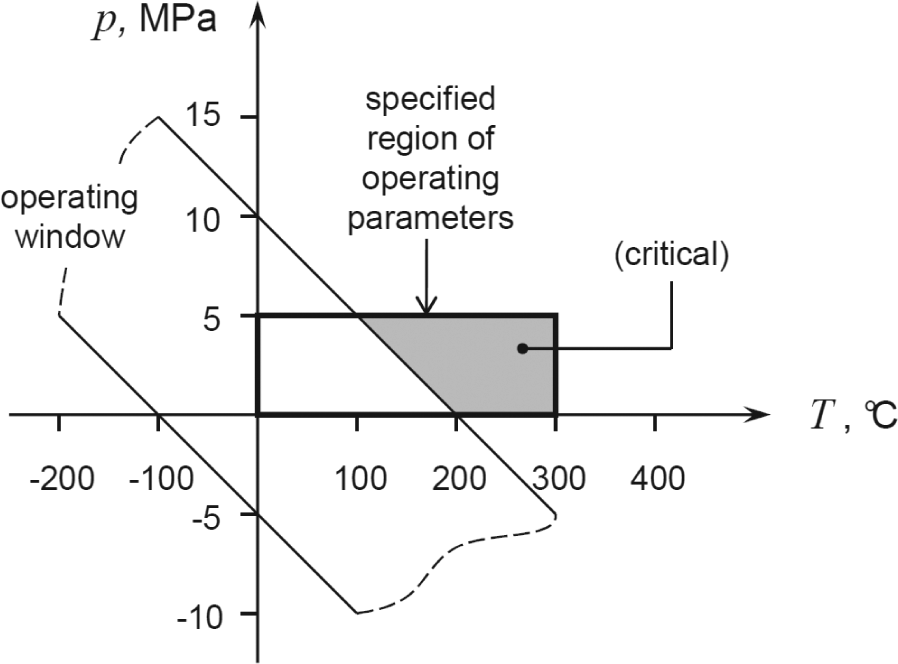
Tolerance analysis has to consider the full range of operating parameters specified for the assembly. They could have effects on part geometry and influence stack up equations. The most obvious example is temperature, which can cause differential expansion of parts. Force-induced deformation is likely to depend on parameters such as the pressure of a fluid or the speed and acceleration of some mechanism. Even time and environmental conditions can be considered as operating parameters as they can alter part dimensions due to wear and degradation. In these cases, a designer should be able to evaluate the operating window of the assembly, that is, the region in the domain of operating parameters that yields acceptable values of all functional requirements. As illustrated in Figure 1, when operating parameters are out of the operating window, there is some probability that at least a functional requirement violates its assembly tolerance. When this happens, part tolerances should be reallocated, so that the operating window could cover the whole specified region of operating parameters.
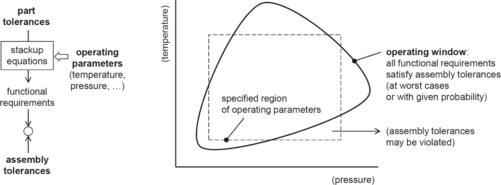
The operating window in a tolerance analysis problem.
In most cases, the effect of a single operating parameter on one or more tolerance chains is easily evaluated. For an assembly that works at variable temperatures, thermal expansions can be added to part dimensions as a function of temperature. This allows us to readily identify the operating window of the assembly from a given set of tolerance specifications. For example, the three parts in Figure 2 have the following dimensions in millimeter, which depend on a temperature parameter T in degree Celsius (defined as the operating temperature minus 20 °C)
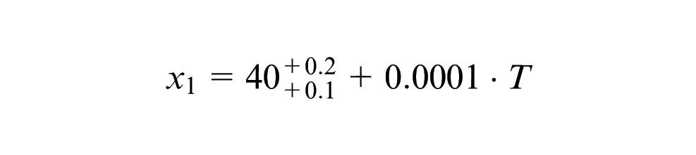
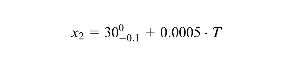
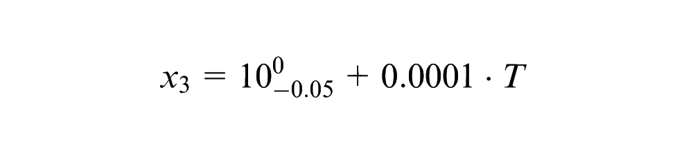
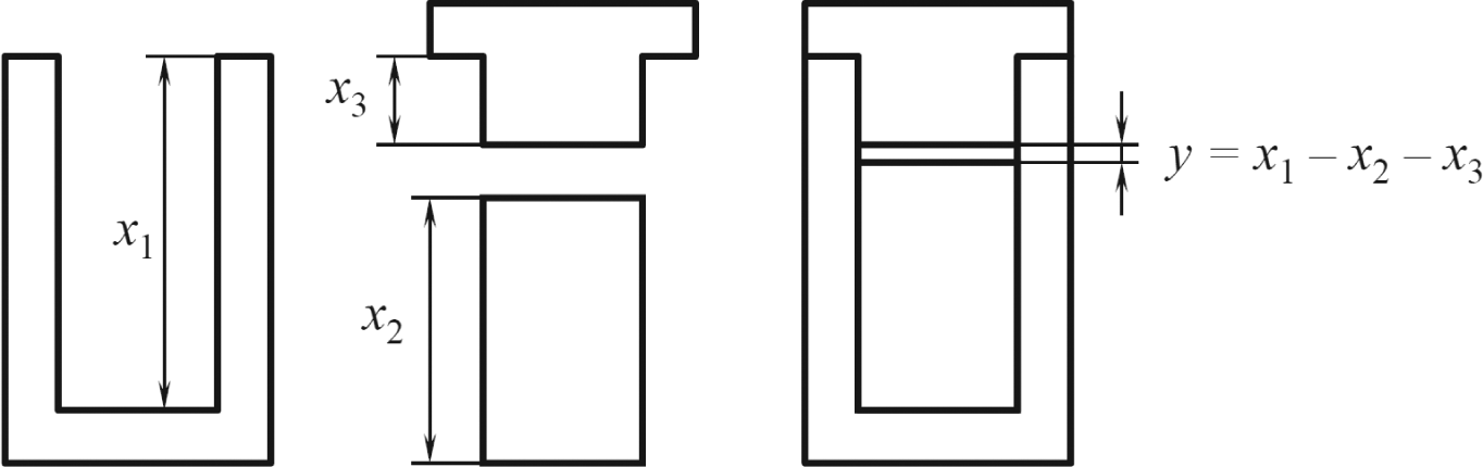
Conceptual example.
The single functional requirement identified for the assembly is distance y, which is bound to vary in the range from 0 to 0.4 mm. Such requirement is actually satisfied at T = 0 °C, as it can be calculated from tolerance specifications
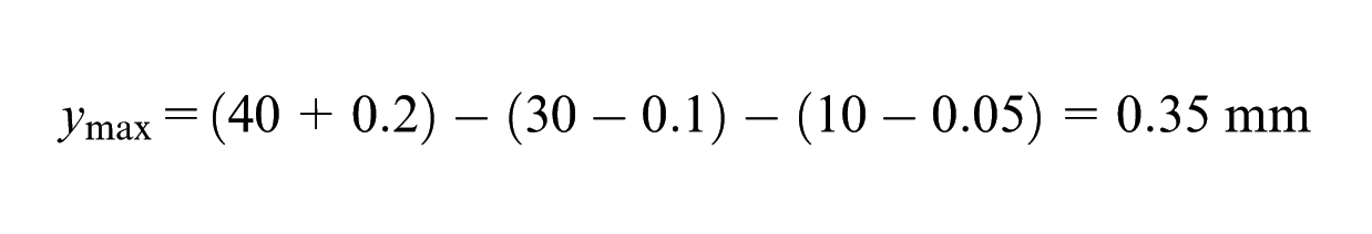
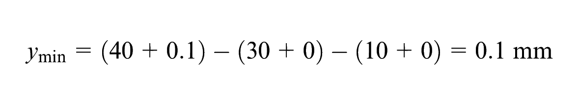
The part with height x2 expands more than the other ones, thus making the clearance decrease at increasing temperature. This can bring about two undesired consequences: (a) interference (y < 0) at high temperatures and (b) excessive clearance (y > 0.4) at low temperatures. It can be verified that the above critical conditions occur at T > 200 °C and T < −100 °C, respectively. If the range specified for T is between 0 °C and 300 °C, excessive clearance will never be a problem, while interference will occur for a considerably wide range of temperatures.
Detecting similar conditions may be less trivial when considering multiple operating parameters and functional requirements. In the general case, the operating window is a region with a complex-shaped boundary in a multidimensional space. Its identification can be tedious and error prone for a designer, which is thus forced to separately check a possibly large sample of operating conditions. This article proposes an analytic procedure developed in order to allow an easy calculation of the operating window from given tolerance specifications. The problem is approached on the restrictive assumptions that assembly requirements are modeled as linear chains of dimensional tolerances with worst-case stack up. Operating parameters are assumed to have equal linear effects on the two tolerance limits on each dimension.
The remainder of this article is organized as follows. Related literature is first reviewed, and a formal definition of the problem is given. The proposed method is then described through some steps involving an incremental release of assumptions. The application of the method is illustrated on an example and critically discussed before some conclusions are eventually summed up.
Background
The present work is an attempt to extend and generalize the solution to a common design problem, that is, the analysis of dimensional tolerances in the presence of thermal expansion. Finding the operating window with respect to one or more tolerance chains is a relatively easy task. Some research attention has been given to the related problem of tolerance synthesis, which consists in setting nominal dimensions and tolerances so as to minimize cost and satisfy constraints on functional requirements, considering the temperature range in which the assembly will operate. Jeang et al. 1 adopt a cost function that includes the quality loss due to deviations from nominal values of functional requirements, defined as in Taguchi methods. Monte Carlo simulations are used to evaluate cost on a set of combinations among design variables: this is probably not required for linear tolerance chains but would allow to treat cases where functional equations are nonlinear or even unknown by means of experimental testing or complex simulation models.
The impact of temperature is more complex on the analysis of geometric tolerances, which must take into account additional effects such as thermal distortions and possible loss of contact among parts. These are especially difficult to evaluate on overconstrained assemblies, where deformations of adjacent parts interact with one another. In these cases, stack up equations based on purely geometric reasoning are not enough and must be integrated with an analytic or simulation model specifically developed for the assembly to be analyzed. Pierre et al. 2 use thermal finite element method (FEM) simulation to calculate relative displacements among parts due to temperature, which are then included as additional terms in an analysis model based on the small displacement torsor approach. Benichou and Anselmetti 3 adopt a similar approach with a different analysis model based on implicit equations that describe the effect of tolerances on functional requirements; several methods are proposed to evaluate the effect of thermal expansions depending on problem complexity, including FEM simulation in the presence of thermal cycles or temperature gradients. The method of Ballu et al. 4 analyzes the propagation of geometric errors on overconstrained assemblies and could also be useful to treat the effect of thermal expansion, although it is not explicitly considered by the authors. With an emphasis to the verification of assembly function, Bing and Ye 5 evaluate the variation of the dynamic response of a valve for steam turbines under changes of operating temperature; the analytic approach common to multibody problems is combined with equations that describe the effect of heat transfer on mechanism geometry.
As demonstrated by Baker and Steinrock, 6 a wider set of operating parameters can be included in computer-aided tolerance analysis to model thermal, structural and wear effects. The effects of operating conditions on tolerance chains can be especially severe on compliant assemblies, which have been widely studied from the viewpoint of tolerance analysis. Methods proposed in this context (e.g. Cid et al. 7 with deterministic approach and Stewart 8 with statistical approach) use FEM simulations to evaluate deformation of parts and could be adapted to problems involving variable temperature, pressure or other parameters with effect on part geometry. Mazur et al. 9 point out that the integration of a simulator within a computer-aided tolerancing tool can significantly improve the analysis of functional requirements in the presence of force-induced deformation. The coupling between structural and tolerance analyses can lead to difficulties due to the need of design iterations; to avoid this issue, Walter et al. 10 propose a reverse design procedure that uses structural optimization of parts as a means of ensuring the fulfillment of predefined limits on deformations. For more complex problems involving inertia and vibration on mechanisms, Walter and Wartzack 11 and Walter et al. 12 use empirical models of deformations derived from multibody dynamics simulation.
The importance of simulating functional requirements in the presence of thermomechanical disturbances has also been pointed out in the study of assemblies with little compliance and high precision, whose functions can be strongly affected by clearances and distortions in operation; analysis methods in this context are proposed by Kimura et al. 13 and Stuppy and Meerkamm. 14 The problem of sensitivity to disturbances (or robustness) is investigated in several articles by Söderberg et al.,15–18 which also discuss how an assembly can be designed with geometric positioning schemes that attenuate the stack up of deviations (concept referred to as geometric stability).
This article considers the operating window as the allowable region in the space of parameters for the correct function of an assembly; since these parameters are imposed by operating conditions, the interest of a designer is focused on the boundary of the allowable region. The concept of operating window is also used in the different context of design of experiments; specifically, it is helpful to treat parameter design problems, where one or more control factors of a system must be set in order to avoid failures. As the probability of each failure mode depends on control factors and disturbances, the design problem could be faced through an experimental plan that measures the occurrence of failures on a set of combinations among control factors. As it has been pointed out, a more cost-effective approach consists in defining one or more metrics that can easily be evaluated for each combination of variables (operating window factors) and in evaluating the range of values they take in the absence of failures. In this case, the importance does not lie on the boundary of the operating window but on the chance of identifying a point in the center of the region; this actually corresponds to a setting of design variables that are likely to be relatively insensitive to system disturbances. The approach was introduced several decades ago at Xerox company (see Clausing 19 for a retrospective account) and later integrated in the Taguchi robust design methodology; Joseph and Wu 20 propose a statistical procedure for the construction of the operating window from experimental plans.
Problem definition
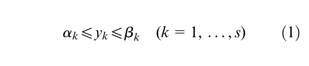
Let the following conditions be given on the functional requirements y1, y2, …, ys of an assembly
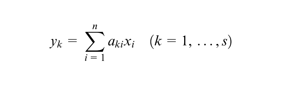
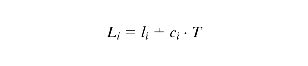
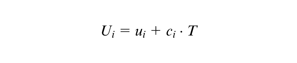
Requirements depend on a set of functional dimensions x1, x2, …, xn of parts by the following linear tolerance chains
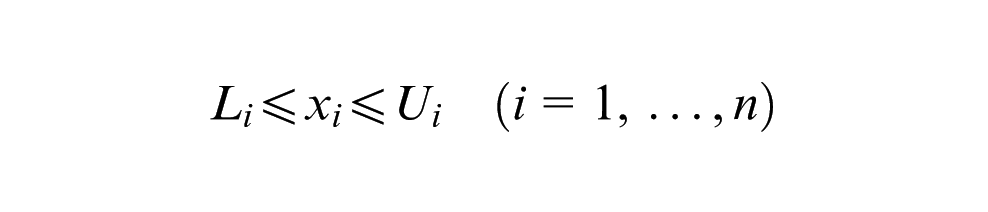
Tolerance specifications impose the following lower and upper limits on dimensions
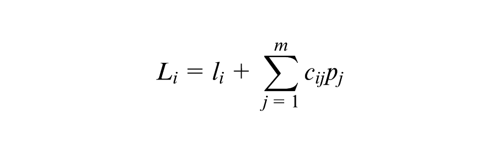
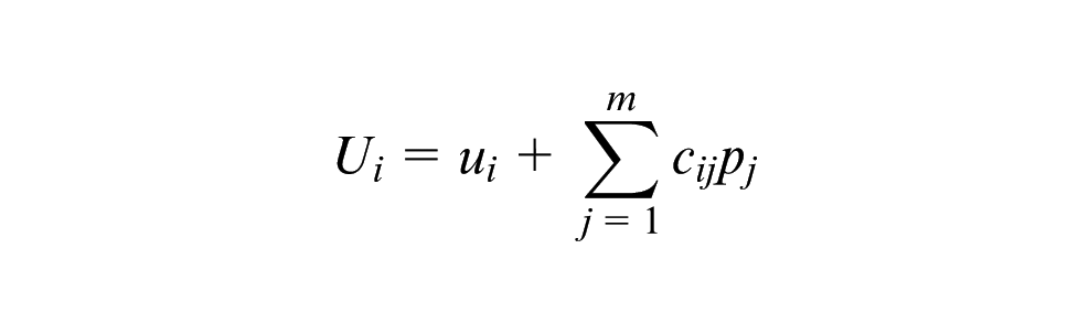
each having an equal linear dependence on operating parameters p1, p2, …, pm
The problem consists in finding the conditions on parameters pj under which the constraints in equation (1) are satisfied. Each requirement yk involves two inequalities of the following type
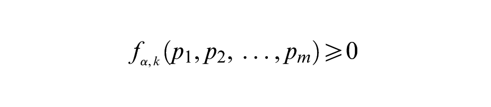
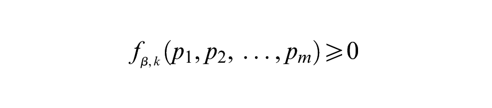
It is easily verified that the unknown functions fα,k and fβ,k are linear in parameters pj. For example, in condition yk≥αk, the minimum value of yk can be expressed as
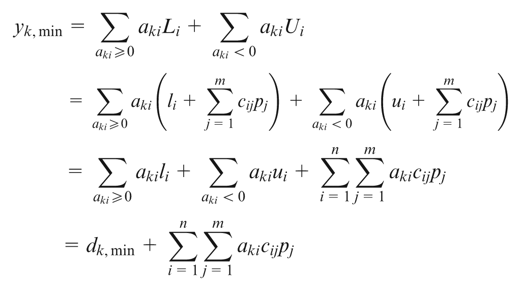
It is thus proved that fα,k = yk,min, where αk is a linear function. A similar proof applies to function fβ,k derived from the condition yk≤βk.
Proposed solution
The procedure for calculating the allowable region in the domain of parameters will be first described on the simple cases of a single tolerance chain depending on either one or two parameters. Generalization will then be provided to the full assumptions of the preceding section (multiple linear chains and any number of parameters).
One- and two-parameter cases
Consider the tolerance chain of the example in Figure 2
Let the tolerance limits depend on a single parameter, for example, temperature T
Resulting limits on y are
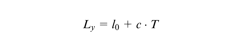
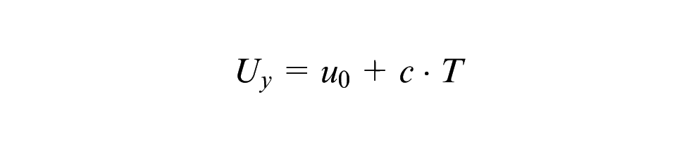
where
Specification limits on y are


To meet them, the following inequalities must be satisfied on temperature

where


Figure 3 shows the operating window resulting from tolerance specifications, as anticipated during the discussion of the example (c1 = c3 = 0.0001 mm °C−1, c2 = 0.0005 mm °C−1).
Operating window for the one-parameter case.
Now, let the tolerance limits on dimensions depend on an additional parameter, for example, a pressure p acting on the lower part from outside


Similar to the above case, resulting limits on y are


where, in addition to symbols defined in equation (2)


Tolerance limits on y given by equation (3) yield the following conditions on the two parameters

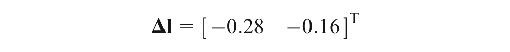
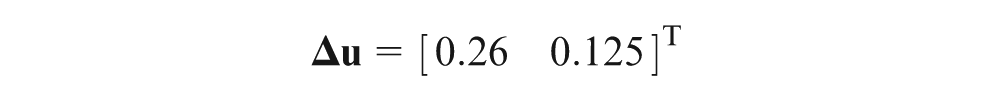
where Δl and Δu are defined as in equation (5). Again, Figure 4 shows the operating window resulting from tolerance specifications with the same effects of temperature (cTi = ci as defined above) plus a negative effect of pressure on dimension x1 (cT1 = −0.01 mm MPa−1, cT2 = cT3 = 0).
Operating window for the two-parameter case.
General case with single tolerance chain
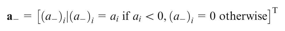
The above cases are now generalized into a procedure valid for any number of parameters. From the previously introduced symbols, the following vectors are defined

where
The immediate extension of conditions stated in equations (4) and (6) is the following pair of inequalities

where


and vectors

General case with multiple tolerance chains
For a further generalization of the procedure, the following vectors are defined
where

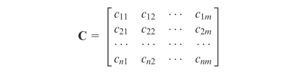
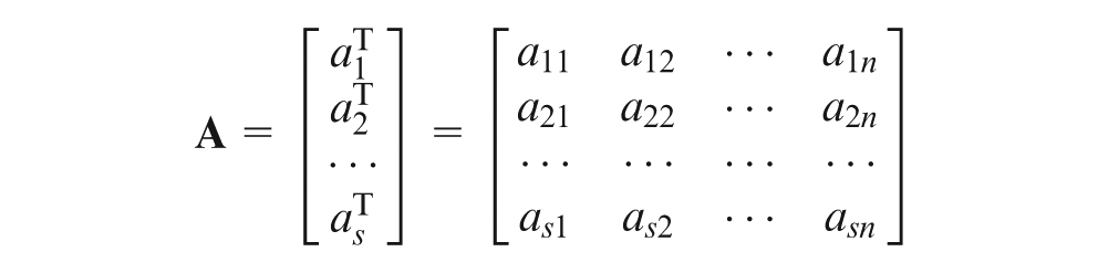
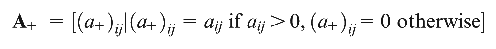
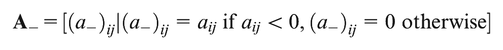
where matrix
The general condition on parameters is found by joining s scalar expressions such as those in equations (7) and (8) into a single vector equation

where


and matrices
Example
The drawing in Figure 5 shows a detail of a purge valve for plastics processing machines. The valve has the function of shutting off the flow of molten resin and deviating it into a discharge tank. The main parts of the assembly are the cylinder and the piston, both made of steel, and two graphite seals. The resin flows in a horizontal hole in the cylinder and in a corresponding hole in the piston. Seals are kept in interference with the piston by screw-mounted end plates, one of which is connected to the rod of an hydraulic actuator. When the piston is actuated, it aligns a discharge duct with the flow line in the cylinder.
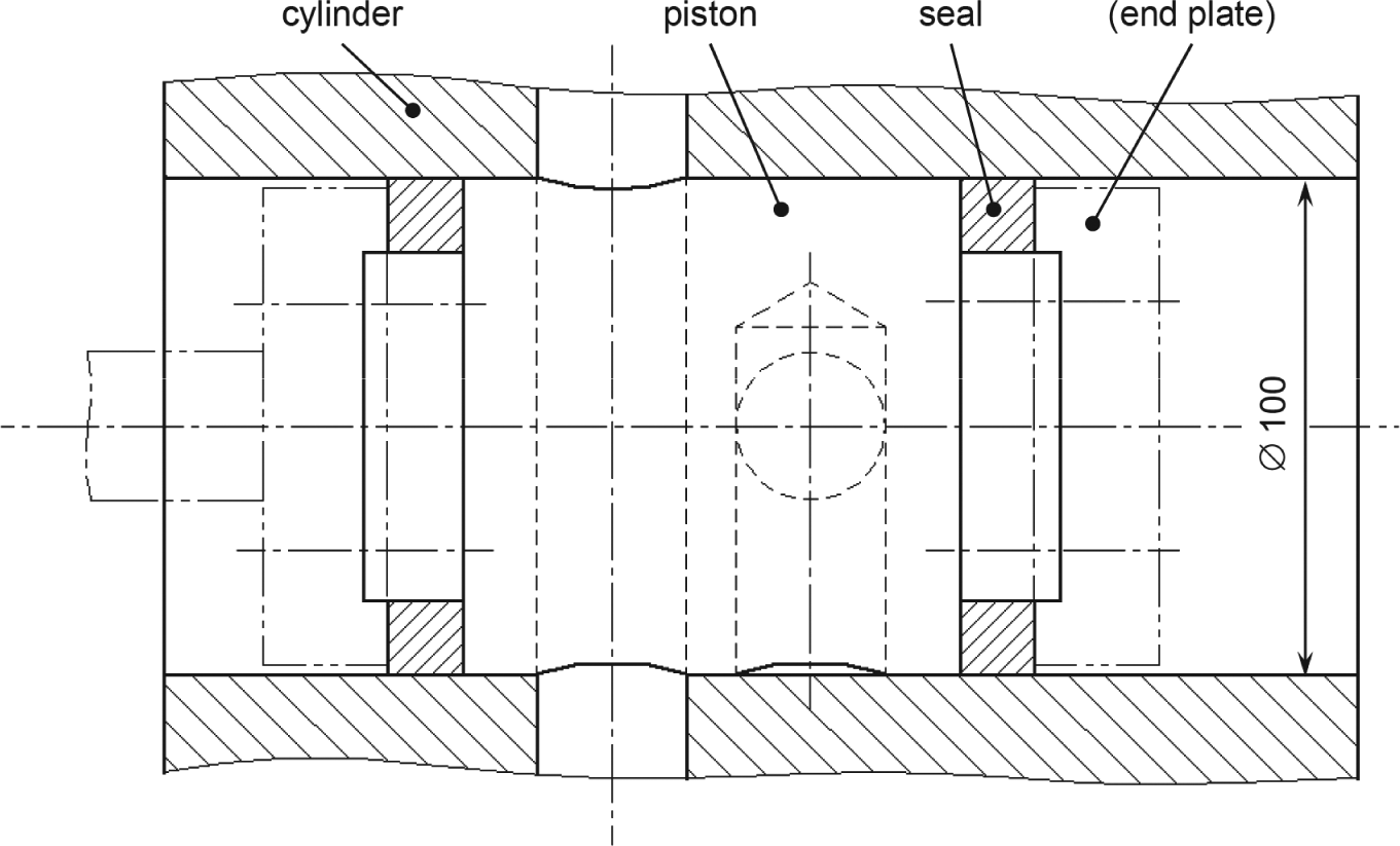
Detail of valve assembly.
The assembly behaves properly if two main functional requirements are controlled. The first one is the radial interference between seals and cylinder: resin may leak through the cylinder when interference decreases to zero, while damage of seals and increased motion resistance on the piston can arise when interference exceeds a given value. The second requirement is the height of the radial step between the outside surfaces of seals and piston: it can neither decrease to zero to avoid direct contact of piston and cylinder nor exceed a given value to avoid resin leakage between cylinder and piston. Violation of conditions on both requirements could eventually cause seizure of the piston in the cylinder.
Figure 5 also shows the common nominal value of the three functional dimensions on cylinder, piston and seals. Tolerances are specified on the diameters of cylinder bore and piston, while geometric errors are assumed to be negligible due to the accurate machining process. A tolerance is also specified by the supplier on the outside diameter of seals in the presence of a given lateral interference, which will be assumed to be regularly provided by the end plates.
Specified tolerances are such that the two requirements are satisfied for a new valve at room temperature with no resin flowing through. In operation, however, parts are in contact with fluid at temperature and pressure depending on the processed resin. The heating of parts causes differential expansion between steel and graphite. During valve actuation and in discharge mode, fluid pressure induces a concentrated bending load on the piston; this is transferred to the cylinder through the two seals that are radially squeezed. Moreover, wear builds up as long as the valve is used and causes a decrease of seal diameter with time, which can be regarded as linear to a first approximation. Within what values of temperature, pressure and time does the assembly guarantee the specified conditions on the two functional requirements?
According to the above considerations, part dimensions depend on three operating parameters: resin temperature T (expressed as difference in degree Celsius to the reference temperature of 20 °C), resin pressure p (in MPa) and number of cycles N from seals replacement. It is assumed that in steady-state operation, all parts have the same temperature of the fluid.
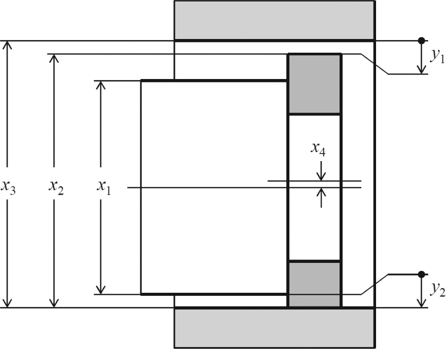
Requirements and related dimensions are depicted in Figure 6. Clearance y1 between cylinder and seals is allowed to take negative values (as interference is required) in the range from −0.80 to −0.10 mm. Relative height y2 of the seals with respect to the piston is allowed to take values in the range from 0.10 to 0.50 mm. The following functional equations are easily identified for the two tolerance chains

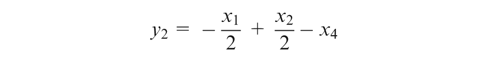
where x1 is the diameter of the piston, x2 is the outside diameter of the seal, x3 is the diameter of the bore in the cylinder and x4 is the eccentricity of the seal (assumed to be positive along the positive direction of y2). The following expressions include design tolerances and effects of operating parameters on dimensions


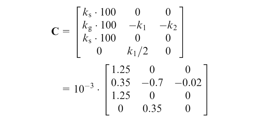
where ks = 12.5 × 10⁻⁶ °C−1 and kg = 3.5 × 10⁻⁶ °C−1 are the coefficients of thermal expansion of steel and graphite, k1 = 0.7 × 10⁻³ mm MPa−1 is the radial eccentricity induced on the seals for unit pressure and k2 = 0.02 × 10⁻³ mm is the loss of seal diameter due to wear for each operating cycle of the valve (under the simplifying assumption of constant wear rate). Equation (11) is derived from calculations involving thermal expansions and deformation of seals under the bending force acting on the piston; the latter is evaluated from detailed valve data (diameter of main resin pipe, length of the piston, stiffness and length of the seal).
Tolerance chains for the valve.
Given the above data, the problem can be treated according to the above-described procedure. Operating parameters are included in vector
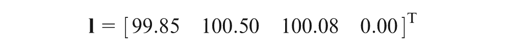
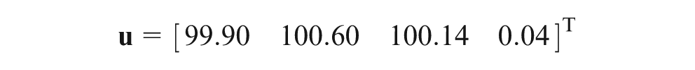
Requirements are expressed as vectors
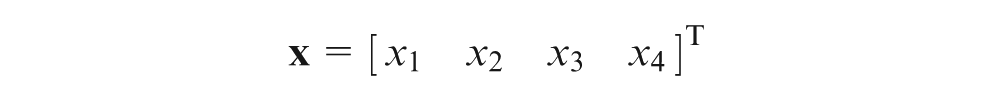
Dimensions are expressed as vectors
Effects of parameters on dimensions are expressed by matrix
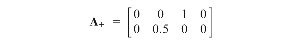
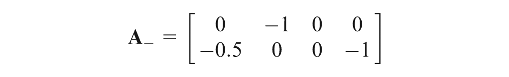
Stack up equations are given by matrix
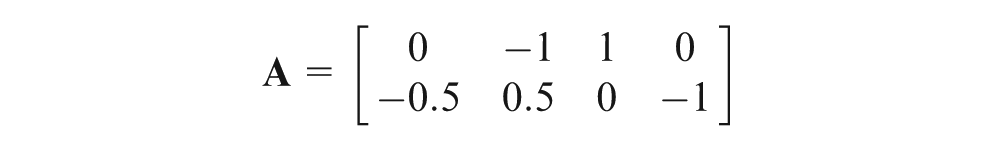
hence
The problem is solved by applying the conditions of equations (9) and (10)
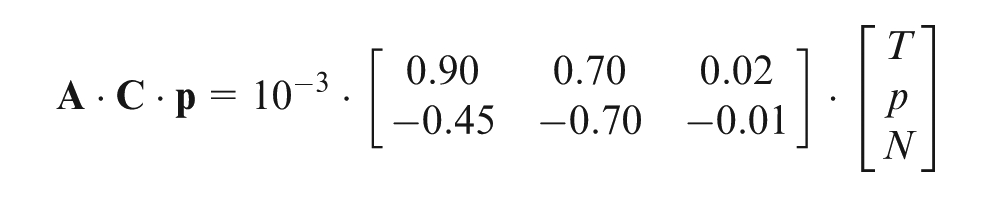
Four scalar inequalities result on parameters T, p and N


Figure 7 shows the operating window defined by equation (12) in a pressure–temperature diagram. Results are plotted for either a new valve (N = 0) or a valve after heavy usage (N = 1000). The allowable region of operating parameters is compared with the specified operating window of the valve, defined by temperatures in the range from 150 °C to 300 °C and pressures in the range from 10 to 70 MPa. As it is easily noted, conditions 2 and 3 in equation (12) have an impact on the nominal operating window and yield a critical region of high-temperature and -pressure values. Condition 2 is violated when the simultaneous increase of temperature (which makes the cylinder expand more than the seals) and pressure (which reduces the diameter of the seals) causes an excessive reduction of cylinder–seal interference (y1 > −0.10). Condition 3 is violated when the increase of temperature makes the seals expand less than the piston and exposes the latter to direct contact with the cylinder (y2 < 0.10). The wear of seals involves an additional significant reduction of the operating window.
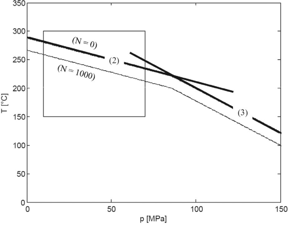
Operating window for the valve.
The above results allow to predict that some manufactured valves will incur resin leakage (at high temperatures and low pressure) and seizure (at high pressure) for a wide set of processed resins and with increasing probability along valve usage. The proposed procedure has allowed us to easily detect critical operating conditions, so that designers could modify tolerances in order to cover the whole operating window. This can be done by repeated applications of the procedure as shown in Figure 8. In a first step, lower and upper limits on bore diameter x3 are reduced by 0.06 mm; as a consequence, the occurrence of leakage is avoided and the operating window is only limited by the risk of seizure. In a second step, lower and upper limits on piston diameter x1 are reduced by 0.05 mm; such a change shifts leakage and seizure conditions away from temperature and pressure ranges specified for the valve. The quick response of the procedure allows to readily appreciate the sensitivity of the operating window to tolerance changes; for assemblies with limited complexity, few trials can be enough to select the tolerances to be modified and the new deviation limits.
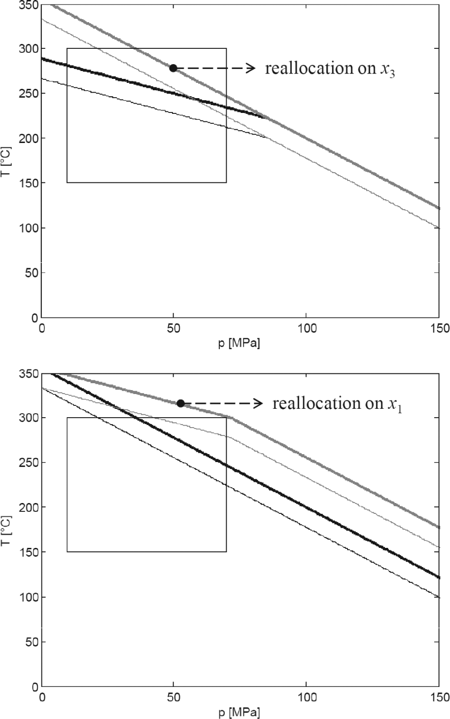
Effects of tolerance reallocations on the operating window for the valve.
Conclusions
A special case of tolerance analysis involves assemblies in which the geometry of part features depends on multiple operating parameters. Compared to the simpler case of dependence on only one parameter such as temperature, a designer cannot easily identify those combinations of parameters that impose the worst conditions for the functional requirements to be verified. This task would be made easier if a tool were available for determining the operating window compatible with a given set of specified tolerances. This article has presented a first approach to such objective based on restrictive assumptions on assembly design (dimensional tolerances, noncompliant and exactly constrained parts). These have allowed to develop a simple procedure for identifying the piecewise linear boundary of the operating window. The application example has confirmed the effectiveness and ease of use of the procedure, which lends itself to an easy implementation in an interactive software tool for designers.
The proposed method adopts an analytic approach to calculate the boundaries of the operating window as an alternative to a Monte Carlo simulation from dimension values sampled within tolerance limits as a function of the operating parameters. At current development stage, the price of this choice is that either the stack up equations or the effects of parameters are assumed to be linear. From an application viewpoint, the linearity assumption on stack up equations could be acceptable as most two- and three-dimensional tolerance chains can be linearized by several available methods. Even the consideration of geometric tolerances, not accounted for in this article, should not be too difficult since most geometric errors are usually added as linear terms to one-dimensional tolerance chains (at least on exactly constrained assemblies). The main limitation is that the assumption of worst-case stack up can give too pessimistic results for tolerance chains with many dimensions; to release this assumption, it will be interesting to study how the operating window changes when switching to a root sum square (RSS) stack up model based on normal distributions on dimensions. Regarding the linearity assumption on the effect of parameters, it has to be acknowledged that many parameters have actually nonlinear effects; this is likely to occur for speed and acceleration (in relation to inertia or drag effects), time (in relation to wear effects) and also temperature and forces at least in coupled thermomechanical problems such as those involving overconstrained assemblies. The procedure may not work properly in highly nonlinear cases, unless meaningful auxiliary variables with linear effects are defined from sets of operating parameters.
The procedure can only be used to verify how the operating window reacts in response to changes on part and assembly tolerances. The properties of the analysis model will be investigated, so that the procedure could provide suggestions to designers on how tolerancing is to be changed to selectively extend the operating window. Consistently, with the choice of an analytic approach, such objective will probably exploit differential properties of some vectors and matrices defined within the procedure, thus avoiding the need of sensitivity analyses or statistical plans of Monte Carlo simulations.
Footnotes
Funding
This research received no specific grant from any funding agency in the public, commercial or not-for-profit sectors.