
Abstract
Adhesive fixture systems have several advantages over conventional fixturing methods due to the following key capabilities: (1) can hold components with increased workpiece accessibility for processing, (2) can hold delicate components while avoiding excessive clamping forces, and (3) can hold and support complex or variable geometry parts. The development of high-strength structural adhesives that can be rapidly and controllably cured now offers much greater scope for holding complex parts than the traditionally used low-strength adhesives, waxes, or low-melt alloys currently used in niche applications and ad hoc fixture systems. This article first evaluates the workholding performance, capability, and suitability of an ultraviolet-activated adhesive fixture system to hold aerospace-type components; this includes quantifying the mechanical properties of the adhesive bond and assessing the influential factors (surface finish, contamination, geometries of bonded surfaces, and adhesive-curing time). Then the article presents concepts of adhesive fixture system for rapid location and bonding/de-bonding for enhanced accessibility on machine surfaces. A set of fixture demonstrators and their effectiveness are evaluated in terms of maximum reaction forces, dynamic performance, and ease of use. From this research, it becomes apparent that the adhesive fixture system approach provides new opportunities for workholding geometrically complex components for high-demanding applications (e.g. manufacture of aerospace parts).
Introduction
One limitation of conventional mechanical fixturing methods (clamps, collets, and threaded fasteners) is that they often do not allow unimpeded access to all the workpiece surfaces that require machining or inspection. This limitation increases the number of required fixtures, machines, and operations and has knock-on effects on increasing processing/set-up time, costs, and manufacturing inaccuracies from repositioning components between operations. Mechanical workholding systems become difficult to use particularly when delicate, small, or difficult-to-hold parts require processing. The level of clamping load required to effectively secure components unavoidably stresses the component which can cause low-rigidity components to plastically deform or delicate components to fail. Workpiece deformations/deflections resulting from the fixture clamping load are significant limiting factors that govern the achievable accuracies in machining. Other commonly used non-mechanical methods of workholding, such as magnetic systems and vacuum chucks, also possess well-documented limitations; 1 they can be expensive and require the components to be magnetic or have vacuum suitable surfaces; additionally, they need ancillaries (electrics/pneumatics) that can hinder the workspace and therefore make them less attractive for high-accessibility machining of geometrically complex parts. Moreover, components held with these methods are susceptible to deformation from clamping loads.
Non-conventional workholding
Several designs of non-conventional workholding technologies have been developed to address the needs of various engineering fixturing applications. 2 Many of these ‘novel fixturing solutions’ have inherent limitations. In this respect, low-melt alloys, adhesive resins, waxes, and water ice have been used to encapsulate irregular or delicate parts for easy processing. Encapsulation is often undesirable as the parts have to be removed from the encapsulation media. Low-melt alloys such as lead–bismuth–tin composition 3 are stronger than waxes; however, small amounts of such materials left on the surface of sensitive parts (e.g. turbine blades) can cause corrosion problems, 4 which is to be avoided. Moreover, some industries (e.g. aerospace) are concerned about the possible surface contaminations that might cause reduction on part performance, this is not to mention the possible environmental and safety impacts on the workplaces.
Magnetorheological fluids (MRFs), mixtures of ferromagnetic particles suspended in liquids, have also been used to hold parts during machining operations;5,6 the components are locked in place when a magnetic field is applied to the MRF that changes its stiffness. However, the MRF only achieves semi-solid state 7 and hence is not suitable for rigid holding where a completely stiff structure is required. This causes these systems to suffer from an inability to maintain effective component clamping or accurate component position when subjected to prolonged static or rapidly changing dynamic loading, a loading situation that is commonplace in many processing operations.
Horst-Witte’s Ice-Vice™ is capable of holding delicate parts with highly irregular shapes using water ice. This system incorporated cooling and heating elements for clamping (freezing) and de-bonding (melting).8,9 Another system, the GF series icing plates developed by Capens, can be used for milling, grinding, turning, or custom applications. 10 Holding strength is still somewhat limited (2 N/mm2) 11 compared to that of the adhesive fixture system (AFS) presented in this article. Also, ice clamping systems are fundamentally restricted by an inability to use cutting fluids above 0 °C.
The use of wax, as a method of holding parts to ease their manufacture, has been considered as a traditional solution especially to support processing complex/delicate parts. Mitee-Grip™ is a heat-activated wax-based adhesive.12,13 A workholding system by Lapac et al. 4 uses a liquid organic resin that is deposited hot and then quenched. In this approach, the fixture systems need to quickly secure parts while ensuring that no part movement occurs within the system in this period; however, this depends on the quenched capability of the wax that can, sometimes, be slower and less controllable depending on the design solutions of the workholding system.
A solution developed by Martinez et al. 14 details a method of securing an object to and removing an object from a surface using heat and a thermoplastic adhesive. The heating surface comprises a foil film or wire embedded element in a thermoplastic adhesive and has been used in microchip assembly.
Waiting even a few minutes for waxes to set, water to freeze, or adhesive to cure makes most of the systems less than effective. Workholding systems that can be ‘triggered’ in seconds are likely to be much more attractive for industry. The use of waxes, water ice, and MRF simply does not achieve the high holding strength that is required for machining parts in industrial environments, where high material removal rates are required.
Adhesive-type fixtures
Although the idea of adhesive workholding is not particularly new,15,16 adhesives that have been, and continue to be, developed for various general gluing applications now offer substantial advantages for workholding performance and ease of use. The use of commercially available photoactivated adhesive 17 is particularly well suited for workholding due to a combination of high bond strength and rapid and controllable curing that is triggered exactly when the operator requires.
A technique known as photoactivated adhesive workholding (PAW) has been developed13,18,19 and commercialised by Master Workholding, Inc., under the name LAAG™ (light-activated adhesive gripper).20,21 There are numerous potential advantages to using this particular adhesive workholding system: maximum workpiece accessibility, flexibility of holding position, high holding strength (6000 lbf/in2), and short cycle times. The LAAG system uses a commercially available ultraviolet (UV) spot lamp and a light guide to direct the UV light through gripping pins to rapidly cure a photoactivated adhesive applied to the gripper pin surface. The PAW/LAAG system has been reported to use both laser radiation and simple mechanical breakage systems to de-bond components; the laser adds to the complexity and cost of the design solution, while the mechanical de-bonding is likely to have a negative influence on delicate/low-stiffness components.
However, to enable such solutions to be used in more demanding workholding applications, detailed examinations on the characteristics of the bonding interfaces (e.g. geometries and roughness), surface contaminations (e.g. grease and cutting fluids), and loading types (e.g. impact and strain rates) of the joint interfaces as well as in-depth analysis of the performance of these fixturing solutions under dynamic machining conditions (e.g. milling) need to be performed if such systems are to be utilised in industry. Without these studies, the adhesive fixtures are likely to be used only in simple applications (e.g. stiff and simple-shaped parts), situations in which their key advantages might not be fully exploited.
Challenges in AFS design and exploitation
To enable further development and use of the adhesive fixture solutions, the following challenges need to be addressed.
Mechanical properties of the adhesive bond
The strength of the joint has to be known in relation to the loading configuration/regime experienced during the manufacturing process for which the fixture is to be used. For certain adhesives, the basic mechanical properties are available direct from the manufacturer. However, for industrial use, the performances of the adhesives in application-specific conditions (tension, compression, shear, torsion, impact loading, etc.) are often needed.
Influential factors on adhesive bond yield strength
An assessment of which factors influence or are likely to cause degradation in the bond strength must also be made. These include factors relating to the component such as the type of material, surface roughness, and joint geometry (i.e. angle, conformal/non-conformal curvature). Also, the effect of contamination and exposure to cutting fluid on the adhesive bond must be quantified.
Dynamic analysis
The characteristics of the joint when considering their properties (e.g. stiffness of the bonding between dissimilar materials) and their response to dynamic loading during machining operations, while being influenced by joint thickness, need to be understood.
Operational best practice
This must be addressed including ease of use, fixturing time (loading, unloading, etc.), method of adhesive application, and comparative cost analysis in terms of equipment, consumable, and operating costs.
De-bonding and residual adhesive removal
Effective de-bonding and easy removal of residual adhesive can be a substantial issue for many applications. Ideally, the fixture should be ready to be reused with little effort and residual adhesive removed from the final component surfaces without damaging them and adversely affecting location elements or moving surfaces. Material compatibility between the workpiece, the adhesive, and the methods used to remove it should be sought.
Key design concepts of AFS elements
The key element of the adhesive fixture is the design of the adhesive fastening elements and how these are arranged or integrated within the bulk fixture material. The sophistication of custom AFS is dependent on the requirement of particular applications.
Simple fastener-type system
The simplest form of UV-activated adhesive fixture consists of modifications to standard-type fastener elements (e.g. pins, bolts, and set screws) that have been modified to contain a simple optical pathway (e.g. toughened borosilicate, quartz, perspex, fibre, or rod). These fastener elements may be screwed into and arranged as required within a fixture plate. The other constituent parts, that is, the external light source, light guides, adhesive type, and automated adhesive delivery systems, are commercially available products used widely within the UV adhesive-curing industry. The number, position, and size of fastener elements are largely governed by the geometry of the workpiece and the loading requirement from the process.
Bulky/rugged components held with simple bolt-type adhesive fasteners may be effectively released by unscrewing the fastener, thus stressing the adhesive joint in excess of its holding strength or simply knocking the component from the fixture through utilising the somewhat lower impact strength of the adhesive joint. This approach is not satisfactory for delicate/low-stiffness components where the larger forces generated during de-bonding may damage the parts. Components may require larger bond contact areas, or alternative geometries, making them unsuitable for simple fastener-type systems. A more self-contained integrated adhesive fixture may be required to accommodate improved operational functionality or deal with component geometry. As a result of these aspects and challenges that need to be addressed, new AFS design concepts have been developed to extend the capabilities of adhesive fixtures.
Workpiece de-bonding
Whereas attaching the parts to the adhesive fixture is relatively easy, the main challenge lies in the rapid and effective removal of parts after processing and this can require new solutions. Two distinct methods of de-bonding are presented here which can be categorised as using either a low stress–inducing mechanical method or through the application of heat to thermally break the adhesive bond.
Low-stress mechanical/pin fixtures
The low-stress mechanical joint break method involves breaking the adhesive joint in a controlled and sequential way at the planes that does not stress the component and/or by providing support for the component close to where the joint plane is being broken.
Figure 1 illustrates this concept and shows the de-bonding sequence. During stage 1, the pin is retracted and the adhesive joint is stressed. The support of the adhesive joint on the sides of the pin housing prevents the component being overstressed when the first joint breakage occurs. During stage 2, the pin is pushed forwards causing the joint to shear at the second breakage point allowing the component to be released. After removal, the component requires post-processing (not necessarily mechanical) to remove the adhesive left on the workpiece surface.
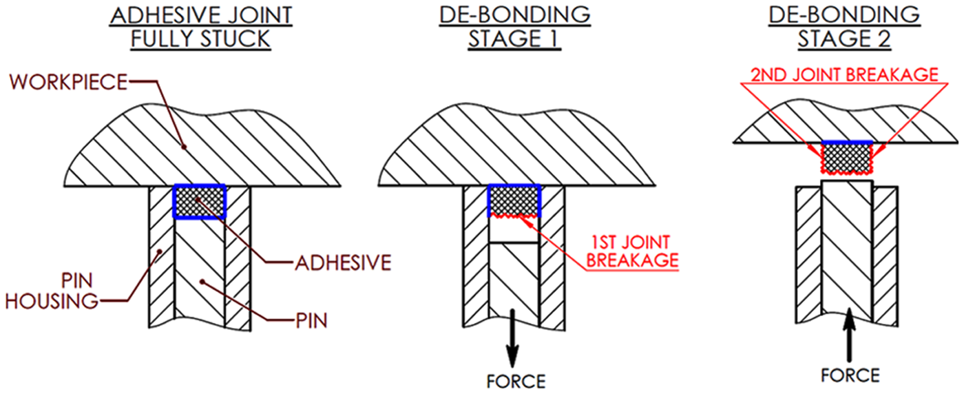
Concept of adhesive bond breakage while minimising stress in workpiece.
Although this approach can add complexity to the fixture, the fact that it can be used in an array makes it suitable for relatively large adhesive joint areas of contact where the integrity of the joint can be negated without the need for excessive loading. An example is shown in Figure 2 where an array of optically transparent pins are able to be moved relative to the pin housing and workpiece causing the de-bonding sequence outlined in Figure 1 to be achieved.
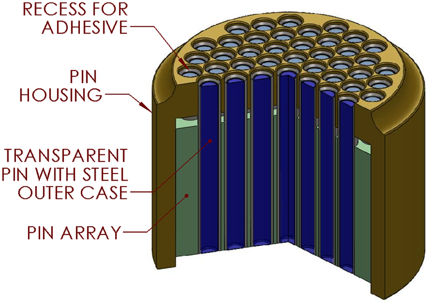
Three-dimensional sectional view of adhesive pin fixture concept A.
An alternative pin fixture arrangement is shown in Figure 3 with the pins able to be adjusted vertically to accommodate variations in workpiece surface geometry. A variety of pin configurations may be possible such as threaded, hexagonal, and the vertical position actuated and set either by locking the height of the individual pins or by clamping the pins together from the side. The pins must contain either an optical transmitting material or an integrated UV light-emitting diode (LED) for curing the adhesive. Typically, three pins can be permanently locked and used for workpiece location. Other pins can contain a small central hole for adhesive delivery directly to the bond interface.
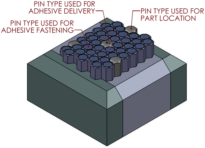
Three-dimensional view of adhesive pin fixture concept B.
Thermal de-bonding
Embedded electrical resistor
The application of heat is an effective mechanism for de-bonding glued parts. The strength of the adhesive used in this study (Dymax 6-621 Multi-Cure)22,23 has been found to lose all but an insignificant fraction of its strength when raised to temperatures in excess of 180 °C. Alternative lower strength UV curable adhesives (Dymax SpeedMask 728G) 24 are also available that de-bond, and are easily removed, at much lower temperatures (below 100 °C). As placing components and fixtures in an oven is not feasible, the key to success in using a thermal mechanism of de-bonding is to incorporate heating elements into the adhesive fixture/fastening element to provide rapid heating of the adhesive joint. These elements can radiate heat through the optically transparent material, or conduct heat via thermally conductive surrounding material, to the surfaces in contact with the adhesive thus enabling the de-bonding. A rapid thermal ramp up is required not only for a quick de-bonding operation but also to prevent inducing thermal fields into the workpiece/fixturing system.
Figure 4 presents a few general concepts for thermal de-bonding. Optically transparent thin film heating elements can be used in larger plates within customer fixtures or smaller discs for adhesive fastener elements (Figure 4(a)). Embedded heating elements (Figure 4(b)) or resistive wire can be used to thermally destroy the bond, heat being channelled to the required areas within the fixture through the use of high thermally conductivity fixture suitable materials and ceramic insulation. Induction heating coils could be used to heat a thermally conductive pin directly via induction (Figure 4(c)). Induction-cured adhesives could also be used as an alternative to UV cure or induction used to directly heat partials within a UV adhesive as a means of thermal de-bonding.
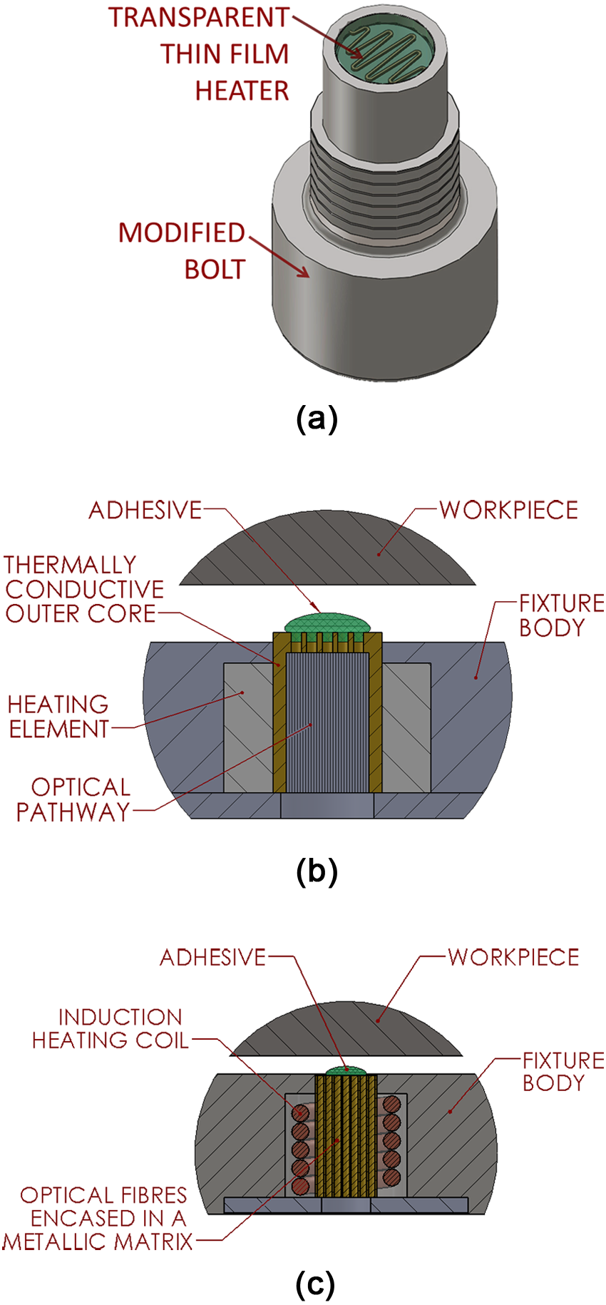
AFS fastening element: (a) fastening element incorporating an optically transparent thin film heating element; (b) AFS with embedded conductive heating element; and (c) AFS with embedded inductive heating element.
Bond strength characterisation and assessment of main influencing factors
In order to prove the viability of the AFS for industrial applications, a thorough assessment of its capabilities in terms of bond strength and other influential factors is essential. For this, a comprehensive experimentation was conducted on the adhesive joint. Throughout the entire experimental programme, a high-strength adhesive, Dymax 6-621 Series Multi-Cure (urethane acrylate), has been used to bond various surfaces by using a curing system consisting of a UV spot lamp and a light guide (OmniCure™ Series 2000 – Figure 5). To enable the curing of the adhesive with UV light, a transparent material needs to be utilised for the surfaces to which the part needs to be bonded. In the following bonding strength tests, the adhesive fastening elements consisted of Quartz 214 grade rod (Ø8 mm × 20 mm with rounded R0.5 mm edges and optically transparent lap-polished faces) bonded into a stainless steel supporting tube (Ø10 mm × Ø8.1 mm × 20 mm). This allowed the adhesive fastening element to be mechanically tested and ensured failures occurred at the adhesive bond interface and not due to point loading on the quartz from the testing machine’s gripping jaws. When bonded to a steel counterface surface (Ø12 mm × 40 mm), this replicated a simple adhesive assembly of a fastening element and component.
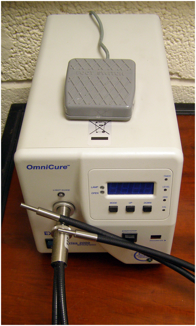
Equipment for adhesive curing.
In order to ensure the consistency of sample assembly, a custom gluing jig was used (Figure 6). A ring of shim that axially separated the two halves of the jig ensured that an accurate and constant joint gap of 0.125 mm was produced in each sample. Concentricity and parallelism of the sample were controlled via location fits on the mating surfaces of the jig halves and the sample held in the jig while gluing. The bonding cycle was as follows: (1) surfaces to be bonded were degreased with ‘SuperSolve AS’; (2) one drop of adhesive was applied to the fastening element’s surface; (3) the counterface surface was brought into contact with the fastening element; and (4) UV light was applied through the transparent material of the fastening elements to cure the adhesive.
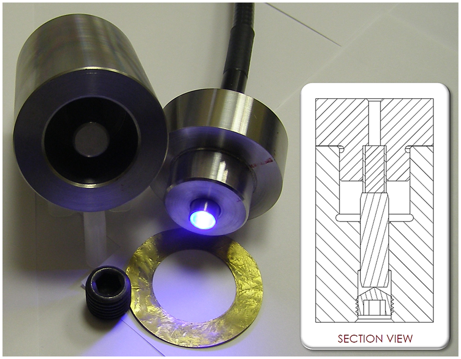
Test sample gluing jig.
In order to verify the holding strength of the selected adhesive, a series of tensile tests were performed using an Instron 5569 universal test machine (calibrated load accuracy of 0.5%) on the standard butt-jointed glass and steel bonded test samples. The average failure load of the standard butt-jointed test sample was 2247N (ultimate tensile strength (UTS) of 28.62 N/mm2). However, the brittle fracture of the adhesive joint varied quite considerably between the six samples measured (standard deviation 462 N) and produced a reasonably large scatter of failure load values that were as low as 1435 N and as high as 2652 N.
Tensile tests were conducted to determine the effect of a few influential factors considered to be of high importance to workholding; the variation intervals for the factors were selected to encompass extreme scenarios that might be experienced during industrial use. These factors included the effect of joint geometry (Figure 7), joint surface roughness (1.75, 0.13, 0.012 µm Ra), test strain rate (10, 1, 0.1 mm/min), post-cure exposure to cutting fluid (0, 100, 1000 min), pre-cure exposure to contaminants (degreased, fingerprint, grease smear), and UV exposure time used to cure the adhesive (1, 3, 10, 100 s).
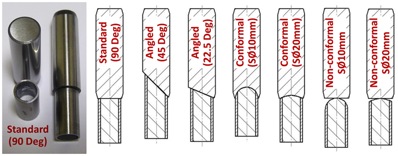
Samples for mechanical testing of the bond strength.
Based on the average of three replications for varied values and six for standard samples, Figure 8 shows the summarised results of the tensile tests of the bond strength in various conditions from which the following conclusions can be drawn:
Experiments on the curing times of the adhesive identified 10 s as optimal value (Figure 8(a)); longer curing times did not show substantial improvements in bond strength. Acceptably short (e.g. 10 s) curing times make the technology attractive to industrial end users.
While maintaining a constant, optically transparent, finish in the glass surface, the workpiece surface textures were altered to simulate the extreme values obtainable from different processing methods: (1) Ra = 0.012 µm − polished to a mirror finish; (2) Ra = 0.13 µm − fine ground finish; and (3) Ra = 1.75 µm − irregular rough surface. Figure 8(b) shows a significant, but not overtly dramatic, decrease (36%) in bond strength when polished workpiece surfaces are used over the standard samples. As such ultrafine workpiece surfaces are unlikely to be experienced in real machining environments, the results are encouraging showing relatively little sensitivity of the bond strength to surface roughness above Ra = 0.13 µm. It should be noted that additional non-quantitative tests on alternative materials (e.g. aluminium) suggested that the effect of surface roughness was material dependent. Therefore, case-specific conditions should be investigated separately when considering use for new application.
Strain rates of 0.1, 1, and 10 mm/min were tested; however, no appreciable difference in failure load was recorded within the tested variation intervals.
Maximum tensile load decreased, relative to degreased surfaces, by 23% and 94% when light (greasy fingerprint) and heavy (light grease smear) contamination occur (Figure 8(c)). This proves that if AFS is to be used in a real industrial environment, a minimal degreasing procedure should be applied; a simple wiping with a cloth soaked in SuperSolve AS proved to be enough to provide satisfactory results.
There was no evidence of bond weakening when the test samples were submerged for 100 min in Hocut3380 emulsion cutting fluid (extensively used in machining of aerospace components); however, the prolonged exposure (e.g. 1000 min) showed a loss of 62% of the bond strength. The results are encouraging since it can be observed that the bond does not lose its strength at cutting fluid exposure times (e.g. 100 min) that enable reasonably lengthy machining operations; however, these results are specific for this cutting fluid and hence any user of the technology should perform similar tests for any other cutting fluid exposures.
Most of the advanced fixturing solutions require clamping on non-flat surfaces; hence, bonds of surfaces at different angles have been tested. In this way, the tensile testing resulted in the bond strength evaluation of real-world application realistic conditions that combined tensile and shear loads. Figure 8(d) shows that on average, a loss in bond strength of 26% can be encountered if the surface angle varies from 90°to 67.5°. As the angle moves to 45°, the area of contact increases; therefore, the calculated stress value decreases from 67.5° to 45° but the ability to support load increases.
Measurement of a standard test sample loaded in shear recorded a load failure of 2180 N, which demonstrated that the adhesive bond could be utilised on a wide range of workholding systems for machining operations.
Moreover, the contact surface geometries that need to be bonded may not be flat in real industrial fixturing applications. Figure 8(e) shows that the decrease of radius of the conformal contact surfaces leads to a significant decrease (72% at SØ 10 mm spherical diameter) of bond strength. This is likely due to the increase of percentage of the shear loading around the bond when smaller curvatures of the joint surfaces are used.
Similarly, there might be fixturing cases when non-conformal (e.g. flat versus curved) surfaces need to be bonded, and these situations have been tested as shown in Figure 8(f). Here, it can be noted that with the decrease of curvature, the bond strength can significantly decrease (92% at 10 mm spherical diameter).
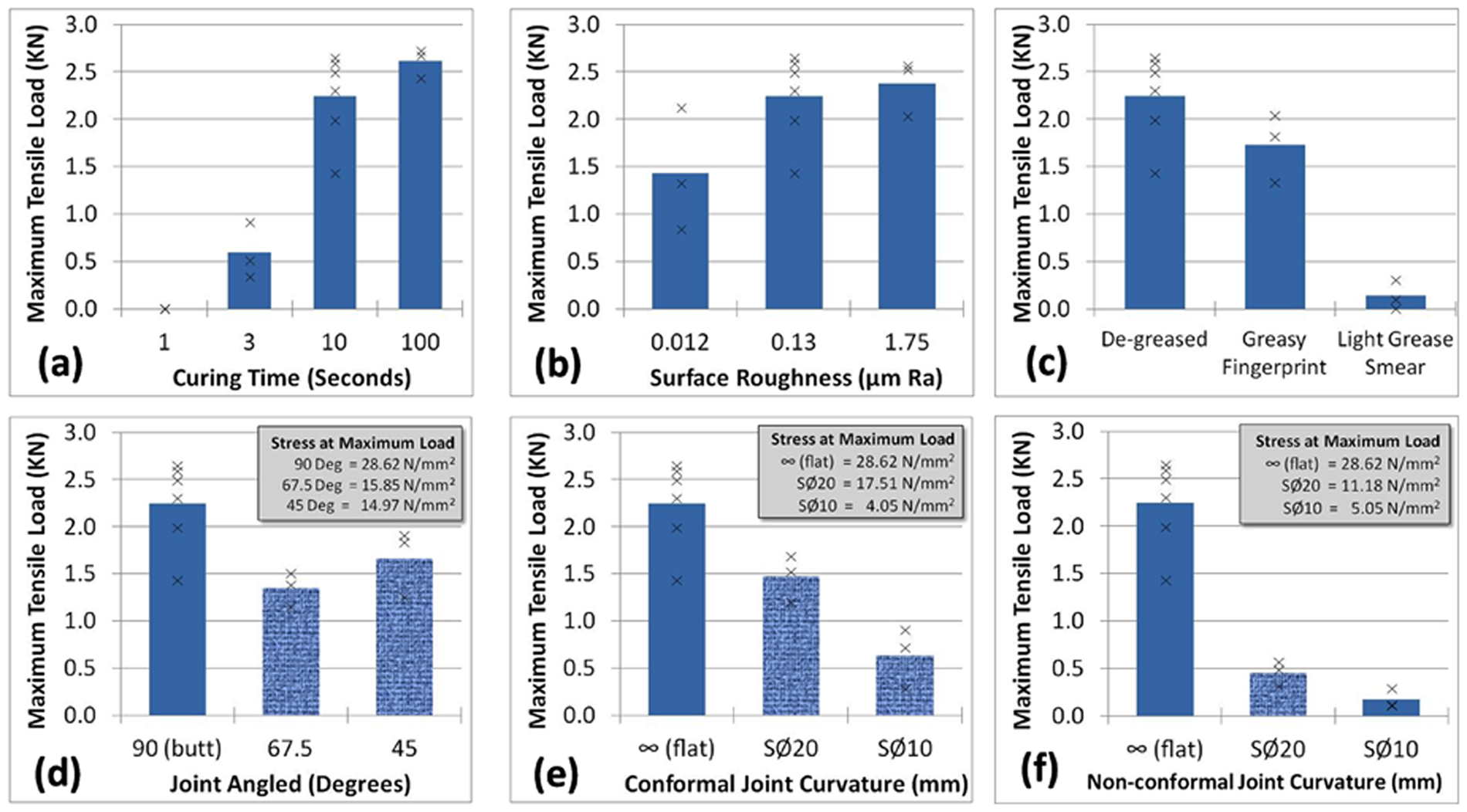
Graphs showing the failure load in tension of the adhesive joint test samples and illustrating (a) effect of curing time, (b) effect of surface roughness, (c) effect of surface contamination, (d) effect of joint angle, (e) effect of conformal joint curvature, and (f) effect of non-conformal joint curvature
Additionally, 16 impact tests were conducted on the previously described test samples using an Avery-Denison Izod impact test machine, with a striking velocity of 3.46 m/s and with 2.7 J of potential energy. Very low, but consistent, values of absorbed energy by the bond were recorded (0.16–0.19 J), which highlights the poor toughness of the standard samples adhesive joint. Assessment of surface roughness, joint angle, and conformal spherical geometry revealed that the samples were influenced little by these factors with all these samples tested recording values ranging between 0.15 and 0.22 J. Additional (non-quantitative) observations highlighted that although high impact strength is still not achieved, substantial improvements can be realised through slight modification to the joint construction. As the poor impact strength and brittle failure mode of the adhesive joint may well be a limiting factor of the fixture for some processing options, scope for further study in this area remains.
The above results cover by no means all the engineering aspects that need to be taken into consideration when AFSs are designed. It is up to the fixture designer to conduct preliminary testing to ensure that the bond strength reaches values that correspond to the desired workholding applications. These results constitute a summary of the extensive testing carried out to enable the design of the fixtures for particular machining applications that are shown in the following paragraphs.
Evaluation of AFS during machining operations
A set of machining trials have been carried out to assess the capability of AFS. Firstly, rigid parts (i.e. of rectangular shape) were milled and ground (at large distances from the holding point) in both production-like and very aggressive cutting parameters. Then, trials on test pieces replicating real components have been ground using an AFS with design specifications to meet industrial needs.
Milling of a rectangular workpiece
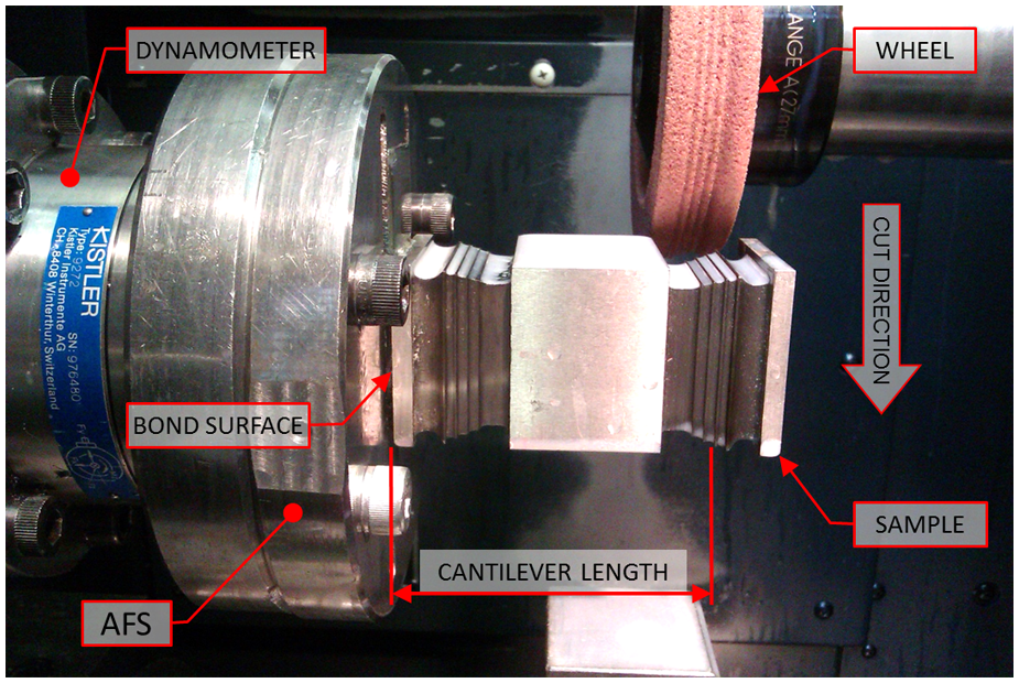
With a better understanding of how the performances of the bond strength can be affected by various set-up parameters, a simple AFS has been designed to enable the evaluation of the performances of the bond under repetitive and highly dynamic loading exercised by milling operations. Figure 9 presents a holding system that includes a base plate (1) containing four adhesive fastening elements (2). The adhesive fastening elements each consists of an M12 fine pitch steel socket head cap screw with an embedded quartz rod (Ø8 mm × 15 mm) for the transmission of 10 s of UV light to the adhesive interface. A workpiece (3) made of Ti6Al4V aerospace superalloy of rectangular form (100 mm × 45 mm × 20 mm) and surface roughness of 1.09 µm Ra on the held face of the workpiece was used in the milling trials. As indicated in Figure 5, the AFS incorporates a tri-axis accelerometer (4) (Kistler 8792A100) bolted to the sample, while the base plate is bolted (5) on a tri-axis dynamometer (Kistler 9272); sensory signals were acquired at 10 kHz sampling rate using a National Instruments data acquisition card and afterwards processed using MATLAB codes developed in-house. Process monitoring has been put in place to enable the evaluation of the bond strength as well as any capabilities to damp vibrations; this has been performed by comparing the AFS against a conventional fixturing solution on which the adhesive fasteners (2) have been replaced with four socket head shoulder bolts (Ø10X16-M8) that rigidly hold via tapped M8 holes in the workpiece. Milling trials have been performed on a five-axis Makino A55 machining centre (Figure 10) equipped with a two-teeth Ø25 mm cutter (SECODEX R217.69-2525.4-16) using the following cutting parameters: radial depth of cut ae = 22.5 mm; feed per tooth fz = 0.10 mm, peripheral cutting speed Vc = 65 m/min, and Hocut3380 cutting fluid flood supplied at ∼50 bar. To progressively test the strength experienced by the four ‘adhesive pins’, the depth of cut has been increased as per the following values: ap = 0.25, 0.5, 1.0, 3.0, 5.0 mm.
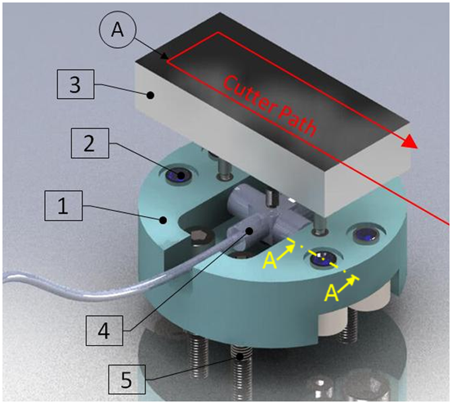
Design of AFS #1 used for milling of a rectangular workpiece.
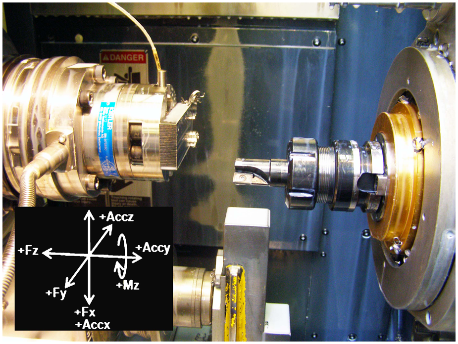
Photograph of the experimental set-up for initial machining trials.
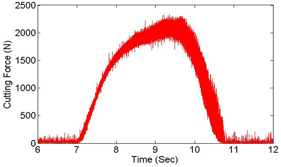
Milling trials showed that the AFS was able to securely hold the workpiece at depths of cut up to ap = 3 mm. Figure 11 shows the resultant FR cutting force (within xy plane) at which the AFS holds the part when using a depth of cut ap = 3 mm, and Figure 12 shows the x-direction acceleration experienced by the workpiece. The dynamic nature of the loading is apparent where the load (Figure 11(b)) and acceleration (Figure 12(b)) are seen to reduce to zero as the cutter’s rotation causes neither of the inserts to be in contact with the workpiece. A regular, and typical, loading pattern is recorded where one of the inserts records a slightly higher cutting force than the other. In these conditions, the spindle monitoring system recorded 1.2 KWof power being used by the 3-KW rated spindle motor while sample surface roughness of 0.43 µm Ra was obtained.
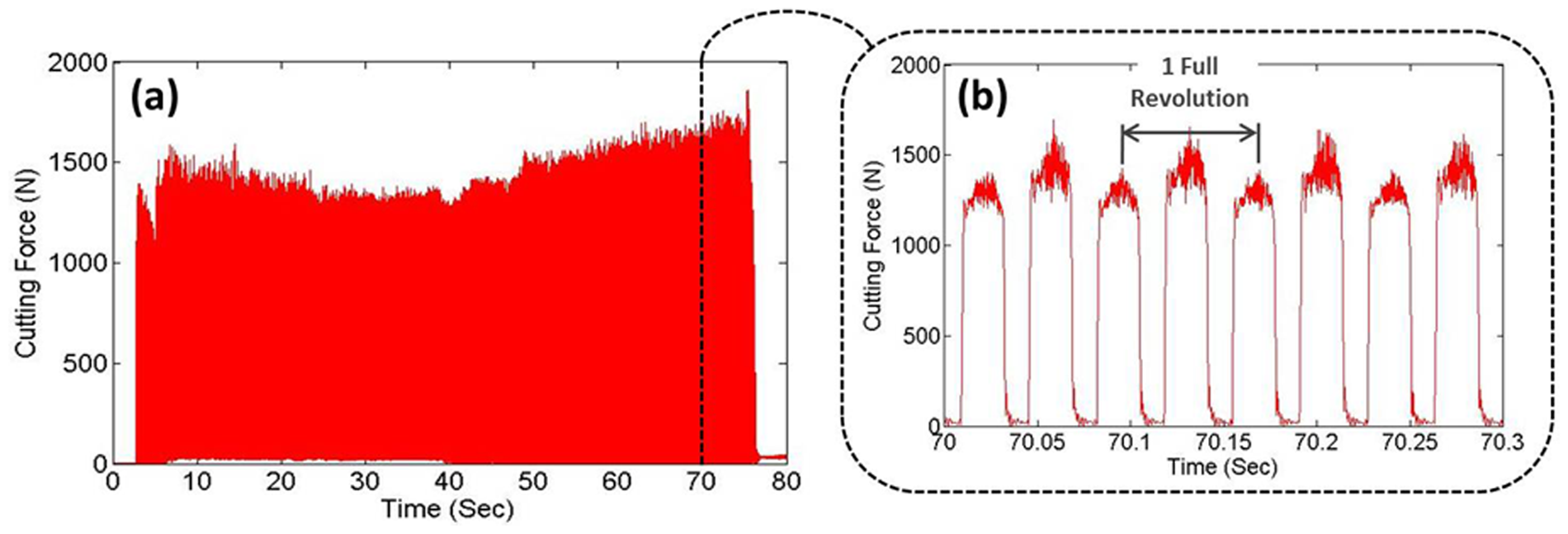
AFS milling fixture trial at ap = 3 mm: (a) FR resultant force and (b) zoomed in view of its pattern.
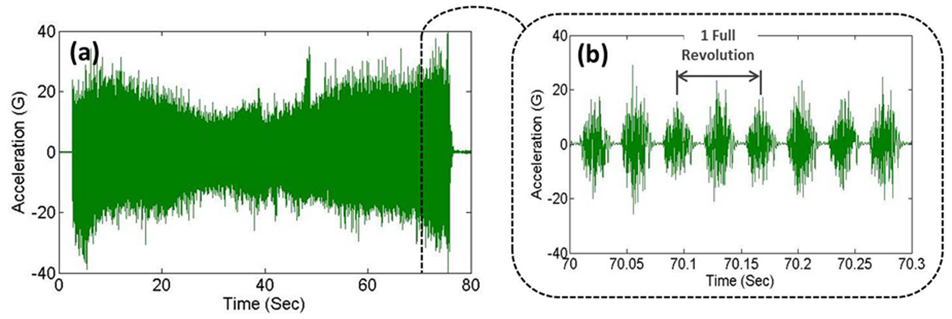
AFS milling fixture trial at ap = 3 mm: (a) acceleration in x-direction and (b) zoomed in view of its pattern.
During the most aggressive cut, ap = 5 mm, the bonding failed 38 s into the 90-s cutting cycle; taking into consideration the specified cutting parameters, this is a substantial depth of cut that is not commonly used in machining of surface integrity–sensitive components. Prior to failure, a reasonable surface roughness was achieved (1.61 µm Ra). The adhesive joints failed as the milling cutter began to take the turn (point A in Figure 9), whereas FR resultant force values (in excess of 3000 N) and absolute value of x-direction accelerations of around 1000 m/s2 have been recorded.
It should be noted that on TiAl6V4, such aggressive levels of cutting parameters (i.e. ap = 5 mm) yielding extreme cutting forces are rarely used due to the inherent metallurgical transformation that could occur in the workpiece material with negative effects on the service life of the machine’s components. This aggressiveness is exemplified by the 3-KW cutter spindle power using up to 2.75 KWprior to failure. It should also be noted that only four adhesive pins were used making the actual bond contact area very small (314 mm2) compared to the size of the workpiece base (4500 mm2). By increasing the area of adhesive joint using more adhesive fastening pins, larger forces will be sustainable. Hence, the performance of the AFS in this trial was considered well within the target application.
Cuts taken with the adhesive fasteners were compared to the closest mechanical equivalent holding method, that is, adhesive fasteners removed and replaced with bolts that screwed into tapped holes in the base of the Ti6Al4V workpiece (Figure 13).
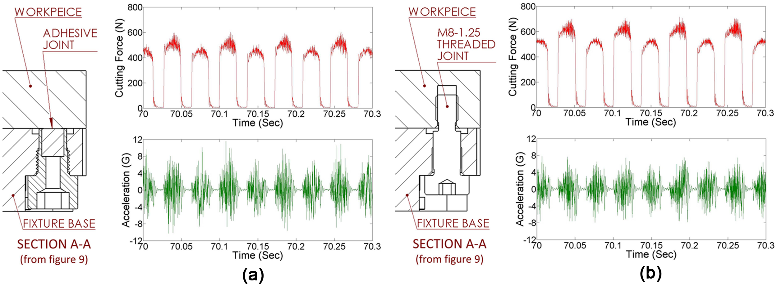
Force and acceleration signals (ap = 1 mm) for two fixture footprints: (a) AFS pins and (b) mechanical equivalent.
A direct comparison of force, torque, acceleration, spindle power, and surface finish revealed that there was no appreciable difference between the two holding methods; this demonstrates that the adhesive fixture was equally capable of holding the workpiece in terms of fully transmitting the cutting load to the dynamometer.
VIPER grinding trials of rectangular parts
In order to explore the AFS holding potential to support high cutting forces on cuts made on cantilever part set-ups, an Inconel 718 test sample (Figure 14) was bonded to an adhesive fixture plate using the same Dymax 6-621 UV adhesive. A simple butt-type joint was used to hold the square base of the sample with a rectangular (49.5 mm × 32 mm) bonding element contained in the fixture plate; the cut was made at 82.5 mm distance from the holding point.
Inconel 718 test sample (49.5 mm × 49.5 mm × 100 mm, Ra = 0.26 µm) bonded to adhesive fixture (#2) plate
A succession of very impressive performance extreme removal (VIPER) grinding passes were conducted using a Makino A55 machine centre and a 25-mm-wide aluminium oxide wheel (XA60E13VPR) in order to create the root form shape (extensively utilised in aerospace components). Hocut3380 coolant was supplied at high pressure (max 70 bar) to the grinding interface, following procedures outlined in 25 .
A replicated set of six successive grinding passes were conducted at a variety of roughing (ap = 1–2 mm) and finishing (ap = 0.05–0.3 mm) depth of cut. The form of the wheel was trued to a diameter of 127.27 mm prior to the start of the set of roughing cuts and re-trued prior to the finishing pass to ensure that an accurate final form was achieved. A constant wheel periphery speed of 35 m/s was maintained, and sensory signals for Fx, Fy, Fz, and Mz were acquired at 50 kHz sampling rate.
When machining with large offsets, the cantilever arm can cause the adhesive joint to be placed in a peel-type loading configuration. This loading situation is particularly tough and not generally advisable for AFSs. Nevertheless, the combination of large contact area and the high adhesive-holding strength enabled the sample to be successfully ground even with the high forces that were induced (Figure 15).
FR resultant force in the xy plane for roughing pass (ap = 2 mm) at position shown in Figure 14.
Although the magnitude of applied load varied quite considerably between the first roughing cut of replications 1 and 2 (570 N), the nature of the force profile was consistent for all tests. Unlike the milling force profile previously shown in Figure 11, the force recorded in the xy plane (as shown in Figure 15) is dominated by the static loading of the grinding process which highlights the rigidity with which the sample is held.
VIPER grinding trials on aerospace component
The capabilities of the AFS were further explored on an Inconel 718 aerospace component. Of particular interest was the ability to hold one end of a component while having full access to all other surfaces. The supply condition of the component was not closely toleranced, consisting of an irregular shape and a thin-walled section prone to vibration. After initial testing, it became apparent that a simple butt-type joint would not suffice due to the high offset loading and small area available for holding. A custom AFS was designed and produced (Figure 16) that was able to encapsulate the end of the component and perform VIPER grinding operations on the remaining surfaces using a Makino A55 five-axis machine centre. Increasing the adhesive clamping area by encapsulating the end of the component in a rectangular pocket provided the necessary increase in holding strength when compared to tests conducted with a simple butt joint. Thus, the trials were conducted on evaluation of bond strength during VIPER grinding of a component held in a cantilever-type configuration. A variety of cuts (totalling 31) were taken in four distinct positions on the component that maximised the loading on the adhesive joint (Figure 16). A VIPER wheel (XA60E13BPR – R67.500, width 25 mm) was used with the following grinding parameters: wheel speed of 30 m/s; feed rate of 1000 mm/min; depth of cut 0.75 mm (for roughing) and 0.05 mm (for finishing), with a horizontal nozzle coolant delivery at 70 bar (max). In process, force measurements were recorded as outlined previously.
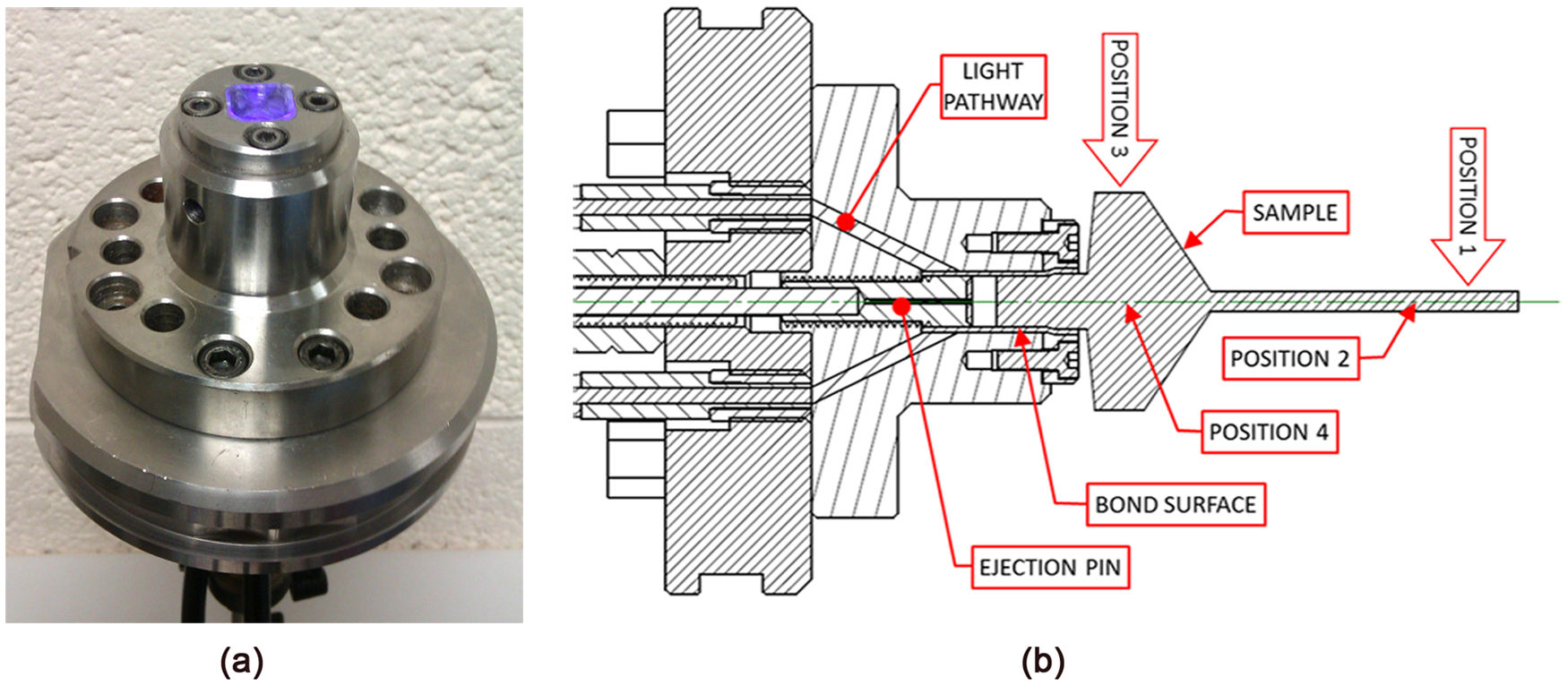
AFS #3 used for holding aerospace component: (a) photograph with UV light on and (b) section view design.
A substantial advantage of the AFS was that it allowed the irregular shaped, widely toleranced, component to be held in the correct position, on reference points, during the curing process. This would not have been possible if the component was simply mechanically clamped. In order to eject the component, an ejection pin advances breaking the adhesive bond after processing and scrapes any residual adhesive from the fixture removing the need for cleaning prior to reuse.
The component was held successfully without failure during all roughing and finishing cuts. The adhesive joint withstood peak resultant (FR) forces of 2800 N (position 1), 1050 N (position 2), 850 N (position 3), and 450 N (position 4) as recorded during the roughing cuts. The Fx force as shown in Figure 17 exceeded the range of +2000 to −2000 N. Of particular interest were cuts performed at the end of the component where the stiffness was minimum (positions 1 and 2), a highly cyclic loading condition producing an interrupted contact between the workpiece and grinding wheel. Cuts taken on the more rigid part of the workpiece (positions 3 and 4) produced a force profile more akin to the previous results (Figure 15) of grinding, that is, dominated by the statically applied load induced during the cut. These VIPER grinding trials revealed that the AFS was capable of withstanding high levels of dynamic cutting forces on low stiffness parts held in very demanding set-ups (i.e. cantilever), proving the very scope of this fixturing solution, that is, increased access on machined surfaces so that part repositioning can be avoided.
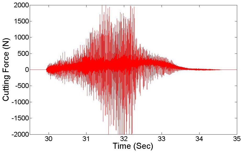
Fx force for one roughing pass (ap = 2 mm).
Dynamic response evaluation of AFS through impact hammer tests
To better understand the influence of the bond on the dynamic response of the component fixture system, impact hammer tests were conducted with two set-ups tested for comparison: (1) with AFS system and (2) using a commercially available mechanical holding fixture system (Erowa 032785). Drive point frequency response function (FRF) was acquired at the most flexible location (position 1 in Figure 16) of the parts. From Figure 18(a), it can be seen that the amplitude of vibration in terms of acceleration is significantly reduced for the component held with adhesive (blue colour curve). The reduction can be noticed for all modes. Also, a shift in natural frequencies to the left side is noticed. Generally, for stiffer holding of the component, an increase in natural frequency is expected. From the amplitude of curves in Figure 18(b), which is a receptance form of FRF, it can be seen that the adhesive joint has a lower compliance compared to that of the mechanical joint (4.5 µm/N compared to 7.5 µm/N). Hence, it is inferred that the adhesive provided an ideally strong bond between the component and the holding fixture, and this acts as an addition of mass to the component stem and the holding fixture and consequently lowers the natural frequency of the component (
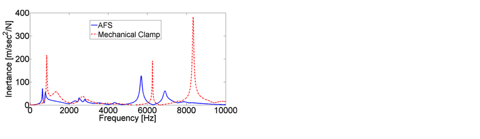
Comparison of dynamic response of workpiece held in AFS #3 and mechanical clamp: (a) inertance and (b) receptance form of FRF.
One more feature that can be noticed is that the peaks in the adhesive joint FRF curve are wider (between half power points) indicating better damping being provided when compared to a bolted joint; this will aid in absorption of machining-induced vibrations. The reduction in maximum vibration amplitude and also increase in damping of machining vibrations ensure a component with less form errors during machining.
Conclusion
The need for more versatile fixturing systems, for increasingly complex components, necessitates innovative design of fixturing solutions to enable increased access to machining surfaces with minimum part repositioning. In this context, adhesive fixtures seem to be a viable solution as they enable quick and stiff holding on reduced holding surfaces.
Apart from proving the validity of the design of a new fixture (AFS), the article brings to the attention of the fixturing specialist an overview (Table 1) of the capabilities of the adhesive joints that will be able to support such designs.
Summarised performances of AFS versus benchmark fixturing solutions.
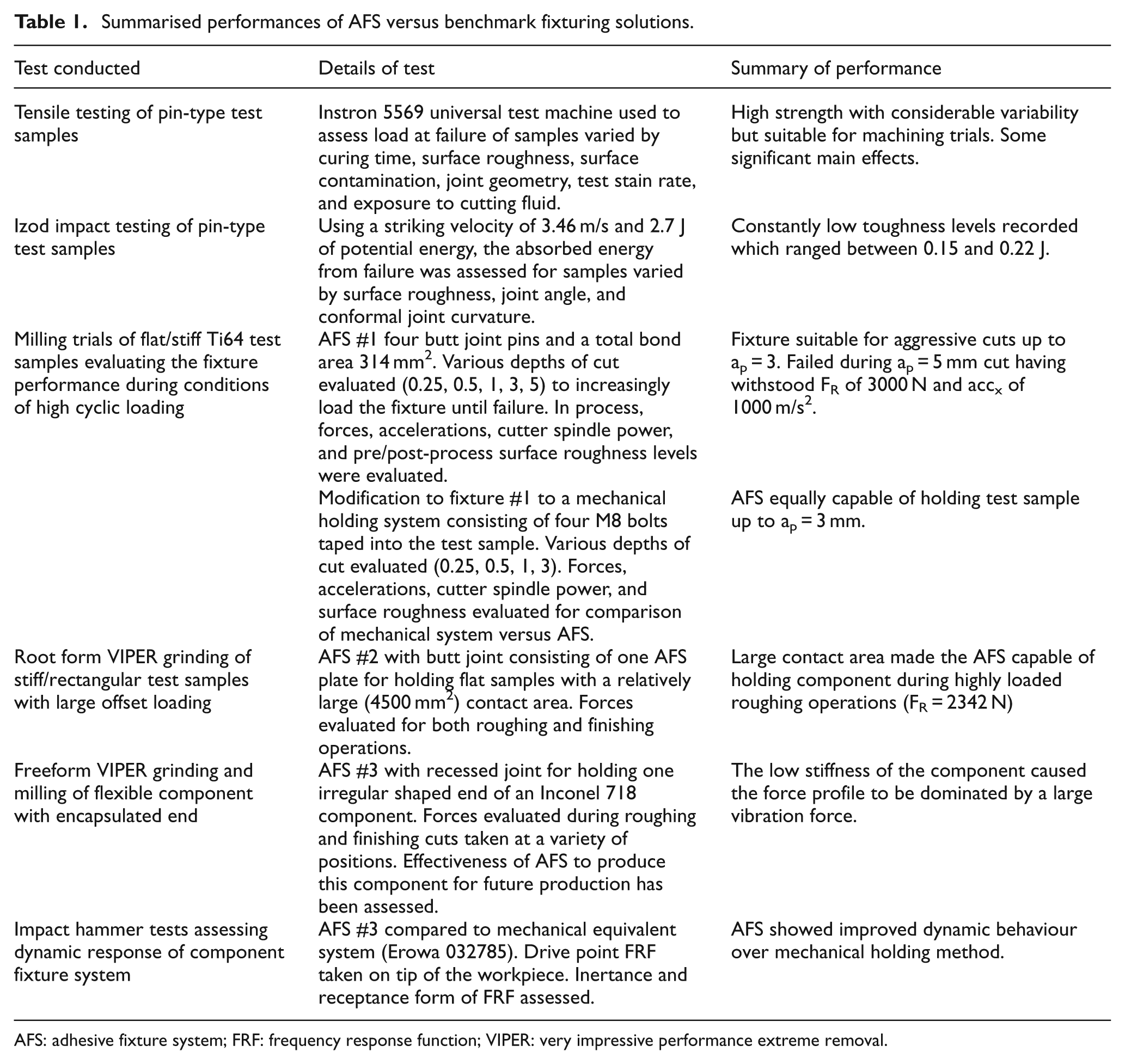
AFS: adhesive fixture system; FRF: frequency response function; VIPER: very impressive performance extreme removal.
Therefore, the main findings of the article can be concluded in the following novel aspect:
New design concepts for the bonding of the parts to the fixture in such a way that reduces mechanical stresses incurred on the part; this is of particular importance when machining components with reduced stiffness such as those used within the aerospace industry.
Documented analysis on the bond strength in relation to influential factors related to real machining operations is presented. This included contamination, surface roughness, cure time, and joint geometry. This is of particular importance for the machining community which will accept this kind of fixture only when the real production requirements are addressed.
The proposed design solutions of AFSs have been thoroughly evaluated in machining operations detailing the level of machining forces that these fixtures can withstand. It was demonstrated that high loading, created during aggressive machining operations such as VIPER grinding, can be withstood even when held in a cantilever mode with a large overhang. The AFSs demonstrated a high load transfer capability for machining operations that generate maintained static and cyclic loadings. The magnitude of the machining loads withstood, 2800 N, goes far beyond the necessities of industry for the particular alloys tested. It also showed an improvement in dynamic behaviour of the held workpiece over more conventional mechanical fixturing, with dynamic stiffness increased by 67% in addition to providing improvement in damping characteristics.
Although this is a preliminary investigation of a novel fixturing method, the article proves the validity of this approach especially when machining complex components that require maximum accessibility; it is here where the main benefits of the system can be observed.
Footnotes
Acknowledgements
This work has been carried out with the help of Rolls-Royce plc. The authors would like to thank Mr Peter Winton of Rolls-Royce and Mr Mark Daine of the University of Nottingham for their continued support and encouragement.