
Abstract
The task of setup planning is to determine the number and sequence of setups and the machining features or operations in each setup. Due to the locating method’s character, the position of the locators may keep away joining tools from arriving at joining points during the joining process of sheet metal. In order to solve these problems, a novel method is proposed, which consists of three parts: (1) the points on the skin are divided into sets of supplied riveting and prior riveting points by convex hull generating method; (2) fixture vector is defined, and a suitable fixture region is generated by vector multiplication; and (3) the particle swarm optimization algorithm is applied to generate optimal setup scheme by setting up the parameters. The new setup planning approach can accomplish riveting work by minimum setup times and workpiece variation without finite element analysis software. At last, a certain kind of aircraft wing joining process is illustrated as an example to demonstrate the effect of the proposed approach.
Keywords
Introduction
Standard computer-aided design (CAD) and computer-aided manufacturing (CAM) tools are now used by industrial organizations to reduce the time and costs of product design and manufacture. It is well known that there is a functional gap between CAD and CAM, which could be bridged by computer-aided process planning (CAPP) only. 1
Setup planning is one of the most important and complex steps in CAPP, which may have a strong impact on manufacturability, total time, and production cost. It has been reported that about 20%–60% machining error is brought by the setup process. 2 In the aviation, aerospace, and automobile industries, a typical workpiece (such as panel and frame) has the characteristics of large profile and low stiffness, which is susceptible to deformation during the setup and joining process. In this regard, there is a need for the setup planning to feature more locators and clamping devices to maintain the surface. The position distributing and changes of these locators and clamping devices are related to the efficiency and accuracy of the joining assembly work.
Taking panel assembly, for example, the skin and stringer are joined by automatic drilling/riveting system, and the skin is located and clamped on the bracket system as shown in Figure 1. The skin is located by several supporting plates that have the same surface in the contact area such that the position on the skin is in one-to-one correspondence with the supporting plate. When the supporting position on the skin is changed, the supporting plate needs to be taken off and replaced by another corresponding plate. As the positions of the supporting plates change continually throughout the joining process, there is a need to factor this dynamism in the setup planning.
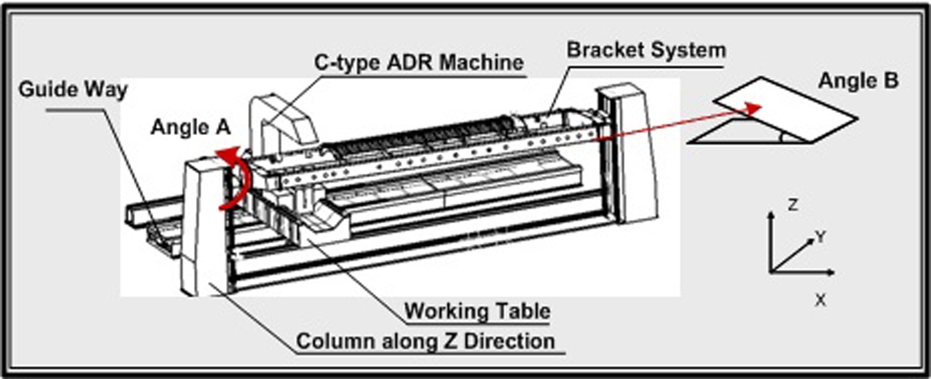
Automatic drilling/riveting system.
Previous works in the field highlight three methodical approaches: graph theory, knowledge engineering, and intelligent algorithm. Graph theory and knowledge engineering are useful tools for setup and fixture planning. Zhang et al. 3 proposed a hybrid graph approach, which can be transferred into directed graph, and tolerance relations are used as critical constraints. Lately, an extended graph describing a feature and tolerance relationship graph (FTG) and a datum and machining feature relationship graph (DMG) were used to support an automobile manufacturing enterprise in fixture design and production planning. 4 Sun et al. 5 proposed a new directed graph approach, which could generate many optimal or near-optimal setup plans and provide more flexibility required by different job shops.
More attention is given to intelligence algorithm.6–8 Ong et al. 9 presented a concurrent constraint planning methodology and a hybrid genetic algorithm (GA) and simulated annealing (SA) approach for setup planning, and resetup planning in a dynamic workshop environment. Lee et al. 10 used Petri nets as a unified framework for representing both operation planning knowledge and process sequence. Cai et al. 11 presented a cross-machine setup planning approach using GAs for machines with different configurations. Alluru and Rao 12 present an application of a newly developed metaheuristic called the ant colony algorithm as a global search technique for the quick identification of the optimal operation sequence by considering various feasibility constrains. Chen et al. 13 report a new approach to setup planning of prismatic parts using Hopfield neural net coupled with SA.
Some researches have taken tolerance specifications into account. Zhang et al. 14 proposed a graphical approach to generate optimal setup plans based on design tolerance specifications. Bansal et al. 15 developed an integrated setup and fixture planning system for minimizing tolerances at critical regions using a data exchanged part model as an input. Huang and Liu 16 provided a tolerance normalization approach for direct comparison of different types of geometric tolerances and dimensional tolerances. Yao and Han 17 developed an automated setup planning technique and system based not only on the tolerance analysis but also the manufacturing resource capability analysis. Kang et al. 18 presented a new approach for fixture tolerance analysis that is more generalized and can be used to assign locator tolerances based on machining surface tolerance requirements.
All these methods provide a strong basis for setup planning. However, the main problem of knowledge-based and graph-based approaches is that there is no consideration with the precedence constraints during setup formation. The constraint of tolerance cannot be neglected for product quality. On the other hand, due to the demand of supplied riveting, the problem in this study is a special dynamic planning that needs to find a new approach to solve the problem. Intelligence algorithm can be applied to accelerate planning.
In summary, there are three aspects to this problem that have to be addressed. The first problem relating to the layout of supporting plates is whether all the joining points could be riveted. The second aspect deals with the variation of the workpiece, which may impact the position accuracy of the joining points on the skin. The third question involves locating times that are intimately related to assembly efficiency. Based on the review, setup planning for sheet metal assembly needs to consider compliment rates, locating times, and the variation of the workpiece.
In this article, a new setup planning method is proposed on the basis of the supplementary riveting (SR) region definition. First, the points around fixtures are divided into sets of Supplied Riveting (SR) and Prior Riveting (PR) points using convex hull. Because the joining tools are obstructed by supporting plates, clamps, or other fixed components, points in SR sets cannot be riveted. In CSR sets, the points can be riveted preferentially. Second, the fixture vector is defined and a suitable fixture region is generated by vector multiplication. Besides, moving steps
Principles and constraints for setup planning
The research of fixture method is not only applied to part machining field but also is used in product assembly process widely. Generally, the relative position among subassemblies is fixed by locators and temporary connectors, which might have the property of disassembly and recycling, such as bolts. Then, the subassemblies are connected by riveting or welding technology. So the fixture may prevent welding gun or riveting hammer from the position of joining points and affect assembling efficiency.
The positioning method of sheet metal is different from the box-shaped workpiece. For box-shaped workpiece, the most general method is the “3-2-1” positioning criterion proposed by Asada in 1985. 19 By selecting three mutually perpendicular planes, the foundation of “3-2-1” positioning criterion is established, which is composed of principal reference, secondary reference, and third reference, as shown in Figure 2. The important surface of the workpiece may be generally selected as principal datum. The criterion constrains six freedoms of the workpiece and considers the requirement of design and assembly simultaneously.
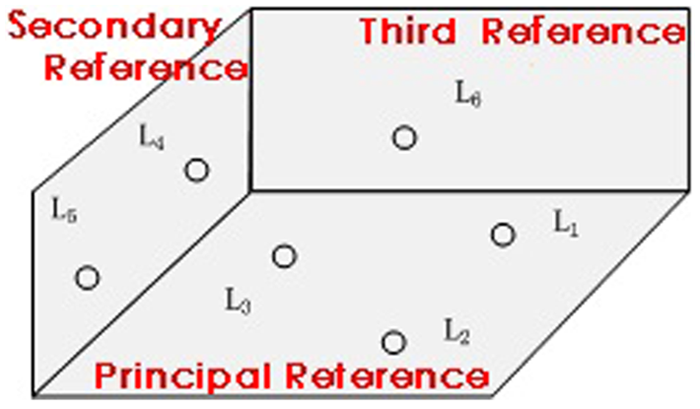
Three reference.
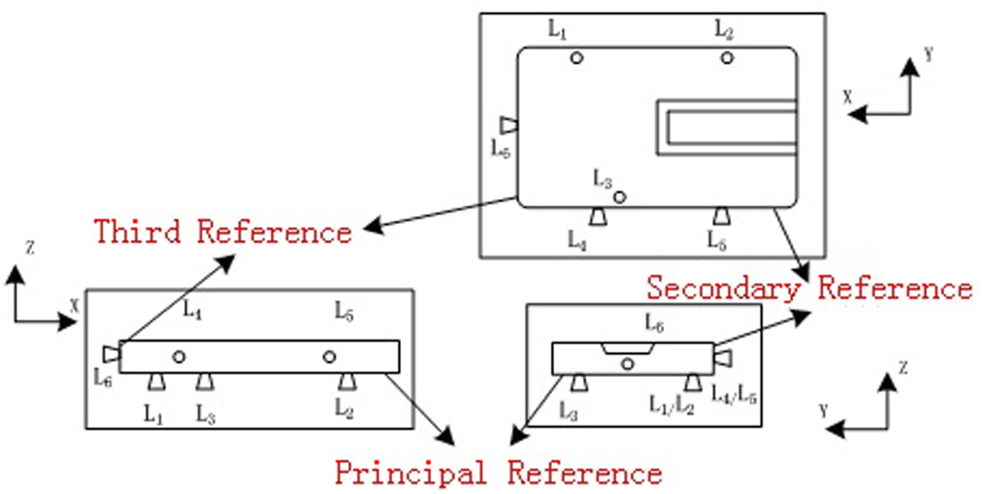
“3-2-1” positioning principle.
According to Fig. 2, plane A is the principal reference, and the locators lie on the characters that can be represented as L1, L2 and L3, which control a translation T z along Z axis and two rotation R x and R y around X and Y axis respectively. Then plane B is selected as secondary reference, and two locators lie on the character L4 and L5. So the translation Ty along y axis and rotation Rz around z axis are controlled. Finally, the third reference C is defined by character L6, and translation Tx along X axis is constrained. Through controlling the three planes A, B and C the workpiece is constrained completely[18].
For sheet metal, the demand must be improved. On one hand, in aviation industry, sheet metal is generally used for the skin in wall panel of the wing and fuselage, which is made of aluminum alloy, and the curvature is one of the most important parameter for aerodynamic performance. On the other hand, due to the material and the structure, sheet metal has the character of low stiffness. Thus, the curvature may be deformed during assembly process for the reason of clamping and joining forces.
Therefore, during assembly process, clamping needs to achieve two aims: one is to maintain the profile of workpiece, and the other is to protect workpiece and frock from relative movement when joining force is applied to the workpiece. In the principal datum, the number of locators may be hard to satisfy this requirement. So the “N-2-1” positioning criterion for sheet metal can be adopted.
It means that N locators are used for positioning and supporting the workpiece in principle reference. The workpiece is in an overconstraint condition. The positioning scheme of the skin is shown in Figure 4, which is also used in other sheet metal assembly positioning.
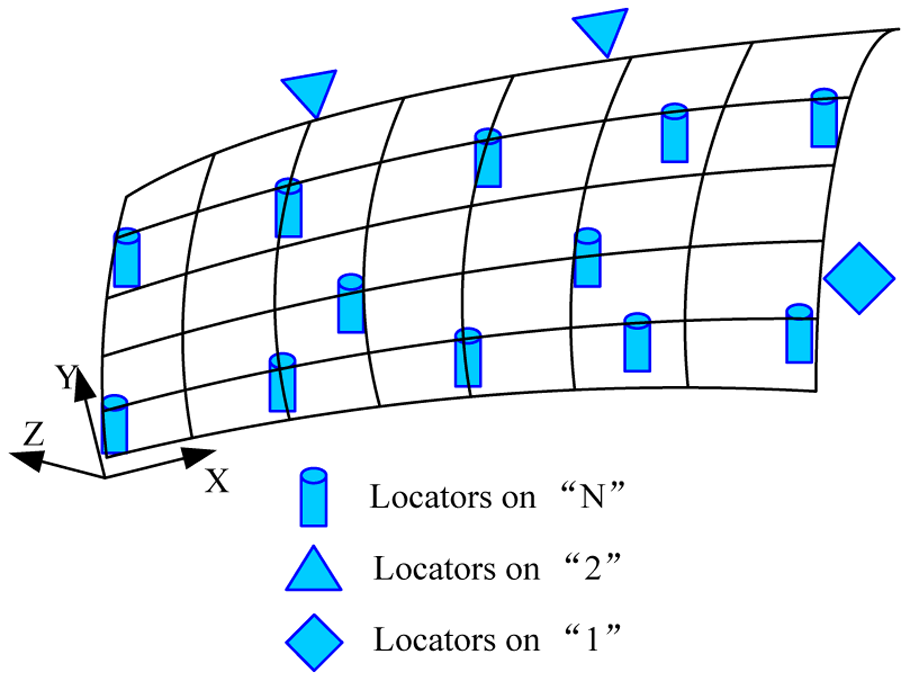
“N-2-1” positioning criterion of sheet metal joining.
After positioning the sheet metal completely, the clamping operation can be carried out. For reducing the clamping deformation, the clamping force can be applied on the symmetric position of the locators. The direction of supporting force is contrary to that of clamping force. So, it is important to pay special attention to the position distribution of the locators. By setup planning, the position of joining points can be assured to lie on the ideal positions, which assures that the assembly work will be launched smoothly.
Setup planning method
For maintaining the surface of skin, N locators are scattered on the surface of the workpiece, which may separate joining tools from the joining points with the position of the locators. So the target of setup planning is to accomplish riveting work by minimum setup times and minimum variation of the workpiece. The method is represented as follows.
Segment definition for fixture
Clamping force acts on the feature surface of the workpiece generally. For some features, such as chamfers and circular conical surfaces, it is difficult to load force and moment. So segments suitable for fixture need to be defined.
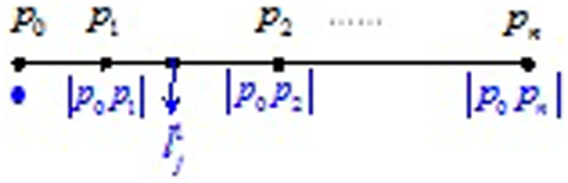
Define the distance of fixture by selecting two points
Then, insert
The vector is defined as

So the segments
SR region division
Suppose there are
Definition 1
It means when the skin is clamped by oth time,
The distance

Given the position of locators and the distance
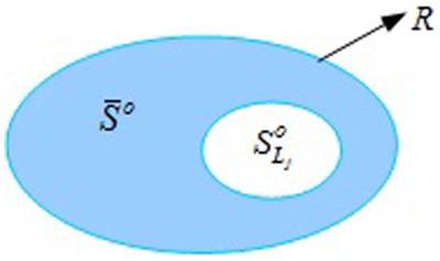
Complementary set
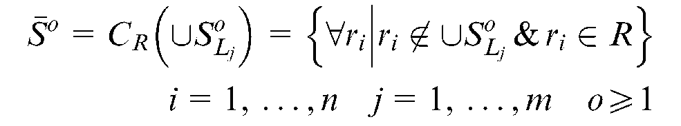
Definition 2
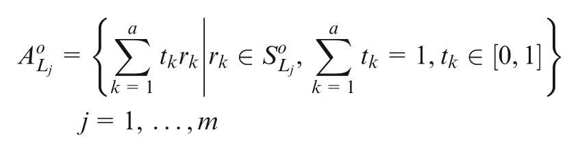
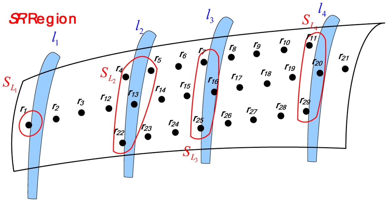
Region
Through the definition, the surface of the skin is divided into multiple regions. As shown in Figure 6, riveting points complementally exist in
There are generally several setups in an assembly process. For each setup, some of the locators have fixed position, and others may be moved. The fixed ones can be checked for interference with joining tools. The moving ones are the key research objects in this article that may impact the times of setup, and it is known as supporting plate generally for skin of aircraft.
Setup planning based on SR region
For the dynamic fixture problem, the most important thing is to find the initial position of the supporting plate, which may impact the number of supplied riveting points. When a workpiece is set up at the beginning, the times of the setup must be considered, which may lead to the increase of deformation rate, and reduce efficiency and accuracy of the product ultimately. So the setup planning method based on the
First, record the initial position of the supporting plate. Let the position of
Initial position of supporting plate.
Second, the two endpoints of supporting plate are moved by step lengths
Third, give the distance
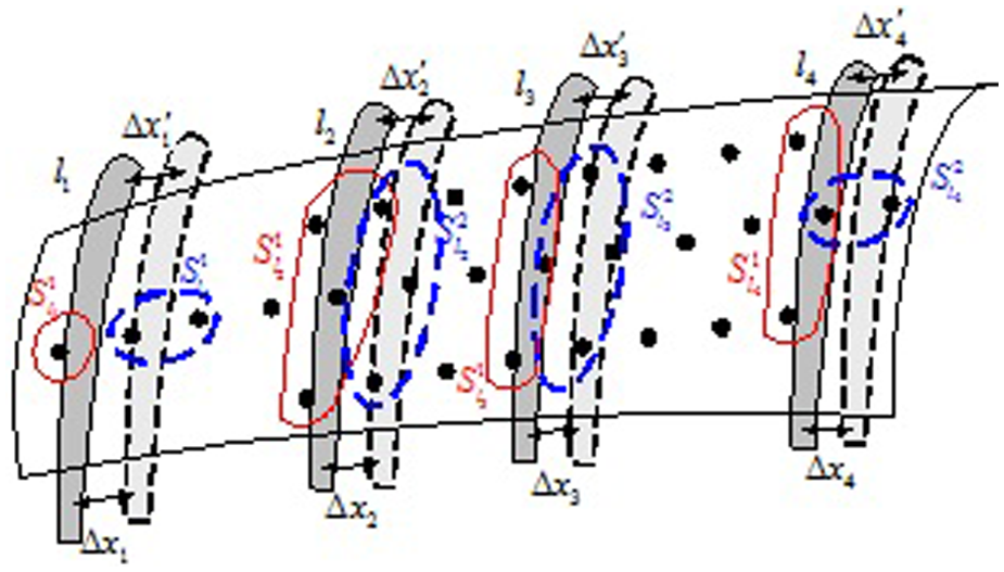
SR set generation.
We can obtain the union,
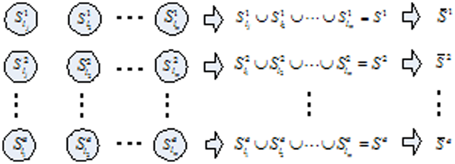
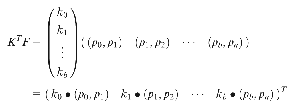
Generation method of
Finally, the question is transformed into a combinatorial optimization problem. The constraint condition is that all the points can be riveted. The PSO algorithm is proposed to generate optimal fixture planning.
The PSO algorithm is an evolutionary computation method introduced by Kennedy and Eberhart.
20
The velocity is constantly updated according to the particle’s own experience and the experience of the whole group of particles. The best experiences of the particle itself and its neighbors are memorized for updating the velocity and position. For finding the optimal solution, each particle

where
With the updated velocity, the position of each particle is updated with the following equation

where
The fitness function is constructed as follows

where


where D is the maximum distance between the two supporting points. D′ is the farthest distance between the rivet point and the clamping point, and n′ is the number in the PR set.

where n is the total number of riveting points on the skin.
The number of particles is related to the searching time and the solution quality. The detailed steps are expressed in the following flowchart (Figure 10).
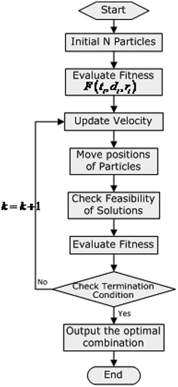
The algorithm flowchart.
This setup planning method can help engineers find the appropriate initial position of supporting plates rapidly; it only needs input of some parameters. The optimal output includes the position of every supporting plate and the times of setup.
Example
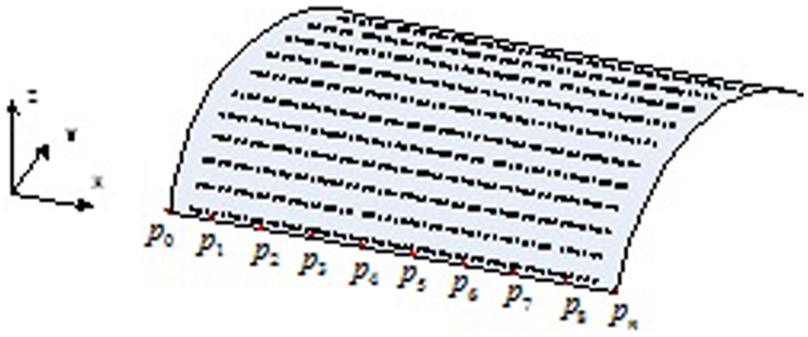
In order to demonstrate the effectiveness and robustness of the setup planning method, a wing panel is chosen as an example, which is made up of a skin and 11 stringers. The CAD model of the skin is shown in Figure 11.

A panel model.
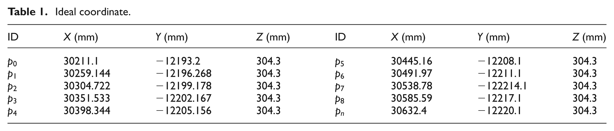
Ideal coordinate.
Define a vector
The six intervals
Panel with fixture intervals.
Distance definition.
The distance between
Initial position of supporting plates.
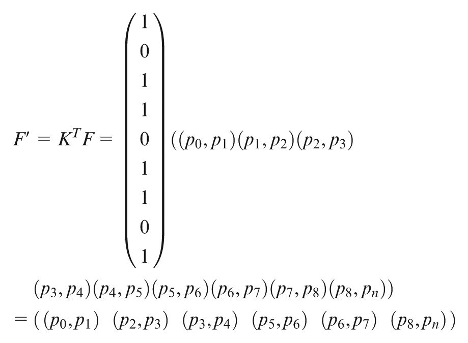
Define
The left riveting points are put into
Let these conditions be the input conditions. Set up initial parameters
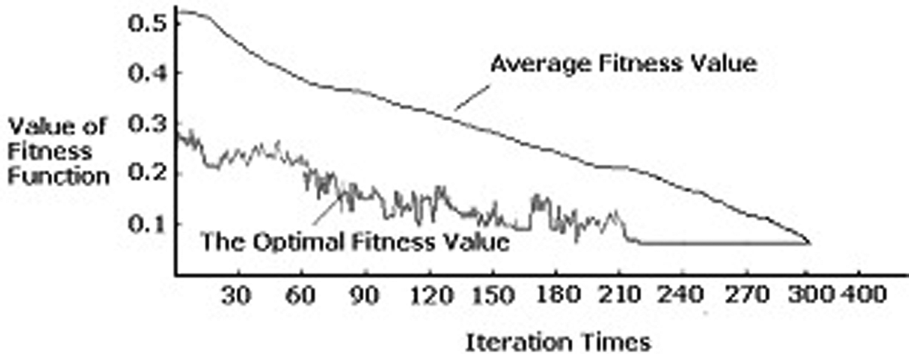
Optimal fitness function value.
By running the PSO optimization program, the setup scheme has been outputted. By setting up twice, all the points are riveted, as shown in Figure 16.
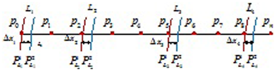
Setup scheme.
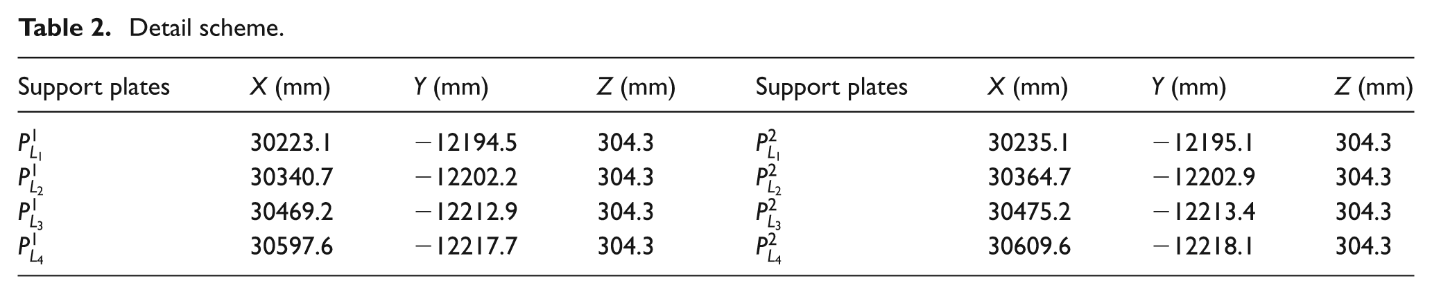
The setup schemes are shown in Table 2. The times of setup accords with the practical situation, and the detailed position can be applied to the assembly process directly.
Detail scheme.
Conclusion
A novel setup planning method aimed at the problems in the assembly of sheet metal is proposed, which can solve dynamic planning problem of supporting points or clamping points, considering the variation radio of workpiece and the riveting radio at the same time. Especially for sheet metal, the number of supporting points is more than in the other parts for maintaining the surface, and the position is dynamic, which needs to change in the process of joining assembly for avoiding blocking the joining tools. The PSO algorithm is used to improve calculation efficiency of the combinatorial optimization.
This method also can extend to setup planning for other types of locators, by modification of the coverage of d. In addition, the method can be used for situation optimization of fixture points without finite element analysis (FEA) software. Future work will consider a more accurate expression of the workpiece variation, and will also need the addition of clamping force to the setup planning.
Footnotes
Acknowledgements
We would like to thank the editors and the anonymous referees for their insightful comments.
Funding
This study was supported by National Natural Science Foundation of China (50805119), Aeronautical Science Foundation of China (2010ZE53030), and the Foundation for Basic Research of Northwestern Polytechnical University, China (JC201032).