
Abstract
Tube spinning, without mandrel, is a common process used for manufacturing pressure vessels, e.g. CNG (Compressed Natural Gas) capsules for automotive industry and fire extinguishers. The process is carried out at an elevated temperature for forming a dome on thick wall steel tube ends. Two of the most important control parameters in the process are the “roller contact start point” (RCSP) and spinning feed (pitch), both of them highly affecting the process time and deformation behavior of the tubes and therefore success and quality of the product. In this article, using a three-dimensional dynamic explicit finite element model, the effects of these parameters are investigated on circumferential, axial and radial (thickness) strains of the formed tube in three thickness layers of the tube wall. The model is also verified by experiment.
While circumferential strain is shown to be independent of the feed, axial and thickness strains are highly affected by both the feed and roller contact start point. It is shown that when the roller contact start point distance from the free end of the tube increases, there is a risk of indentation instead of normal bending behavior. It is also shown that axial strain has an inverse relation with feed, i.e. decreasing the feed results in further elongation of the tube. On the other hand, thickness strain increases by increasing the feed, so bigger thicknesses are expected in domes manufactured by higher feeds. In addition, it is shown that increasing the feed results in a decrease of the equivalent strain. The amount of residual stress (regardless of the temperature change) increases with increasing feed and its distribution is more uniform for higher distances of the contact start point from the free end.
Keywords
Introduction
Tube spinning is a widely used method for dome forming on tube ends used for fabricating CNG steel capsules and aluminum liners of the composite capsules. The process is categorized as one of the various spinning procedures in which there is no mandrel or die. Some recent articles on general spinning and flow forming processes include the works of Razani et al. 1 on the experimental study of flow forming of steel tubes, Wang et al. 2 on the study of the effect of roller feed on wrinkling in conventional spinning and works of Fan et al. 3 on the investigation of a novel flanging method by spinning.
Although there have been extensive experimental, analytical and numerical studies on spinning procedures, tube spinning and dome forming lacks in-depth studies and there are only limited articles published in this field. Jianguo and Makoto carried out an experimental research on paraxial spinning on aluminum tube ends. 4 They have investigated the effect of spinning pitch (axial feed) and diameter reduction on several quality and process factors, e.g. thickness strain, spinning forces, twisting angle and surface roughness. In two other similar researches, they carried out experiments to investigate the same parameters in necking of the middle of aluminum tubes 5 and forming tapers on tube ends. 6 Yoshihara et al. discussed the finite element (FE) modeling of the spin forming of magnesium alloy tubes and investigated the differences of deformation depending upon variation of spinning paths. 7 Akkus and Kawahara presented an analytical method for interpreting the thickness distribution of the dome at the tube end. 8 Their experiment was also carried out on aluminum tubes. Lexian and Dariani presented an analytical formulation for modeling the contact in FE simulation of the dome-forming spinning of steel tubes. 9 The same authors in another article investigated the effect of roller nose radius and release angle on spinning quality of the steel tubes. 10 Huang et al. developed a FE model using ABAQUS software considering the thermal effects on material properties and also investigated several parameters, e.g. roller nose radius, friction coefficient and roller translational speed on the spinning of steel tubes. 11
In this article, considering the experimentally obtained effects of high temperature and strain rate on material behavior, the effect of feed (spinning pitch) and roller contact start point (RCSP) is investigated on accumulated strain and residual stress distribution, using a FE simulation supported by experiment.
Modeling and experiment procedure
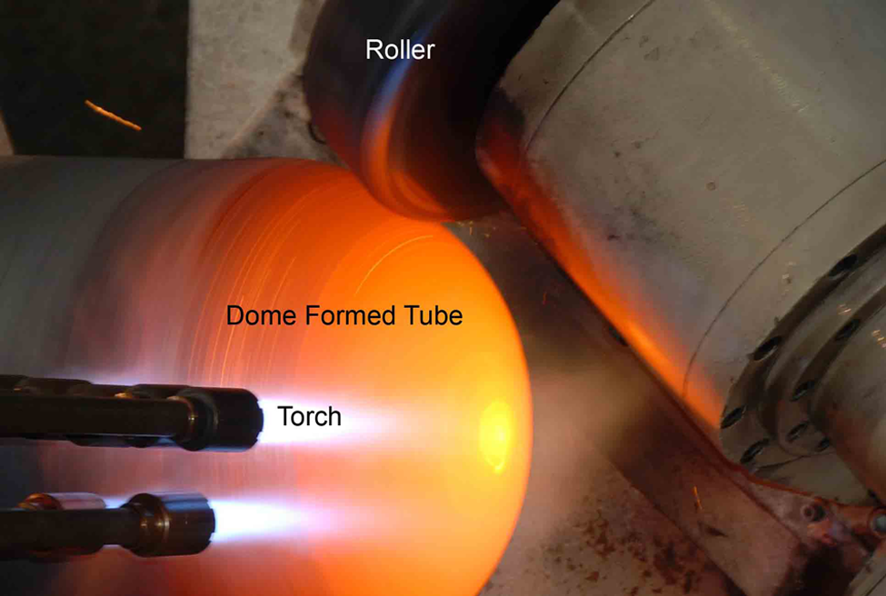
Figure 1(a) shows the dimensions of the tube and forming roller and their interaction in the process, in the experimental set-up the tube end is completely shaped into a dome (shown in Figure 1(b)) in eight passes schematically illustrated in Figure 1(c). Each pass starts from a more distant axial location from the free end compared with the prior pass. The final pass starts nearly from the location where the hemisphere starts. Figure 1(b) is the dome part of the final workpiece fabricated experimentally in eight passes, which is also cut in axis for measuring its thickness. Figure 2 shows the procedure of hot tube spinning used for manufacturing a dome form on a tube end.
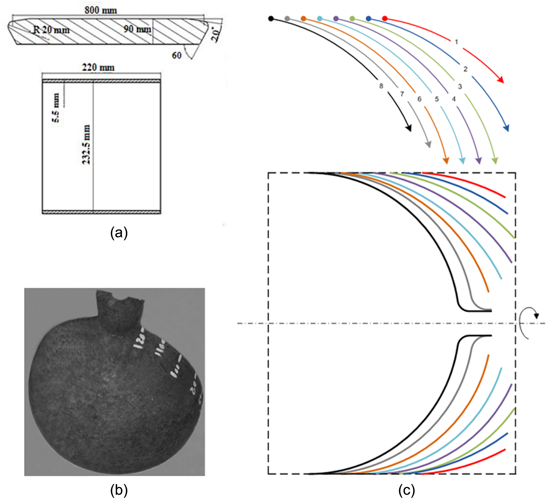
(a) Dimensions of the tube and roller and model configuration; (b) final workpiece fabricated experimentally; (c) spinning paths.
Configuration of the experiment on dome forming.
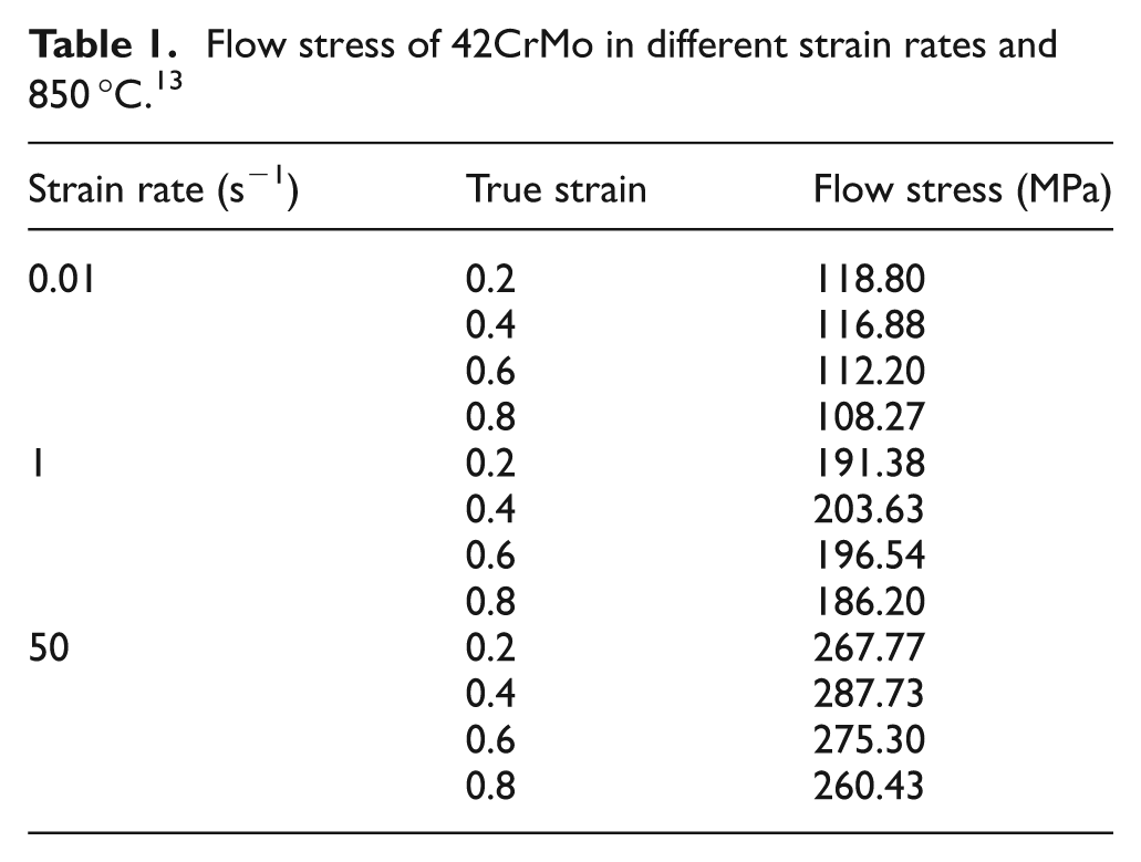
The FE model consists of a tube with 22,400 (four elements in thickness, 160 in circumference and 35 along the axis) cubic solid elements C3D8R, roller and chuck, which are considered as rigid parts in the ABAQUS/computer-aided engineering (CAE) environment. Three-dimensional (3D) dynamic explicit formulation is incorporated and contact is defined as penalty type. Coulomb friction of 0.02 is applied for interaction between the workpiece and roller. The material of the tube in the experiment and FE model is 42CrMo4, and the process is carried out at about 850 °C. Owing to the elevated temperature of the process, material behavior significantly varies from that in standard room temperature. Recovery and dynamic recrystallization arise after a critical strain and induce softening by retrieving the dislocations and reducing their accumulation. 12 Therefore, in a precision numerical analysis it is not proper to use common elastic–perfect plastic or strain hardening governing equations. Furthermore, owing to the use of different spinning pitches, different strain rates are applied to the material. Material behavior modeling, in this article, includes the dynamic softening effect of high temperature and hardening effect of strain rate according to the results of a hot compression test, carried out by Lin et al. 13 During the experiment the tube is heated by several acetylene torches, so that the temperature of the deformation zone is maintained and can be considered as constant.
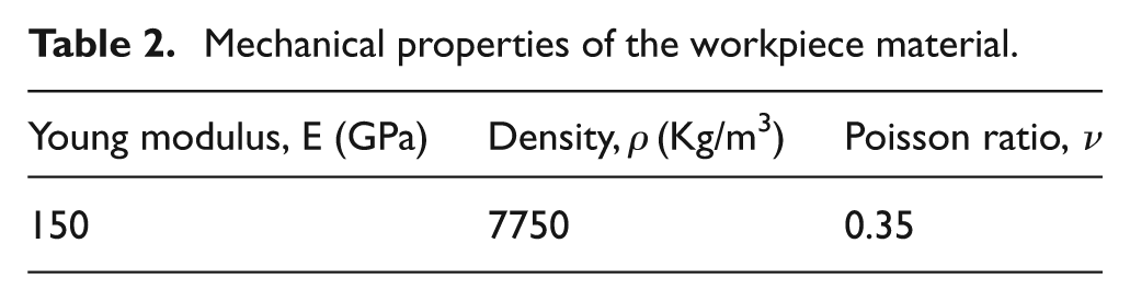
Table 1 shows the values of flow stress in 850 °C for different strain rates. The rest of the material properties are depicted in Table 2.
Flow stress of 42CrMo in different strain rates and 850 °C. 13
Mechanical properties of the workpiece material.
In accordance with the experiment, spindle rotation speed is considered to be equal to 800 r/min. Owing to the long rendering times required to complete the process in eight passes, only one complete (eight pass) render was used for comparison to the final workpiece dimensions, as a validation criterion of the FE model. Owing to the elevated temperature of the process, real-time or even usual offline experimental strain measurement techniques, like marking grid lines on the workpiece, are not possible. Other researchers, including Akkus and Kawahara, 8 Lexian and Dariani9,10 and Huang et al., 11 have also compared the thickness distribution or profile of the fabricated workpiece with the rendered model outcomes for validation purposes.
Figure 3 shows the comparison of the thickness of the final product achieved in an eight spinning pass simulation with the product experimentally shaped with the same parameters (spinning passes, pitch and starting point). It is seen that there is a good agreement between the experiment and simulation and, therefore, geometrical outputs of the model, e.g. strain, can reliably be referred to. The results obtained by Lexian and Dariani 9 are also in good agreement with those shown in Figure 3. However, the study was focused on the first spinning pass, the resultant strains and the effect of starting point and spinning pitch on deformation modes of the tube.
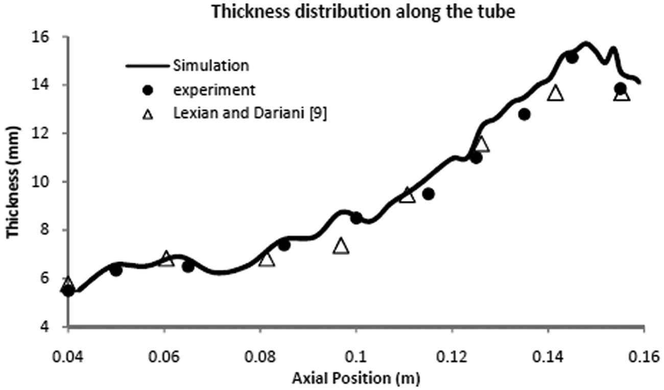
Comparison of final geometry achieved from the FE model with experiment.
For investigation of the effect of spinning pitch and starting point, four pitches (spinning feeds) and four starting points are tested on the model. The tested spinning feeds (P) are 1.5, 2.5, 3.5 and 7.5 mm/rev and the starting point distances (D) from the free end are 30, 40, 50 and 60 mm. The strains in three major directions (circumferential, axial and thickness) and in three thickness layers (inner, middle and outer) are extracted and analyzed for each combination of feed and RCSP.
Considering the nature of the process and spinning passes depicted in Figure 1, using higher pitches and more distant starting points results in lower forming times and, therefore, it is highly desirable for the economics of production. On the other hand, higher pitches and distant starting points may cause some defects, e.g. bad surface quality, forming instability and unwanted deformation modes, which make the control of final product geometry difficult and sometimes impossible. Therefore, one goal in every tube spinning process is the achievement of highest spinning pitch and most distant starting point that certifies the final geometry and surface quality.
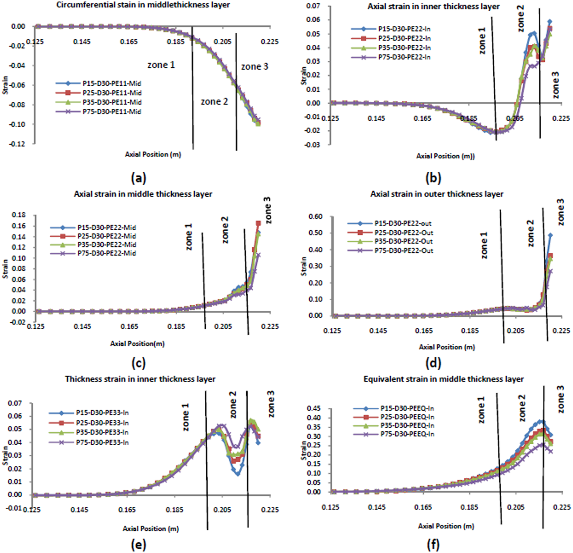
For further convenience, the deformed part of the tube is divided in three major portions. This categorization, along with the distribution of the strain on the deformation zone, is depicted in Figure 4. Zone 1 is the part more distant from the free end of the tube and closer to the chuck, zone 3 is the free end portion and zone 2 is the portion between zone 1 and 3. One should note that changing the RCSP distance from the free end (D) results in a variation of the length of these three zones. In fact the length of zone 2 (L Z2) is equal to 45% of the RCSP distance from the free end and length of zone 3 (L Z3) is equal to 25% of the RCSP distance from the free end.
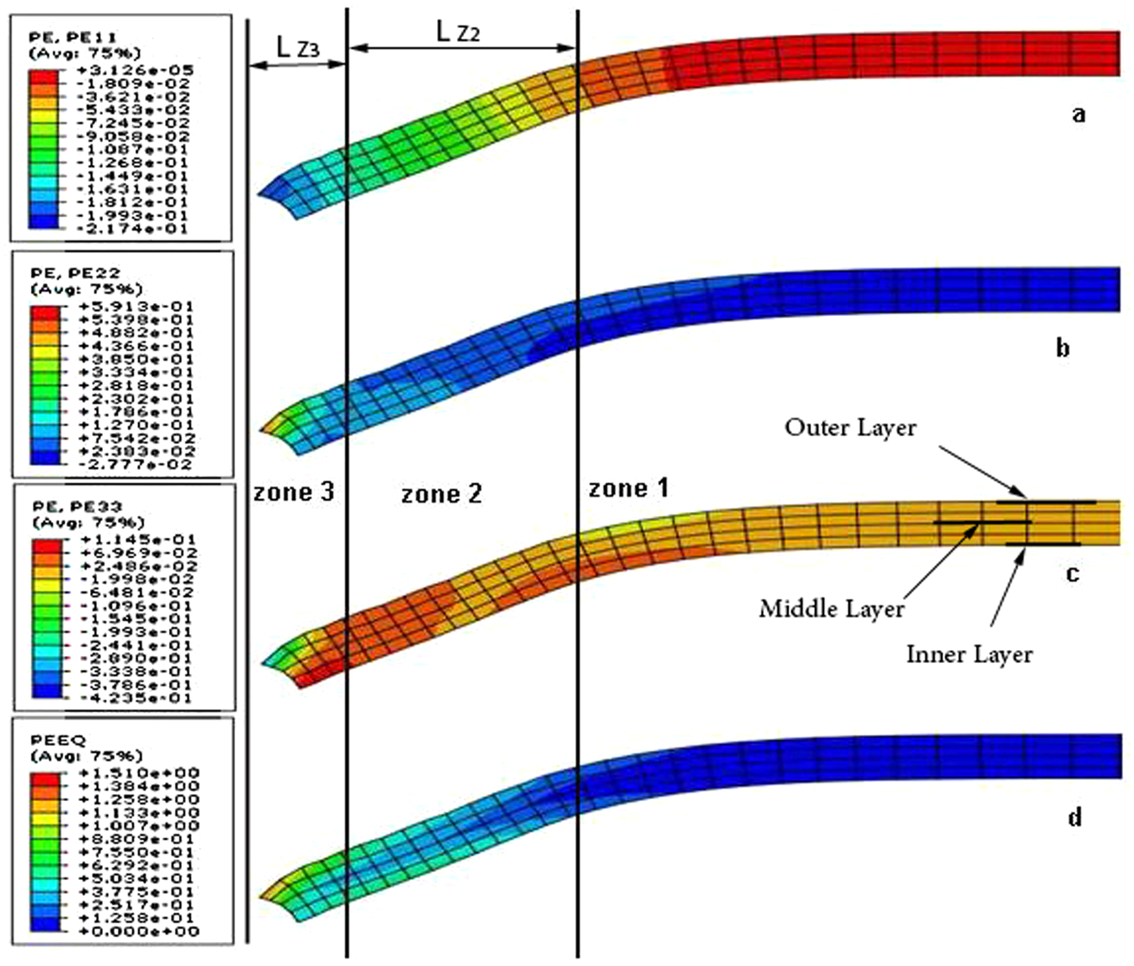
The strain distribution in three different zones of the tube (PE11: circumferential strain; PE22: axial strain; PE33: thickness strain; PEEQ: effective strain).
Results and discussion
Effect of the RCSP distance from the free end on strains
As already discussed, four different starting points are chosen for the process. The strain components, in circumference, along the axis and radial (thickness) directions are studied for different points of the spinning path and in three layers of the thickness, namely inner, middle and outer layer depicted in Figure 4. Figure 5 depicts the variation of the strain components along the tube axis in different thickness layers for different RCSPs. Spinning feed, used to study the RCSP effect for all the diagrams depicted in Figure 5, is equal to 1.5 mm/rev.
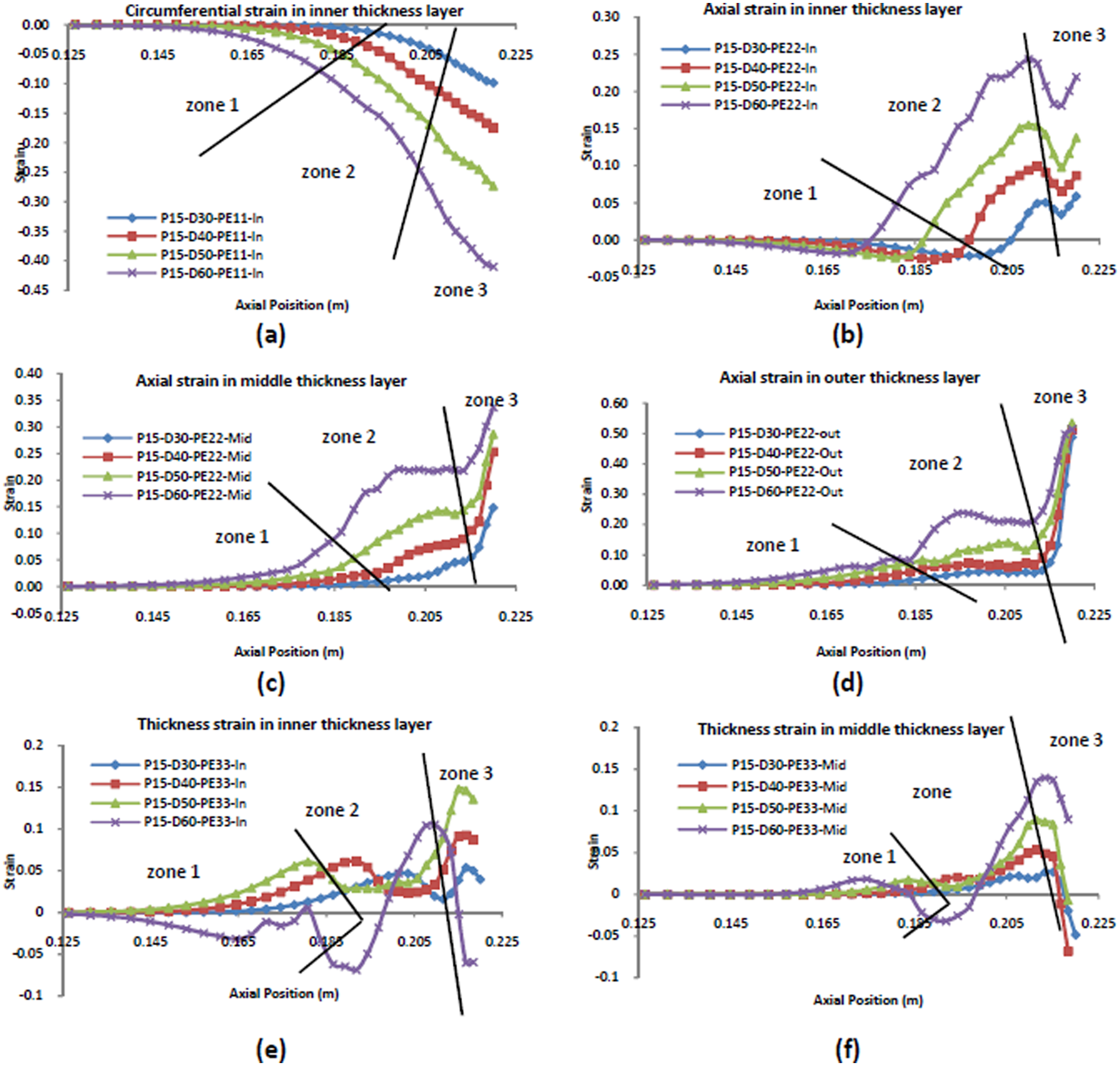
Circumferential strain (a) in the inner thickness layer, axial strain (b) in inner, (c) middle and (d) outer thickness layer, thickness strain (e) in inner and (f) middle thickness layer for different RCSP distances from the free end, D30 denotes RCSP distance from the free end = 30 mm and P15 denotes spinning feed = 1.5 mm/rev.
Effect of the RCSP on circumferential strain
Figure 5(a) shows the circumferential strain in the inner layer for different RCSPs. The same pattern with no distinguishable change exists for the other two (middle and outer) layers. Obviously moving the RCSP to the chuck side from position D = 30 mm (distance from the free end) to D = 60 mm results in a higher compressive circumferential strain, throughout the spinning path and especially at the free end (zone 3).
Effect of the RCSP on axial strain
The axial strain in the inner, middle and outer layer are depicted in Figure 5(b), (c) and (d), respectively.
Figure 5(b) shows that the maximum compressive axial strain in zone 1, in the inner layer, slightly decreases with moving the RCSP towards the chuck. Meanwhile the maximum positive strain, which occurs at an approximately constant position 0.2 (from chuck side) regardless of the RCSP, increases with moving the RCSP towards the chuck. The increase in curve D = 60 compared with the others is nearly twice more.
The dropdown at the position near to the free end in Figure 5(b) is also of interesting nature, indicating the nuance of other deformation modes. It is observed that the position of this local minimum is independent of the RCSP, suggesting that the new deformation mode contribution is related to material constraint decrease in zone 3. Regardless of the RCSP, Lexian and Dariani also observed the increase of the strain at the free end for different roller geometries. 10
In Figure 5(c), the distribution of the axial strain in the middle thickness layer is shown to be of increasing nature towards the end. The significant difference of the D60 curve from the others is easily seen (especially in zone 2). The same condition arises for axial strain in the outer layer, shown in Figure 5(d), where the D60 curve is highly offset from the other curves.
Effect of the RCSP on thickness strain
Figure 5(e) and (f) shows the effect of the RCSP on the thickness strain in, respectively, inner and middle thickness layers of the tube.
In zone 1, the positive strains increase with increasing the RCSP, except for D60 which shows a drop down into the compression area, suggesting the different deformation nature of the D60 from the other curves. This is because of indentation of the roller into the tube. Instead of smooth bending and elongation, the roller indents in the tube and the material piles up in front of the roller. This situation is depicted in Figure 6. The drop down of the thickness strain in zone 3 at the free end is also similar to the observations of other researchers, e.g. Jianguo and Makoto, in an experimental investigation of the taper forming on aluminum tube end. 6
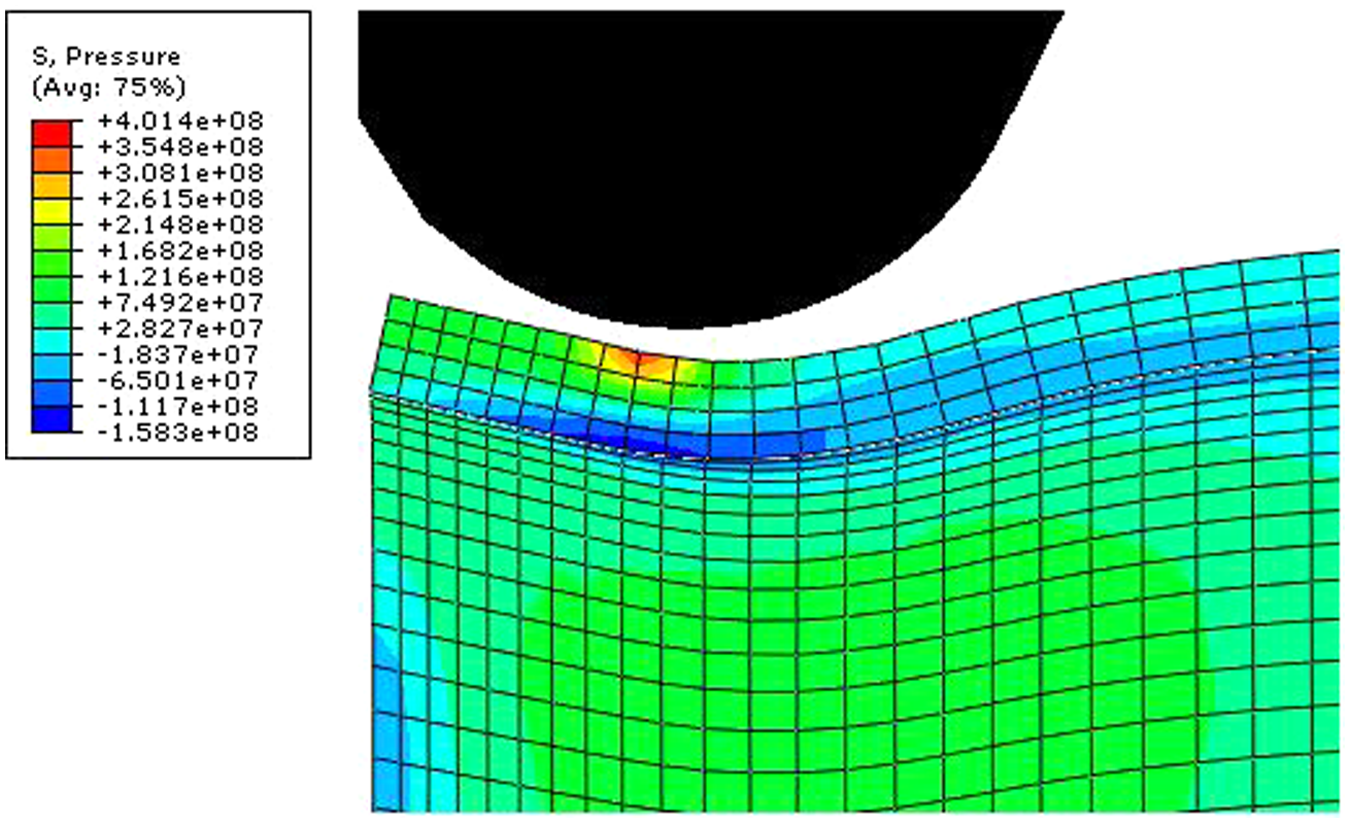
Indentation of the roller into the tube (D60).
Effect of RCSP on residual stress distribution
Figure 7 depicts the Von Mises residual stress distribution along the tube. It is seen that change in RCSP does not have a meaningful effect on stress maxima, at the end of the process. This could be a result of simultaneous increase of strain and strain rate owing to the increase of RCSP distance from the free end, considering that strain rate has an amplifying effect on the flow stress while accumulated strain has decreasing effect on it (because of dynamic recrystallization).
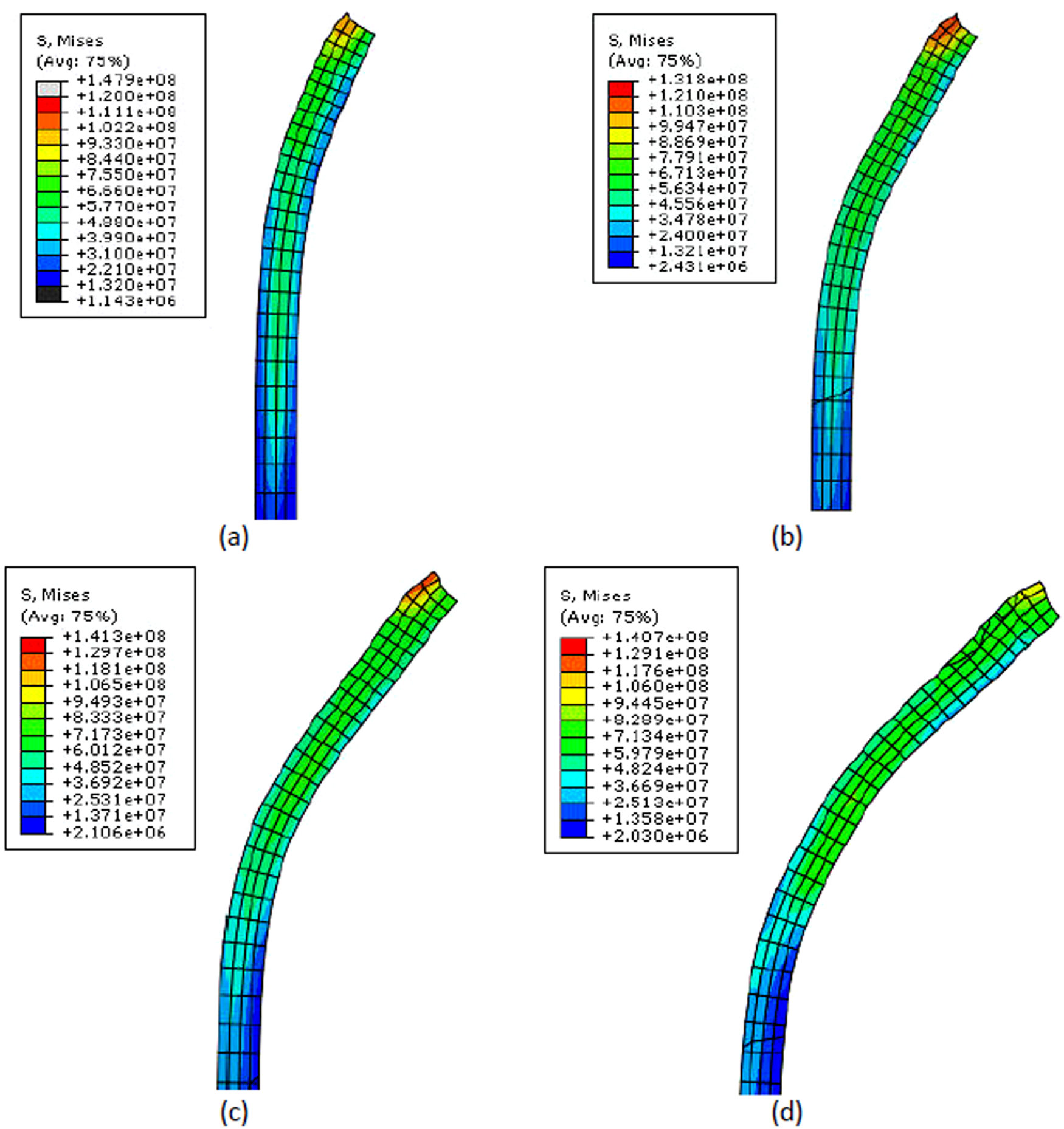
Mises stress distribution for different RCSP distance from the free end = (a) 30, (b) 40, (c) 50, (d) 60.
The meaning of the residual stress in this simulation should not be mistaken with the actual residual stress in the workpiece after cooling down. The temperature and temperature dependent material properties of the workpiece (including flow stress) are constant in this simulation. Therefore, Figure 7 depicts the residual stress of the formed tube after a single pass at the same temperature.
Anyhow, comparing the contour plots of Figure 7(a) to (d) reveals that the length of the stressed zone has increased with increasing the RCSP distances from the free end. Another observable fact is that the relative volume of the material stressed above 70 MPa increases with increasing the RCSP distance from the free end.
It is also seen that the distribution of the stress is more homogeneous in thickness and along the axis at higher RCSP distances from the free end.
Effect of feed (spinning pitch) on strains
The strain distribution in thickness layers for different feeds are plotted in Figure 8 and discussed in this section.
Circumferential strain (a) in middle thickness layer, axial strain (b) in inner, (c) middle and (d) outer thickness layer, thickness strain (e) in inner thickness layer and equivalent strain (f) in middle thickness layer for different feeds, D30 denotes RCSP distance from the free end = 30 mm and P15 denotes spinning feed = 1.5 mm/rev.
Effect of feed on circumferential strain
As well as the RCSP, the studies show that circumferential strain is not affected by variation of the feed. This can clearly be seen in Figure 8(a) for four different values of feed, which has little influence on the amount of strain at the middle layer.
Effect of feed on axial strain
Figure 8(b) shows the effect of feed on axial strain in the inner layer of the thickness. Zone 1 undergoes a compressive increasing strain that is the result of the bending moment applied through the forming roller. In zone 2, contribution of the elongation has caused the axial strain in the inner layer to change direction gradually from compression to tension. Though at the ending portion of this zone there is a dropdown followed by the increase of tensile strain in zone 3, reaching to its maximum at the free end because of the lack of material constraint in the flow path.
It is seen that the increase of feed in zone 1 has slightly resulted in a decrease of compressive strain. In zone 2, there is a local maximum of tensile strain, which is highest for the smallest feed. In other words, the increase of feed has also decreased the strain and its maximum in zone 2. The same condition exists for zone 3; decrease of strain with increase of feed. However, the clearest part of the feeds impact is on zone 2, where the strain values of the different feeds have the biggest difference in comparison with other zones.
Figure 8(c) shows the variation of axial strain because of the change in spinning feed the in middle thickness layer of the tube. The strain characteristics in zone 1, does not resemble the one of Figure 8(b) (inner layer), because the middle zone mostly represents the “neutral axis” in bending, which is not strained, however, pure elongation is observable in this layer, increasing from zone 1 to zone 3.
The increasing rate of the strain at zone 3 is more than that of zone 2 and zone 1 owing to proximity to the free end and lack of material constraint.
Figure 8(d), shows the effect of feed on axial strain in the outer thickness layer of the tube. The main difference with the strain in the middle layer (Figure 8(c)) is that the values in zone 1 are higher than that of zone 2, which is obviously because of the amplifying effect of the bending on the extension in the outer layer. Comparing the strain values in the outer and middle layer, it is seen that the outer layer axial strains possess much higher values, especially in zone 3 and at the free end. This is interpreted as the result of shearing in the axial direction, which can also be noted in Figure 4.
However, in the outer layer, the feed has little effect in zones 1 and 2, while the maximum strain at the outer layer is considerably affected by the feed. The higher feeds result in lower maximum strains at the free end.
Effect of feed on thickness strain
The values of thickness strain for different feeds in the inner layer are shown in Figure 8(e). It is observed that the amounts are small (similar to the amounts of axial strain at the inner layer in Figure 8(b)). Anyhow, in zone 2 the curves are more distant with the curve of highest feed (P75 = 7.5 mm/rev) placed above the others. There exists a local minimum in zone 2 for all feeds, which its axial position is approximately the same where there exists a local maximum for axial strain in the inner layer (Figure 8(b)). The thickness strain pattern (depicted in Figure 8(e)) in zone 2 is in agreement with the results of Zhan et al. 14 In a study on the effect of feed rate on cone spinning, 14 they have shown that increasing the feed results in an increase of thickness. Jianguo and Makoto also have shown the same effect of feed (increase of thickness with increase of feed) in parallel spinning.4,5 In another study where they have investigated the cone forming, 6 though they have observed a thickness reduction from the chuck side to the end, still they have shown that higher feeds result in less thickness reduction.
Figure 8(f) depicts the equivalent strain variation in the inner layer, owing to the variation of feed. The amounts of equivalent strain depicted in Figure 8(f) are also in agreement with the contour plots presented by Lexian and Dariani 9 achieved from a shell element simulation.
Obviously, the deformation and therefore equivalent strain increases towards the end. The dropdown in the free end in zone 3 is a result of the decrease in thickness strain and axial tensile strain in comparison with those of zone 2 in the middle layer. However, it is clearly seen that the lower the feed, the higher is the equivalent strain.
This is thought to be owing to the increase of brushed contact area of the roller with the tube in lower feeds. This is schematically depicted in Figure 9. The total contact area between the roller and tube increases with reducing the feed. Wong et al. have also encountered a similar phenomenon in a study on incremental (rotary) forming of a solid component, where they had seen that higher axial forces are obtained in lower feeds. 15 In their case, the reduction of contact area between the roller and workpiece causes the material to escape from beneath the roller.

Schematic illustration of feed effect in brushed roller contact area with the tube: (a) low feed; (b) high feed).
Effect of feed on residual stress distribution
Figure 10 shows the distribution of the Mises stress along the tube axis and in thickness for different feeds, namely 1.5, 2.5, 5.0 and 7.5 mm/rev. It is seen that the amount of maximum stress slightly increases with increasing the feed. This is the result of higher flow stress of the material in higher strain rates. It can also be seen by observing the data from Table 1.
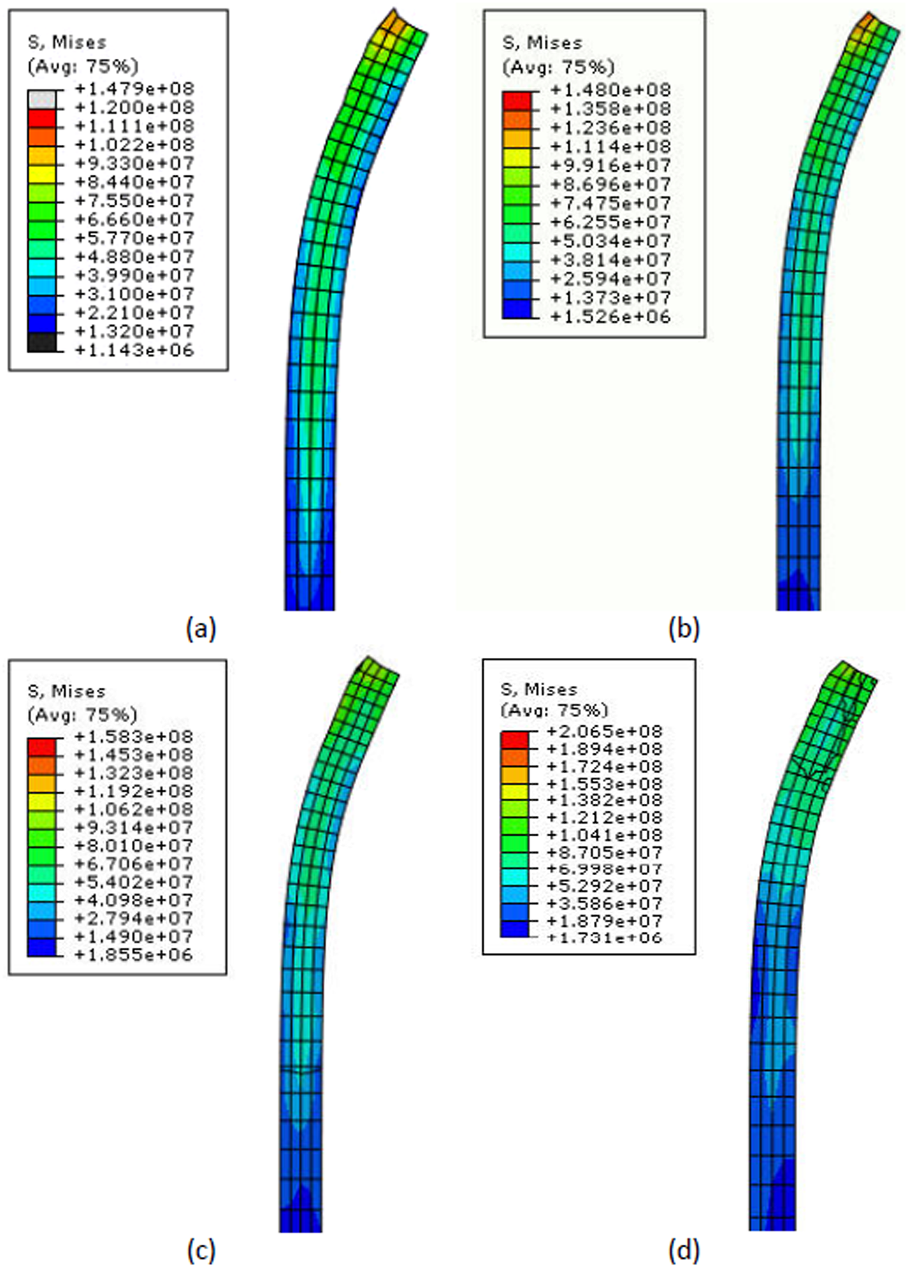
Mises stress distribution for different feed: (a) 1.5 mm/rev; (b) 2.5 mm/rev; (c) 5.0 mm/rev; (d) 7.5 mm/rev.
The deformed shape of the tube, also in Figure 10, shows the reduced amount of shear in higher feeds at the outer layer of the free edge. This can be explained by less material contact at higher feeds, as depicted in Figure 9.
Conclusion
A 3D elastic–plastic FE model of dome forming by hot tube spinning is developed considering the effect of the strain rate on flow stress and validated by experiment.
Bending, elongation, shearing, direct compression under the roller, thickening and thinning modes all arise during a hot spinning process depending on the axial position, RCSP and feed. In the more distant positions from the free end (zone 1), bending is dominant. In the middle portion of the spinning path (zone 2) the direct compression of the roller (in radial direction) has a considerable effect, inducing compressive strain on the outer thickness layer of the tube, while in the middle and inner layers in this zone, elongation in axial direction is dominant. The portion close to the free end (zone 3) is different from the other zones because of considerable reduction of material constraint in the axial flow path. In this area, extensive elongation and shearing is dominant at the outer thickness layer.
It is shown that circumferential strain is independent of RCSP and spinning feed, and is solely affected by the spinning path.
When the RCSP is more distant from the free end of the tube, there is the risk of indentation, local thinning and excessive elongation. It is expected that there is a certain distance of contact start point from the free end; increasing the distance after which causes a dominant change in deformation characteristics.
Axial strain has an inverse relation with the amount of feed in all thickness layers and axial positions (zone 1, 2 and 3), i.e. decreasing the feed results in an increase of the axial strain. The axial strain values at the outer layer are considerably larger than that of the inner layer.
Thickness strains increase with increasing the feed. This means that higher thicknesses are achieved with higher feeds.
The equivalent strain, as a measure of the amount of deformation, increases with decreasing the feed because of the increase in brushed contact area of the roller with the tube.
The amount of residual stress (regardless of the temperature change) slightly increases with increasing of the feed, and its uniformity both along the tube axis and in thickness increases with increasing the distance of the RCSP from the free end.
Footnotes
Acknowledgements
The authors wish to thank Mr Majid Izadi and Mr Abolfazl Moulayinejad from “Middle East Machinery Co.” for providing technical support in experimental studies of the present article.
Funding
This research received no specific grant from any funding agency in the public, commercial, or not-for-profit sectors.