
Abstract
The article presents a dynamic design approach of an ultra-precision machine tool based on the morphology requirements of the workpiece. Compared with common parts, optical parts not only have as many high requirements for surface finish and flatness, but also topographic properties, which leads to a big difference in design with traditional machine tools. This approach, from the topographic properties and functional requirements of the workpiece, demonstrates how to design and analyze the kinematic chain and configuration of the machine tool. Then, a finite element model and mathematical model are established to predict the topographic properties of the workpiece. The design and optimization of an ultra-precision flycutting machine tool is employed as a case study to elaborate the approach in detail. Preliminary machining trials have been carried out and provided evidence of the approach being helpful to design and optimize the ultra- precision machine tool used for optical parts machining.
Introduction
Precision machine tools are essential in the manufacturing field since they directly affect machining accuracy, repeatability, productivity, and efficiency. 1 There are a number of publications on the design approach of precision machine tools. Huo et al. 2 proposed a comprehensive integrated dynamics-driven design and modeling approach, and developed an ultra-precision micro-milling machine tool. Lee et al. 3 used a virtual machining and inspection system to optimize the process parameters and evaluate the quality of the machined surface in ultra-precision diamond turning. Comley et al. 4 and Shore et al. 5 used a new design philosophy that emphasizes the need for dynamic control of the grain penetration depth at high loads to prevent excessive crack propagation below the produced surface. They also developed an ultra-precision grinding machine tool named ‘BOX™’. Cheung and Lee put forward a dynamic surface topography model to predict the surface roughness and three-dimensional (3D) topography of the machined crystalline materials or aluminum alloy.6,7 They analyzed in detail the factors that affected the surface generation, such as tool nose radius, spindle speed, feed rate, depth of cut, as well as the vibration induced by the cutting force fluctuations and the spindle motion errors. They also pointed out that the topographic properties of the workpiece were mainly determined by the machine tool performance and process parameters. However, little attention has been paid to the design of precision machine tools from a dynamics point of view. This means that machine tool developers not only concentrate on the optimization of the machine tool itself in terms of the maximum speed and precision of the machine axes, but also take full account of the dynamics of the machine tool. In other words, the machine tool developers now have to take responsibility for the topographic properties of the workpiece. Therefore, when designing precision machines, it is essential to consider the interaction between the topographic properties, function requirements of the workpiece, and the dynamic performance of the machine tool at an early stage.
In this article, a dynamic design approach based on the function requirements of the workpiece is proposed and employed for design and optimization of an ultra-precision flycutting machine tool. The proposed approach permits analysis and optimization of the overall machine tool dynamics and machining performance prior to prototyping. Based on the proposed design approach, the influence of dynamic performance of machine tool on the 3D topography of the workpiece is analyzed. Preliminary machining trials have been carried out and provide the evidence of this approach being able to assure that the machine functions properly at the first set-up.
A design approach based on the functional requirements of the workpiece
The schematic of the design approach based on the functional requirements of the workpiece is shown in Figure 1. The design process generally starts with the functional requirements analysis of the workpiece. To achieve the requirements, the machine tool behaviors have to be well understood at the conceptual design stage, which contains the design of kinematic chain, configuration, and components. Then, the machine tool developers have to take responsibility for the overall machine’s performance characteristics. This means that, when designing precision machines, it is essential to consider the interaction among the mechanical structure, control system, and electrical equipment at an early stage. It is believed that the machine tool behaviors and their influence on machining performance are deterministic and can be modeled and predicted.8,9 Therefore, a simulation model containing a finite element model and mathematical model are established accurately after the conceptual design. The influence of the interference, such as the cutting force, spindle runout, and external vibration, should be considered to forecast the performances of the machine tool and predict the topography of the workpiece. Then the topography predicted is compared with the requirements, if the predicted topography satisfies the requirement, the prototype can be manufactured according to the simulation parameters used in the simulation model, such as the material, size, and shape of every component, the stiffness of the bearing, and the nose radius of the cutting tool. But if not, the simulation parameters should be revised to rejudge until the prediction topography does satisfy the requirement. The design and optimization of an ultra-precision flycutting machining tool is employed to describe the approach in detail.
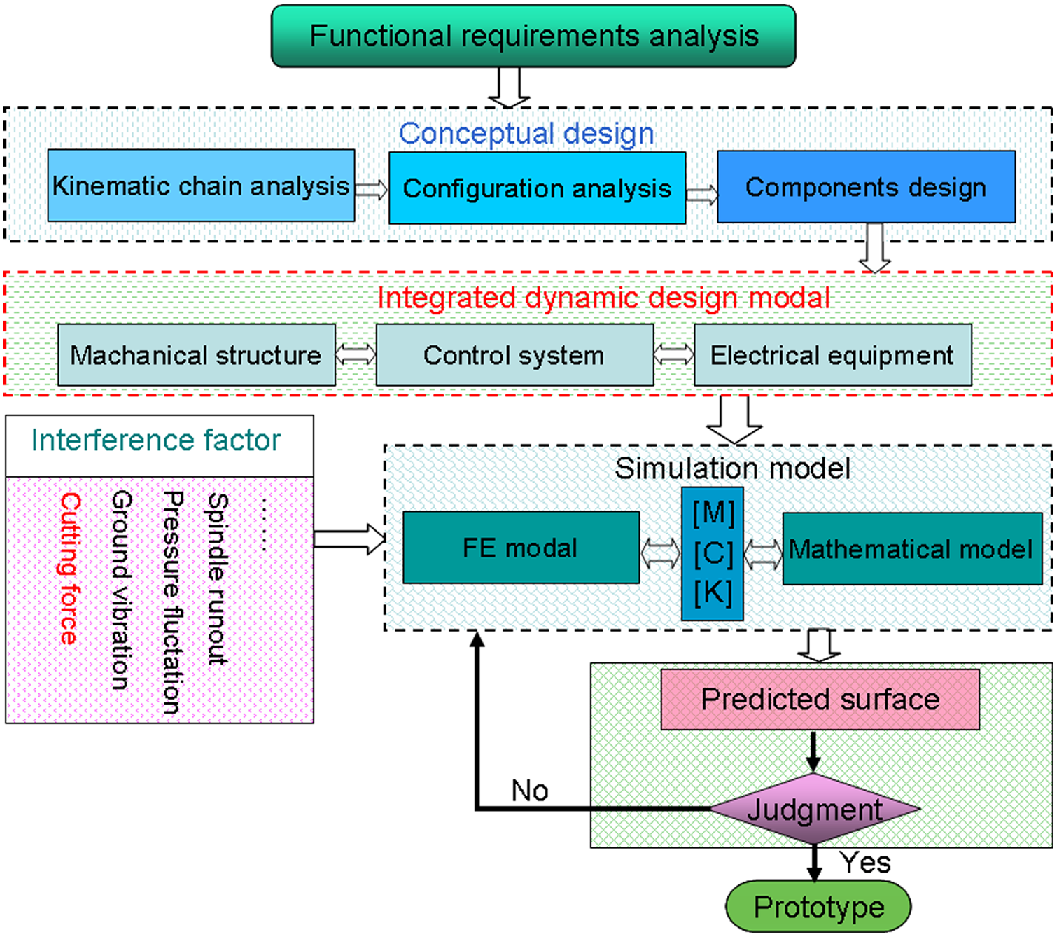
The schematic of the design approach based on the functional requirements of the workpiece.
Design and optimization of an ultra-precision flycutting machine tool
Analysis of workpiece material and functional requirements
The material of the workpiece is potassium dihydrogen phosphate (KDP) crystals, which have good nonlinear optical and electro-optical properties. It mainly functions as harmonic frequency converters in modern high-energy solid state lasers, polarization rotators in Pockels cells, and laser fusion systems in the inertial confinement fusion (ICF) program.10,11 The laser damage threshold of the KDP crystal is an important optical property for the ICF program. Chen et al.
12
pointed out that the laser damage threshold of the KDP crystal is not only affected by the material qualities of KDP crystal, but also the topographic properties of the machining surface. Consequently, the KDP crystal has extremely harsh requirements of the topography. In the spatial frequency region from 3.0 × 10⁻² to 8.3 mm−1 we define a maximum “waviness” in terms of a power spectral density (PSD). The PSD simply represents the square of the phase noise amplitude (nm2) over a certain spatial frequency (mm−1) and thus has the unusual set of units nm2/mm−1 or
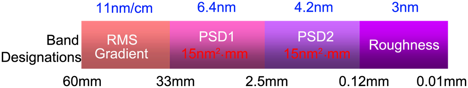
The topography requirements of the workpiece.
If the quality of the machined surface can not satisfy the requirements, the laser damage threshold of the KDP components will descend sharply. 15 Therefore, the factors of surface topography influenced by the machine tool performance must be considered in the design stage of the machine tool.
Kinematic chain analysis
KDP crystal is extremely soft, fragile, gyroscopic, and thermally sensitive, meaning that the traditional grinding and polishing methods are not suitable for processing this kind of material. Single point diamond turning (SPDT) is widely used to machining KDP crystal. Moreover, KDP crystal is a crystal with a negative single-crystal axis and belongs to the tetragonal system, which has a strong anisotropy. 14 The coupling effect of vibration owing to the machine tool and cutting force will lower the surface quality of the workpiece that will be difficult to eliminate. In order to improve the KDP crystal machining process, flycutting technology was used to machine KDP crystal, 16 by which the influence of material anisotropy on surface quality is reduced for its single cutting direction. Therefore, the flycutting format is used in this design.
The simplified kinematic chain of the machine tool is proposed in Figure 3. The diamond cutting tools are installed in a large flycutting head that is driven by the spindle motor. In addition, the feed of the workpiece is achieved by a horizontal-axis slide. With only two axes, this kinematic chain has a short structure loop, which contributes to improve the machining accuracy.
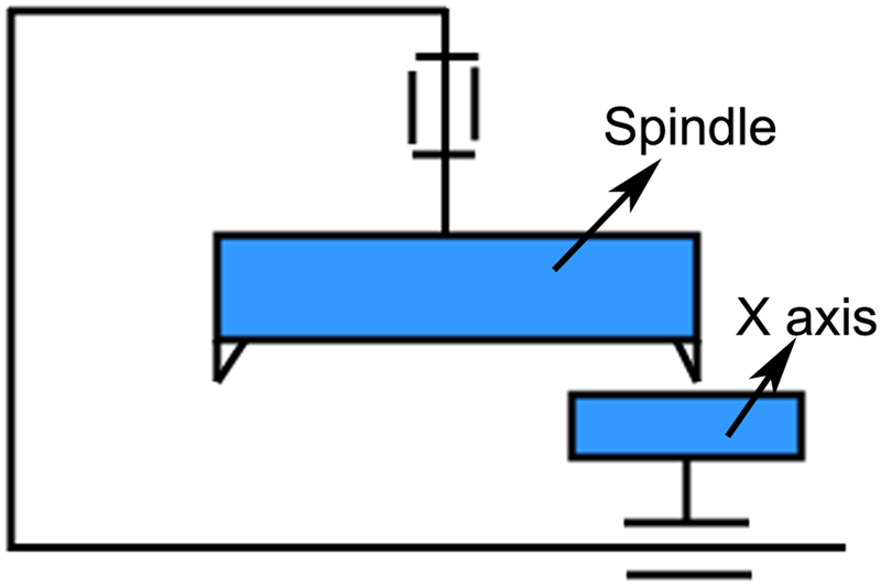
The kinematic chain of the machine tool.
Configuration design
According to the kinematic chain proposed above, the configuration of the flycutting machine tool is given in Figure 4. A bridge supports a vertical-axis spindle and flycutter over a horizontal-axis slide. Mounted to the horizontal slide is a vacuum chuck that fixes the workpiece by vacuum power. The surface to be machined lays in a horizontal plane. The aerostatic bearings are used in the vertical-axis spindle. A large support surface is adopted to improve the stiffness in the axial. The hydrostatic bearings are also employed in the horizontal-axis slide to improve the stiffness.
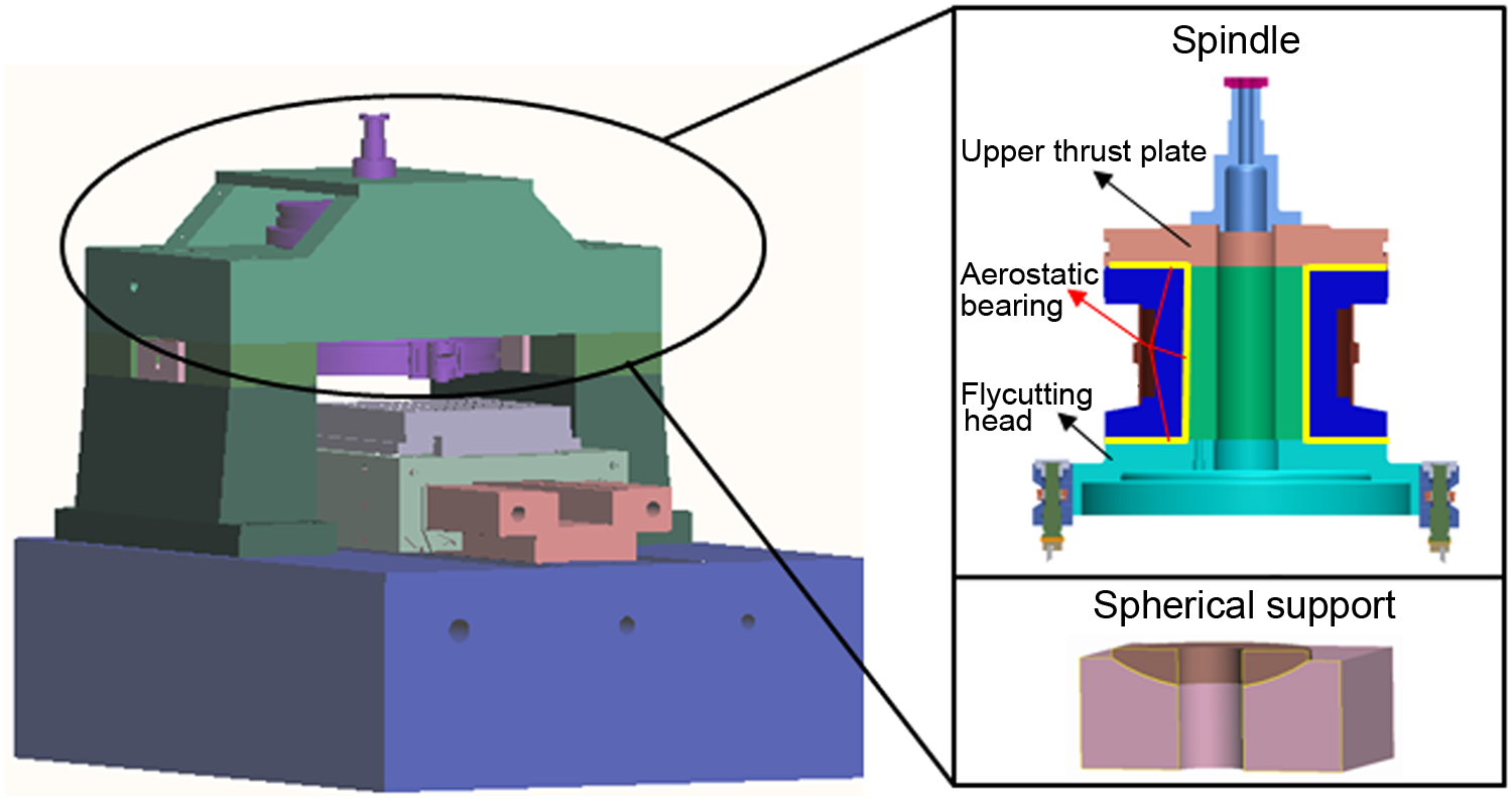
The configuration of the flycutting machine tool.
The structure of the machine tool consists of machine tool bed, column, adjustment pads, spherical pads, and beam. As is shown in Figure 4, the machine structure is symmetrical. Heat from the spindle bearing and motor create a symmetrical temperature profile in the bridge when the spindle is centered, reducing squareness errors caused by thermal distortion of the bridge. Centering the spindle in the bridge also provides a stiffer structural loop between the tool and workpiece, and a lower rotational inertia about the long axis of the bridge. It is suitable for machining larger workpieces. Therefore, a gantry type is adopted in this design.
Modeling and analysis of the machine tool
The joint characteristics of the machine tool, such as the bolt joint and the bearing connection, have great impact on the dynamic performance.17,18 Therefore, the modeling approach of the junction directly determines the accuracy of the whole model of the machine tool. The modeling method of the junction in this article is used as follows: a spring element group generated by codes is introduced to represent the aerostatic and hydrostatic bearing, and the axial stiffness of the linear motors, instead of the four or six elements in traditional modeling methods, to improve the accuracy of simulation. Conta173 and targe170 elements are applied to the contact pairs of the adjustment pad and spherical pad, respectively. At the same time, the Prets179 element is used to simulate the bolt joint, which can exert the preload by node K. The finite element analysis (FEA) model of the whole machine is shown in Figure 5. The 3D-integrated modeling aims to accurately evaluate and optimize the dynamic performance of the overall machine.
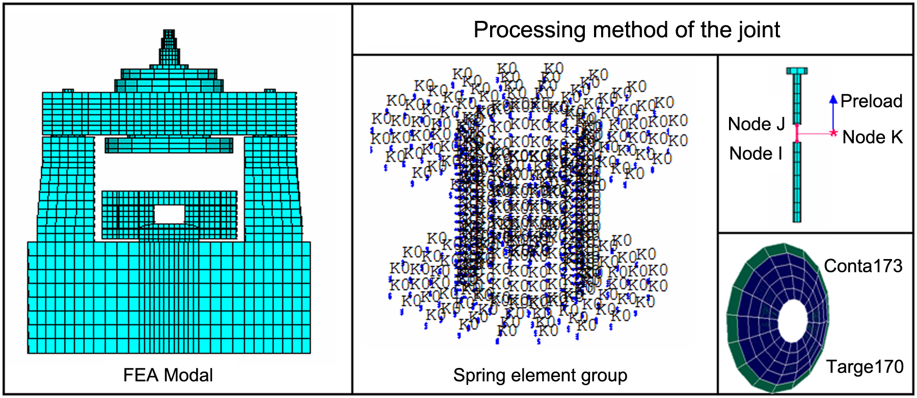
FEM models of mechanical structure.
After establishing the FE model of the whole machine tool, harmonic response analysis is performed to quantitatively determine its steady-state response to loads that vary harmonically with time. The harmonic response analysis is able to verify whether or not the designs will successfully overcome resonance and harmful effects of forced vibrations. A cutting force
Figure 6 provides the harmonic response of relative displacement between cutting tool and workpiece in a sensitive direction (Z direction). The dynamics of the machine tool in this direction is dominated by a structure resonance of 255 Hz. The relevant modal parameters are determined by the frequency response function, which corresponds to a dynamic loop stiffness of 35.7 N/μm, the static stiffness is 500 MN/m and damping factor is 3%.
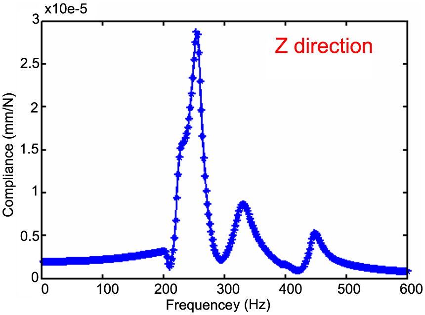
Harmonic response of the machine tool.
Modeling of the cutting force
Many interference factors are involved in the machining process, among which cutting force is the most significant and unavoidable one, so this article focuses on its influence.
In precision flycutting, the tool radius R is larger than the feed

Figure 7 shows a sample workpiece and the key geometrical parameters used to predict the cutting force. The cutting force
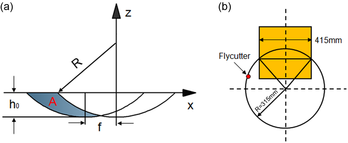
Calculation of cutting force. (a) Chip area formulation for two passes of the tool. (b) Sketch map of cutting loci on surfaces.
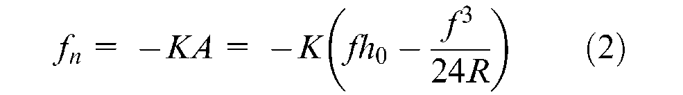
where K is the specific cutting energy and A is the instantaneous chip area removed.
Flycutting is a typical intermittent machining. Figure 7 shows a sample cutting force over two revolutions of the flycutter. In this particular example, the size of the workpiece is 415 × 415 mm2, and cutting occurs during 48.8° to 131.2°.
Performance prediction and optimization of the machine tool
A MATLAB/Simulink model is shown in Figure 8. The cutting force obtained from equation (2) is generated by the pulse generator as the input signal, the transfer function that is obtained from the dominant resonant frequency in a sensitive direction by polynomial fitting, and a fourth-order Runge–Kutta algorithm is used in this Simulink model. The response of the cutting tool is shown in the scope in the Simulink model, which can be mapped to the shape of the workpiece, as shown in Figure 9. 20
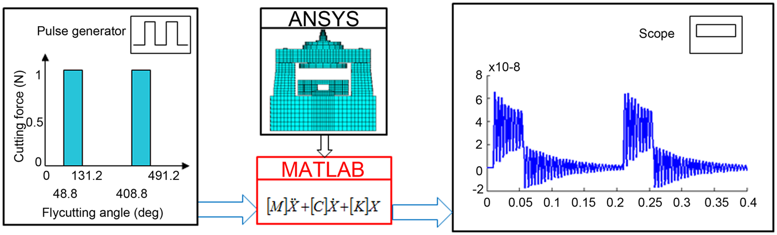
Representative cutting force and tool vibration over two revolutions.
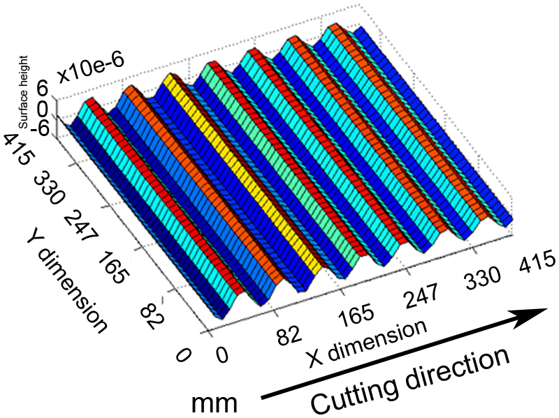
The 3D simulating surface of the workpiece.
From the simulation result, the maximum amplitude and period of the vertical stripes, generated by the tool vibration with the change in stiffness of the dominant mode, are given in Figure 6. In order to satisfy the PSD1, the maximum amplitude of the vertical stripes should be less than 15 nm, and the period greater than 33 mm. Figure 10 shows that the stiffness of the machine tool should be larger than 125 N/μm in order to meet the accuracy requirement of the figure, and the period of the vertical stripes should be less than 800 N/μm in order to avoid affecting the PSD1. Considering the two indicators above, the appropriate range of stiffness for the dominant resonant frequency is 125 N/μm to 800 N/μm, as given in Figure 10, and 500 N/μm in this design.
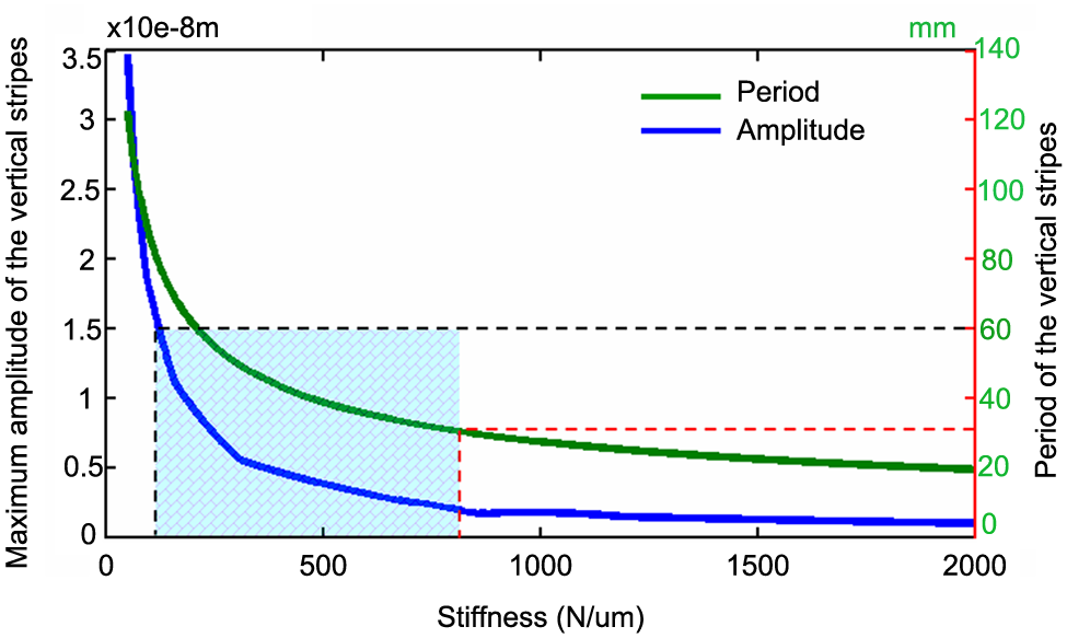
Prediction of the appropriate range of the stiffness.
Preliminary machining test
The ultra-precision flycutting machine tool is optimized according the parameters optimized by the simulation model, as shown in Figure 11. Furthermore, the machining test is carried out on this machine. The machining parameters, such as spindle speed and feed and tool-nose radius, are consistent with the simulation parameters. The experimental results are examined by a 3D rough surface tester, Wyko RST-plus (Veeco Metrology Group, Santa Barbara, CA, USA), which has a 500 mm vertical measurement range and 3 nm vertical resolution. The measurement result with only tip, tilt, and piston removed, are shown in Figure 12. The test results are in good agreement with the analytical and simulation results.
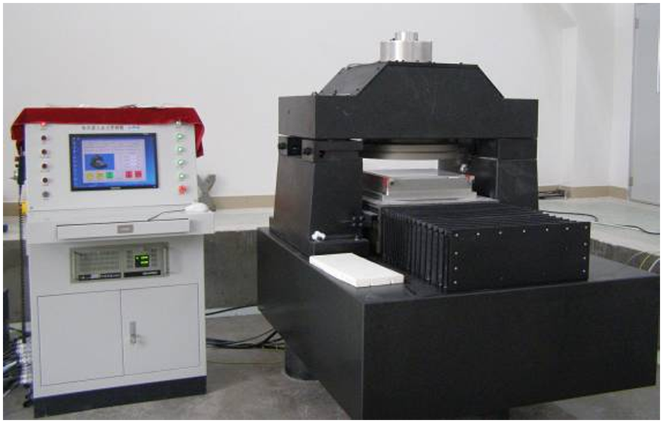
Ultra-precision flycutting machine tool.
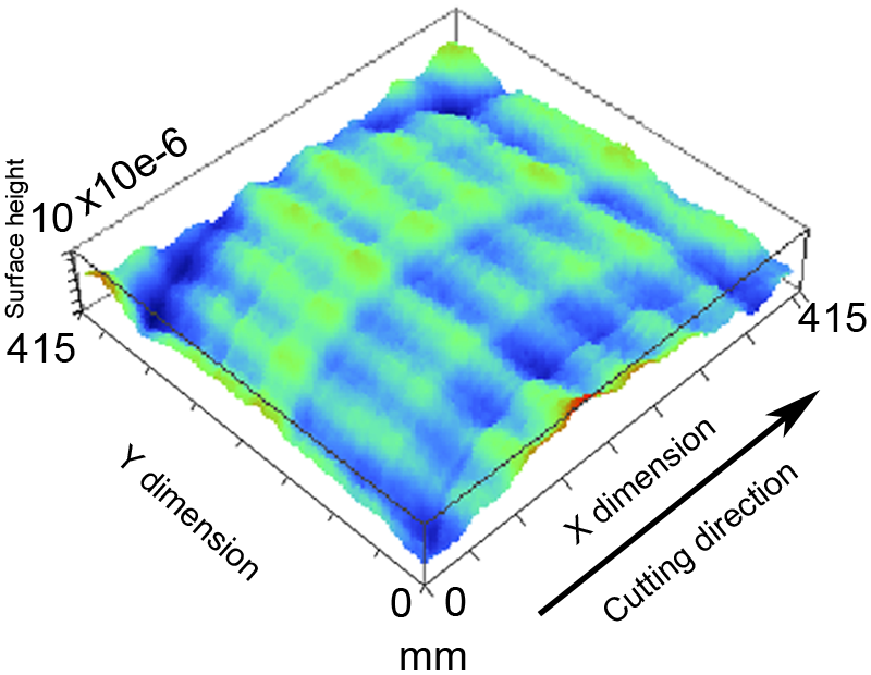
The 3D measuring surface of the workpiece.
Conclusion and discussion
A design approach based on the functional requirements of the workpiece has been proposed and successfully employed to optimize an ultra-precision flycutting machining tool.
A dynamic model considering the influence of joint characteristics is built. A spring element group is generated by codes that can improve the accuracy of simulation.
FEM and Simulink are combined to predict the topography of the workpiece at the design stage.
In the case study, an appropriate range of the stiffness (125–800 N/μm) for dominant resonant frequency is given, which can avoid the adverse effect by excessively high stiffness of the machine tool.
The simulations based on the approach can be used as a powerful tool for supporting the whole design process in an iterative manner, which also enables the machine design to be optimized effectively.
The work in this article will allow the interaction between the topographic properties and function requirements of the workpiece to be better understood. It could be applied to design and optimize the machine tool used for optical parts machining.
Footnotes
Funding
This work is supported by National Science Fund for Distinguished Young Scholars of China [grant number 50925521].