
Abstract
Due to the demand for reduced weight, improved safety, and crashworthiness in vehicles, the need to manufacture automobile structural components from ultrahigh-strength steels is apparent. Indirect hot press forming process is a process developed from hot press forming because of steel’s high resistance to trimming after hot press forming. From the researches about indirect hot press forming, considerable springback in the indirect hot press forming is accrued after preforming. After this trimming, the material is calibrated by hot press forming process. In this article, the springback is accrued at preforming and the final shape of u-bending with varying cooling rates is predicted using ABAQUS software. To find the characteristics and effects of temperature changes during the hot press forming process, high-temperature tensile test with simultaneous cooling is conducted and the results are applied to the analysis. The shape deviations after the indirect hot press forming process are compared according to cooling rate conditions.
Keywords
Introduction
Owing to the limited fossil fuel reserves and environmental problems, research has been conducted on the technologies that contribute to the improvement of fuel efficiency by reducing the weight of automobile parts and to the high stability achieved by enhancing a vehicle’s mechanical properties.
Using the high-strength steel plate formed by the general press method at the car’s body can raise problems in formability of the press process and springback due to the reduction of its elongation in reverse proportion to its strength. 1 Hot press forming (HPF) not only solves these problems but also satisfies the requirements of lightweight and high strength. One of the main advantages of HPF is producing high-strength part by quenching immediately after forming in the die with the steel heated over the transformation temperature, Ac3. Its hardenability and strength are reinforced by adding elements such as B, Mo, and Cr.
There are many researches about HPF. There are advantages such as a decrease in forming load because of the use of heated blanks in forming. These advantages have prompted a great deal of study into the formability of boron steel sheet.2,3 In the basic research of HPF process, Liu et al. 4 investigated various martensitic phases through HPF. Turetta 5 measured the grain size of austenite according to heating time and suggested suitable heating time and temperature. He also measured the hardness of materials with respect to quenching speed. Merklein and Lechler 6 investigated the correlation between heating time and heating temperature of austenite according to sheet thickness. They also investigated the thermal–mechanical characteristics of the sample formed by hot stamping process. 7 Bariani et al. 8 tested the limitation of hot forming in the deep drawing method for the high-strength steel.
Bardelcik et al. 9 studied the effect of quenching speed and strain rate with 22MnB5 steel sheets with four kinds of quenching conditions and researched how strain rate affected the hardness of material through simple tensile tests with these sheets. Jang et al. 10 experimented with a high-temperature tensile test with fixed temperature according to strain rates. Meanwhile, Mori et al. 11 and Kolleck et al. 12 studied about heating method.
On a research about applying the HPF process, Nam et al. 13 and Choi et al. 14 investigated the blank shape of the center pillar and forming process. Moreover, HPF process is applied to vehicle parts such as A-pillar, B-pillar, bumper, roof rail, rocker rail, and tunnel. 15
Ryan et al. 16 studied the hot forming die by which various mechanical properties could be partially obtained through the control of the cooling rate in hot forming. Xing et al. 17 verified the springback that depended on blank holder force, clearance, and die radius, using an experimental technique after the theoretical analysis was performed by a simulation through ABAQUS.
There are many researches about springback. Carden et al. 18 suggested a standard on the measurement of springback. Ling et al. 19 predicted the springback after the L-bending process by finite element method (FEM). Cho et al. 20 and Leu 21 predicted the springback in u-bending analysis.
However, one problem existing in the HPF process is trimming. Because boron steel sheet changed to hard material during martensitic phase, much cost and time were needed in the trimming process. To address these points, Choi et al. 22 studied partial heating and trimming techniques. On the other hand, indirect hot press forming (IHPF) was recently introduced and investigated. 23
IHPF is the process of adding cold forming process before HPF. IHPF has an advantage of easy trimming and calibration after cold forming. After trimming, the material was heated and formed (second forming) simultaneously with quenching for strong property similar to HPF. However, there is little research about the prediction of springback for vehicle parts applied to the IHPF process with tensile test simultaneously with cooling results.
For the basic analysis in this article, the springback occurred at cold forming, and the second forming in IHPF was predicted. Finally, the final shape through IHPF was also predicted by ABAQUS. The experiments and analysis were conducted based on u-bending test. The existing material used for HPF simulation was the result of high tensile test with fixed temperature. It was applied to the analysis of the corresponding temperature. Errors occurred because the results of tensile tests with fixed temperature were different with the real HPF process. To overcome this problem, high-temperature tensile test was conducted simultaneously with cooling for copying the HPF process and it was applied to the analysis. The experiment was conducted with four cooling methods and three strain rates. The final shape after releasing restriction of dies was predicted according to the cooling rate.
Experimental conditions and equipment
Experimental conditions and equipment of high-temperature tensile test
Existing material properties present in the tensile test results with fixed temperatures were assumed to produce errors at the forming analysis in the HPF process. Those material properties with fixed temperatures were different from the actual HPF process. In the HPF process, forming was completed within 5 s, and after this, the strength increased during the holding time. The sheet was formed and simultaneously cooled during forming process. For this reason, tensile test simultaneously with cooling was conducted to copy the HPF process. These results were applied to second forming in the IHPF process.
The equipment for high-temperature tensile test is shown in Figure 1. A 25-ton dynamic material testing machine and 25-kN load cell were used. For heating, a heat chamber that could maintain 1200 °C of atmosphere temperature was used. A 22MnB5 material with a thickness of 1.6 mm was manufactured depending on American Society for Testing and Materials (ASTM) E-8M standards for tensile test. Thermocouple was attached to the specimen to measure the cooling rate. Generally, 22MnB5 sheet was heated above 900 °C for 5 min5,7 and was applied to this experiment. There were four kinds of cooling methods like water cooling (WC), cooled air cooling (CAC), air cooling (AC), and furnace cooling (FC). In addition, there were three kinds of tensile velocity that made strain rates of 0.1, 0.05, and 0.01 s−1. To determine the strain rate, tensile test before experiments was conducted because each velocity according to strain rate was different.
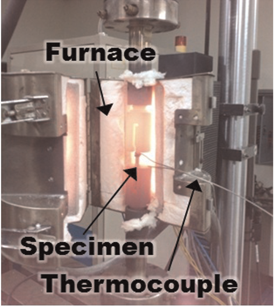
Equipment for tensile test and high-temperature furnace.
Tensile and cooling were conducted 3 s after opening the heat chamber to consider transfer time. WC is the method in which water was sprayed at heated specimen during tensile test with its cooling rate appearing at 90 °C s−1. CAC is the method in which −15 °C of cooled air from vortex tube was sprayed at the specimen with its cooling rate appearing at 40 °C s−1. AC is the method in which room temperature (RT) air was sprayed by air gun with 20 °C s−1 of cooling rate. FC is done with an open chamber with 0.5 °C/s of cooling rate. The graph matched with the continuous cooling deformation diagram of 22MnB5 material 24 is shown in Figure 2.
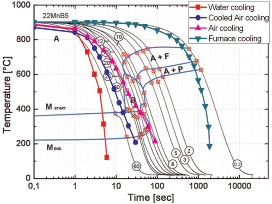
Comparison of cooling rate conditions with continuous cooling transformation (CCT) diagram of boron steel.
Tensile test conditions of 22MnB5 material after quenching
In the HPF process, material properties between second forming and after quenching are far different. To obtain material properties after cooling, tensile test was conducted with the following four cooling methods: water quenching, die quenching, wind cooling, and AC. Water quenching means placing the specimen in water. Die quenching means the specimen is cooled in both the upper and the lower die with a small amount of pressure by hand. The cooling method done with electric fan is named wind cooling, and cooling naturally in the air is named AC. Each of the cooling rates is shown in Figure 3. The cooling rates were measured as 450, 60, 22, and 12 °C s−1, respectively. The tensile test was conducted after cooling the specimen from 900 °C to RT.
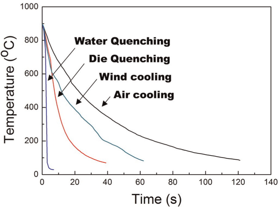
Cooling rate distributions according to cooling method.
u-bending experimental conditions
The object of this article is prediction of final shape of u-bent shape after IHPF process. Before the analysis, u-bending experiments were conducted to verify the validation of later analysis. The springback measured after u-bending experiments will be compared with analysis results of u-bending. U-bending analysis for comparison with experiments was also conducted with same condition of experiments.
The equipment used in the u-bending experiment consisted of 50-ton hydraulic cylinder for moving punch, 30-ton load cell for measurement of forming load, 20-ton hydraulic cylinder for clamping upper die and lower die, and 5-ton load cell for measurement of clamping load. The related experimental equipment is shown in Figure 4. The punch velocity was fixed with 3 mm s−1. The edge of lower die and punch was manufactured as insert type and the radii of insert were 2, 5, and 11 mm. The experiment was conducted with the following three conditions: c/t = 1.0, 1.5 and 2.0, where c is the clearance between punch and lower die and t is the thickness of the material. A 22MnB5 material, which had thicknesses of 0.6 and 1.2 mm, was used in this experiment. The dimension of the specimen was manufactured as 120 mm × 150 mm. L18 (33 × 21) of the arranged table was made by Taguchi method. 26
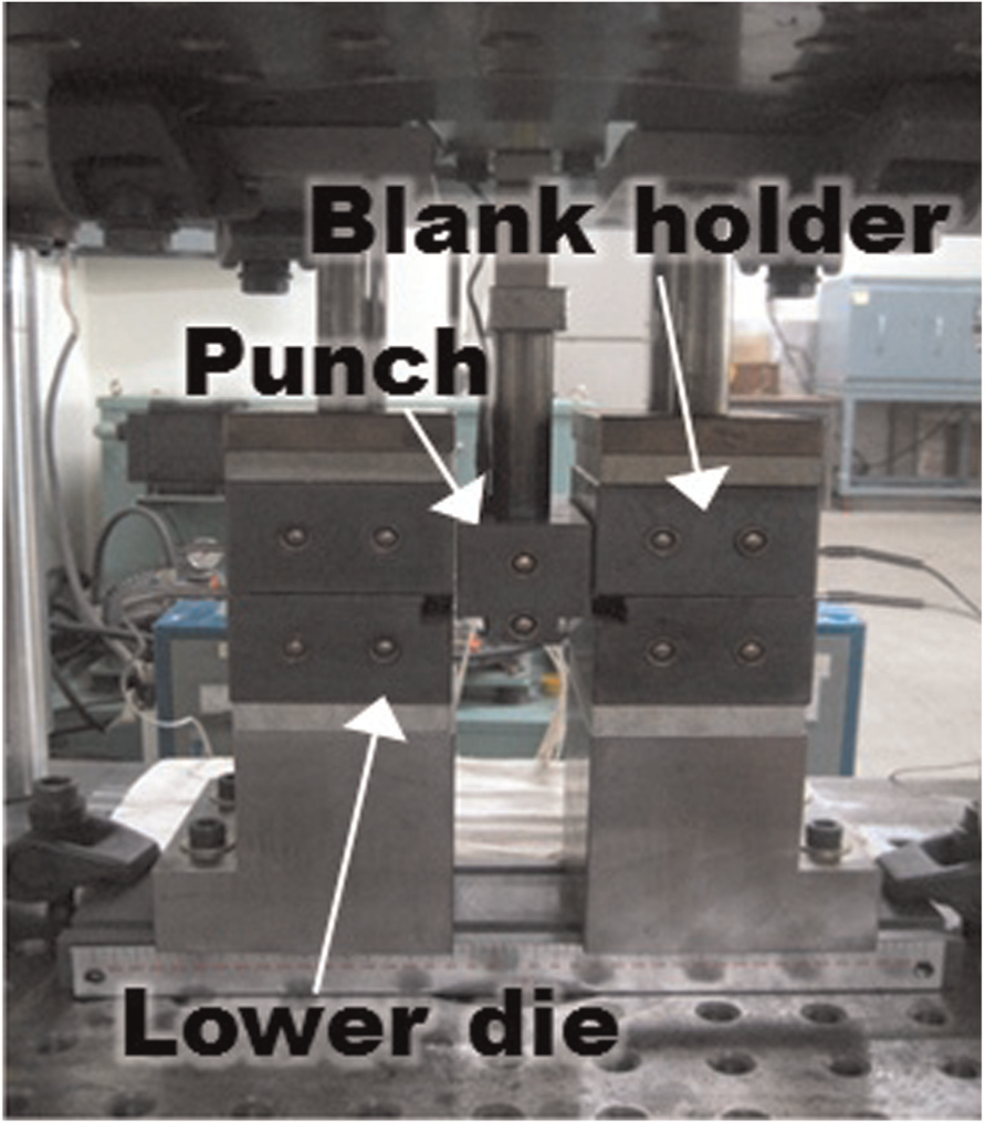
Equipment of u-bending punch and die.
Results and discussions
High-temperature tensile test results
Flow stress according to cooling rate and strain rate
The results of high-temperature tensile test according to strain rate and cooling rate are shown in Figures 5 and 6, respectively. The scale of these figures was different because their stress value gaps were quite large. The tensile test with a high strain rate of 0.1 s−1 showed insignificant difference in tensile strength between WC and CAC conditions and also AC and FC conditions. However, the elongation of each cooling method was different. The elongation increased according to the decrease in the cooling speed. These differences were from the different temperatures during the tensile test. The temperature during the deformation made the significant difference in material properties because of its high tensile speed. When the specimen is cooled by WC condition, the temperature during the tensile test must be lower than other cooling conditions and this is the reason why the WC condition shows the higher tensile strength than other cooling conditions. Phase transformation might be occurred, however, because the transformation occurred at the end of the tensile test, a strong property did not appear. It was considered that during the tensile test, there is insignificant transformation effect when the strain rate was 0.1 s−1.
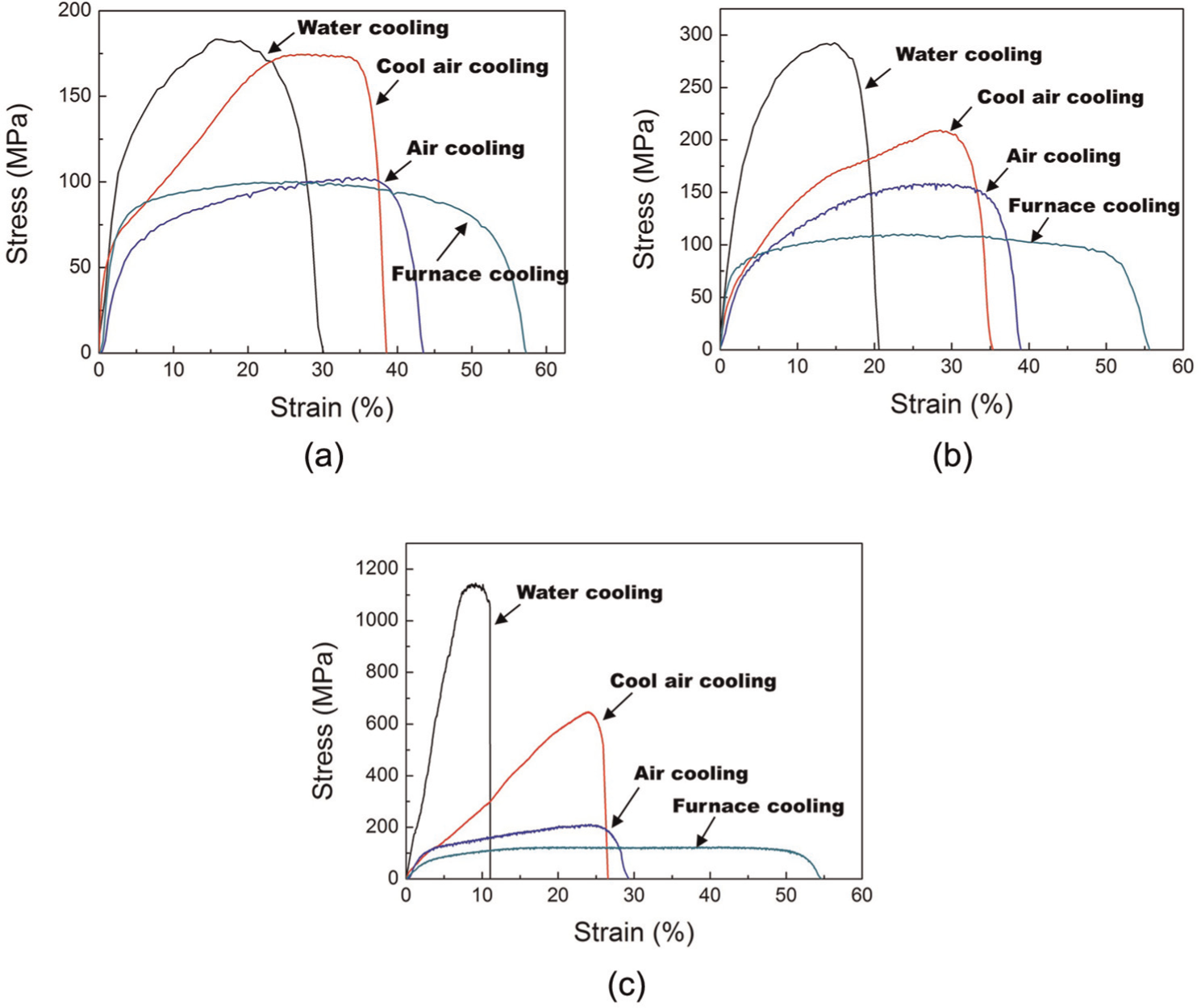
Stress–strain curves from tensile simultaneously with cooling considering four cooling methods and the following strain rates: (a) 0.1 s−1, (b) 0.05 s−1, and (c) 0.01 s−1.
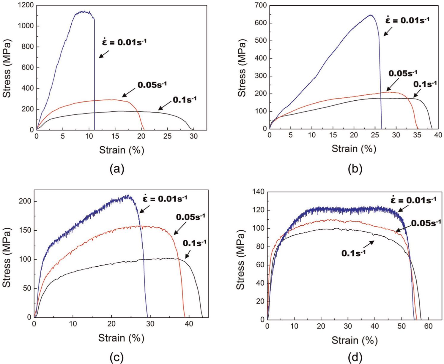
Stress–strain curves from tensile simultaneously with cooling considering three strain rates and the following cooling methods: (a) WC, (b) CAC, (c) AC, and (d) FC.
On the other hand, in case of strain rate of 0.01 s−1, the specimen was rapidly cooled to RT and it caused the phase transformation of 22MnB5 material. From this, it can be seen that the strain decreased and tensile stress increased upon higher cooling rate with considerable strength from the phase transformation. Meanwhile, FC condition was similar to the existing tensile test that was conducted with fixed temperature. Only FC condition was irrelevant with different strain rates. In the second forming analysis, a strain rate of 0.05 s−1 was selected as it was the middle parameter in the series of strain rate values (0.1, 0.05, and 0.01 s−1) during the experiments.
Microstructure and hardness results
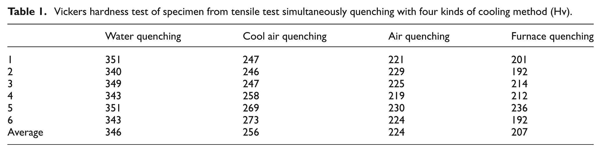
Two specimens were selected from each cooling method after tensile test, while cooling and hardness tests were conducted simultaneously three times for each specimen. The hardness test results were shown in Table 1. The following four cooling rates were used in this experiment: 90, 40, 20, and 0.5 °C s−1. General hardness from these cooling rates was supposed to be 474, 472, and 410 Hv, respectively 9 (except 0.5 °C s−1 condition). However, the hardness test results appeared as 346 Hv from WC condition, 256 Hv from CAC condition, 224 Hv from AC condition, and 207 Hv from FC condition. These differences were caused by tempering. High-temperature tensile test in this article was conducted in the heat chamber, which caused the tempering during extraction of the specimen from jig after the tensile test was completed. Though the hardness test results were different with the expected results, the experimental results were reliable because the temperature of the specimen followed each of the four cooling rates from the tensile start to the fracture of the specimen.
Vickers hardness test of specimen from tensile test simultaneously quenching with four kinds of cooling method (Hv).
The microstructure following high-temperature tensile done simultaneously with cooling was checked to verify its low hardness through a scanning electron microscope. The microstructure is shown in Figure 7.
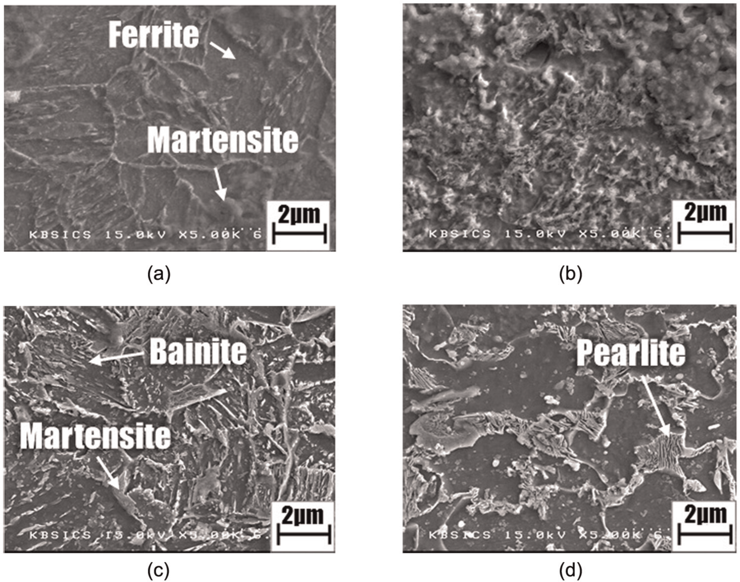
Microstructure of 22MnB5 steel according to cooling rate through a scanning electron microscope: (a) water cooling, (b) cooled air cooling, (c) air cooling, and (d) furnace cooling.
The specimen with WC condition showed the tempered martensite structure with little bainite structure, as shown in Figure 7(a), and the microstructure related to this was researched by Alireza. 25 The specimen cooled with CAC condition showed the complicated structure as shown in Figure 7(b). Even though some various structures are mixed, it is considered that the broken martensite and bainite structures exist. The specimen with AC condition showed the bainite and ferrite structures as the base materials, as shown in Figure 7(c). The pearlite and ferrite structures were the base materials in the furnace-cooled specimen as shown in Figure 7(d). From Figure 7, evidence of tempering was detected, which caused the low hardness after high-temperature tensile was applied simultaneously with cooling experiments.
Tensile test after quenching results
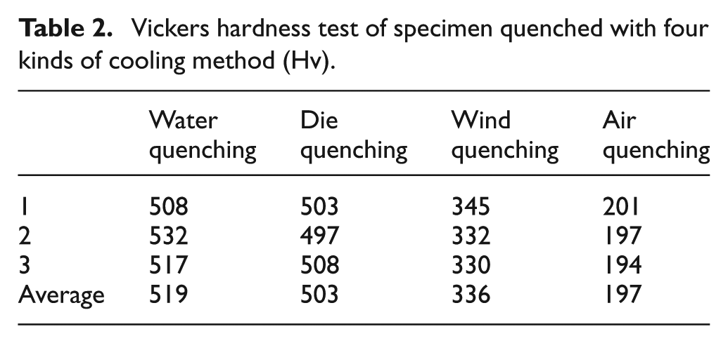
The results of tensile test at RT are shown in Figure 8 according to the four cooling methods, and the hardness test results are shown in Table 2, which are 519, 503, 336, and 197 Hv, respectively.
Before applying the tensile after the cooling result, the maximum flow stress lower than 300 MPa was applied in the second forming. After comparing this low flow stress with tensile after quenching results, it was found that 300 MPa was too low to make a difference in springback even in any kind of tensile after the cooling results were adopted. This meant that the tensile after four different cooling methods did not make the difference and any quenching or cooling method could be adopted. However, in terms of copying the real forming process, die quenching method was adopted semantically.
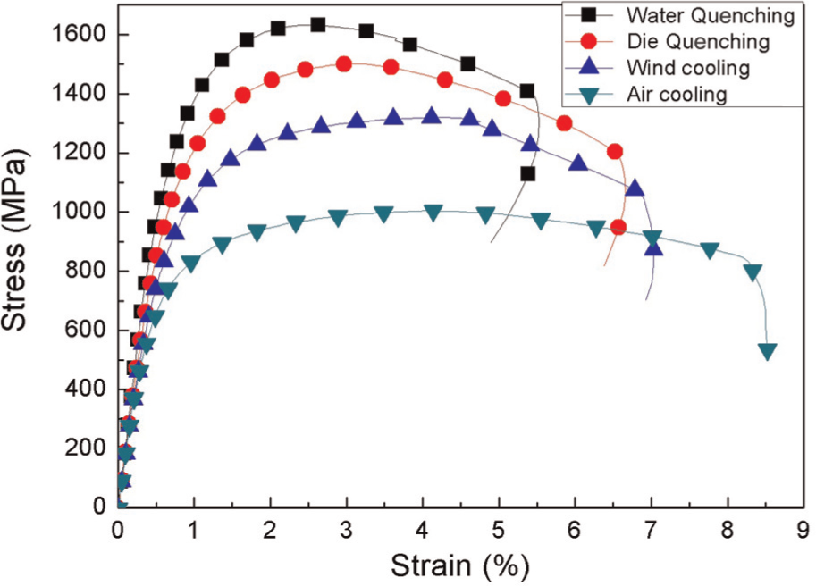
Tensile test results in room temperature according to four kinds of cooling rate conditions.
Vickers hardness test of specimen quenched with four kinds of cooling method (Hv).
Comparison of cold bending results with analysis
The cold bending analysis was conducted by ABAQUS software for verification of analysis for later works. Springback is defined in Figure 9. The equipment and 22MnB5 sheet were designed as real dimension equipments. Two-dimensional (2D) modeling for reducing the analysis time was applied. To describe the curved surface, four elements were used in the direction of thickness, and the analysis was based on the implicit condition. In this analysis, the punch velocity was 3 mm s−1, same with the experiment.
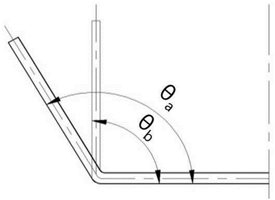
Definition of springback for measurement.
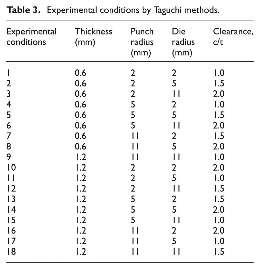
The analysis was also conducted based on Taguchi method as shown in Table 3 to compare with experiments. The comparison of analysis results with experimental results is shown in Figure 10. In condition 8, analyzed springback appeared bigger than the experimental result as 6.4°. While in condition 1, analyzed springback appeared less than the experimental results as 2.8°. Despite this gap, the general tendency of analysis results was considered similar to the experiment. The springback was measured as 17.5° at the target condition 5 in the bending experiment. The experimental condition 5 was chosen for adapting to second forming and final springback analysis because it had the medium level of punch radius, die radius, and clearance. The second forming analysis was conducted after the annealing process. The annealing process should be conducted during the heating process in the HPF process. Finally, an analysis of removing the restriction of dies for final springback generation had been conducted with condition 5.
Experimental conditions by Taguchi methods.
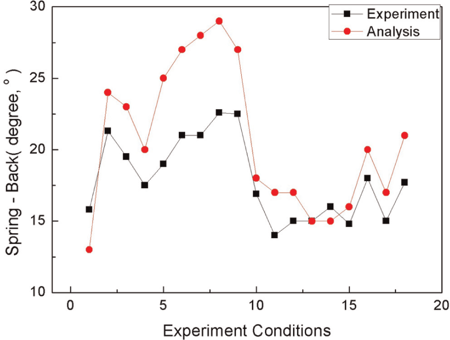
Springback comparison between analysis and experiments.
From the comparison of experiments and analysis, there were some reasons that made some errors. One of which was that the clearance between the upper die and lower die was not easy to control accurately because of its thin sheet and ignored anisotropy.
The certain constitutive material models for forming analysis was not adapt in this analysis. Rather, the stress–strain curves from experiments were adopted for forming analysis as a basic data. Although development of good constitutive model is important, this study aimed mainly to analyze the HPF process without complex material model by using the tensile simultaneously with cooling result in specific HPF case. From this, the influence of the cooling rate on the second forming and the final shape according to the cooling rate were researched.
Prediction of final shape after IHPF process following cooling rate
Analysis conditions for prediction of final shape of u-bending
The microstructure and phase changing related with temperature during the HPF could not be predicted by the analysis. To overcome this problem, experiments were conducted, copying the IHPF process, and the experimental results were applied to the analysis. The material property obtained in section ‘Experimental conditions and equipment of high-temperature tensile test’ of this article was applied to the second forming analysis, where the heated sheet was deformed simultaneously with cooling. When the bent sheet was elastically recovered by removing the restriction of dies, the material property obtained in section ‘Tensile test conditions of 22MnB5 material after quenching’ was applied, and the thickness of boron sheet for analysis is 0.6 mm, same as condition 5.
The heat expansion and heat transfer were ignored in the analysis because they were already considered during the experiments. Moreover, controlling the temperature and cooling rate in the analysis to be same with the experimental result was very difficult. For this reason, the temperature of second forming and sheet releasing process for springback generation was considered as RT with special material data from tensile and applying simultaneously cooling result. It was assumed that the changing of material property during second forming can be considered by adopting the tensile test result with simultaneous cooling.
The annealing process was quite important because residual stress was removed by heating to 900 °C and it could affect the prediction of springback. The most residual stress was removed after cold forming from the annealing analysis conducted by ABAQUS. From this, it can be seen that the effect of residual stress from the cold forming on the second forming process appears insignificant. The bent shape after annealing with little residual stress was an initial state for second forming by using predefined field method.
The shape after annealing was not changed because heat expansion was ignored. It could result in some errors in prediction of springback, but the main objective of this research was the suggestion of a method that can be adopted for analysis of HPF process without the development of complex material model.
The second forming analysis was conducted with four kinds of cooling rates because different cooling rates at the second forming process can cause different residual stresses and elastic recovery forces. Strain rate was fixed as 0.05 s−1, as mentioned before. Tensile test results according to the four cooling methods, WC, CAC, AC, FC (heating and directly cooling without tensile), were applied to the analysis. Because bent sheet was in the restriction of dies, most of the bent shape was similar but there were differences at residual stresses according to the cooling method. In the case of FC and AC, the relatively low yield stress made the plastic deformation at the bottom of U shape. It was considered that the plastic deformation would have an effect on the final shape.
The final analysis is removing the die contact from the bent sheet. By removing the die contact, springback can occur and we can predict the final shape. The second forming results were to be an initial state of this analysis by using predefined field method in ABAQUS. In that analysis, the bent sheet was supposed to be quenched. Based on this, the die quenching result was applied for quenching analysis.
Analysis results of final shape after u-bending
The final shapes after IHPF process are shown in Figure 11. Springback was generated at 9° with WC method, 6° with CAC method, 5° with AC method, and 4° with FC method. From the results, high cooling rate, as in WC method, showed maximum springback at 9°. Because of the high cooling speed, average forming temperature was relatively low and it caused high residual stress during WC method at the tensile experiments using simultaneous cooling. After this work, verification of validation was conducted by u-bending experiments adopting bending with simultaneous cooling.
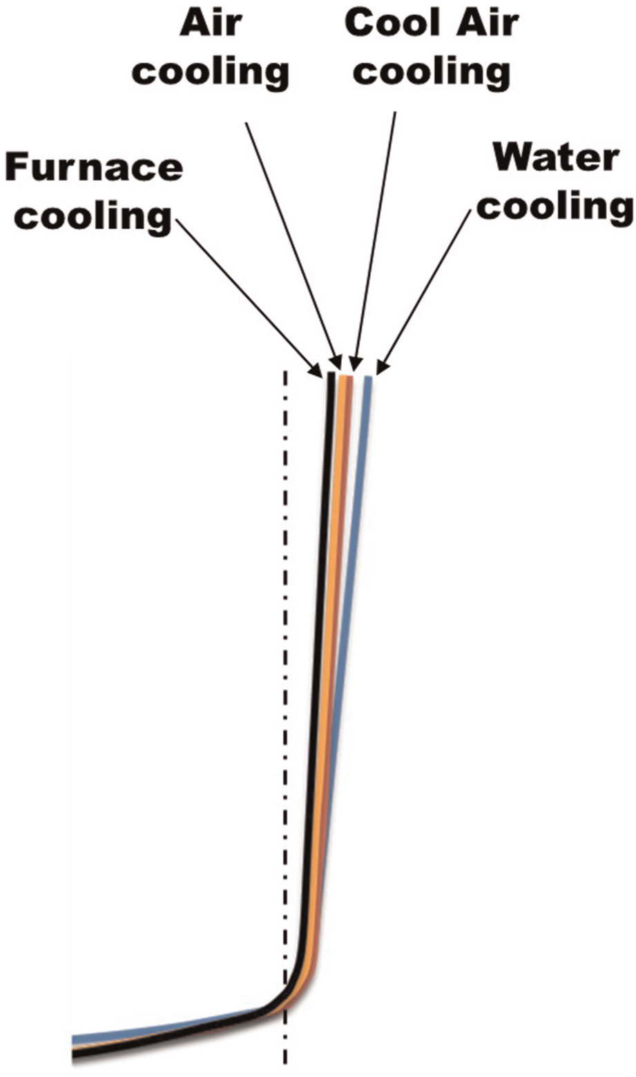
Analysis results of final shape with springback according to cooling rate conditions during tensile tests.
Nonetheless, the IHPF process including cold u-bending process was applied in this research. However, the object is quite different compared with cold u-bending process. Forming analysis of cold u-bending was not for the prediction of springback as it was already studied by many researchers; it was just for the preparedness of other works like second forming and springback analysis after second forming. The shape after cold forming is quite important to predict springback even though its residual stress was removed by austenization process.
Since this shape after cold forming could affect the second forming and even the final formation, the IHPF process was based on the cold forming experiment and analysis. As mentioned before, the u-bending test with heated material with simultaneous bending should be conducted to verify the validation of second forming.
Conclusions
This study used the high-temperature tensile experiment, which was applied to the analysis on the springback, depending on the cooling rate simultaneously with forming based on the investigation of the microstructure and flow stress changes due to cooling rate. Therefore, the high-temperature tensile test with simultaneous cooling experiment was conducted, and the result was applied to the forming analysis in the form of stress–strain curve. The analysis was based on the cold work, which was an adoptable assumption since the heat conduction of material or expansion had already reflected on the stress–strain curve. The special tensile experiment and the analysis by using those experimental results can be concluded as follows:
From the high-temperature tensile simultaneously with cooling results, it is considered that there is no effect of phase transformation in stress–strain curve when the strain rate is faster than 0.1 s−1. However, in case of lower strain rate than 0.1 s−1, the phase transformation effect seems to be applied.
The hardness of specimen after tensile simultaneously with cooling process shows the lower values compared with its expected values because the tempering occurred after tensile and cooling finished. However, the tensile with cooling results is reliable because the tempering occurred after tensile finished.
With the strain rate of 0.1 s−1, there are little differences in tensile strength between WC (90 °C s−1) and CAC (40 °C s−1). However, the residual stress must be different because the stress value is quite different from any specific strain value. This difference gap following cooling rate is increased when the strain rate is decreased.
The final shape of u-bent material through IHPF was predicted as 4°, 5°, 6°, and 9° according to FC, AC, CAC, and WC, respectively. It was expected that this result was affected by temperature during second forming as in the investigation above. With the high cooling rate during second forming, the material was formed at relatively low temperature and a great deal of springback resulted from its high flow stress.
Footnotes
Funding
This work was supported by the Korea Research Foundation (KRF) and Korea Institute of Energy Technology Evaluation and Planning (KETEP) and grant funded by the Korea Government MEST (No. 2012-0001204) and Ministry of Knowledge Economy (No. 20104010100540).