
Abstract
The present investigation describes a computational fluid dynamics approach to study the effects of friction stir welding tool profiles on the thermal conditions and material flow in welds. The aim is to observe the temperatures of the weld and material flow with respect to different probe profiles. For the modeling purpose, temperature dependent material properties and stick–slip conditions between the tool and work material were incorporated. The results from the model exhibited most of the process characteristics of friction stir welding, such as the difference in temperatures of advancing and retreating sides of the weld, temperature contours ahead and behind the tools along the weld, and flow fields. The thermal condition exhibited temperatures that were close to experimental values and below the melting point of the aluminum alloy.
Introduction
Friction stir welding (FSW) is a relatively new solid-state joining process involving no melting of base metal. The relative motion of one material against another causes frictional heating and plasticizing (softening) of the material, and the final joining occurs owing to pressure forging of the material together. During FSW the solid-state joining occurs below the solidus temperature of the equilibrium of phase diagram for the material being joined. As the joining of the material occurs below the melting point temperature, the weld experiences a fine grained microstructure with high strength and ductility. FSW uses a spinning tool to heat the joint material by friction and plastic deformation within 70%–90% of solidus temperature. The spinning pin tool extrudes material from one side to the other in distinct flow patterns, where it is forged together and consolidated behind the pin. This is a licensed process of The Welding Institute (TWI), Cambridge, UK. 1 The typical process and some standard nomenclatures of FSW are illustrated in Figure 1(a).
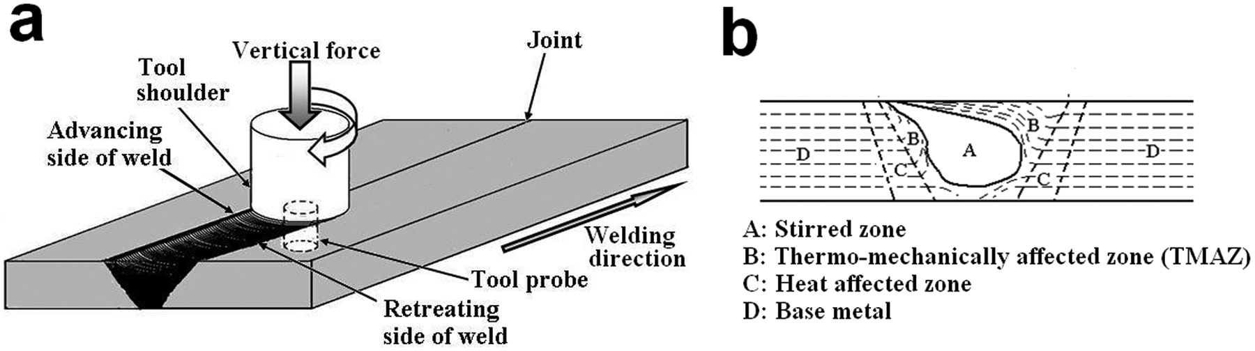
Schematic of: (a) FSW; (b) weld cross-section zones.
FSW can even join dissimilar and thermallyun-weldable material. The pressure and friction from the rotating FSW tool induces intense local shear deformation and heating in the material surface resulting in refinement of its microstructures. As the heat is inherently generated in the process itself owing to friction of the tool–work piece interface and plastic deformation of the material, hence the FSW mechanism is fully coupled. Therefore, tool shoulder geometry and probe profile play a significant role in the final thermal condition of the weld and stirring/mixing pattern of the joint material. The material flow pattern is strongly dependent on the properties of material, welding process parameters and tool geometries. Therefore, to achieve a sound weld, the welding variable plays a significant role. The temperature, strain rate and frictional condition interface of the tool and work piece strongly influence the viscosity of the FSW weld.
The transverse section of a FSW joint consists of a dynamic re-crystallized zone (nugget), thermo-mechanically affected zone (TMAZ), heat affected zone (HAZ) and base metal, as depicted in Figure 1(b). Depending on the operational parameters, the tool geometries, temperature and work piece material, various nugget zone shapes are formed. TMAZ encompasses plastically deformed material. The HAZ indicates the portion of base material that is heated sufficiently, but not mechanically deformed.
Considering the complexities involved, it can be stated that the FSW process is fully coupled with respect to material flow and frictional contact condition of the system. The problem is thermo-mechanical in nature and a thermal model alone might not be adequate for the modeling. The viscosity of the AA 6061–T6 alloy, as a function of shear stress and temperature, had been experimentally determined and used in a three-dimensional (3D) coupled thermal model for predicting the temperature profile of FSW by Smith et al. 2 A two-dimensional (2D) finite element (FE) model, using ABAQUS software and a 2D computational fluid dynamics (CFD) model using FLUENT software was introduced by Reynolds et al. 3 for modeling the FSW process to reveal the material flow around the pin. Shercliff and Colegrove 4 concluded that the heat generation, with constant friction stress at the shoulder and work piece of FSW, is equal to the yield stress of the work material. They further investigated from the CFD modeling FSW that the temperature profiles and weld qualities were affected by the tool material. 5 Khandakar et al. 6 used the power consumption of the machine (torque at tool) in the calculation of heat dissipation during FSW. Song and Kovacevic 7 suggested that the temperature in the vicinity of the FSW tool surface could be very close to the work piece melting temperature. Schmidt and Hattel 8 modeled a FSW heat source by using Columb friction with a coefficient. A CFD model was presented by Colegrove and Shercliff 9 to analyze the heat transfer and material flow during FSW. In this model it was reported that, for a threaded tool, an excessive amount of heat was generated leading to large over prediction in the weld temperature. 9 An experimentally determined FSW machine power, used by Khandakar et al. as a distributed heat source in numerical modeling using a quasi-frictional model, confirmed that heat generation was proportional to the velocity of the tool–work interface. 10 A mathematical model by Nandan et al. 11 was developed for predicting viscous flow, temperature flow and temperature field of friction stir welded austenitic stainless steel. The equation of conservation of mass, momentum and energy in 3D, using spatially variable thermo-physical properties, was solved. 11 Schmidt and Hattel 12 introduced the thermo pseudo mechanical model (TPM) model, which explained the gap between the pure thermal and thermo-mechanical model. The material flow and frictional heating in FSW, with respect to two mechanical boundary conditions like sticking constant velocity and slipping variable shear stress, were investigated by Liechty and Webb. 13 Comparison with experimental data suggested that the variable shear model is superior to a sticking condition and material simply extrudes around the tool, while the constant velocity model predicts a region of material that rotates with the tool. 13 Atharifar et al. 14 considered the stick–slip condition with temperature depended material properties for CFD modeling, for simulating the material flow and heat transfer of FSW of 6061c–T6 aluminum alloy, with an assumption that the viscous and frictional heating were the only source of heat input. The present investigation deals with the analysis of material flow and heat transfer of series 1100 aluminum alloy, with respect to different tool geometries. The effect of the shoulder and pin probe profile on material flow and thermal condition were investigated. The partial slip–stick condition of heat generation was used in the model. The effects of tool geometries in the stirred-zone material flow around the tool probe visualized in the model. In the course of model verification good agreement was observed between the experimental and numerically predicted thermal results.
Experimental details
A vertical milling machine, having 7.5 hp main power drive capacity, was used to carry out the experiment. 15 The FSW tools, having straight and tapered cylindrical probes with flat shoulder surfaces, were fabricated in-house using SS 310 material. 15 The schematic of the tools is given in Figure 2. The tool dimensions and welding process parameters are given in Table 1 for conducting this experiment. The welding was conducted using the process parameters mentioned in Table 1, of 6 mm plate thickness. The length and width of the plate was 300 × 150 mm. The tools were mounted on a vertical arbor. The plates were tightly clamped to the horizontal bed with zero root opening, such that the movement of the plates was totally restricted in all directions during the welding operation. The ‘K’ chromel-alumel thermocouples were fixed adjacent at 17 mm and 27 mm on either side from the center of the joint on the top surface of the plate for measuring temperature distribution during welding.
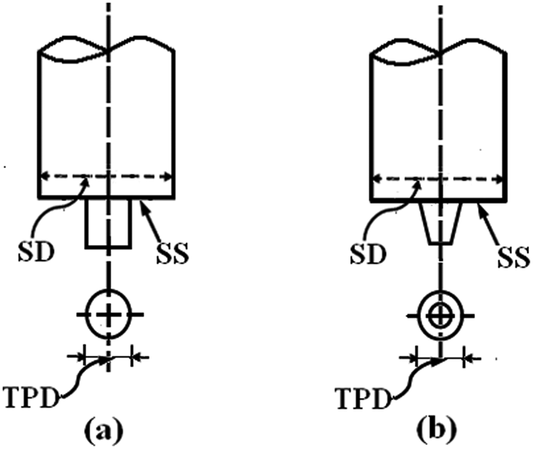
Schematic of FSW tools used in the experiment indicating shoulder diameter (SD), shoulder surface (SS) and tool probe diameter (TPD): (a) tool with cylindrical probe; (b) tool with tapered cylindrical probe.
Tool and experimental condition.
Model description
The Eularian finite volume CFD solver “FLUENT” was used, with the implicit formulation for the investigation. It can be said that FSW is a high-speed non-homogeneous forming process similar to material extrusion and forging. Thus, the flow in the process can be treated as flow of visco-plastic material. 14 As the instantaneous flow region around the tool is small in FSW, the physical size of the computational model was kept intentionally small compared with the work piece to reduce the simulation time. In the present model the computational region was assumed to be a fluid plate of AA 1100 of size 60 × 60 × 6 mm where 6 mm is the thickness of the plate with the FSW tool located at the center. The surrounding plasticized material moves with a uniform velocity with welding speed U 1 in the direction of welding towards the rotating tool, which rotates anti-clockwise with an angular velocity ω as shown schematically in Figure 3. As discussed above, the relative motion between tool and work piece was simulated by keeping the tool stationary and moving the work piece. The mesh geometry for each tool and work piece were created using ANSYS GAMBIT. The meshing and the model were then exported and loaded in FLUENT solver. While generating grids for these mentioned domains, it was ensured that the mesh was refined in the vicinity of the pin tool surface and expanded gradually away from it. It was done owing to a large temperature gradient in the vicinity of the pin tool to achieve adequate grid resolution for accurate temperature prediction. Tetrahedron elements were used for the volume meshing purpose. The CFD model geometries with meshing for different tools are shown in Figure 4. Convective heat transfer to the surround was assumed for the plate vertical sides (S1, S2), plate top surface and tool shank’s cylindrical region above the plates. The conduction of heat between the work piece and tool was also considered. But heat transferred to the supporting table was ignored. The total heat input at the interface of the tool–work piece was determined, as defined by Schimdtand Hattel. 12 Partial stick–slip conditions were introduced in the present model and the material was considered to be isotropic. The CFD solver condition was set to segregate, implicit, laminar and steady.
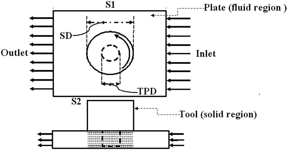
Schematic of standard set-up of the computational model.
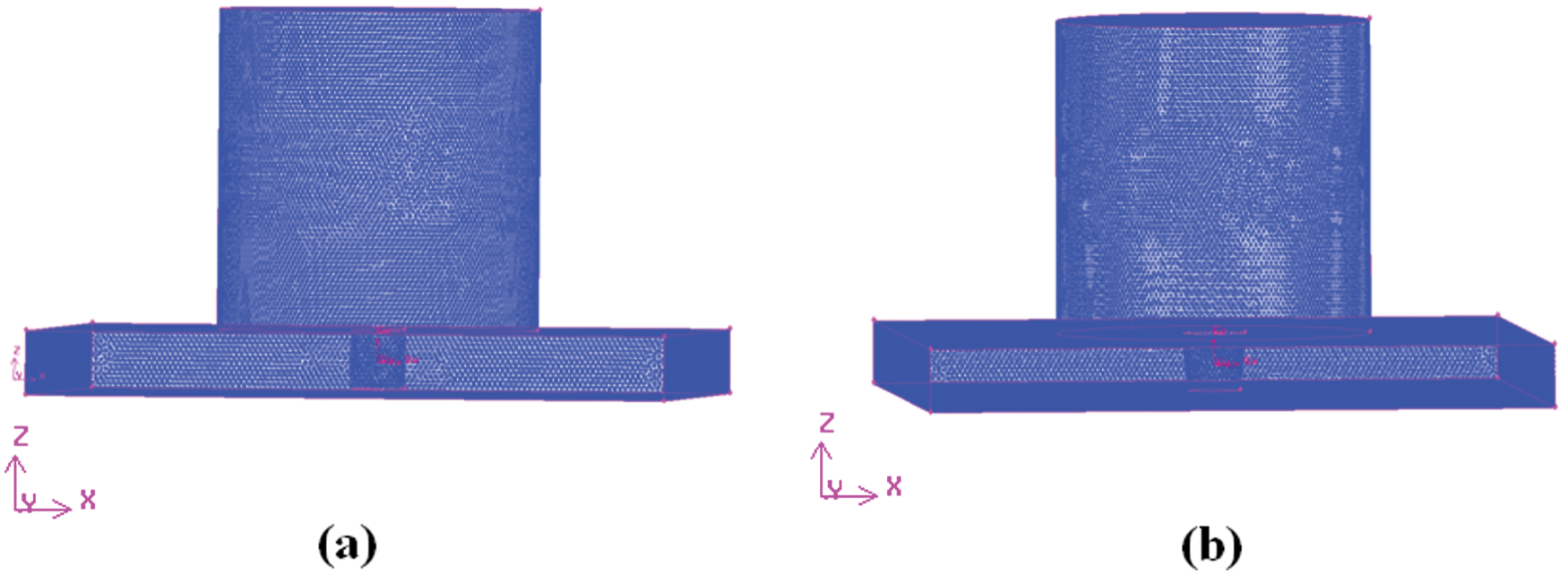
Meshing and models of (a) straight cylindrical; and (b) tapered cylindrical tool domains.
Governing equations
The continuity equation for incompressible single phase fluid can be written as

where
The momentum conservation equation, with reference to a heat source, can be stated by

where ρ is the density, P is the pressure, µ is the non-Newtonian viscosity and U 1 is the welding traverse velocity.
The temperature distribution is obtained by solving the steady thermal energy conservation equation given by
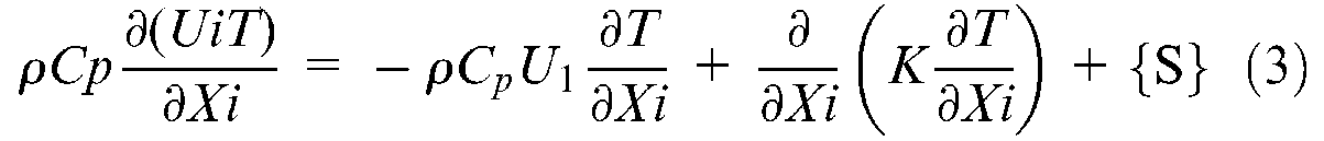
where
In the present analysis, the temperature-dependent thermal conductivity and specific heat coefficients for AA 1100 were used, as given in Table 2. 16 The FLUENT software permits the user definition of a complex material viscosity model and boundary conditions. In FSW, TMAZ can be considered as a rigid visco plastic fluid and works at a temperature reasonably below the material solidus temperature. Owing to the existence of a high strain rate in the stirring zone around the tool pin and low strain rate outside the stirring zone, a Carreou viscosity model was introduced in the present investigation, as done by Atharifar et al. to take care of non-linear viscosity behavior of weld material in computational zone.14,17
Temperature dependent material properties of work material. 16
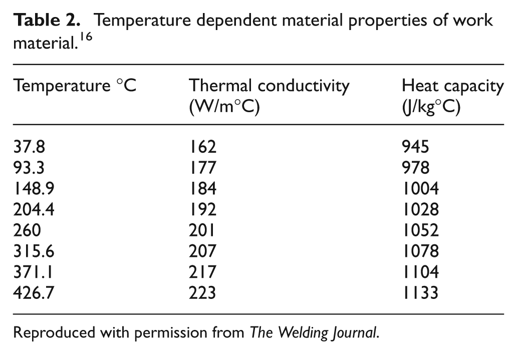
Reproduced with permission from The Welding Journal.
The viscosity and velocity gradient can be determined from the solution of the momentum conservation equation (2). Temperature dependent martial properties like specific heat (C p ) and thermal conductivity of the material (K) were included in the energy equation (3). Therefore, both mechanical and thermal boundary conditions were fully coupled and solved simultaneously in FLUENT in an iterative manner.
Boundary conditions:
Convective heat losses to the surrounding on the top surface and vertical sides (S1,S2) of the fluid plate region were assumed with a convective heat transfer coefficient of 20 W/(m2.K) and heat transfer coefficient of 100 W/(m2.K) was assumed for the exposed surface of the FSW tool. The inlet velocity boundary condition in the model was set equal to the welding traverse velocity (U1) and the outlet boundary condition was considered as outflow only. The initial temperature of the model was assumed to be at 27 °C.
As defined by Schmidt and Hattel, 12 the partial sliding–sticking condition was considered in the analysis. It was assumed that the shoulder region exhibits the contact conditions similar to sliding and the probe contact region closer to the sticking condition. This indicates the matrix segment accelerates to a velocity that is less than the tool surface velocity. For modeling, a dimensionless variable was defined as

where ω m and ω were angular velocities of the matrix and tool, respectively. δ was the contact state variable. The boundary condition of angular velocity for the tool was considered as the velocity of the matrix ω m by assuming state variable δ as 0.6.
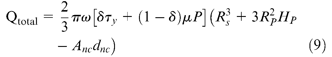
The analytical equation for heat generation at the contact interface between a rotating FSW tool and stationary work piece is given by 12

where Q is the heat generated by area A with the centroid distance d from the axis of rotation of the tool. τcontact is the contact shear stress located at the contact interface between the rotating tool and shear layer matrix. For sliding

where µ = coefficient of friction and the contact pressure P can be determined by dividing experimental axial force by horizontal tool area.


where Anc is the non-contacting area of shoulder (for concave shoulder surface), Rs is the radius of tool shoulder and θ is the inclusion angle of concave shoulder.
For the present contact condition (partial sticking–sliding) for the concave shoulder with cylindrical probe the Schmidt equation for total heat Qtotal can be modified as
In the case of the flat shoulder with the cylindrical probe the heat generation expression is simplified to
where τ
y
is the material shear stress equal to
The heat generation contribution from the different tool surface, compared with the total heat generation based on Schmidt analytical expression, were assumed to be 87% in the shoulder,8,12 10% in the probe side and 3% in the probe tip for all types of tools in the present study. The heat input to both models was obtained analytically from the above equation using data from Table 1 and applied as the boundary condition to the model as the heat flux in the tool–work interface. Longitudinal travel of the tool can be neglected as it is also reported that the tool travel contribution is only about 5% of the total heat for a 6 mm thick aluminum plate.
Results and discussions
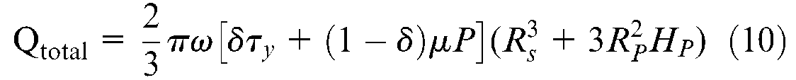
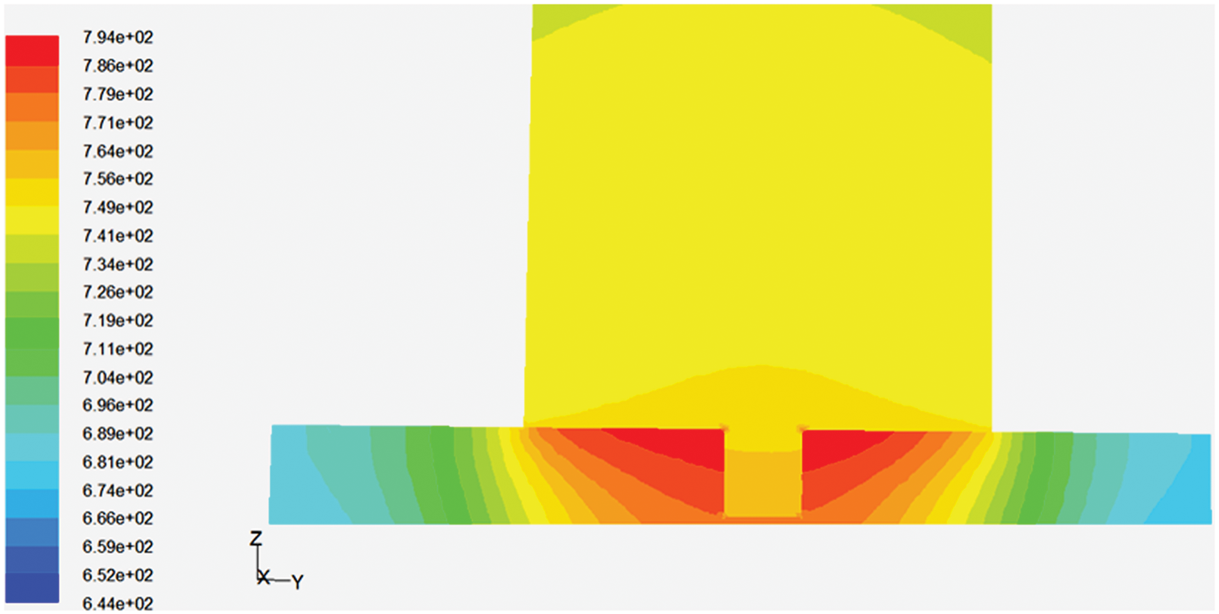
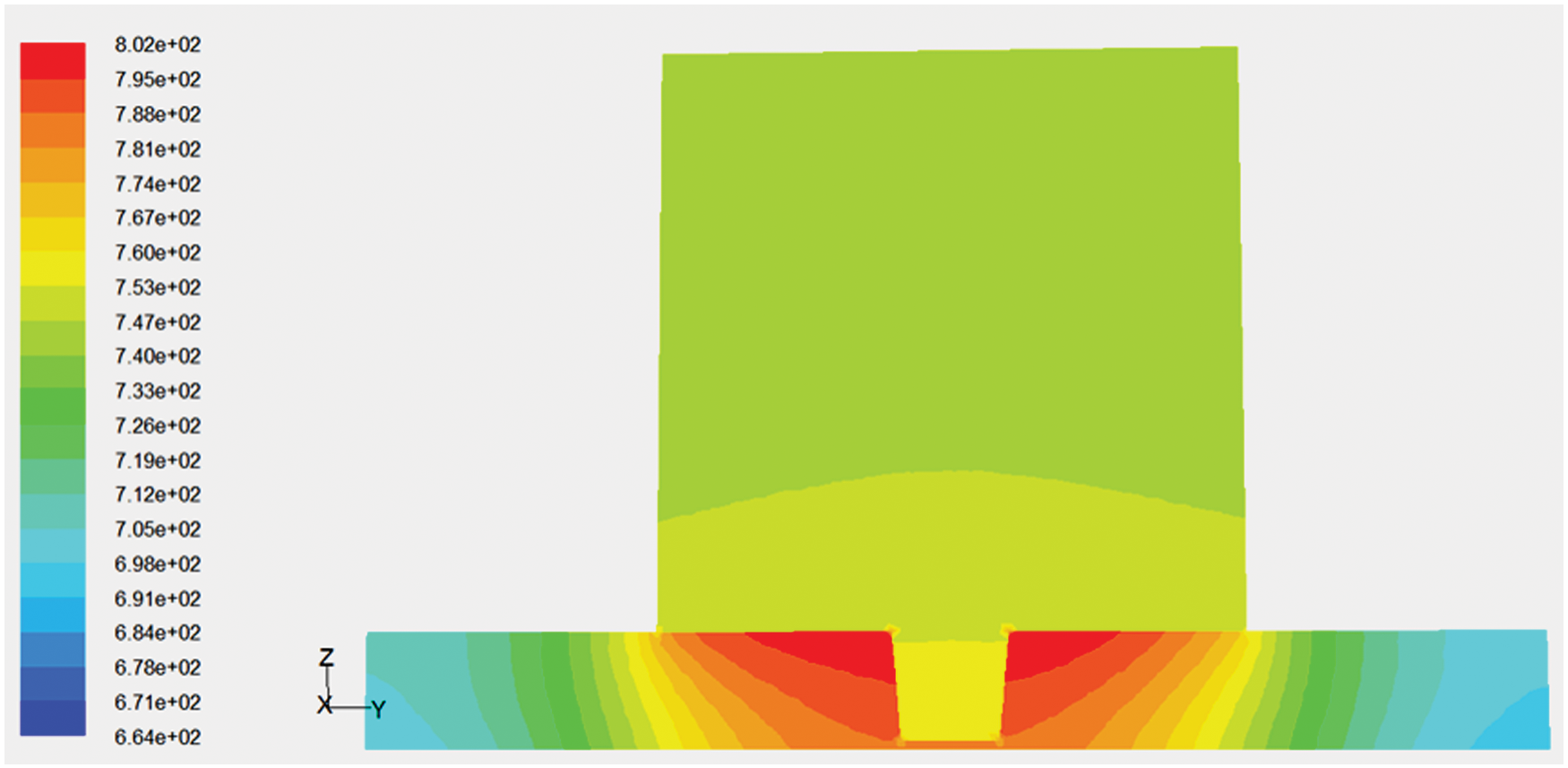
The variations of peak temperature distribution along the Y-axis, perpendicular to the weld interface for a straight cylindrical and tapered cylindrical pin are depicted in Figures 5 and 6, respectively. It is observed that the peak temperatures obtained from the result of thermal analysis of FSW of AA 1100 aluminum alloy is below the melting point temperature for both the tools. The peak temperature observed is about 85% of the melting point temperature of the material. Further, as expected, the tapered tool pin, of diameter 5–6 mm, led to a higher temperature than compared with the straight cylindrical pin of 5 mm diameter. It is owing to more surface contact area of tool probe with the metal matrix. The temperature was measured from the experiment on the top surface of the specimen at four different locations along the Y-axis. The measured temperature values are plotted and presented in Figure 7. The average cell temperature, at different locations along the Y-axis from the center of joint, was calculated for numerical modeling and plotted in Figure 7 for both the tools. It is observed that there is good agreement between experimental and numerical prediction. Further, the advancing side of the weld exhibits more temperature both numerically and experimentally than compared with the re-treating side, as shown in Figure 6. This behavior is owing to the higher heat generation rate in the advancing side because of the higher relative velocity between the tool and work piece. It is further observed that the temperature in the outer shoulder is less than the root of the pin shoulder indicating more slip. The temperature profile along the X direction, i.e. in the direction of welding for both the tools, is presented in Figure 8. It is observed that the temperature profile is compressed in front of the tool and expanded behind it. It is owing to the rapid heat supplied to the cold region of the work piece ahead of the tool and slower rate heat supplied to an already preheated zone behind the tool. The predicted velocity vector of material flow along the thickness (Z-axis) of the joint for a straight cylindrical tool is presented in Figure 9. It is observed that the shear layer is wider in the upper region owing to the effect of shoulder and material rotation with δωr owing to the partial stick–slip condition and more narrow at the root region is owing to the colder thermal condition leading to conical-shaped shear layer as shown in Figure 10. Further, the material flow path line at the work piece surface for the partial stick–slip condition, in which material is fed from right to left and the tool rotated in an anticlockwise direction, is presented in Figure 11. The model predicts that the material enters the advancing side of the shoulder region at the velocity of the welding speed, slows and then flows in the reverse direction near the advancing edge of the pin. The material near the pin diameter is pushed downwards at the back of the shoulder and is subsequently expelled in the weld region. Further, the material at the retreating side of the shoulder is not rotated with the tool, but simply extruded past the tool. As indicated in Figure 11, the material near the pin appears to rotate with the tool and the particle deforms around the retreating side of the pin extrude upward to fill the shoulder.
Modeled temperature counters in Kelvin scale (K) with straight cylindrical probed tool.
Modeled temperature counters in Kelvin scale (K) with tapered cylindrical probed tool.
Comparison of experimental and numerical temperature values in Kelvin scale (K) for: (a) straight cylindrical; (b) tapered cylindrical tools.
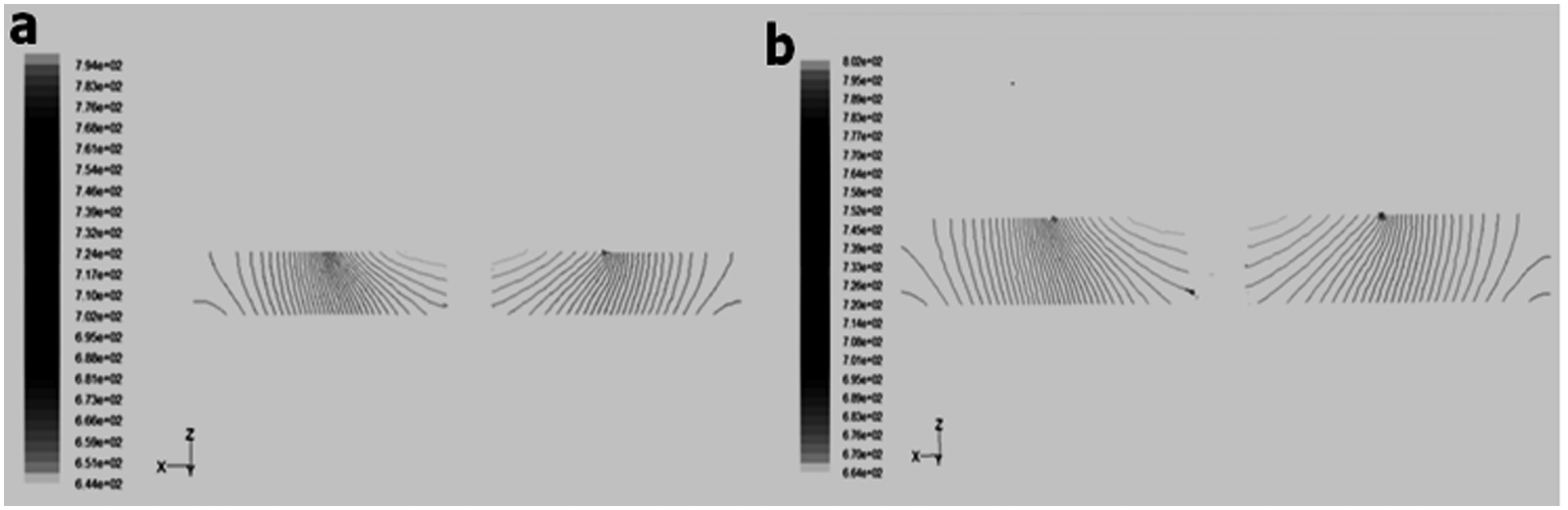
Temperature contours in Kelvin scale (K) of (a) straight and; (b) tapered cylindrical tools along the welding direction.
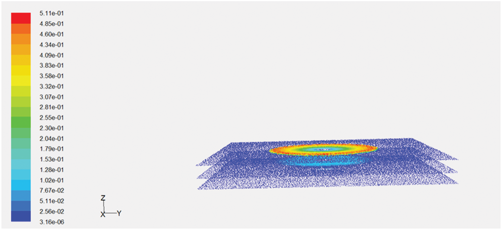
Material velocity (m/s) along the thickness for a straight cylindrical tool.
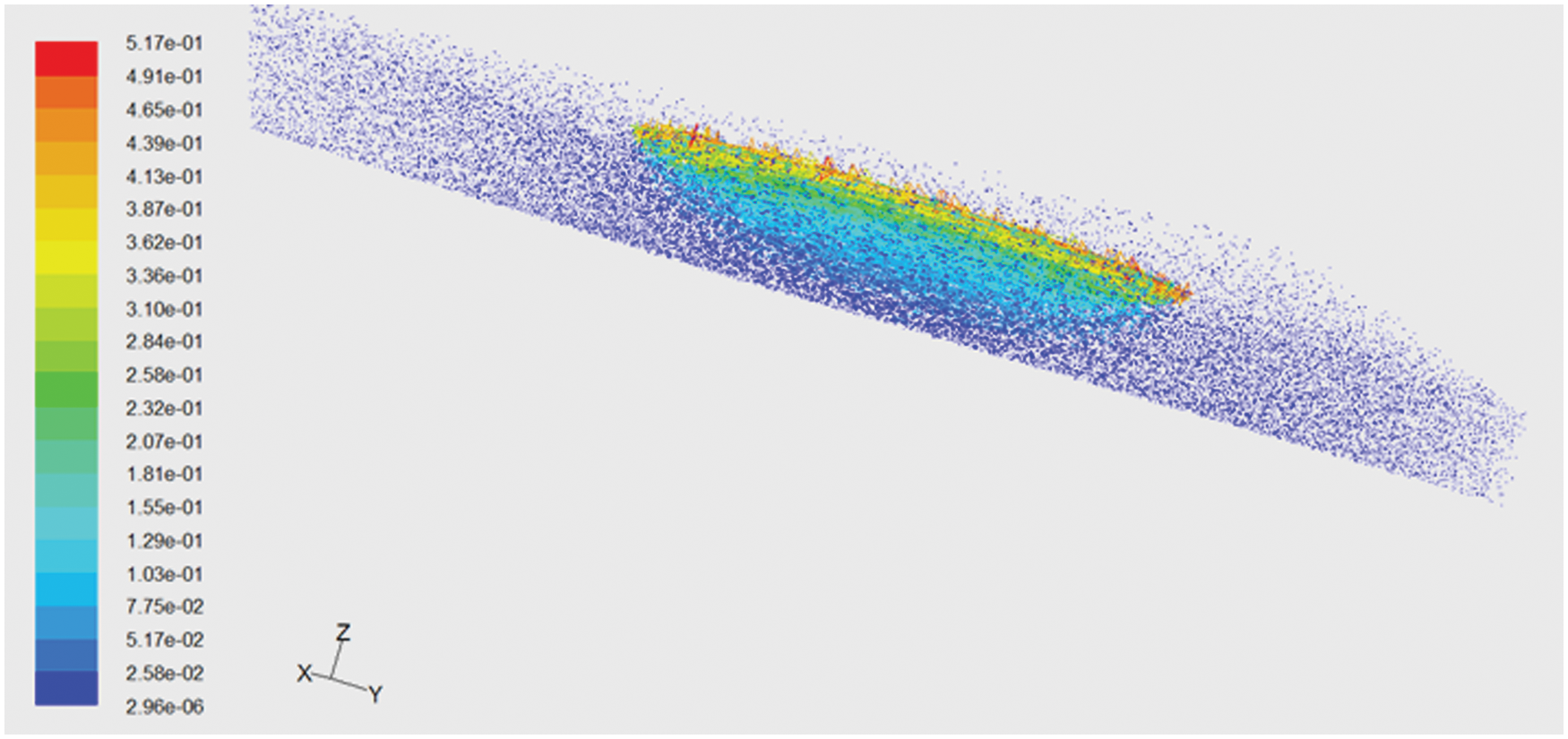
Material velocity (m/s) of the friction stir processing (FSP) zone for the tapered cylindrical tool.
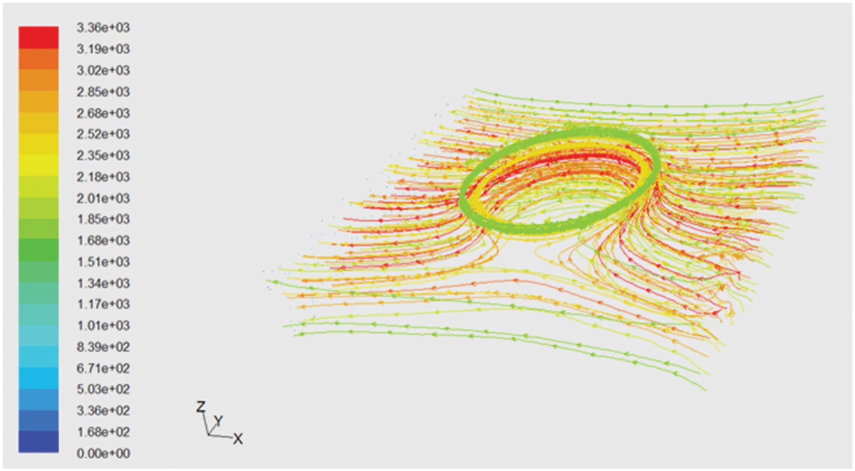
Model path lines of a straight cylindrical tool.
Conclusions
The present investigation effort to model the effects of tool geometries on material flow and temperature distribution indicated results that depict most of the features of FSW. The prominent features among the results are the difference between the advancing and retreating side of the weld. For both the straight cylindrical and tapered cylindrical tools, the temperatures at the advancing side were observed to be higher than that of the retreating side. Moreover, along the weld line, the temperature counters were observed to be more compressed ahead of the tools than the back side. The peak temperatures of 794 K and 802 K were observed for straight and tapered cylindrical tools, respectively. The peak temperatures measured by thermocouples, just at the side of the tool shoulders, closely agreed with the numerically predicted top surface temperature profiles. For both the tools, in the computational zones of the models, the maximum temperatures were observed to be less than the melting point of the material. Partial slipping and sticking conditions were observed for both the tools with wider shear layers at the top surface of the models, which gradually narrows down to the bottom of the joints. The gradual narrowing of the shear areas along the thickness provides the impression of weld cross sections. From the path flow lines of the model, it is observed that most of the material flow occurs in the retreating side. The amount of material that swept round the probes increased at locations closer to the shoulder. The assumptions utilized in the model, and the modeling methodologies adopted in the present investigation, were observed to be adequate in predicting the material flow and thermal conditions of the welds.
Footnotes
Acknowledgements
The authors thank the Department of Ocean Engineering & Naval Architecture, IIT Kharagpur for extending the FSW experimental facilities.
Funding
This research work has been supported by the Department of Scientific and Industrial Research (DSIR), India. The authors are grateful to DSIR for funding the work under TePP scheme.