
Abstract
The incremental sheet metal forming is a flexible process producing various parts with no need for dedicated dies. In this article, the upper-bound approach is used to study the deformation zone of single point incremental forming of truncated cones. The velocity field and the dissipated power of the process are achieved using an assumed deformation zone and streamlines defined by Bezier curves. The tangential force acting on the tool is attained by optimizing the presented upper-bound solution. Then, influences of the effective parameters including vertical pitch, initial thickness, tool diameter, and wall angle on the tangential force and the predicted equivalent strain are investigated. A strain hardening law is utilized to consider the work hardening behavior of sheet metals. In order to validate the presented upper-bound solution, predicted tangential forces are compared with experimental data reported in literature for forming AA3003 truncated cones. The comparison shows an appropriate agreement between experimental and predicted tangential forces.
Introduction
The utilization of traditional sheet metal forming processes, such as deep drawing for manufacturing parts, consumes time and money to prepare dedicated tools. In some cases, manufacturing a part with the least possible time and cost is necessary. In these situations, processes with simple tools and high performances are the point of interest. The incremental sheet metal forming (ISMF) process can be introduced as an appropriate choice to achieve these aims. In this process, in the simplest form, a hemispherical head tool is used instead of a milling cutter on a computer numerically controlled (CNC) milling machine. The periphery of a blank is fully fixed, then the hemispherical head tool incrementally forms the blank along a predetermined path generated using computer-aided manufacturing (CAM) software according to the desired shape (Figure 1). In this way, it is possible to form various shapes without dedicated dies for purposes of rapid prototyping. The ISMF process has some alternatives, among them the process described above called single point incremental forming (SPIF) depicted in Figure 1. An overview of incremental sheet forming patents and their technological developments can be found in Emmens et al. 1
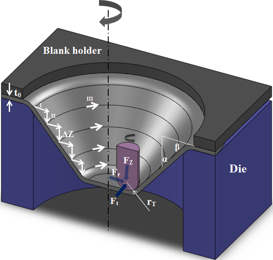
Typical presentation of single point incremental forming a truncated cone.
Besides the mentioned advantage, the formability of sheet metals can be improved using ISMF in comparison with traditional forming processes. The improvement of formability in ISMF has been proved by several experimental works. Shim and Park 2 studied the formability of aluminum 1050 sheet in ISMF. They indicated that forming limit curves (FLC) in ISMF has a distinct difference with traditional forming processes. The FLC is a straight line with a negative slope in the positive region of the minor strain. It is illustrated for different shapes that FLC in ISMF is higher than in traditional forming processes. For this reason, several researches on mechanisms of the formability improvement in ISMF are conducted. Ham and Jeswiet 3 studied the effect of the critical process parameters, including material type, material thickness, tool diameter, vertical pitch, and formed shape on forming limits using a design of experiment. Silva et al. 4 presented an analytical model based on membrane analysis for SPIF considering different deformation modes. They also concluded that neck formation is suppressed in SPIF, then fracture forming limit diagrams should be considered instead of traditional forming limit diagrams (FLDs). Through thickness shear in ISMF was experimentally investigated by Jackson and Allwood. 5 They studied the mechanism of deformation using copper sheets. Results showed the existence of shears in planes parallel and perpendicular to the tool direction, and mentioned that these shears are the main difference between the deformation mechanisms of ISMF and press working of sheet metal. Allwood and Shouler 6 and Eyckens et al. 7 modified the Marciniak–Kuczynski (M–K) model to consider the through thickness shear, and concluded that the through thickness shear can lead to the formability improvement. There are other mechanisms mentioned in literature for explanation of higher forming limits in ISMF. Several mechanisms that may enable stable deformation above the FLC in incremental sheet forming including shear, contact stress, bending under tension, cyclic straining, restriction of neck growth, and hydrostatic stress, have been discussed by Emmens and van den Boogaard. 8
One of the limitations of ISMF is the obtainable geometrical accuracy. Micari et al. 9 studied various sources resulting to errors and effective parameters on the dimensional accuracy. They concluded that the optimized tool path is an effective approach to reduce dimensional errors. Bambach et al. 10 formed a pyramidal part using multi-stage SPIF. It was shown that multi-stage forming can yield an increased accuracy compared with single-stage forming. They showed that a combination of multi-stage forming and stress-relief annealing before trimming the part can improve the geometric accuracy of the final part.
Since in ISMF the blank is incrementally formed to its final shape, at any moment there is a small deformation zone in the vicinity of the forming tool leading to lower forming forces than one in traditional forming processes, such as deep drawing. Also, unlike traditional forming processes, the size of the desired part does not effect the forming forces. However, prediction of forming forces is essential to design tools and to determine the necessary power of the machine. Iseki 11 obtained the forming forces for the incremental forming of the pyramid using a simply approximate deformation analysis. The plane strain deformation was assumed and this assumption was verified using a finite element method (FEM). Experimental results on aluminum sheet were in good agreement with those obtained by the approximate analysis and FEM. Filice et al. 12 utilized the gradient of tangential forming force to control the online ISMF for manufacturing AA1050-O truncated cones. Using statistical analysis they obtained a critical value for the gradient of the tangential force. Then they indicated that it is possible to control the online gradient of tangential force to be lower than the critical value by changing process parameters for preventing the fracture. Aerens et al. 13 studied the incremental forming of truncated cones of AA3003, AA5754, DC01, AISI304, and 65Cr2 using experiments and statistical analyses. They obtained regression formulae to predict the triple forming force components including axial, radial, and tangential components. These formulae are functions of wall angle, initial thickness, tool diameter, and vertical pitch. Finally, an approximate formula was deduced for predicting the axial component for forming any material based on the tensile strength only.
Unlike the above mentioned work for predicting the forming forces acting on the tool, in this article the tangential force required for SPIF of truncated cones is predicted using an assumed deformation zone and the upper-bound approach. Then the predicted deformation zone is presented. Influences of the most effective parameters, including vertical pitch, initial thickness, tool diameter, and wall angle on the tangential force and the equivalent strain are investigated. In this research, the upper-bound approach is introduced as an appropriate tool to predict the forming forces and the deformation zones in ISMF. In the presented upper-bound solution, the material behavior is assumed to be isotropic, while different material behaviors can influence the predicted tangential force. Generally, for simplicity, the Von Mises yield criterion is used in the upper-bound approach while using the FEM, one can consider other material behaviors easily (e.g. anisotropy, kinematic strain hardening, etc.). In this way, Flores et al. 14 and Henrard et al. 15 considered effects of different constitutive laws and yield conditions on predicted forces in SPIF of a cone, including tangential forces using finite element simulations. Henrard et al. 15 concluded that a proper accuracy can be achieved using a material model that combines the isotropic yield criterion of Von Mises with the mixed isotropic–kinematic hardening model of Voce–Ziegler.
Upper-bound analysis of ISMF
Figure 1 shows a scheme of SPIF for manufacturing a truncated cone, depicting the effective parameters. Here, the tool path is assumed to be circular depending on the amount of ΔZ at the end of each path. The forming forces acting on the tool are in axial, radial, and tangential directions. In this research, the deformation zone is first introduced. Then, the velocity field of the deformation zone, the strain rates, and the dissipated powers in the process are calculated.
The deformation zone of ISMF
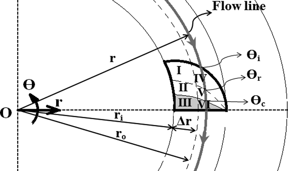
Figure 2 shows the deformation zone assumed in this research in the different views. The forming tool has a hemispherical head and the tool center is in ri off the centerline of the cone (Figure 2(a)). Figure 2(a) shows ISMF in two consecutive passes. If the feed rate of the tool center is equal to F, the sheet metal approaches the tool in the angular velocity of
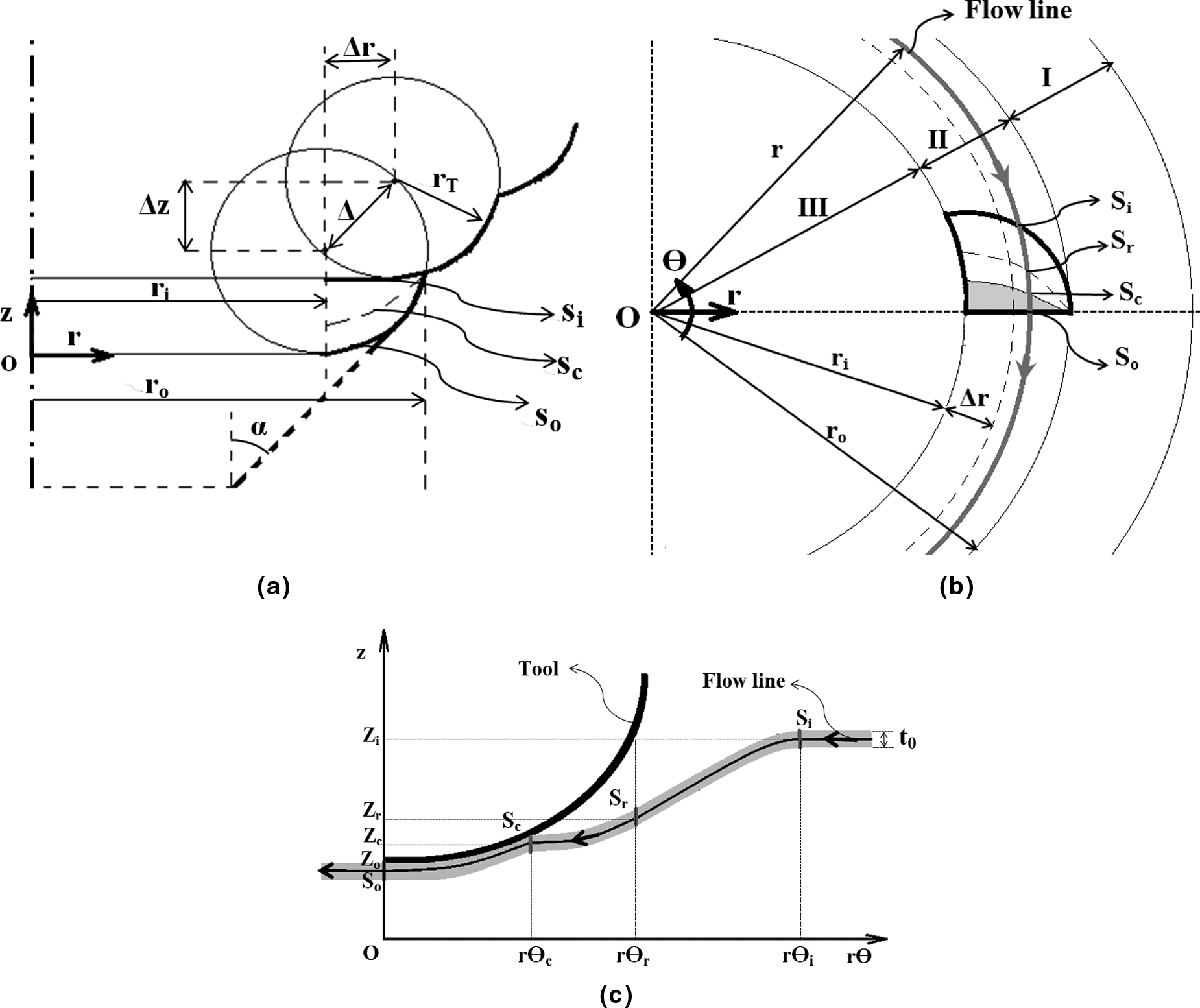
Deformation zone of incremental sheet forming: (a) r–z view, (b) r–Θ view, and (c) deformation of a streamline at rΘ–z view.
In the upper-bound analysis of shear spinning of cones proposed by Kim et al.,
16
it was assumed that the sheet metal is first bent and then starts to make contact with the tool. Similarly, here the deformation zone is assumed to be like Figure 2(c). According to Figure 2(b), when an element in zone II on a streamline with the radius r approaches the tool, after passing angle
According to Figures 1 and 2, the deformation zone is surrounded by ri, ro, si, and so, which are the interior radius, the exterior radius, the entry surface, and the exit surface of the deformation zone, respectively. The shaded area and the blank area of the deformation zone depicted by Figure 2(b) are the contact and the non-contact regions of the sheet with the tool, respectively. The entry surface si is assumed to be a circle with the radius (ro–ri) at the center of the tool head in the r–Θ plane. Since there are no thickness changes in the z direction, for simplicity “curves” can be used instead of “surfaces”.
The vertical component of sc (i.e. the contact position of the sheet with the tool) is unknown and is given as equation (1)

Where m is an unknown parameter obtainable using the optimization of the upper-bound solution. Accordingly zc is limited to values between the entry height zi and the exit height zo of the deformation zone.
According to Figure 2(c), the height variation of the streamline from the entry angle


where the vertical component of the tool head zT is obtained geometrically. The value of function

According to the research of Abrinia and Mirnia
17
for the streamlines in the equal channel angular extrusion (ECAE) process, Bezier curves are utilized here, since they can define easily using their control points and their characteristic polygons. Accordingly,
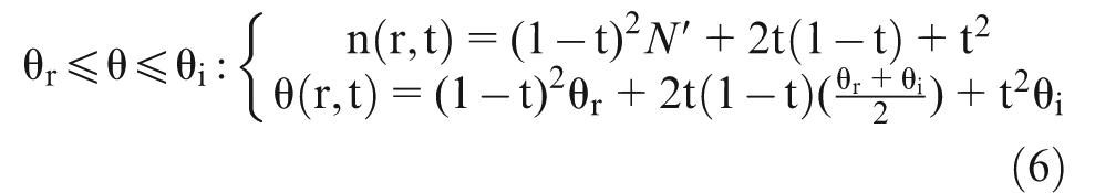
where
where

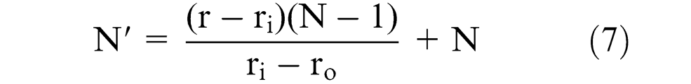
In equation (7), N is the other unknown parameter obtainable using the optimization of the upper-bound solution. Details for computing
Accordingly, the shape of a streamline in the deformation zone (see Figure 2(c)) is a function of m and N obtained by optimizing the upper-bound solution. In the present analysis the effect of friction is neglected owing to a small contact zone. Now, using the definition of the deformation zone and the streamlines, the velocity field can be computed, as described in the following section.
Velocity field of the deformation zone
Since there is no flow in the radial direction for a streamline at radius r, it flows only in the vertical and the circumferential directions, thus

If the feed rate of the tool head center is equal to F, the sheet metal rotates at angular velocity

For computing the vertical component of the velocity using equation (2), the following equation is obtained
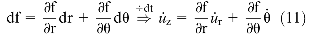
Therefore, by substituting equation (9) into equation (11) and as regards

Strain rates of the deformation zone
The strain rates in the cylindrical polar coordinates are defined as
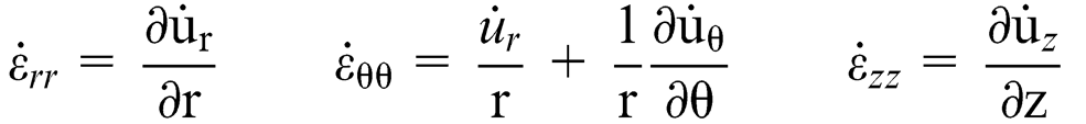
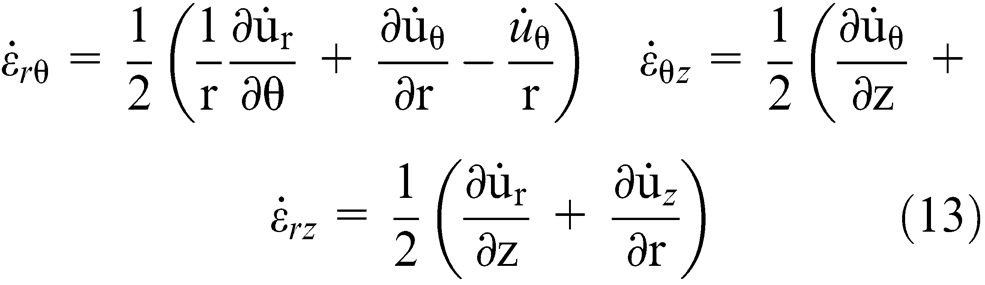
By substituting the velocity field into equation (13), the strain rates are obtained as


Power dissipated in ISMF
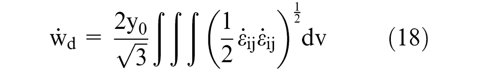
The dissipated power during ISMF computed using the strain rates can be expressed as

where
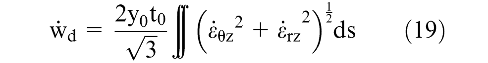
For computing the above equation, the deformation zone is divided to six sub-regions, as shown in Figure 3 owing to the discontinuity of equation (2).
Divided deformation zone.
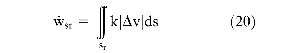
Regarding the assumed deformation zone, surface sr is the only discontinuity surface as shown in Figure 4. Therefore,
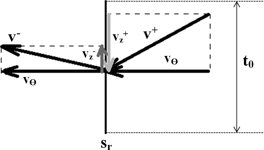
Velocity discontinuity on shear surface sr in thickness direction (
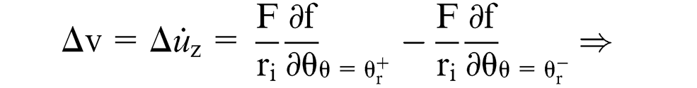
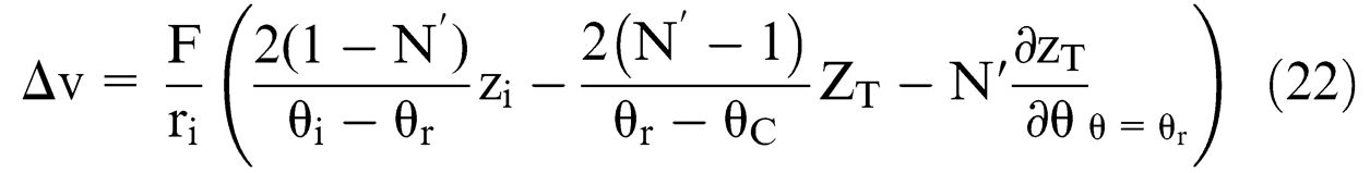
Then by rearranging

The velocity discontinuity on the surface sr in the vertical direction is equal to
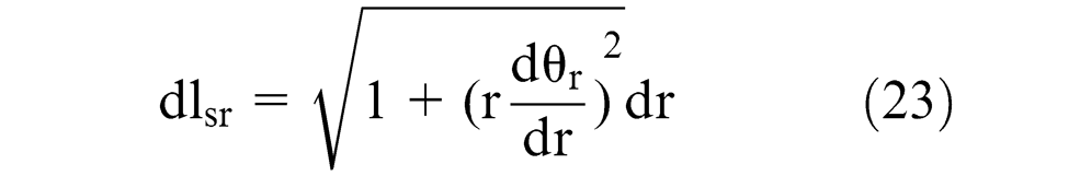
The length element is given as
In the above equations the shear strength k is equal to

Equivalent strain
The equivalent strain induced in an element on a streamline is computed using the strain rates. Then an average equivalent strain is introduced. Finally, using this average equivalent strain, the average yield strength is obtained for work hardening materials.
The equivalent strain is given as

where

where dT is the time element. The length element of the streamline in (r,Θ) coordinates

therefore, dT is given by

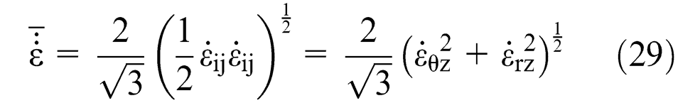
Also, the equivalent strain rate is given by
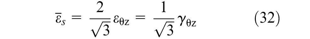
On the surface sr the shear strain

The equivalent strain is given by

By substituting equation (30) into equation (31)
Equation (25) is expressing the equivalent strain for a streamline at radius r. Hence, the average equivalent strain is given as

Equation (33) is expressing the average equivalent strain induced in sheet metal in a pass (i.e. a complete circle path).
By assuming the swift type work hardening law

where
Optimization of the upper-bound solution
Equation (17) expresses the dissipated power in ISMF. This expression is the function of two optimizing parameters m and N. By varying these parameters in their defined range (i.e.

Then it is assumed that the tangential force is acting at radius

Results and discussion
The tangential force necessary to form a truncated cone is computed using the optimization of the upper-bound solution proposed in the previous section. Then the shape of the deformation zone is obtained by two optimizing parameters m and N. Regarding to the upper-bound solution, the effective parameters on the tangential force are vertical pitch
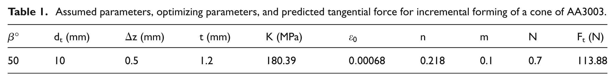
It is assumed that a cone of AA3003 sheet is formed using SPIF. The above mentioned parameters are assumed as Table 1. Also, the swift work hardening law obtained by Aerens et al., 13 and the tangential force predicted by optimizing the upper-bound solution, are shown in Table 1. Now, the shape of the deformation zone is obtained using two optimizing parameters m and N as shown in Figure 5.
Assumed parameters, optimizing parameters, and predicted tangential force for incremental forming of a cone of AA3003.
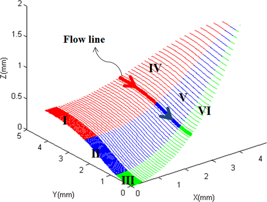
Deformation zone predicted using upper-bound for incremental forming of AA3003. Process parameters are β = 50°, dt = 10 mm, Δz = 0.5 mm, and t0 = 1.2 mm.
The six sub-regions shown in Figure 5 are the same as shown in Figure 3. Figure 6 shows the deformation zone depicted in Figure 5, in three views. It is notable to comprise Figure 6 with Figure 2. Each line in Figures 5 and 6 is a streamline. Hereafter the value of the four effective parameters are the same as the one mentioned previously, only if variations are mentioned.

Deformation zone relevant to Figure 5 in three different views. Each curve is a streamline.
Parameters study on the tangential force
Figure 7 shows the variations of the tangential force with the vertical pitch predicted by the upper-bound solution and compared with the experimental values reported by Aerens et al.
13
For all vertical pitches, the theoretical values are more than the experimental values. The more the vertical pitch, the larger the deformation zone. Hence, the tangential force reaches higher values. By increasing
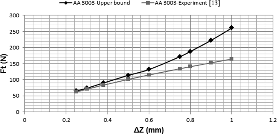
Variations of the tangential force with the vertical pitch obtained by the presented upper-bound solution and experimental work of Aerens et al. 13 Process parameters are β = 50°, dt = 10 mm, and t0 = 1.2 mm.
Figure 8 shows the tangential forces predicted using upper-bound and those experimentally obtained by Aerens et al.,
13
for various wall angles. According to Figure 8, the predicted forces show a minimum value for
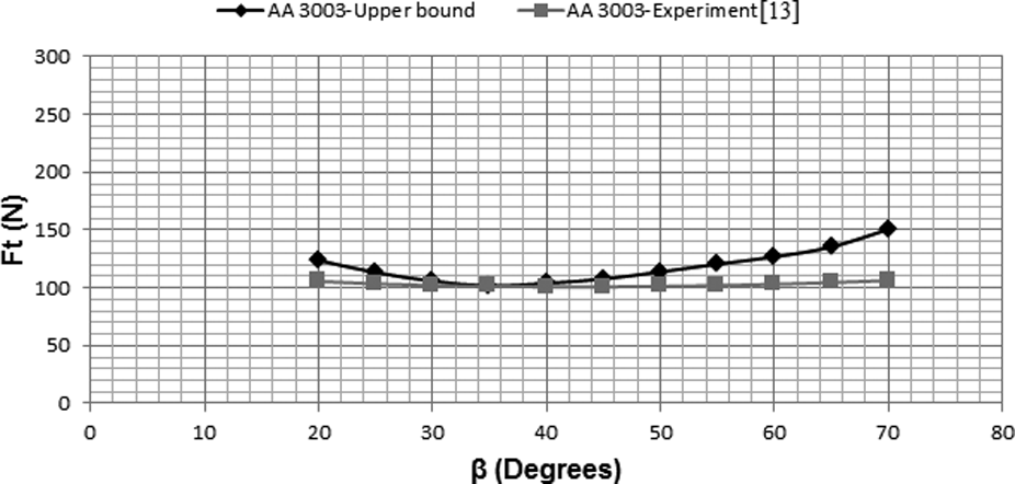
Variations of tangential force with wall angle obtained by presented upper-bound solution and experimental work of Aerens et al. 13 Process parameters are dt = 10 mm, Δz = 0.5 mm, and t0 = 1.2 mm.

Deformation zones predicted using upper-bound for wall angles 20°, 40°, and 60°.
According to Figures 7 and 8, the upper-bound solution based on the assumed deformation zone is in proper agreement with the experiment reported by Aerens et al. 13 Hence, influences of the effective parameters on the tangential force and the equivalent strain can be evaluated using the upper-bound solution.
Variations of the tangential force with the forming tool diameter for various vertical pitches are shown in Figure 10. These curves show a minimum. For a fixed vertical pitch, by increasing the forming tool diameter, the deformation zone becomes larger and results in higher forces, while by decreasing the forming tool diameter from one showing the minimum, the contact zone between the tool and the sheet becomes larger and results in higher forces owing to severe shear strains. Figure 11 shows that a small tool diameter compared with a vertical pitch results in a severe shear deformation. By increasing the tool diameter, the deformations become moderate and lower forces are achieved. But the larger tool diameter results in a wider deformation zone and subsequently the tangential force reaches higher values.
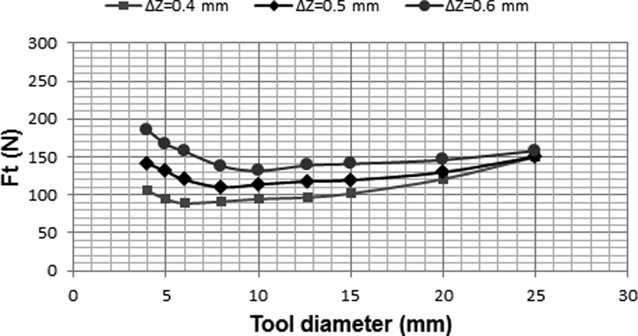
Variations of tangential force with the forming tool diameter for various vertical pitches.

Comparison of the deformation zone predicted using the upper-bound solution for two tool diameters.
Using Figure 10 it can be concluded that the tangential force always remains at a minimum for a constant parameter named R and defined by
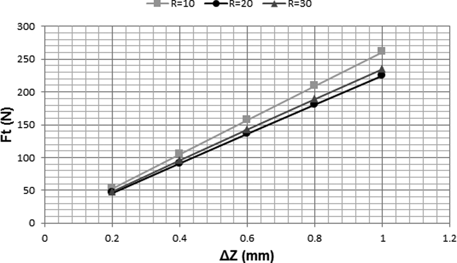
Variations of tangential force with vertical pitch for various
As shown in Figure 13, the tangential force increases linearly with an increase in initial blank thickness since the material volume under deformation becomes larger.
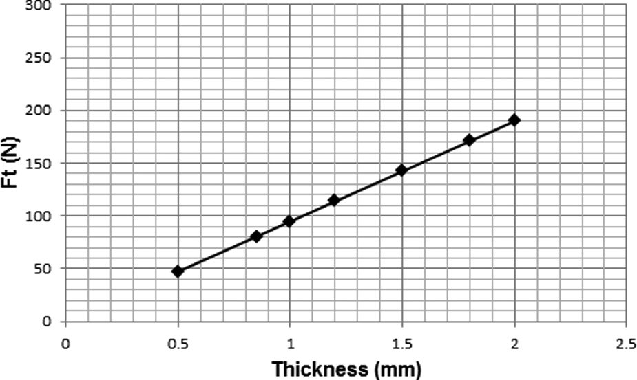
Variations of tangential force with initial blank thickness.
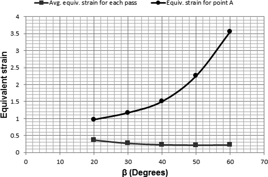
Parameters study on the equivalent strain
Using equation (25) the equivalent strain distribution can be obtained. Influences of the effective parameters on the average equivalent strain induced in one pass
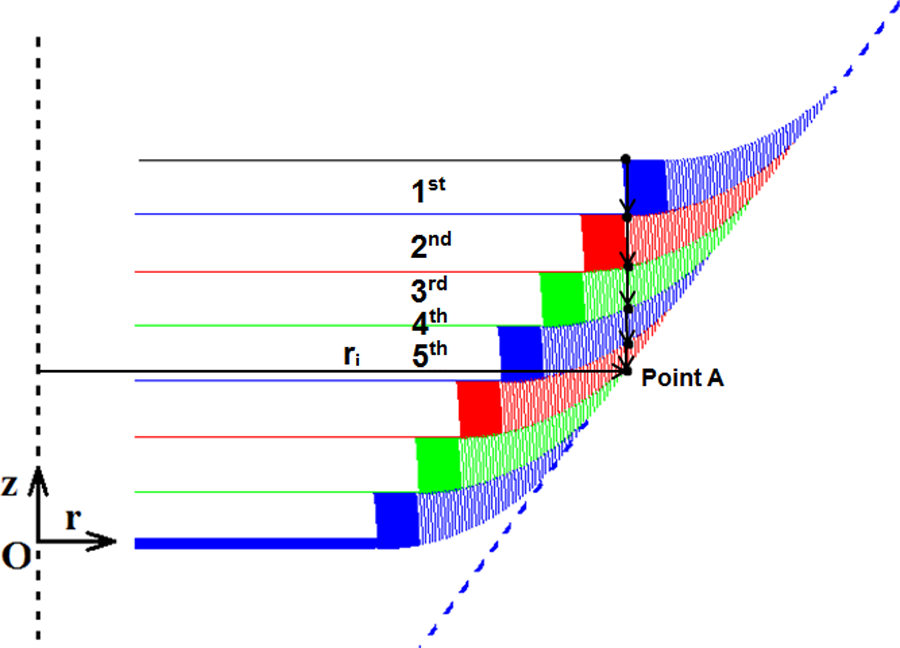
A number of sequences necessary to form point A placed at ri from the centerline.
Variations of
Variations of
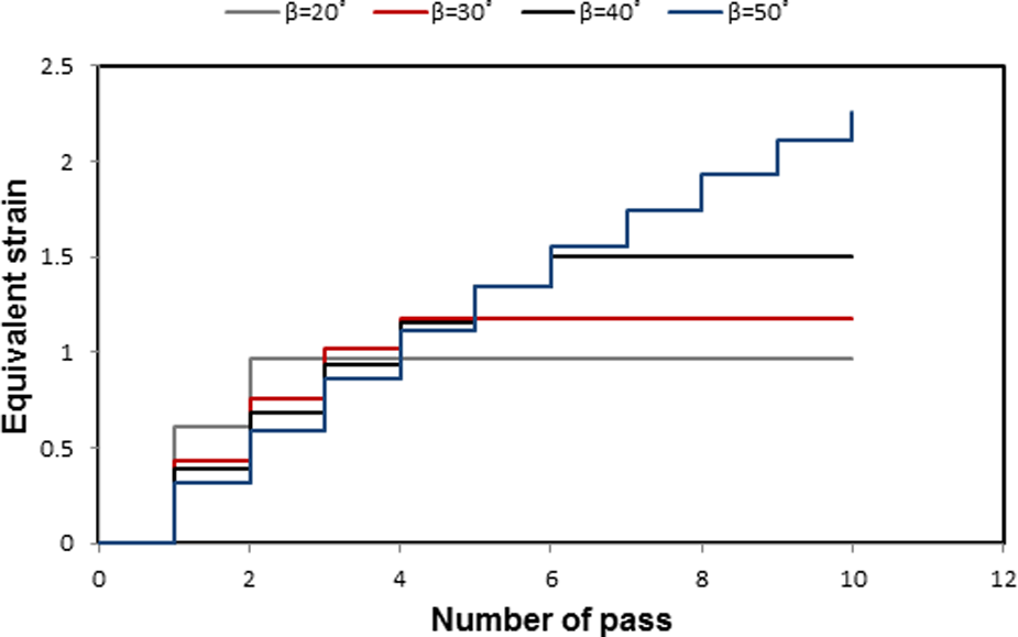
The increase of
An increase in Δz, increases
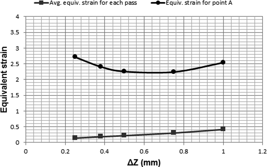
Variations of
By increasing the forming tool diameter,
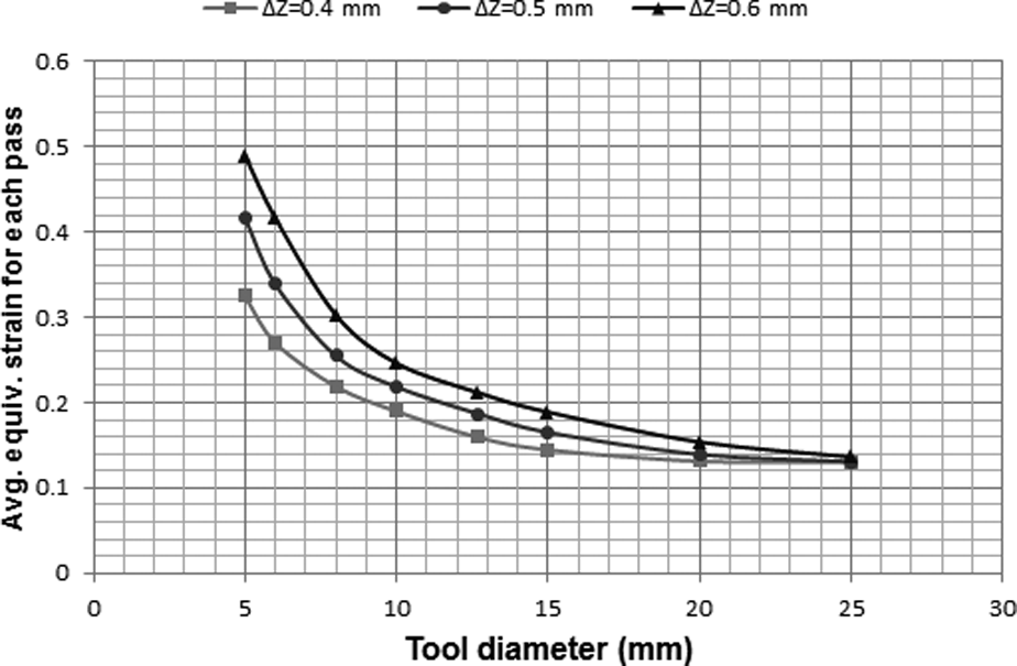
Variations of
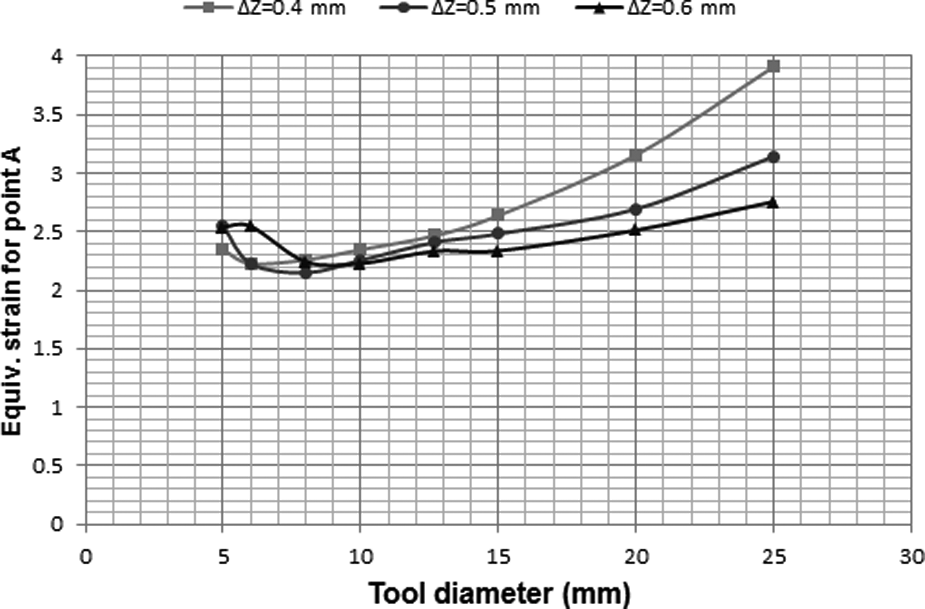
Variations of
It can be concluded from Figure 20 that a simultaneous increase in the vertical pitch and the tool diameter (i.e. at constant R) has no effect on
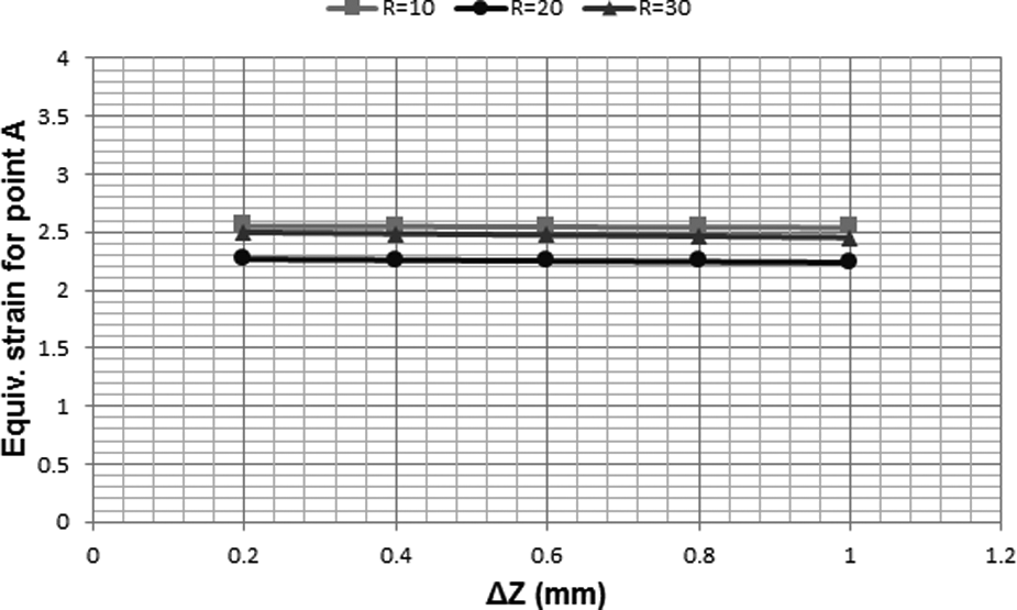
Variations of
Conclusions
In the present article, for the first time, the SPIF of a truncated cone was studied using the upper-bound approach. In the presented upper-bound solution a deformation zone was introduced using assumed streamlines defined by Bezier curves. By optimizing the upper-bound solution, the deformation zone, the tangential force, and the equivalent strain was predicted for forming a truncated cone from a known material based on the predetermined values of the vertical pitch, the tool diameter, the sheet thickness, and the wall angle. The following was concluded.
Based on the variations of tangential force with vertical pitch, a good agreement was found between the present upper-bound solution and the experimental results for vertical pitches lower than 0.6 mm (the mean difference is 9%). Also, according to the variations of the tangential force with the wall angle, a reasonably good agreement was found for wall angles lower than 60°, at which the mean difference is 10%.
By increasing the vertical pitch, the tangential force increases as the larger deformation zone is formed. Also, it was shown that the more the thickness, the higher the tangential force.
By increasing the wall angle from 20°, the tangential force decreases and then increases to form a larger deformation zone.
The tangential force becomes smaller as the tool diameter increases from 4 mm and by further increase of it, the tangential force increases. Also, it was concluded that a ratio of the tool diameter to the vertical pitch (i.e. R) can be obtained to minimize the tangential force.
For determining the total equivalent strain of a point on the wall, the number of forming passes necessary to form the point, and the equivalent strain induced in each pass, are to be considered simultaneously.
There are other tool paths where a sheet can be formed to a non-circular shape using SPIF. Such a tool path is seen in SPIF of a truncated pyramid in which a sheet is formed using straight paths in the z-plane except at corners. The model presented here can be applied to this kind of tool path easily by defining the deformation zone and streamlines in a Cartesian coordinate instead of the polar coordinate (equation (2)). Also, the sheet metal approaches the tool at a feed rate instead of an angular velocity.
In future work, using a modification of the presented upper-bound solution and the geometrical characteristics of the deformation zone, the vertical and the radial components of the forming force will be predicted and will be verified by experiments.
Footnotes
Appendix
Funding
This research received no specific grant from any funding agency in the public, commercial, or not-for-profit sectors.