
Abstract
High thermal loads during the cutting process can have a major influence on tool performance. Multilayer coated tools can have a positive impact in improving machining performance, especially at high cutting velocities. In this study TiCN/Al2O3/TiN, TiCN/Al2O3 and TiCN/Al2O3–TiN multilayer chemical vapour deposition (CVD)-coated carbide cutting tool inserts, were investigated in dry turning of AISI/SAE 4140 over a wide range of cutting speeds of between 200 m/min and 879 m/min. While the TiCN/Al2O3/TiN and TiCN/Al2O3 coating layers were deposited uniformly around the insert, TiCN/Al2O3–TiN has TiCN/Al2O3 on the rake face and TiCN/Al2O3/TiN on the flank/clearance faces. For clarity, in this article it is addressed as (TiCN/Al2O3/TiN)flank (TiCN/Al2O3)rake and termed the functionally graded system. The investigations were based on experimental determination of cutting forces, chip compression ratio, tool–chip contact phenomena, and flank wear, as well as finite element modelling of heat partition into the cutting tool. Results show that two layered TiCN/Al2O3 deposited in series gives a better performance against the three layered TiCN/Al2O3/TiN and the functionally graded TiCN/Al2O3–TiN tools. Results from the cutting tests and finite element analysis suggest that selection of an appropriate top coating and optimised coating thickness are two important factors for achieving effective cutting performance.
Introduction
The current trends in high-speed machining (HSM) are driving cutting tool researchers and manufacturers towards the exploration of effective design of multilayer coated tool systems. This includes development of new coating compounds and deposition techniques, as well as optimisation of coatings by considering the sequence of coating deposition, thickness and layouts according to required functional attributes.
More common deposited coatings on commercially available tools are; titanium carbide (TiC), titanium nitride (TiN), titanium carbonitride (Ti(C, N)), aluminium oxide (Al2O3) and titanium aluminium nitride ((Ti, Al) N),1,2 to name a few. These have proved to be effective when exposed to severe cutting conditions incurred during HSM. Among these, a TiN coating is widely deposited on commercial tools owing to its favourable response against higher mechanical and thermal stresses. Its poor adhesion to steel workpiece materials and lower coefficient of friction3–5 are the key functional benefits for its continuing use as a top layer in multilayer coated tool systems.
Another coating whose presence in the coating systems can be effective is Al2O3. The unique thermal properties of Al2O3 at elevated temperatures have enabled its exploitation as an intermediate or top layer in a multilayer coated tool system. The thermal conductivity of Al2O3 decreases with an increase in temperature. 6 Also, when used in a multilayer coated system, Al2O3 reduces the equivalent thermal conductivity of the coating system as a whole, 6 and hence reduces heat penetration into the cutting tool. Some of the main advantages of an Al2O3 layer in a coating tool system include; effective chip curl and hence its breakability 7 as more heat is diverted into the chip, and extended tool life owing to excellent hot hardness. Furthermore, its ability to impede diffusion, 8 reduce contact length, and hence, limited heat distribution into the cutting tool. 9
Other coatings include TiC, TiCN and TiAlN, which are generally deposited as a first layer (adjacent to the substrate) in a multilayered coated tool system due to their strong adhesion to the substrate. 10 The crack propagation, which is a critical issue in the coating systems at higher temperatures, can be alleviated by depositing these coatings. Such coatings (in combination) inhibit crack initiation when fatigue stresses are produced with the frequent formation and removal of the chip material that adheres to the cutting tool rake face. 10
The deposition sequence of the coating systems is generally in series (i.e. layer by layer). Nowadays, by taking advantages of functional attributes (i.e. thermal shielding, lower coefficient of friction and self lubrication at higher temperatures) of different coatings, commercial tools can be selectively deposited on the rake face and the flank face, as appropriate. These are generally referred to as functionally graded coated tools. 11
Although there have been several studies conducted on multilayer coated tools,12–16 where the coatings were deposited in the laboratory, there are still outstanding issues that are crucial for commercial tools. These include early chipping of the cutting tool edge and rapid wear resulting in shorter tool life.
For decades, among other methods, finite element (FE) modelling has been successfully used to investigate the thermal aspect of cutting process. Tay et al. 17 developed a two-dimensional (2D) FE model for orthogonal turning of free machining steel. They applied the FE method to calculate the temperature fields generated in the workpiece, chip and tool during orthogonal machining using experimentally obtained flow fields together with measured cutting forces as an initial input. In another investigation Adil et al. 18 conducted FE modelling to investigate the temperature distribution in the cutting domain (i.e. tool–chip–workpiece). The model was applied on longitudinal turning, taper turning and facing operations and validated to the previously reported results. It was deduced from the study that the pattern of the temperature profiles on the rake and flank face, for all three kinds of machining, were similar.
Lin 19 conducted an inverse FE analysis with the measured temperatures on the machined surface to evaluate tool face temperature and heat dissipation into the workpiece during the milling operation. It was concluded that thermal properties, specifically thermal diffusivity, is influential in evaluating average tool temperature and heat partition into the workpiece material. Fang et al. 20 conducted a FE analysis to study the formation mechanism of the adhering layer on the tool rake face on the basis of temperature distribution. Temperature distribution at the tool–chip contact region was taken as the boundary condition to study the cutting tool temperature field.
Ramesh et al. 21 carried out a study using FE modelling with steady state 2D and 3D models for heat transfer analysis in machining of isotropic materials. The effect of the heat transfer coefficient in machining was highlighted. The numerical model was developed and verified by using previous experimental and empirically predicted results. Using these, tool–chip temperatures profiles were predicted. It was concluded that the effect of the depth of cut on the rake face temperature is only marginal and the effect of feed and cutting speed on temperatures are significant. Akbar et al. 13 investigated the heat partition coefficient in machining. The transient heat transfer problem was simulated using commercially available FE software Abaqus/Standard. The tool was modelled as a perfectly rigid body, and uniform and non-uniform heat flux is applied on the tool–chip contact area, which was evaluated using experimental data.
In a recent article, Tang et al. 22 conducted a study using FE modelling to predict the influence of cutting speed and depth of cut on temperature fields and residual stresses. A thermo-mechanical FE modelling was conducted for the machining of AISI D2 hardened tool steel using commercial code Abaqus/Explicit. It was deduced that FE can be conveniently used in industry to analyse and predict the effect of cutting parameters on the cutting mechanism.
As discussed earlier, heat loads produced during the cutting process is an important issue, which, if not controlled, may lead to premature tool failure. Therefore, it is important to evaluate heat distribution into the cutting tool. Most of the studies conducted for the evaluation of heat partition/heat distribution are generally based on the orthogonal turning process. Other types of machining processes, for example accelerated cutting, could induce temperature rise and rapid wear. Previous studies5,13,14 have shown that the contact area, tool material thermal conductivity and secondary zone heat generation dominate heat partition to a greater extent than temperature rise. Rapid wear would produce an increased heat flux if it is associated with an increased non-sporadic contact area. However, the contact area may be irregular owing to wear patterns, and hence, the effect of rapid machining and rapid wear to heat partition can be wear pattern depended.
Evaluation of heat partition into the cutting tool, chip or workpiece material may not be evaluated by means of experimental techniques alone. Therefore, generally, researchers use a FE method along with experimental data to estimate/evaluate heat partition in the cutting domain. Abukhshim et al. 14 conducted an investigation on heat partition during HSM when cutting high strength alloy steel with flat rake face cemented carbide tools. A wide range of cutting speeds between 200 and 1200 m/min were tested. They considered a uniform heat flux at the tool–chip contact area for FE simulation and the model (FE) was validated by comparing simulated and experimentally measured temperatures at a single point. The study revealed that heat partition into the cutting tool insert decreases (from 48% to 15%, approximately) from conventional to transition cutting speeds, but increase (from 15% to 68%, approximately) in a HSM regime.
Akbar et al., 13 in their study, applied a non-uniform heat load on the tool–chip contact area for the investigation of machining of AISI 4140 with uncoated and single-layer coated tools (WC, TiN and TiAlN). The study revealed that, in the case of uncoated tools, heat partition from conventional to transitional cutting speed decreased (from 41% to 16.5%) and then increased (from 16.5% to 23.5%). In case of single-layer coated tools there was a continuous reduction in the heat partition as the cutting speed increased. For TiN coating, the reduction from conventional to high speed (100–880 m/min) was 35% to 9.5%. For TiAlN the heat partition values from conventional to high speed (100–880 m/min) were 38% to 9.2%. Recently, Fahad et al. 7 used combined FE modelling and experimental data to evaluate heat partition into a functionally graded coated tool. It was reported that heat dissipation into the cutting tool can be 4.4% at a cutting speed of 879 m/min when machining AISI 4140 using functionally graded restricted contact coated tools.
It is emerging from previous studies that heat partition into the cutting tool when machining steel with carbide tools is in the range of 50%–15% (from a conventional to HSM regime) for uncoated tools and 35%–3.5% (from a conventional to HSM regime) for single and multi-layer coated tools.5,12,14,23–27
This study is a continuation of previous research 11 on multilayer coated (TiCN/Al2O3-TiN) tungsten carbide tools. Due to the wide range of coatings being evaluated here the coating in Fahad et al. 11 is denoted here as (TiCN/Al2O3/TiN)flank (TiCN/Al2O3)rake. The focus of this article is to present results of an investigation of commercially available multilayer coated tool systems deposited with TiN, TiCN and Al2O3 coatings with different thicknesses and layouts. This investigation is based on experimental data, including cutting forces, tool–chip contact area, sticking and sliding phenomena and wear growth during HSM. A study of heat partition into the cutting tools has also been conducted by using the FE method (FEM) and taking into consideration cutting tool rake geometry, applying uniform or non-uniform heat load (as appropriate), and using temperature-dependent thermal properties of the deposited coatings.
Experimental details and procedures
Cutting tools
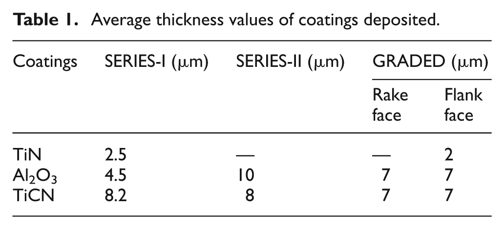
Commercially available cutting tool inserts, coated in series and functionally graded, from Iscar, Seco and Sandvik Coromant with ISO specification TCMT 16T308 (restricted contact length groove type) were used for the cutting tests. The commercial carbide and coating grades were IC 9150 (ISO P01-P30-CVD coated carbide) SERIES-I; TP 1500 (ISO P10-20-CVD coated carbide) SERIES–II; and GC 4215 (ISO P15-CVD coated carbide) GRADED. Iscar inserts (SERIES-I) were multilayer, with coatings deposited in a series as TiCN/Al2O3/TiN, as shown in Figure 1(a). SECO inserts (SERIES-II) were also multilayer with two layers deposited in a series as TiCN/Al2O3, as shown in Figure 1(b). Sandvik Coromant inserts (GRADED) were functionally graded multilayer coated with TiCN/Al2O3 on the rake face, as shown in Figure 1(c-i), and TiCN/Al2O3/TiN on the flank face, as shown in Figure 1(c-ii). In this research, these inserts are referred to as SERIES-I, SERIES-II and GRADED for Iscar, Seco and Sandvik Coromant, respectively. A right-hand tool holder, having an ISO specification of STGCR 2020K-16, was used. Thickness values of the deposited coatings were measured using the scanning electron microscope (SEM). Table 1 shows the average thickness values of the coatings on the cutting tool inserts.
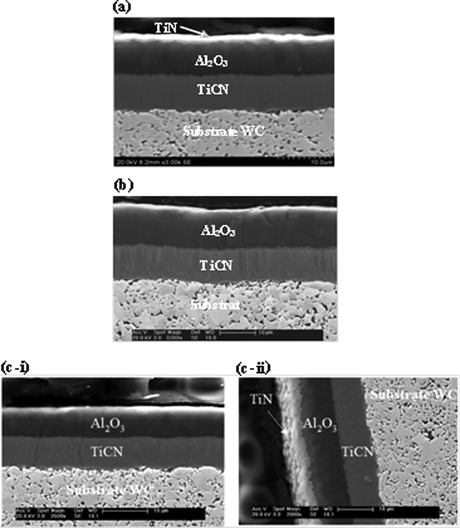
Scanning electron microscope images of multilayer coated inserts (a) SERIES-I (TiCN/Al2O3/TiN) (b) SERIES-II (TiCN/Al2O3) (c-i) GRADED (TiCN/Al2O3) rake face, and(c-ii) GRADED (TiCN/Al2O3/TiN) flank face.
Average thickness values of coatings deposited.
Cutting tests
Commercially available coated tools were evaluated by conducting dry (without coolant) turning tests over a range of cutting velocities between 200 m/min and 879 m/min. AISI/SAE 4140 (a low-carbon high-tensile alloy steel) was used as the workpiece material. The first set of cutting tests conducted was nearly orthogonal (with 91° approach angle) on a semi-automated Dean Smith and Grace Lathe machine. This lathe was selected for accessibility of the working area, which enabled the mounting of the thermal imagining camera and the tool post dynamometer. A tube of 2 mm thickness with an external diameter of 200 mm was prepared prior to the cutting test. Seven different cutting velocities; 314 m/min, 395 m/min, 446 m/min, 565 m/min, 628 m/min, 785 m/min and 879 m/min, were used. A short cutting length of 8 mm was maintained for each cutting speed in order to reduce tool wear. The feed rate and width of cut were kept constant at 0.16 mm/rev and 2 mm, respectively. Due to the constraint of discrete spindle revolution per minute (on the conventional lathe), the cutting velocities were set on the basis of available spindle velocities. Cutting forces were measured using a Kistler three-component piezoelectric dynamometer type 9263 and a data acquisition software system was used on a PC to record the amplified signals.
The second set of cutting tests was conducted on a MHP computer numerically controlled (CNC) turning centre MT-50 for the investigation of maximum flank wear over a longer cutting time. The CNC machine enables the control and standardisation of the interval between passes and represents common practice in industry. A workpiece of diameter 150 mm was prepared by removing 3 mm from the outer skin to eliminate surface inhomogeneties. External turning was performed at cutting velocities of 200 m/min, 314 m/min, 565 m/min and 879 m/min. For each cutting speed, cutting lengths were set between 80 mm and 240 mm. The feed rate and depth of cut were kept constant at 0.16 mm/rev and 1 mm, respectively.
Temperature measurement
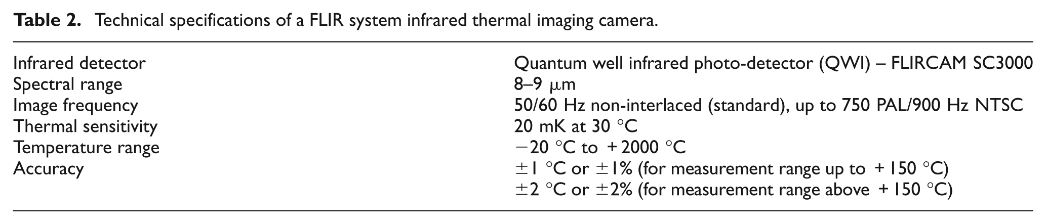
Temperatures were measured during the first set of cutting tests (i.e. on a semi-automated lathe) on the rake face of the cutting tool insert. This was conducted using a thermal imager, FLIR CAM SC3000, with a ThermaCAM Researcher package. Details of the camera are given in Table 2. The main advantage of using an infrared (IR) thermometry is its ability to measure temperatures without any contact of the sensor with the tool and with reduced thermal inertia. 28 Other advantages include its effective application on a small target size and its high spatial resolution, 13 and excellent performance with highly dynamic objects and events. 29 The camera was mounted in such a way that the rake face of the cutting tool was prominently visible. Temperature measurement locations were selected on either side of the chip flow zone (i.e. Path-1 and Path-2 as shown in Figure 2), to avoid any obstruction due to the chip flow. Temperature measurements were repeated and the mean value on each path was recorded.
Technical specifications of a FLIR system infrared thermal imaging camera.
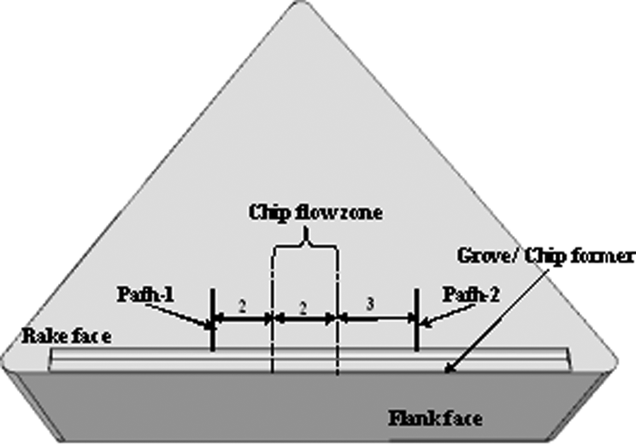
Temperature measurement locations on the rake face of cutting tool insert (all dimensions are in millimetres).
An important aspect that needs to be considered for accurate IR thermometry is the emissivity value of the material/surface. For this purpose, emissivity values of the coated tools at different temperature levels were determined. Cutting tool insert samples were heated between temperatures 100 °C and 1000 °C. Thermal maps were recorded using a thermal imaging camera and the emissivity values were estimated by adjusting values, in the ThermaCAM Researcher software, with both thermocouple and pyrometer readings. A data set of twenty values was acquired and the average of these emissivity values (in the range 0.2–0.3 and 0.40–0.65 for TiN and Al2O3, respectively) was used for the camera calibration of the cutting test.
FE transient heat transfer analysis
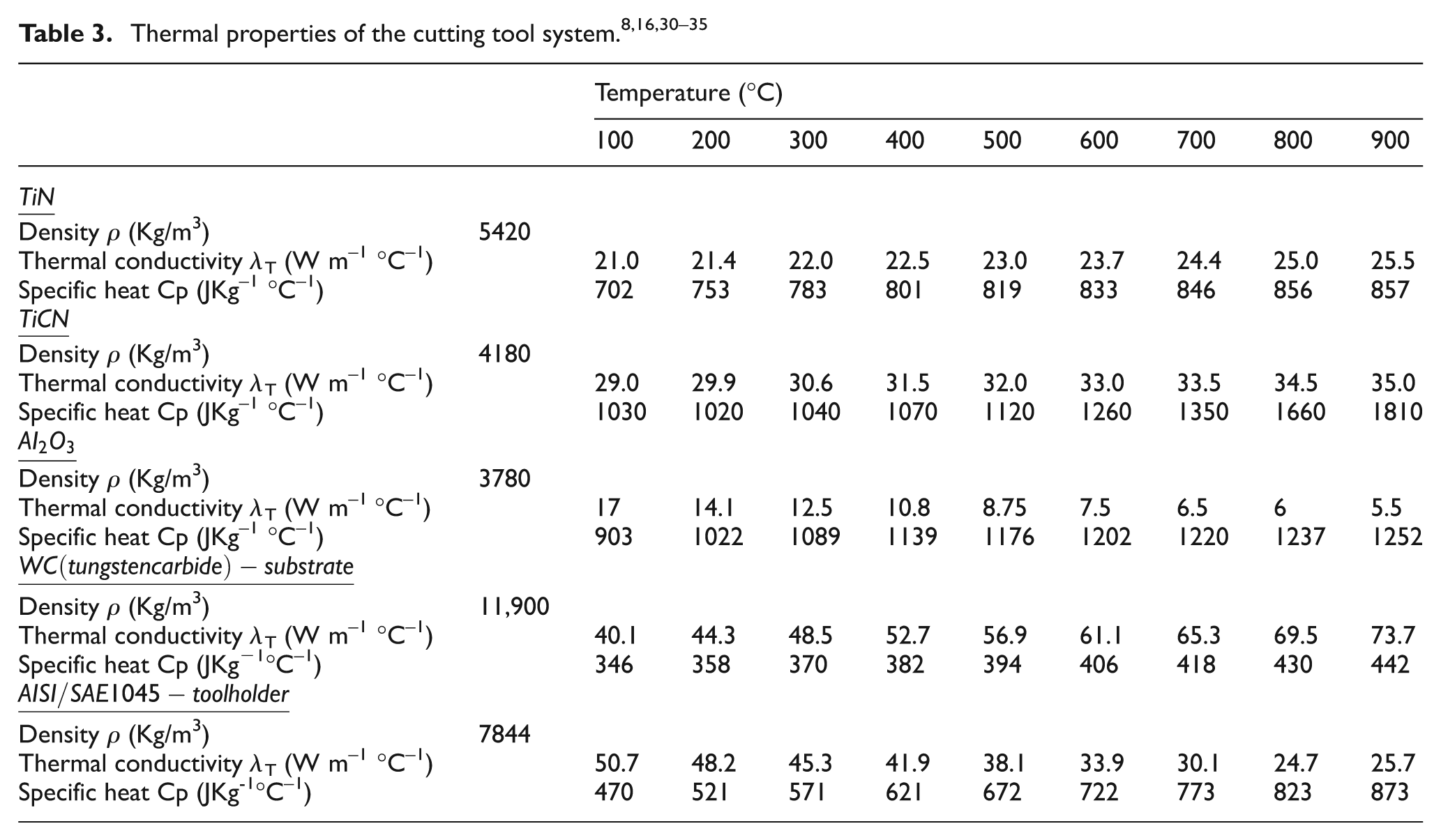
FE transient heat transfer analysis was conducted to predict heat distribution into the cutting tool. Cutting tool assembly, including multilayer coated inserts, shim seat and a cutting tool holder, were modelled in a computer-aided design (CAD) package and imported to the FE commercial code Abaqus/Standard 6.10-1. Chip breaker and restricted contact profiles were modelled only at one edge and minute details were neglected due to the limitation of the FE package. A gradual meshing technique was adopted with increasing element size from the tool–chip contact area (with refined elements) towards non-interaction (non-chip contact) surfaces. A meshed FE model is shown in Figure 3. Temperature-dependent thermal properties were assigned to each part of the coating tool system (i.e. coatings, shim seat and cutting tool holder), given in Table 3. A four-noded tetrahedral heat transfer element DC3D4 was used for the whole assembly of the coated tool system.
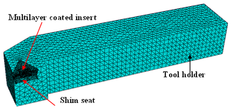
Finite element meshed model of a cutting tool system.
Thermal properties of the cutting tool system.8,16,30–35
Boundary conditions and the assumptions for FE transient thermal analysis are: initial temperature and the far end surface of the tool holder were set at room temperature (25 °C on the day). Convective heat transfer for the entire zone, except for the tool–chip contact area, was specified as h = 20 W m–2 °C. 8 All the parts of the cutting tool system, i.e. coated insert, the shim seat and the tool holder, were assumed to be in perfect contact. A uniform heat flux was considered in the width of the cut direction.
Several researchers23,36,37 have argued that the shear stresses, as given by equation 1 below, along the contact length are not uniform over the entire contact region, but distributed uniformly in the sticking zone and decrease linearly in the sliding zone to zero at a point where the chip leaves the contact zone. Wright et al., 23 Tay et al., 17 and more recently, Fahad et al. 7 and Akbar et al., 5 have treated the shear stress distribution in the contact length as uniform in the sticking region and non-uniform in the sliding regions. This is the approach used in this work. The shear stress (τsh) in the sticking contact zone is given by

where ap and lst are the depth of cut and sticking contact length, respectively, and Ffr is the frictional force on the rake face. Thermal loads (qst) applied on the tool–chip contact length were calculated using the experimental data from equation (2)

where Vch is the chip velocity. Details for the estimation of heat source on the rake face with restricted contact length with groove profile can be found in Fahad et al. 11
Methodology for the prediction of heat partition into the cutting tool
Figure 4 shows the detailed methodology for the prediction of heat partition (RT) into the cutting tool insert using FE transient thermal analysis. Initially 100% heat flux calculated from the experimental test data, as discussed earlier, was applied on the tool–chip contact area (uniform or non-uniform, as appropriate) for the same duration as the machining time. This heat flux was then reduced until the temperature values on each path (Path-1, Path-2, as shown in Figure 2) were matched with the experimentally measured temperatures on the rake face. The percentage of heat flux at which the FE temperatures were matched with the experimentally measured temperatures, was considered as the percentage of the heat entering the cutting tool. This methodology was successfully adopted previously by several researchers to evaluate average heat partition on the secondary deformation zone.7,13,14,38–40
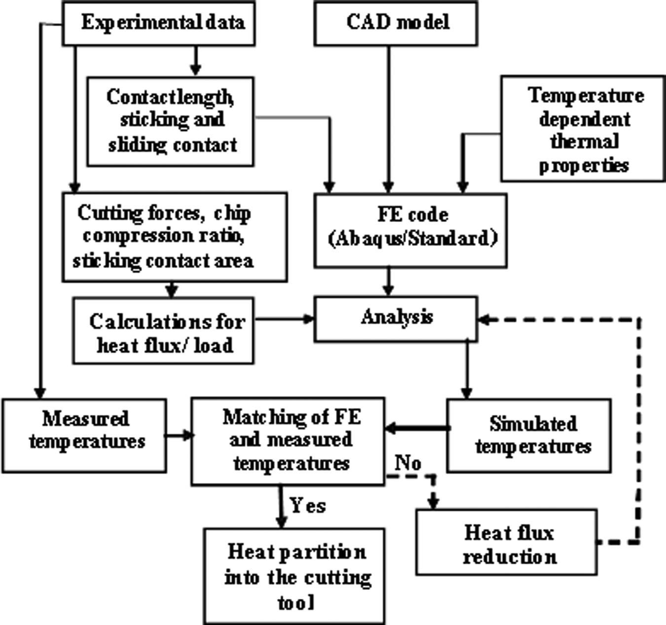
Methodology for the prediction of heat partition.
Results and discussion
Cutting forces
Figure 5 shows the variation of cutting forces with the cutting velocity. It can be seen that, as the cutting velocity increases, cutting forces decrease for all three cutting tool inserts. This reduction is due to the softening of material at elevated temperatures that results in easier deformation. 41 Furthermore, there is no significant difference in the cutting forces or feed forces for all the three inserts. The reduction in the cutting forces from cutting velocities of 314 to 879 m/min is 13.5%, 11% and 12% for SERIES-I, SERIES-II and GRADED, respectively. Percentage reduction in the feed force from cutting velocities of 314 to 879 m/min is 14, 19 and 23 for SERIES-I, SERIES-II and GRADED, respectively. The significant reduction from 314 m/min to 879 m/min cutting velocity in the feed force for both SERIES-II and GRADED tools is owing to the presence of the Al2O3 top layer on the rake face, which reduces the coefficient of friction at elevated temperatures.
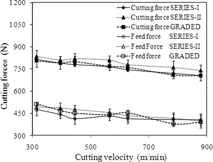
Variation of cutting forces with cutting velocity for SERIES-I, SERIES-II and GRADED tools.
Chip compression ratio and shear angle
The chip compression ratio is the ratio of deformed to the un-deformed chip thickness value. This ratio indicates the efficiency of the chip formation and approximates the degree of deformation of the chip. 11 Figure 6 shows the chip compression ratio for the three cutting inserts. The decrease in the chip compression ratio can be attributed to the formation of thinner chips as the cutting velocity increases, resulting in a decrease in the chip load and hence lower cutting forces. It can be noted that there is a significant reduction in the chip compression ratio in the case of the SERIES-I insert which is 18% from 314–879 m/min. In the case of the SERIES-II and GRADED inserts, it is 12.10% and 11.5%, respectively. On the other hand, the shear angle increases with an increase in the cutting velocity, as shown in Figure 7. A larger shear angle is favourable for a good surface finish with relatively low cutting forces, 42 but this increase in shear angle reduces the area of the shear plane, which may produce higher thermal loads in a narrow zone near the cutting edge. This can have detrimental effects at higher cutting velocities and can lead to early chipping of the cutting edge.
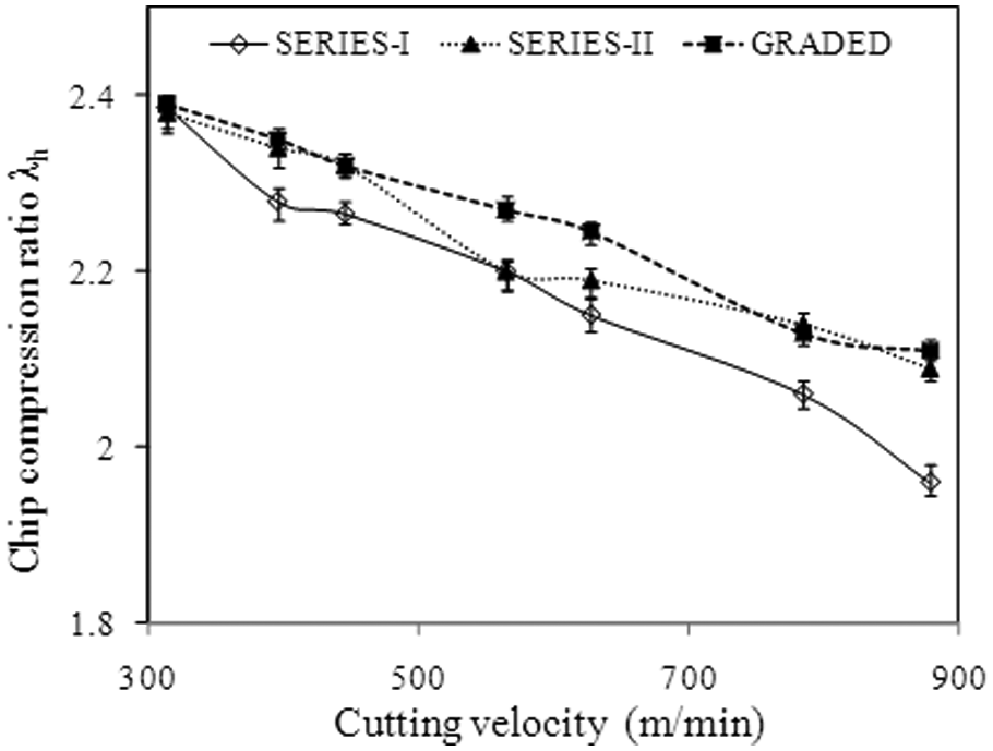
Variation of chip compression ratio with the cutting velocity.
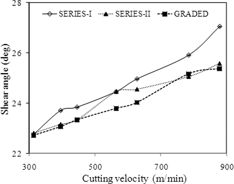
Variation of shear angle with the cutting velocity.
Tool–chip contact area, sticking and sliding
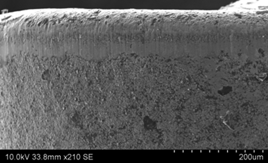
The tool–chip contact area is an input parameter required for FE analysis for the prediction of heat partition. It controls the dissipation of heat into the cutting tool, chip and the workpiece. A larger contact area increases the heat distribution into the cutting tool and vice versa. 43 In the current study, the tool–chip contact area is measured using a SEM, a sample SEM image is shown in Figure 8. The methodology for measuring the tool–chip contact area of inserts with restricted contact length groove type inserts is different from the flat rake face inserts. A sample 2D cross-sectional SEM image and the rake face geometry, as shown in Figure 9 is used to identify the primary and secondary rake faces of inserts. Details of this methodology can be found in previous studies.11,44Figure 10 shows the variation of the tool–chip contact area with the cutting velocity. It can be noted that, as the cutting velocity increases from 314 m/min, the contact area decreases. This phenomenon of decreasing contact length with the increase in cutting speed is well known 45 and an important advantage of HSM. A SERIES-I insert has the lowest tool–chip contact area in the entire range of cutting velocity (i.e. 314–879 m/min). This is owing to the TiN (coated as top layer) having a lower coefficient of friction at lower velocities, as compared with Al2O3 (coated as a top layer on SERIES-II and GRADED inserts). However, it can also be noted that as the cutting velocity increases, the difference between the contact areas for the three inserts is not significant. This is due to the excellent tribological properties of Al2O3 at higher temperatures. 8

SEM image of the contact area of SERIES II inserts at a cutting speed of 879 m/min.
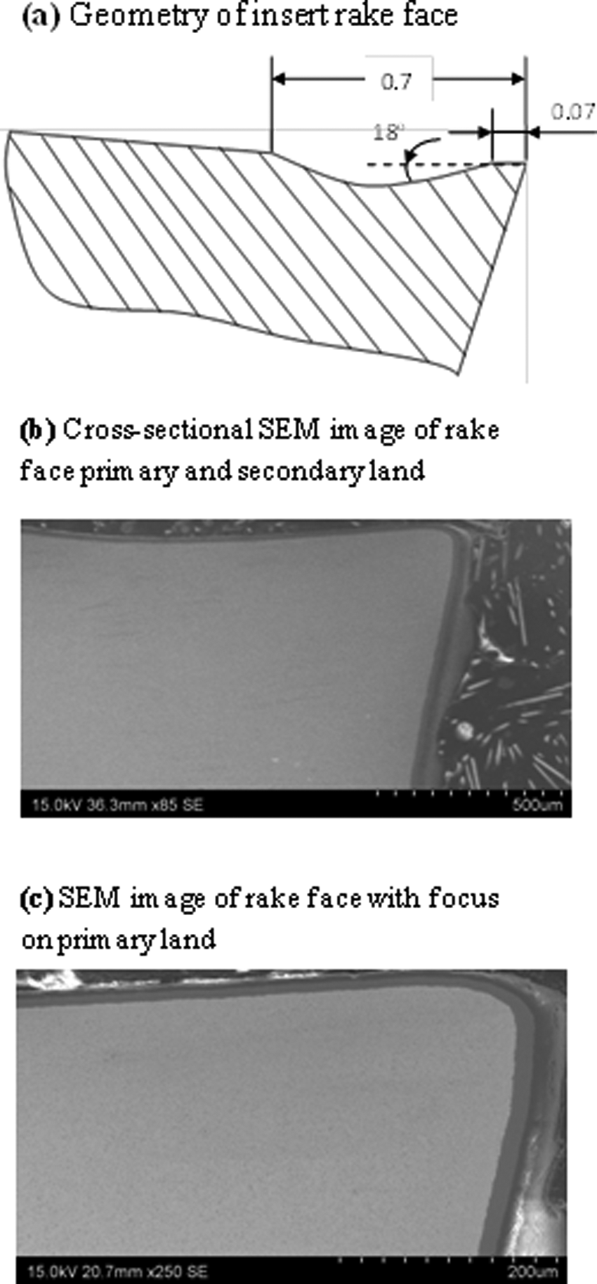
Geometry and SEM cross-sectional views of insert rake face.
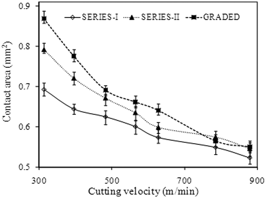
Variation of tool–chip contact area with the cutting velocity.
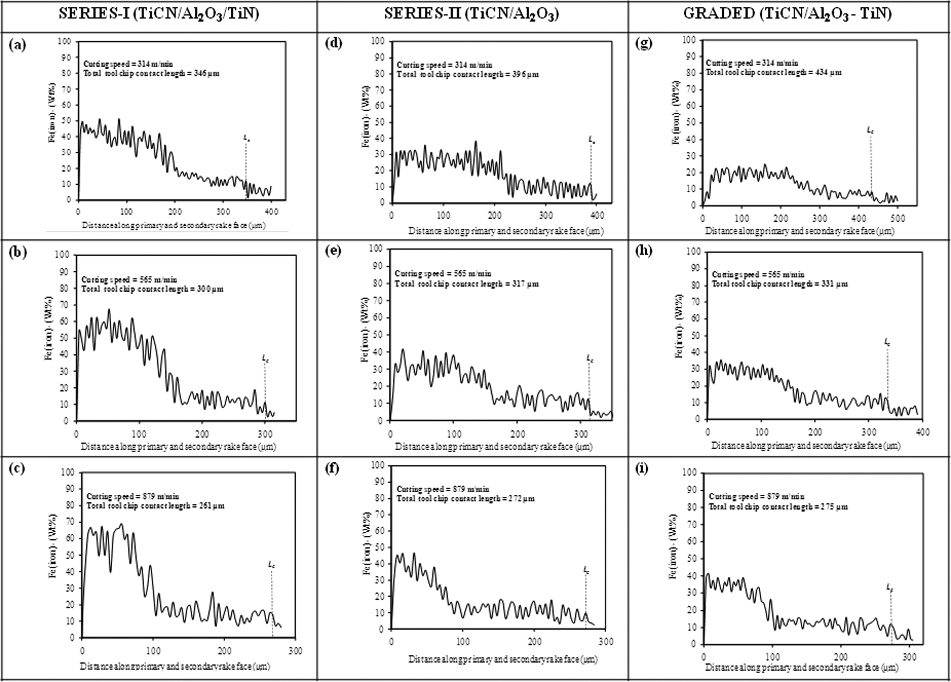
Further investigation was carried out within the contact length to distinguish between sticking and sliding zones. SEM-energy-dispersive X-ray analysis (EDXA) was conducted to evaluate the percentage of Fe (iron) concentration on the tool–chip contact length. This methodology of distinguishing sticking and sliding regions within the contact length has previously been used by several researchers.7,13,46Figure 11 shows the percentage of iron concentration along the tool–chip contact length for SERIES-I (Figure 11(a), (b) and (c)), SERIES-II (Figure 11(d), (e) and (f)) and GRADED (Figure 11(g), (h) and (i)) inserts at cutting velocities of 314, 565 and 879 m/min. It can be noted that average iron concentration in the case of SERIES-I inserts is higher for all cutting speeds. At the lower cutting speed of 314 m/min, a high iron concentration (average of 35%) up to 207 µm from the cutting edge supports the presence of material transfer on the rake face of cutting insert, as shown in Figure 11(a). The sudden drop beyond this point shows the reduction in iron transfer, which remains at an average of 14% up to 346 µm from the cutting edge. Therefore, it can be reasonably assumed that at the cutting speed 314 m/min, the percentage of sticking and sliding is approximately 60 and 40, respectively. For SERIES-II, a lower material transfer is observed in Figure 11(d) at the cutting speed of 314 m/min as compared to SERIES-I. The average iron concentration up to 217 µm is 25%, which reduces to an average of 12%. It can be deduced that the contact length can be divided into 55% sticking and 45% sliding. Figure 11(g) shows the material transfer on the GRADED insert, which is 20% (average) up to 233 µm from the cutting edge and reduces to 10% (average). This material transfer supports the sticking and sliding regions of 54% and 46%, respectively.
SEM-EDXA results of Fe (iron) concentration along the tool–chip contact lengths.
At the cutting speed of 565 m/min, the average iron concentration up to 152 µm from the cutting edge is above 40% for SERIES-I, as shown in Figure 11(b). At this cutting speed the percentage of sticking and sliding is 51 and 49, respectively. In the case of SERIES-II, (Figure 11(e)) the iron concentration analysis shows sticking and sliding as 48% and 52%, respectively. And for a GRADED insert (Figure 11(h)) at 565 m/min sticking and sliding is 45% and 55%.
At 879 m/min for SERIES-I (Figure 11(c)), the sticking zone is reduced to 92 µm from the cutting edge and the sticking and sliding are 35% and 65%, respectively. For SERIES-II inserts, the percentage of sticking and sliding can be deduced as 29 and 71, respectively, and for GRADED inserts sticking contact is reduced to 25% of the total contact length at 879 m/min.
It is observed that for the entire range of cutting speeds, the total contact length is lower for a SERIES-I insert (Figure 11), but the sticking part of the contact length, and also the average iron concentration, is higher than compared with SERIES-II and GRADED inserts. According to Ezugwu and Okeke, 47 thermal effects caused by coating materials can influence the behaviour of the tribo-contact between the cutting tool and the chip. The lower iron concentration on the inserts with Al2O3 as a top coat (in SERIES-II and GRADED) and also smaller sticking contact length can be attributed to the self lubrication property of Al2O3 at elevated temperatures, 48 which results in lower material transfer on the inserts.
Tool wear
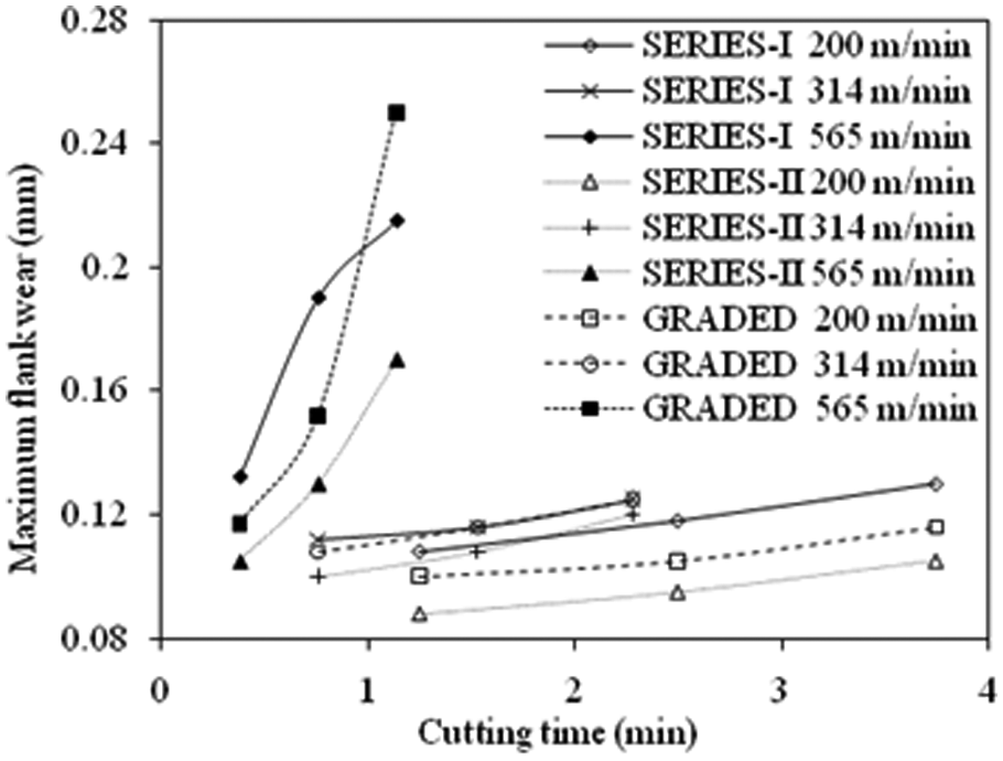
Figure 12 shows the variation of maximum flank wear with the cutting time at cutting velocities of 200, 314 and 565 m/min. SEM images (a sample image is shown in Figure 13) of worn multilayer coated tools (for SERIES-I, SERIES-II and GRADED) were examined and the maximum flank wear was measured in accordance with ANSI/ASME B94.55M-1985(1995). 49 At the cutting velocity of 200 m/min, the flank wear progression is slow for all three inserts. It can be seen that at this cutting velocity the SERIES-II insert shows the lowest flank wear followed by the GRADED insert, which is only slightly higher. The SERIES-I insert shows the highest flank wear at this cutting velocity. At 314 m/min, there is no difference between the flank wear of SERIES-I and GRADED inserts, but the SERIES-II insert shows lower flank wear compared with the other two inserts. At 565 m/min flank wear for SERIES-I and GRADED progresses rapidly while for SERIES-II this progression is slow. Better wear resistance of the SERIES-II insert can be attributed to the thicker layers of coatings (18 µm – cumulative), compared with SERIES-I and GRADED (15.2 µm and 16 µm, respectively). According to Ezugwu and Okeke 47 , tools with multiple thick coated layers offer greater stability and mechanical support to the cutting edge and are expected to perform better at higher cutting velocities.
Variation of maximum flank wear with cutting time.
SEM image of flank wear of SERIES-I insert at cutting speed of 314 m/min.
All three inserts were repeatedly tested at the cutting speed of 879 m/min, but with the occurrence of rapid chipping no further tests were conducted at this speed. Wear tests show that in the entire range of cutting speed, except at 879 m/min, SERIES-II performed best among all three inserts. GRADED inserts performed better than SERIES-I at 200 m/min and also for short machining time at cutting speed of 565 m/min.
Heat partition into the cutting tool
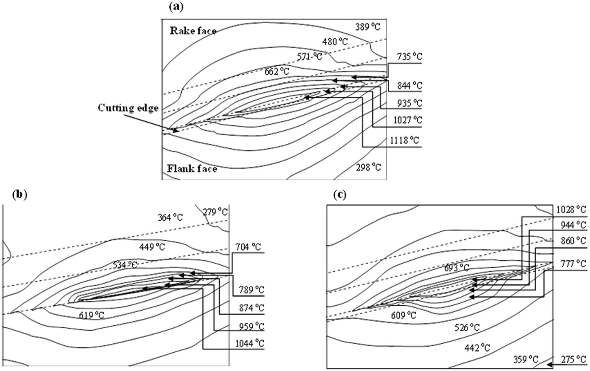
FE transient heat transfer analysis results in Figure 14 show the temperature distribution for multilayer coated tool inserts (SERIES-I, SERIES-II and GRADED) at the cutting speed of 565 m/min. Temperature contours for all the three inserts show high temperatures at the tool–chip contact area, as expected.
Temperature distribution results of FE simulation at cutting speed 565 m/min for (a) SERIES-I, (b) SERIES-II, and (c) GRADED inserts.
Evaluation of heat partition was conducted by matching FE temperatures on preselected paths (Figure 2) with the experimental results. Figure 15 shows final simulated and measured temperatures and the corresponding percentage difference at cutting velocities of 314 and 879 m/min for the three inserts. A good agreement is observed between FE and experimental results with a difference of not more than ±6%. There is an increase in temperature values as the cutting speed increases in the case of SERIES-I. In the case of SERIES-II and GRADED inserts there is a reduction in temperature on the preselected paths. The increase in temperature with the cutting speed on both paths in case of SERIES-I (with TiN as the top coat) is due to the thermal conductivity of TiN, which increases with temperature. Therefore, heat is distributed widely on the rake face as well as on the flank side. In the case of SERIES-II, the top coat is Al2O3, which has a unique trend of thermal conductivity decreasing, with an increase in temperature. This restricts the expansion of heat on the rake face and leads to a temperature reduction, 11 as shown here on the preselected paths. In the case of the GRADED insert, the Al2O3 coat on the rake face restrains the heat expansion on the rake face, but owing to the presence of TiN on the flank side, higher temperature gradients are on the flank side Figure 14(c).
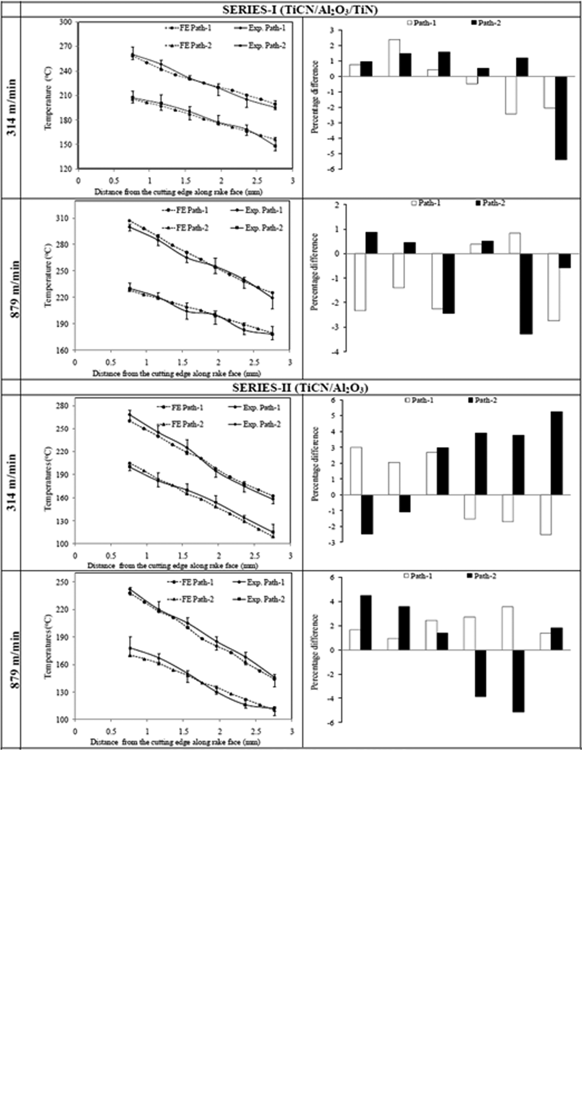
(continued)
Heat partition (RT) into the cutting tool was predicted using the methodology discussed earlier in ‘FE transient heat transfer analysis’. Figure 16 shows heat partition into the cutting tool inserts for SERIES-I, SERIES-II and GRADED inserts at cutting velocities in the range of 314 m/min and 879 m/min. It can be noted that heat fraction flowing into the cutting tool inserts decreases as the cutting speed increases. This is owing to the reduction in contact length as the cutting speed increases, i.e. a smaller contact length results in less heat distribution into the cutting tool. 14 Additionally, a reduction in the thermal conductivity of the Al2O3 coating for higher cutting velocities promotes a lower heat partition into the cutting tool. The reduction in heat partition into the cutting tool from cutting speed 314 m/min to 879 m/min for SERIES-I, SERIES-II and GRADED is 61%, 68% and 63%, respectively. It can be noted from Figure 16 that the SERIES-I insert shows the highest heat distribution into the cutting tool inserts. Although, the contact length for the SERIES-I insert is smaller (Figure 9), the sticking contact length is larger (Figure 11) as compared with the other two inserts (i.e. SERIES-II and GRADED). This can be attributed to the uniform shear stress on a larger area (sticking contact area) and hence more heat into the cutting tool.
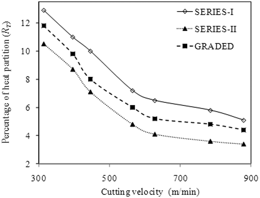
Variation of heat partition into the cutting tools with cutting velocities.
Although the parameters discussed earlier, i.e. tool–chip contact, sticking and sliding contact regions for SERIES-II and GRADED inserts, are comparable, especially at higher velocities, the heat partition is lower for the SERIES-II insert for all cutting velocities. This could be owing to the 10 µm thicker layer of Al2O3 or a cumulative thickness (18 µm) of multilayers (TiCN/Al2O3) in SERIES-II inserts compared with a 7 µm Al2O3 layer or cumulative thickness of 14 µm (TiCN/Al2O3 on rake face) in GRADED inserts.
All three inserts have a Al2O3 coating, an intermediate layer in the case of SERIES-I and a top layer in the case of SERIES-II and GRADED inserts. This layer acts as a thermal barrier. Also, as seen in Figure 17, the equivalent thermal conductivity of the SERIES-II coating system is the lowest. This may be another reason for limited heat partition into the SERIES-II cutting tool insert. Therefore, it can be deduced that, although the optimal coating thickness and smaller sticking zone near the cutting edge is favourable, nevertheless, localised shear stresses in a narrow zone near the cutting edge leads to severe chipping of the insert edge or rapid tool wear.
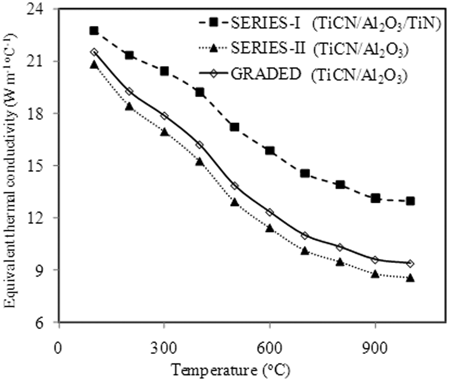
Variation of equivalent thermal conductivity with temperature.
Conclusions
In this study, multilayer coated tungsten carbide cutting tool inserts were evaluated. This was conducted through experimental studies that included generation of data for cutting forces, chip compression ratio, tool–chip contact phenomena and flank wear. Furthermore, heat partition into the cutting tool was estimated using experimental data as input to FEM analysis. Material transfer to the rake face of the cutting tool insert was evaluated using SEM-EDXA area scans. This allowed the definition of sticking and sliding regions on the rake face to enable the setting of appropriate heat flux schemes.
Inserts coated with a TiN coating as the top layer (SERIES-I) shows a smaller contact length. However, owing to a larger sticking contact and higher concentration of workpiece material transfer, the amount of heat load into the insert was higher and may lead to a shorter tool life. On the contrary, the presence of Al2O3 as a top layer on the rake face shows a higher contact length but smaller sticking contact and lower workpiece material transfer. This implies that the selection of top coating for a cutting tool insert is crucial for efficient HSM.
Although all three inserts were multilayer coated systems, TiCN/Al2O3 (SERIES-II) gives the lowest heat partition and the best wear performance against SERIES-I (TiCN/Al2O3/TiN) and functionally graded GRADED ((TiCN/Al2O3/TiN)flank (TiCN/Al2O3)rake) inserts. This shows that, in addition to the selection of top coating, optimum coating (layer) thickness and equivalent thermal conductivity of the coating system is also important in reducing heat partition and tool wear.
Footnotes
This research received no specific grant from any funding agency in the public, commercial, or not-for-profit sectors.