
Abstract
Although a great variety of cutting dynamometer designs are available, the research laboratories/industrial users still find them difficult to employ in real production environments; this is mainly owing to the difficulty in changing tools/cutting edges in an automated manner. To address this, a new design concept for innovative dynamometers for cutting operations (for example, turning), which can allow flexible/automated tool change without any disturbance to the industrial setups, i.e. tooling magazine, is presented in this article. The design of the dynamometers relies on an embedment of a 3-axis load cell into a tool holder on which automated tool change can be performed easily. Taking into consideration the working environment, fine-tuning of the design of the dynamometers was performed to enable the use of through-tool high coolant supply. Then, by use of uncertainty budgeting related to the assembly and calibration of the dynamometers, the measurement errors originating from the design concept have been reduced to 5%. By performing turning experiments, the proposed dynamometer concepts have been evaluated in terms of maximum loads that can be taken without losing their stability. This enabled evaluation of the drawbacks of a particular concept for which a good design solution has been proposed and tested at high values of cutting parameters.
Introduction
The measurement of the forces involved in machining is critical to understanding the conditions under which the machine, tool and workpiece perform; factors including power consumption, tool wear and surface quality are significant. Of particular importance is the determination of cutting forces. 1 In addition, the identification of optimal part clamping/fixturing solutions is key when machining low rigidity components; 2 in these situations the level of cutting forces directly influence the geometrical accuracy of machined parts. Moreover, over the past years significant effort has been put into developing monitoring solutions 3 to enable machining with minimal malfunctions (e.g. faulty tools,4,5 chatter,6,7 surface anomalies8,9). From the published literature it seems that a significant number of approaches use cutting force measurement systems, sometimes in association with other sensory systems.10,11
The majority of cutting force measuring applications are based on two constructive solutions:
evaluation of elastic deformation of mechanical elements, where strain gauge systems are used; 12
utilising the piezoelectric effect of quartz crystals (e.g. SiO2), which outputs a charge proportional to the applied forces. 13
The use of strain gauges might involve appropriate design solutions to proof the system against (high pressure) cutting fluids; hence, this measuring approach might not be the first option. On the other hand, the dynamometers that use piezoelectric cells tend to be bulky and have limited versatility as, most of the time, they require preloading.
Despite the need for cutting force-measurement systems and the various constructive solutions, 14 it seems that very few off-the-shelf dynamometers made their way into real production environments. This is owing to their current construction that only fit particular applications (e.g. milling/drilling, turning) and, more importantly, owing to the limitation of not allowing automatic tool change to support multi-task machining that is current industrial practice. If such a facility were developed, then the tendency of monitoring cutting forces at the tool rather than at the workpiece (using bulky platform dynamometers with low versatility) will increase. This offers the benefit of easily supervising multi-task cutting operations while allowing all the functions (e.g. through-tool coolant supply) of the machine to work at full capacity.
The aim of the work was to develop a dynamometer more suited for research and industry environments where machining setups need to be changed frequently. Thus, this article discusses:
design of a novel cutting force measurement system (used in this case for turning) capable of working in a multi-task machining environment while allowing versatility of cooling application (e.g. through tool ultra-high pressure);
development of an uncertainty model related to assembly and calibration of the dynamometer to enable minimisation of measurement errors;
assessment of design and suitability when employed in real production environments; this involved the assessment of cutting forces/setup robustness.
Targeted capabilities versus design specifications of a versatile force-measuring system
In this approach, the dynamometer needs to satisfy the following functions.
Ability to be embedded into a truly versatile tool holding system that can be used for both static (e.g. turning) and rotary (e.g. milling) tools; this lead to the use of a Coromant-Capto® holding system within which the multi-component force-measuring system can be embedded. This is an essential feature for dynamometers that are to be used in real industrial environments.
Allow automated/rapid tool change that enables its utilisation in multi-task machining. This was addressed by placing the force measurement system between the machine end-effector (e.g. spindle) and the changeable cutting edges.
Enable full functionality of the machine tool (i.e. axis movements) and the use of state-of-the-art through-tool cutting fluid (e.g. ultra-high pressure: >200 bar) application. This should be addressed by a compact and water-proof design.
Be easily calibrated and have good measurement repeatability in a wide range of machining conditions. This should be addressed via an innovative design to allow easy calibration (using dead-weights/testing machines) followed by error budgeting, and testing in cutting conditions.
Development of design concept and analysis for the dynamometer
Design concepts
In the following, two iterative design concepts of dynamometers (shown in Figure 1), which use a 3-axis load cell (Kistler 9167A) as a measuring element, are presented.
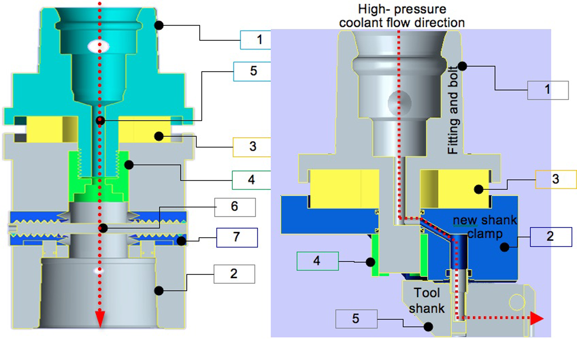
Cross section of the model of innovative dynamometers. (a) Concept 1: initial design; (b) Concept 2: advanced design.
Concept 1
The dynamometer uses a base part (1) provided with a k-shape type profile that allows both accurate tool positioning and cutting force/torque loading and, a modified holding element (2) to enable the insertion of the piezoelectric cell (3); no mechanical contact between the elements (1) and (2) exists so the cutting forces are transmitted only through the piezoelectric cell that is pre-loaded (100 kN) using a hydraulic press while tightening the nut (4). The alignment of the elements (1), (2) and (3) is done by inserting a key into the conjugated slots (5), which is then removed once the pre-loading is finished. The front clamp system (not presented here) that holds the cutting edge is assembled within the Capto female fitting utilising a draw bolt (6) with opposite handed threads (7) at either end.
Concept 2
In this case the design was simplified (by avoiding the standard front clamp) and it was directed towards increasing the compactness of the system. To achieve this, the base part (1) was modified so that the fluid channel is connected to a newly designed shank clamp (2) in between which the load cell (3) was placed. The alignment of these elements is ensured in the same way as above (using key slots) while the pre-loading of the piezoelectric cell is ensured using a hydraulic press and tightening the nut (4). The tool shank (5) is easily attachable to (3) using a Sandvik-Coromant proprietary system.
Concept evaluation: uncertainty modelling of force measurement and calibration
Dealing with new dynamometer designs, a rigorous assessment of the uncertainties associated with their constructive solutions needs to be addressed. Figure 2 shows a possible ‘non-ideal’ setup of the piezoelectric cell (reference system xP, yP, zP) within the mechanical elements of the dynamometer from where the following main positioning errors can be identified in relation to the machine axis, xM, yM, zM (here considered without errors, E).
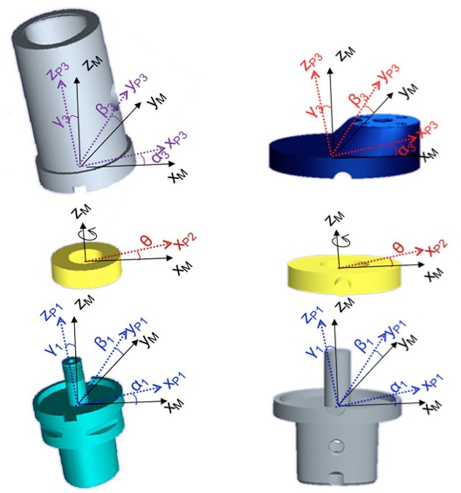
Illustration of a possible ‘non-ideal’ setup of the piezoelectric cell (xP, yP, zP) within the mechanical elements of the dynamometer with reference to the machine axis (xM, yM, zM) for Concept 1 (a) and Concept 2 (b) designs.
E1: As the frontal surface of the base part (1) is not perfectly perpendicular on the machine zM-axis, this will make the piezoelectric cell (that sits on it) to tilt with reference to the same axis (see rotational angles α1, β1, γ1).
E2: The piezoelectric cell can be rotated with angle θ round the z-axis resulting in misalignment of xP and yP axis.
E3: Furthermore, sitting on the piezoelectric cell, the holding element (2) will have its own positioning errors with the xP, yP, zP materialised as additional rotational angles α2, β2, γ2.
In this way, when applying a calibration force
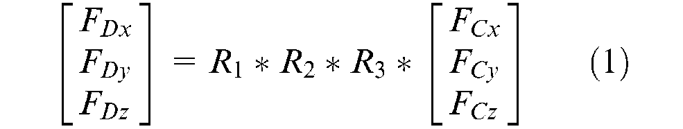
where
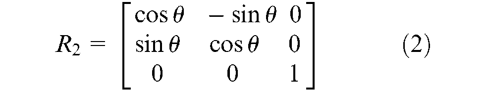
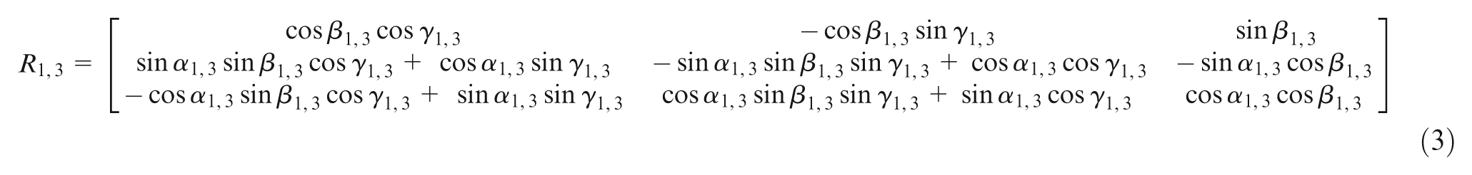
Having expressed the relationship between the measured forces (FD) and the real ones (FC), equation 1, the rules for evaluating uncertainties 15 were followed by considering averaged values of the contributing errors (e.g. non-coaxially of the axis of different elements of the dynamometer) and their variability (i.e. standard uncertainties) as normal distributions, based on which the combined uncertainty of measured forces FD has been evaluated. The error budgeting was carried out with a free-source software (GUM Workbench 16 ) and example results can be observed in Table 1 (for a nominal calibration force FCz of 1000 N); Table 1 contains the input data of equations (2)–(3) that are substituted in equation (1) along with the calibration force (FC) in a particular direction. The summary of the tested results for Fcx,y,z = 1000 N is as follows for 95% confidence intervals: Prototype 1: FDx = 930 ±16 N; FDy = 932 ±19 N; FDz = 949 ±16 N; Prototype 2:FDx = 959 ±12 N; FDy = 971 ±12 N; FDz = 969 ±6 N.
An example of uncertainty budgeting for force readings, FD, for both dynamometer concepts when inputting a nominal calibration force FC of 1000 N along the x, y, z axis.
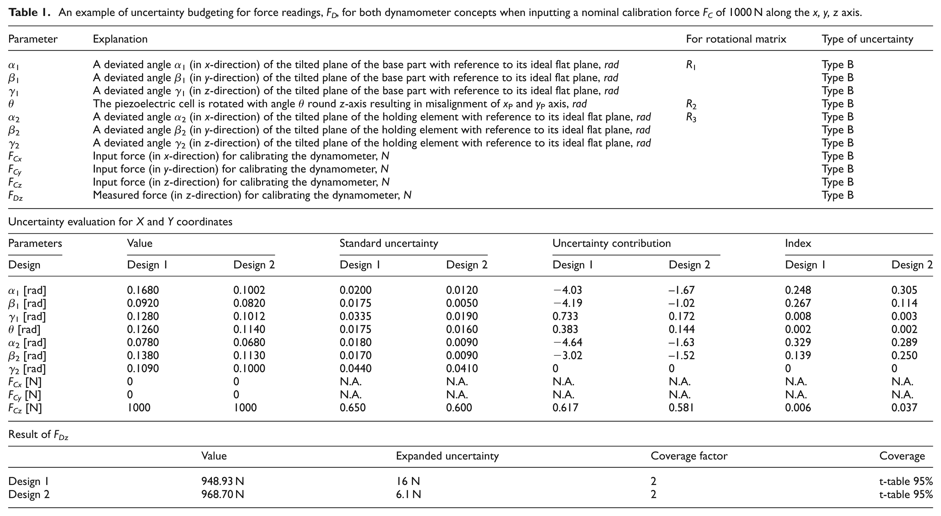
The uncertainty budget (Table 1) revealed that the main contribution on the errors of F
Once the assemblies completed the calibration of the dynamometer by loading along their 3-axis at a maximum 1500 N with 10–100 N equal intervals and the calibration diagrams/equations obtained for each direction of leading (coefficients of correlations 0.95 < R2 < 0.99; upper values for z-axis).
Experimental testing of the dynamometer and further development of the design
With a clear understanding of the uncertainties related to the construction of these dynamometers (Figure 3(a) and (d) turning trials have been carried out to evaluate their robustness in a real cutting environment. For this, an Alpha 1550XR computer numerical control (CNC) lathe was equipped with the two prototyped dynamometers to perform turning tests on 316L using tungsten carbide inserts (Sandvik TNMG 16 04 08-QM) and various parameters: cutting speed v = 220–245 m/min; feed rate f = 0.2–0.4 mm/rev; depth of cut ap = 0.5–3.5 mm; through-tool coolant supply at 70 bar, which was possible owing to the proposed design solutions. The dynamometers were connected to a charge amplifier (Kistler 5017B) and signals were acquired using a peripheral component interconnect (PCI) data acquisition card (NI PCI 6011E) at 10 kHz, digitised and processed using an application in LabView. Figure 3(b) and (c) shows that at less intensive cutting parameters (ap = 1.5 mm, v = 220 m/min, f = 0.2 mm/rev) stable signals are acquired on both dynamometers, while at more demanding parameters (e.g. ap = 2 mm, v = 245 m/min, f = 0.35 mm/rev) it seems that the Prototype 1 dynamometer loses its stability. This was caused by the consequential large bending moments resulting in dynamic instability; hence, the more compact Prototype 2 showed stable outputs even at higher values of cutting parameters (ap = 3.5 mm, v = 245 m/min, f = 0.4 mm/rev). An interesting anomalous phenomenon was observed on Prototype 1 when through-tool high-pressure coolant (>70 bar) was used, a situation in which small negative forces before cutting starts were observed. A close examination of this design indicated that this was because the space between the top of the preload nut and the end of the draw bolt is filled by the high-pressure coolant (Figure 4), this causes reduction of the preloading force on the cell. This anomaly can be easily corrected using the signal acquisition software. Avoiding the ‘front clamping’ solution used by Prototype 1 (Figures 1(a) and 3(a)) and employing three small bolts instead of a draw bolt and clamps to hold the tool shank, the length of Prototype 2 (Figures 1(b) and 3(d)) was reduced to 108 mm leading to reduction of the bending moment by 73.34% and, therefore, resolving the anomaly caused by vibration. Prototype 2 also eliminates the anomaly of initial negative readings generated by high-pressure coolant flow. This is achieved by changing the direction of the internal flow of cutting fluid; as a consequence, the resultant force from the pressure is perpendicular to the preload tension. This removes the force of the pressure from the sensor, allowing only machining forces to be observed.
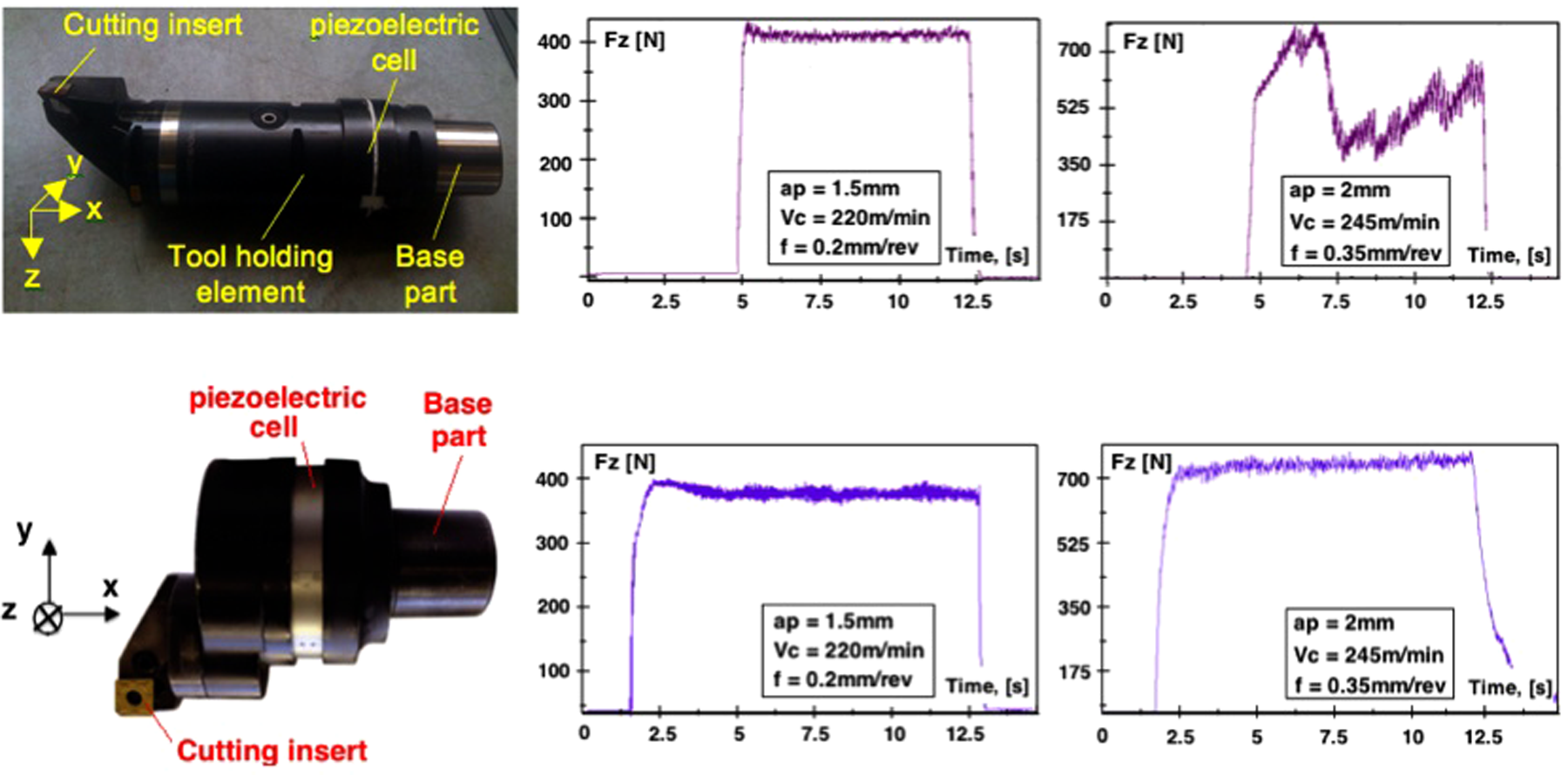
Concept 1 (a) and Concept 2 (d) dynamometers and examples of force (Fz) signals obtained at normal (b) and (e), i.e. ap = 1.5 mm, Vc = 220 m/min, f = 0.2 mm/rev, and (c) and (f) intensive, i.e. ap = 2 mm, Vc = 245 m/min, f = 0.35 mm/rev, cutting conditions.
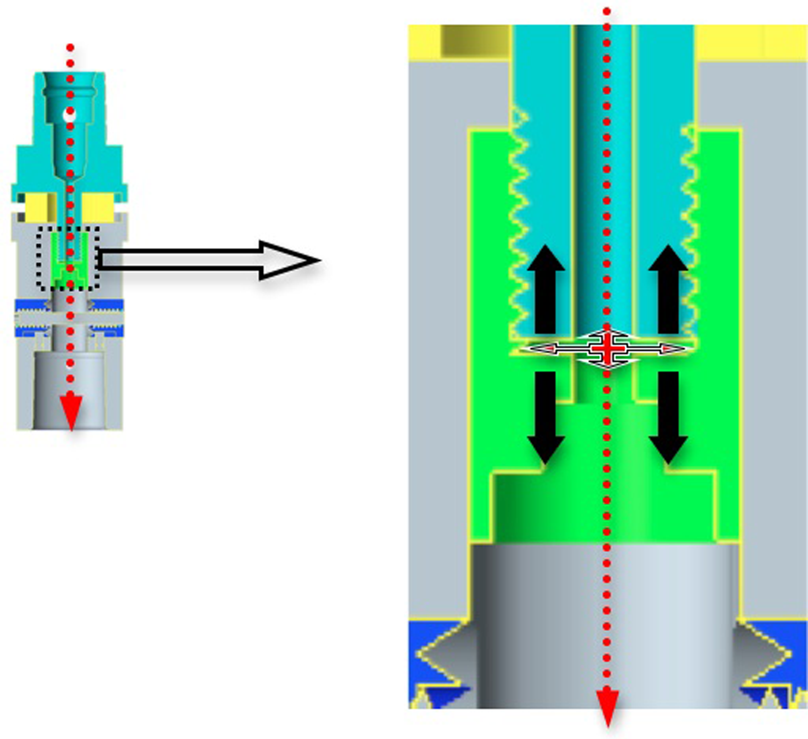
Illustration of high-pressure coolant filling the space between the top of the preload nut and the end of the draw bolt for the design Concept 1.
Conclusions
In response to the need for development of in-process monitoring methods, and based on the extensive knowledge of using cutting forces for supervision of machining operations, development of a design solution for industrially implementable dynamometers has became an important enabler for this technology.
To address this, this article has proposed innovative and real production-applicable designs of multi-axis dynamometers, the following novel aspects of which have been discussed.
The embedment of a 3-axis piezoelectric cell into a modified industrially accepted toolholder so that automated tool change can be performed without disturbing the measurement system or the machine tool working space and facilities (i.e. high-pressure through tool coolant supply). Although exemplified as a turning dynamometer, the proposed design can be transposed to rotational tooling systems.
Budgeting of measurement errors stemming from the construction/assembly of the dynamometer gave an in-depth understanding of the contributions of different system inaccuracies to the output measured force. Apart from the novelty of this approach, the uncertainty budget enabled adjustments of components and assembly procedures of the dynamometer to minimise its measurement errors. This uncertainty budgeting exercise can be regarded as an example for similar approaches in building various force measurement systems.
The experimental trials performed on the first prototype of this novel dynamometer design displayed a good measuring performance within a real industrial environment while highlighting some drawbacks when employing internal high-pressure through coolant and intensive cutting parameters. This enabled the development of an improved dynamometer design that overcame these problems.
Footnotes
This research received no specific grant from any funding agency in the public, commercial, or not-for-profit sectors