
Abstract
We conventionally assume that ceramics are brittle. The risks induced by this structural behaviour do not cancel the undeniable need for ceramics in applications with extreme environmental demands. These constraints could be a high working temperature or wear, where metals cannot be used, or in contact with the human body, where the inherent chemical resistance of ceramics makes them more biocompatible and durable. While the first statement on brittleness still holds true for most ceramics, solutions have been found for some: damage-resistant Ceramic Matrix Composites (CMC) are now part of plane engines, and tough zirconia-based ceramics are routinely used in orthopaedic and dental implants. Because of the intrinsic brittleness of ceramics, the required toughness increase must be introduced by tailoring their microstructure. A lot of ground has been covered since the first descriptions of the toughening mechanisms in ceramics in the 1970s. The goal of this review is thus three-fold: summarise the necessary background in fracture mechanics to discuss complex fracture behaviours, provide a picture of the recent development on all the strategies to toughen ceramics, and finally extract lessons on the efficiency of these various toughening mechanisms. In terms of materials, this review will cover CMCs, zirconia-based ceramics, and bulk ceramics using microstructural engineering, which includes the combination of elongated grains with grain boundary engineering, using carbon allotropes, MAX phases, and bioinspired microstructures. For each we will discuss both the core toughening mechanisms and the most recent studies on it. By gathering all these research strands, we will provide in the final part a reflection on the link between toughness and pseudo-ductile behaviour and how it can help to hopefully reach uncharted territory in terms of structural properties in the future.
Introduction
Structural materials form the framework upon which our societies are built, from housing, biomedical implants, and transportation to energy generation and storage devices. 1 These critical applications require materials that can survive in extreme conditions, e.g., corrosive environments, scorching heat inside jet engines, high wear in braking systems, or radiation in nuclear power plants.2,3 At first glance, metals are the best candidates as they can be made ductile and strong through compositional and microstructural engineering, making them safer to use in safety-critical structural applications. However, most ceramics are intrinsically more resistant to temperature, corrosion, and wear than metals. 4 Ceramics are also generally lighter, making them relevant for transport applications, where their combined high-temperature resistance and low density can lead to better fuel efficiency. 5 Unfortunately, ceramics are brittle for the same reason that they are temperature or corrosion-resistant. The strong iono-covalent bonds at the heart of technical ceramics are hard to break and resist the movement of dislocations, even at high temperatures. Therefore, instead of missing the opportunities provided by ceramics, materials scientists and engineers have been working to find ways to palliate this shortcoming without impacting their intrinsic beneficial properties.
The research on toughening ceramics began from two advancements: from the 1960s with a better description and understanding of fracture mechanics, 6 and later in the late 1970s with the discovery of phase-transformation toughening in zirconia 7 and ceramic matrix composites (CMC). 8 The core idea was to engineer the microstructure and composition to resist crack initiation and propagation by introducing a set of toughening mechanisms that all act to reduce the stress concentration at the crack tip9,10 (Figure 1(a)). In part; this is done through what we will define in this review as microstructural engineering: the manipulation of the shape, morphology, composition and arrangement of the constituents of a material at the micro-level or smaller, including grains, reinforcements (in the form of particles, fibres or platelets) as well as the interfaces between these constituents.
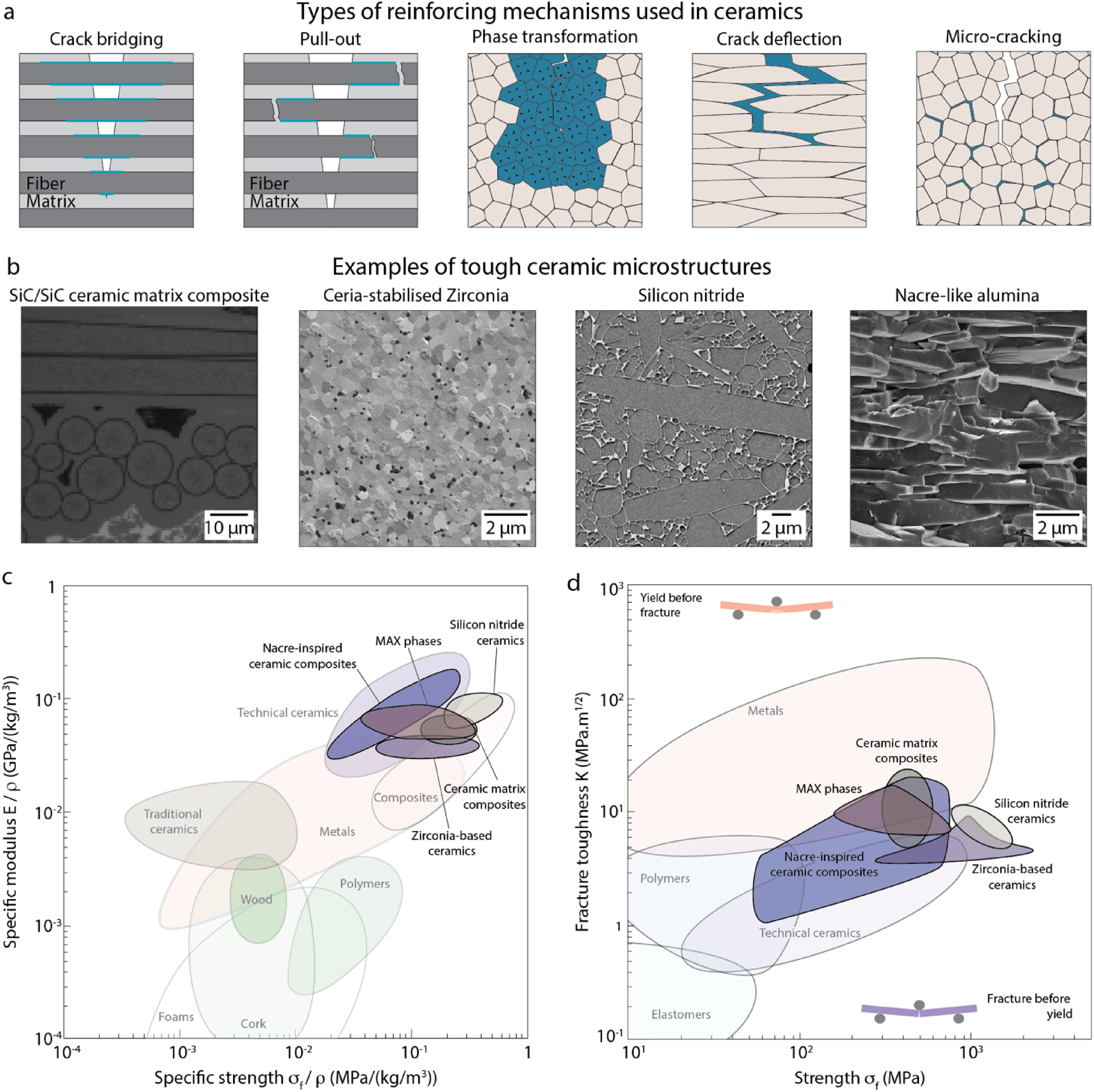
Performance of different tough ceramic families in the structural materials landscape. a. Cartoon of the different toughening mechanisms present in ceramics microstructures, the blue colour is used to highlight the part of the microstructure responsible for the toughness increase. b. Typical microstructure of the tough ceramic families. SiC/SiC CMC microstructure 11 with visible fibre and interface (light grey colour) and matrix (dark grey). Reproduced with permission from Wiley. Zirconia-based ceramic microstructure with visible zirconia grain and impurities (CaO and Al2O3) in dark grey. Reproduced with permission from Elsevier. 12 Polycrystalline Si3N4 polished microstructure with elongated grains and glassy interphase (light grey). Reproduced with permission Elsevier. 13 Nacre-like alumina microstructure with aligned Al2O3 bricks. 14 Reference for data and pictures for CMCs,11,15,16 for zirconia,12,17 for Si3N4,13,18 for MAX phases, 19 for nacre-inspired composites. 14 Ashby maps of c. specific modulus vs specific strength and d. strength vs. toughness. Of the microstructure based on elongated grains, only Si3N4 is represented as it presents the highest properties of this category.
Toughening mechanisms can be of different types, with, for instance, strong anisotropic microstructural elements that will deflect and bridge the crack, introducing pull-out.20,21 Deflection can also be obtained at larger length scales, with cracks deflecting over millimetres at constant angles within laminate structures.22,23 CMCs, for instance, rely on long fibres to introduce crack branching, bridging, deflection and pull-out mechanisms. Stress-induced phase transformation can also hinder crack propagation if the new phase expands in volume. 24 Whereas this has only been observed practically for zirconia-based ceramics, there is still the possibility that other compositions could display phase transformation toughening. Microcracking can also increase toughness in ceramics by reducing the stress intensity factor in the main crack tip through the formation of multiple smaller cracks ahead of it. 25
The introduction of these toughening mechanisms can provide an increase in reliability and safety in use, for instance, because of an increased Weibull modulus and thus more reliable parts’ design or the presence of visible damage before fracture that signals the need for replacement. The two older and more studied materials, zirconia-based ceramics and CMCs, are tough enough that they display a pseudo-ductile behaviour when tested in tension, with irreversible strain on the order of 1%.15,17 As a result, zirconia-based ceramics are routinely employed in hip replacements and dental implants, 26 and CMC in civil plane engines, among other applications. 27
The reliance on the microstructure to stop or hinder crack propagation in ceramics implies fine-tuning at multiple length scales (Figure 1(b)). As a result, new processing techniques are great enablers to study and improve toughening mechanisms. As this review will be focused on the link between microstructure and properties, processing techniques and processing-microstructure relationships will not be covered, but references will be given for the reader to get more information on both these aspects.
Multiple microstructural engineering approaches have been developed over the years to address the main drawbacks of CMCs and zirconia and open new possibilities in the design of tough ceramics. Processing of ceramic matrix composites is complicated, and their strength is relatively low when compared with structural metals. The main drawback of zirconia is the limitation of the transformation toughening mechanism to limited compositions, the restricted temperature window of operation and the risk of ageing. One of these other microstructural engineering approaches is to form microstructures with elongated grains and weak grain boundaries in strong ceramics such as Silicon Carbide, 28 Silicon Nitride,29,30 or Alumina 31 to promote intergranular failure (Figure 1(b)). These elongated grains would act similarly as the fibres in CMC but at a micron length scale, leading to local crack deflection, bridging, and branching.21,32 Other approaches have explored microstructural engineering at even smaller length scales, with the use of nano-reinforcements (defined as particles with one dimension smaller than 100 nm) to improve fracture resistance. Initial work focused on the dispersion of carbide or metallic nanoparticles or whiskers in a ceramic matrix. 33 Following this approach, the rise of exotic carbon allotropes, with mainly carbon nanotubes and graphene, led to their addition in various ceramics to try to reinforce the grain boundaries or promote crack bridging. 34 MAX phases, a family of crystal structures in which a layer of atom with metallic-like bonding is sandwiched between iono-covalent bonded carbide or nitride layers, have been investigated for their possible high toughness. 19 Finally, the study of natural materials with unusual mechanical behaviour has motivated efforts to refine microstructural control in tough ceramics and composites 35 by striving for more precise control of reinforcement orientation, packing, shape, and interfaces. For example, nacre is a part of the structure of seashells that are made of 95% calcium carbonate in volume. Despite this high ceramic volume fraction, nacre exhibits a pseudo-ductile behaviour when tested in tension,36–38 with a yield strength around 70 MPa and a plastic strain reaching 0.7%. This discovery triggered new research that has been reviewed elsewhere, see, for instance.14,39–41 A lot of progress has been made on these bio-inspired materials, with, for instance, nacre-like alumina, a fully ceramic composites based on alumina platelets that reach strength of more than 600 MPa and toughness up to 15 MPa.m1/2. 14 However, none of them shows a behaviour similar to the pseudo-ductile response seen in natural nacre, CMCs, and zirconia when more than 50% of ceramic in volume is used. Other strategies have been used to create ceramics with a pseudo-ductile behaviour or to increase toughness, for instance, due to an increased dislocations density42,43 or shear banding in an amorphous phase, 44 however, up to now, they have only been demonstrated at micron length scale and/or under compression. We will focus this review on those approaches that result in tough ceramics at the macroscale in tension.
By looking at the Ashby map of specific tensile strength and specific moduli (Figure 1(c)), we can directly deduce the interest of the new tough ceramics for transport applications, as they lead to some of the best ratios of strength/stiffness vs density. From the materials maps of strength vs toughness (Figure 1(d)), we can see that the research to improve the toughness of ceramics has paid off: most of the new compositions are stronger and tougher than typical technical ceramics and have reached similar values to those of structural metals.
The authors’ goal for this review is for it to be used (i) to introduce this field to new readers, (ii) to establish the current picture in the field of tough ceramics, and (iii) to provide guidelines to guide the development of the future tough ceramics, to reflect on the relationship between toughness and pseudo-ductile behaviour. Because the development of tough materials is intimately linked to our understanding of fracture mechanics, the advances and limitations we are experiencing will also be provided as a starting point. What makes this research field even more relevant is its impact on a broader context within today's ecological pressing issues: some of the most used and developed energy-related materials, going from electrochemical storage45,46 to mechanical storage, 47 are based on ceramic and their structural properties are key to provide performance jumps in durability as devices failure is often mechanical in origin,48,49 and it is quite evident that ecological pressures will drive durability as a stronger criterion for material choice in the future, putting ceramics in a better position should their reliability be sufficient and their fabrication simple enough.
To answer these three goals, the review is structured in three parts. The first part provides a summary of the necessary concepts in fracture mechanics and the links between fracture toughness and global mechanical properties such as strength, plastic strain, and, to some extent, reliability. The second part provides a summary of the fracture behaviour of three families of tough ceramics currently being researched: CMCs, zirconia-based ceramics, and bulk ceramics using microstructural engineering, which includes the combination of elongated grains with grain boundary engineering, using carbon allotropes, MAX phases, and bioinspired microstructures. These families have been divided based on the micromechanical toughening mechanisms. Each of these families usually has their in-depth review, which will be provided in this article to readers to learn more about them. In contrast, this review will provide for each: an introduction centred on the core micromechanical concepts used to increase the toughness, a description of the compositions and structures leading to the highest toughness and strength, and a final paragraph discussing the most recent experimental developments to better characterise and understand the core toughening mechanisms.
By gathering all these research strands in one manuscript, we will provide in the final part a reflection on the link between toughness and pseudo-ductile behaviour and how it can help to push the current strength and toughness boundaries and hopefully reach uncharted territory in terms of structural properties in the future.
Fracture mechanics of brittle and tough ceramics
Fracture mechanics has always played a major role in our understanding of the structural properties of ceramics and how to design them for structural applications. 10 The first and most important distinction is whether the materials behave as linear elastic brittle or as elasto-plastic solids. Most metals and polymers show plasticity with strain-hardening. For this type of behaviour, yield strength and toughness are mutually exclusive as the mechanisms that can hinder yielding are also responsible for lower resistance to fracture. 50 The presence of plasticity and strain-hardening is a real advantage when dealing with a component's safety in use since plasticity can accommodate an increase in applied strain or stress, ensuring its integrity. For brittle materials, the first crack propagating will likely be responsible for the failure of the component. For most brittle ceramics and glasses, the strength and toughness values are congruent: an increase in toughness will lead to an increase in strength, and for the same defect population, more stress will be needed to propagate a crack.
The holy grail of toughening ceramics is thus to increase their safety and reliability to the point where they can compete with metals, which means observing some degree of irreversible deformation when tested in tension while keeping their intrinsic strength. When observed, this behaviour is sometimes called pseudo-ductility, as the stress-strain curve presents a similar shape as a ductile material. There is an apparent yield or proportional limit 51 and plastic strain even if the mechanisms are not coming from the atomic scale as in ductile materials. In a more long-term consideration, the quest for stronger and safer structural materials can either start from elasto-plastic materials and work on the plasticity mechanisms to increase the strength without compromising the toughness; or start from inherently stronger but brittle materials and mitigate their fragility through toughening.
Summary of the different concepts to discuss crack initiation
The toughness of a material can quantify its behaviour in extreme loading scenarios. The main difference between measuring the toughness of a material and its macroscopic strength is that all approaches used to measure the toughness rely on the introduction of a single critical defect. Traditionally, this defect is considered infinitely sharp, but recent advances in fracture mechanics are now looking at predicting fracture from blunt and more diverse defect shapes. 52
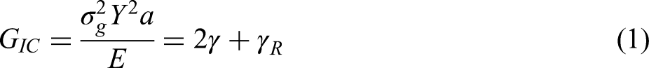
Fracture has been described using an energy balance or a stress concentration approach. Both approaches start from a semi-infinite medium with an infinitely sharp defect in it. The energy balance approach was developed first by Griffith and is based on a quasi-static stress state. The external stress applied
This approach
10
uses an asymptotic description of the displacement field to establish the evolution of the stress and strain state at the tip of a crack as a function of the defect size and geometry (Figure 2(b)). The stress evolution is described by a value called the stress intensity factor

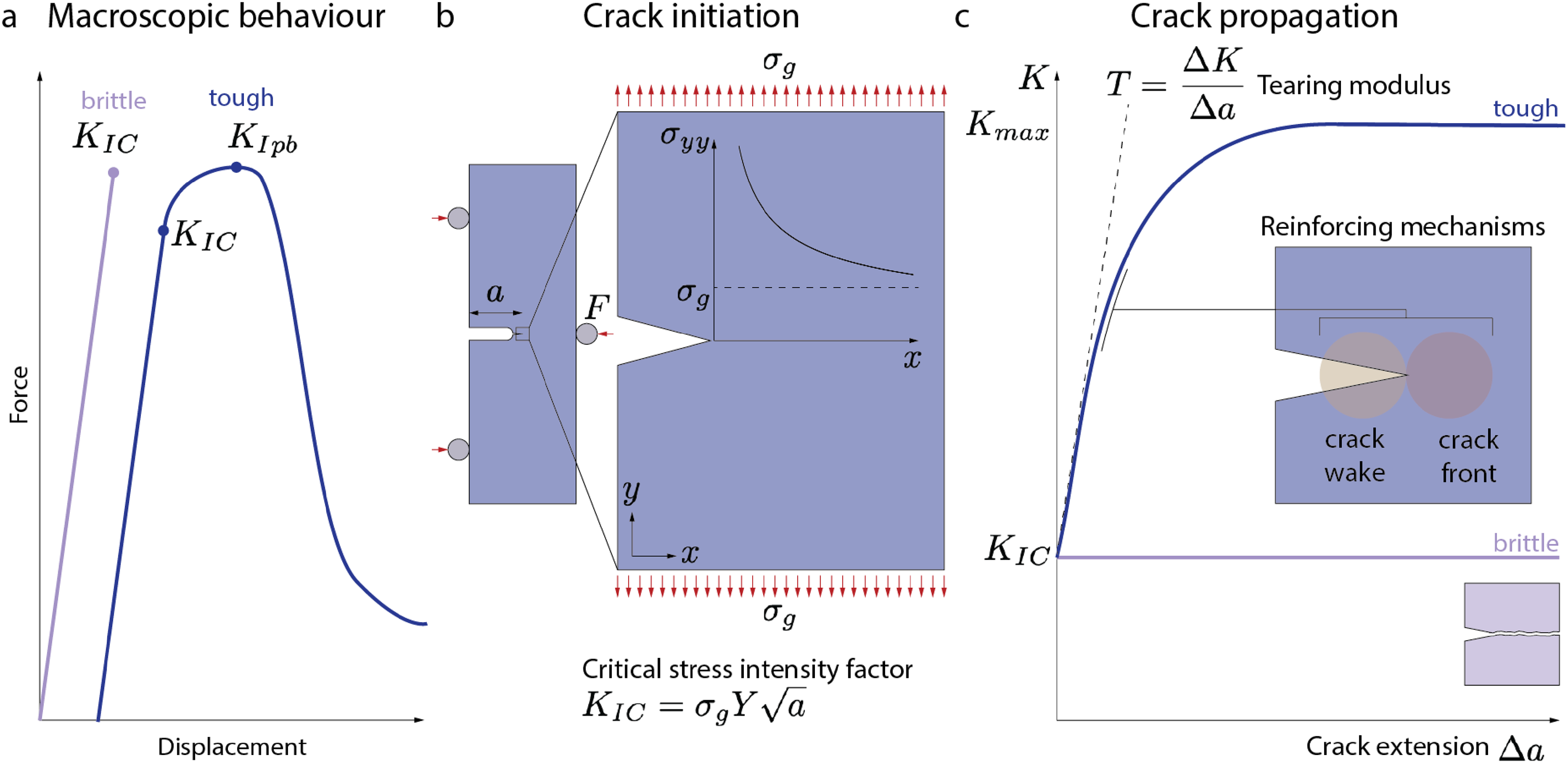
Typical mechanical behaviour of brittle materials with and without toughening mechanisms active during fracture. (a) Idealised force-displacement curves obtained during the testing of a notched specimen for purely brittle or tough materials in bending.
The applied stress
Finally, both approaches are linked and thus the critical energy release rate

Toughness and further crack propagation
Crack initiation and growth can be hindered by toughening mechanisms present within the materials. 30 To toughen ceramics, we need mechanisms that are embedded in the microstructure and will interact with the crack. 50 The main toughening mechanisms for brittle materials are crack deflection/twisting, bridging/pull-out, microcracking, and phase transformation in the case of zirconia (Figure 1(a) and (b)). Residual compressive stresses can be introduced in some parts of the microstructure to trigger crack arrest and deflection and have already been employed in bulk ceramic composites, 54 zirconia-based composites, 26 glasses 55 and ceramic laminates.56,57
The macroscopic behaviour during a typical notch beam test changes with the presence of toughening mechanisms: in brittle ceramics, an abrupt fracture of the sample happens as soon as the maximum load is reached, whereas a non-linear behaviour is observed in tough ceramic. This non-linear behaviour can be decomposed into first a non-linearity associated with crack initiation and a maximum force reached later with a more graceful failure (Figure 2(a)). Different values can be extracted from this force-displacement curve.58,59 The crack initiation toughness
In the presence of toughening mechanisms, the crack propagation will be hindered, and thus, higher stresses will be needed to keep it growing. This behaviour is captured by plotting the stress intensity factor, or energy release rate, as a function of the crack extension from an initial defect. This plot, dubbed Crack-Resistance Curve or R-curve, starts from the value of toughness at crack initiation
While R-curves represent the most accurate way to characterise the toughness and behaviour during failure, other values can be used to quantify the toughness when the crack length has not or cannot be measured. The work of fracture
The experimental determination of the R-curve is thus crucial to understanding the toughening mechanisms acting in the materials and how to influence them, but is delicate as it relies on strong assumptions. The simplest model to measure R-curves is based on linear elastic fracture mechanics and follows the same assumptions as the measurement of
Approaches to quantifying the plastic part of the energy dissipated during fracture are based on methods developed for metals and energy balance approaches. The most used one is the J-integral method,
64
but cohesive zone model,65,66 for instance, based on the Dugdale-Barenblatt approximation of a crack, can also be used. It can be proved that in the case of a linear elastic brittle solid, the J-integral is equal to the critical energy release rate, and it is seen as an equivalent of the critical energy release rate in the case of elasto-plastic materials.
10
While being a powerful tool to measure fracture toughness for elasto-plastic materials, the J-integral requires the stress and strain tensors of the sample to be calculated directly. It can thus be determined easily from simulations, but it is difficult to access experimentally. Derived from this approach, the experimental J-integral method relies on the fact that the energy dissipated during fracture can be separated into elastic and plastic contributions, the elastic part is then measured as before using equation (2), and the plastic part is estimated from the inelastic work dissipated during crack growth using numerically estimated coefficients. When this framework is used, the final toughness value obtained from the R-curve is called
The difficulty in measuring experimentally toughness and R-curves
All theoretical fracture frameworks that give access to the material R-curve start from the determination of an accurate crack length extension, which can be difficult in systems presenting multiple extrinsic toughening mechanisms. The first crucial aspect of the determination of fracture toughness and R-curve value is to start with a sharp notch. This is vital to avoid any gross overestimation of the fracture toughness as it has been proven that a dull notch could lead to as much as a 2-fold overestimation of the fracture toughness value. 68 For this reason, standards enforce to have a notch with a curvature radius lower than 20 µm to make any measurement valid, or at least a curvature radius around a few times the grain sizes.58,60 Most labs rely now on custom-made systems that use the repetitive motion of a razor blade and grinding paste to sharpen the end of dull notches done with a cutting blade. Lasers (especially femtosecond-lasers leading to ablation of material without significant damage) can also be used to sharpen notches a lot more accurately and reproducibly, but they are more expensive systems. 69 For purely brittle ceramics, a pre-crack based on indentation and control loading can also be done. 60
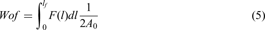
In a sample with a sharp notch, the R-curve can then be measured using the evolution of the crack length and the force applied to the sample. This crack length can be measured via different techniques, either directly or indirectly. If only one crack grows in a direction close to the direction along which the opening stresses are maximum, it is possible to measure the crack extension optically, for instance, using an optical setup, doing the test in an SEM, or even by using X-ray tomography 67 to estimate the crack dimension and shape within the sample (Figure 3(a)). A direct measurement is the best estimation possible as it does not rely on any other fitting parameters and should be preferred (Figure 3(b)). One final difficult aspect of measuring the crack length experimentally is that all the calculations used to get fracture toughness values are assuming a 2D sample. Experimentally, cracks have a 3D shape and can bow within the sample, leading to uncertainty on the crack length determination. This effect has been studied in detail for metals 70 but less in ceramics, and could use the advances of in situ tomographic reconstruction to study this effect in tough ceramics. 71
Summary of the different methods to estimate the crack growth for the determination of a material's R-curve. (a) Crack length measurement comparison using optical or electron microscopy and X-Ray tomography in a metal-ceramic composite. Reproduced with permission from Elsevier. 67 (b) Example of conditions in which a direct determination of the crack length can be made. In this situation, there is only one crack propagating in the direction of the maximum opening stress, with a zone in which the toughening mechanisms act around the crack tip, sometimes called frontal zone, that is small compared with the crack and sample size. (c) Example of conditions in which a direct determination of the crack is impossible, and thus indirect measurement must be done. In this situation, the zone in which the toughening mechanisms act is large and diffuse compared with the crack and sample size, with possibly multiple cracks growing at the same time.
However, if the crack is not unique and straight or difficult to observe, then an indirect measurement is needed. For instance, if multiple cracks are growing or if the crack is highly deflected, it becomes difficult to define a single crack length value (Figure 3(c)). All these mechanisms are unfortunately the hallmark of extrinsic toughening in ceramics. The indirect determination of a crack length relies on measuring the variation of compliance of the sample and determining a relative crack length. Any damage in the sample will increase its compliance, and from this compliance variation, a virtual crack length can be estimated. The virtual crack length is thus the equivalent, well-defined crack length that would lead to a variation of compliance similar to the one observed and relies on fitting coefficients that have been estimated in simple cases and for short crack lengths. Standards recommend the use of dynamic loading/unloading cycles to estimate variation of compliance.58,60 Unfortunately, other effects can influence the crack growth and crack length measurement. The compliance of the setup, the stiffness of the sample, and thus its size can influence the accuracy with which we can measure compliance variation attributed to the sample only. For a stiff ceramic sample of small size, the change in compliance variation as the crack grows can be too small to be measured, especially with a relatively compliant setup, and a static determination must be done. This static compliance variation is done without loading/unloading cycles by taking the variation of the slope in the force-displacement curve at each point. This determination can overestimate the change in compliance as the elastic part of the loading is not removed and should thus be used only when dynamic compliance measurement fails. 72 For all these reasons, it is difficult to accurately assess the R-curve in materials with complex fracture paths, which leads for some materials to a sample-size dependent R-curve.
Size effect on the mechanical properties of brittle materials
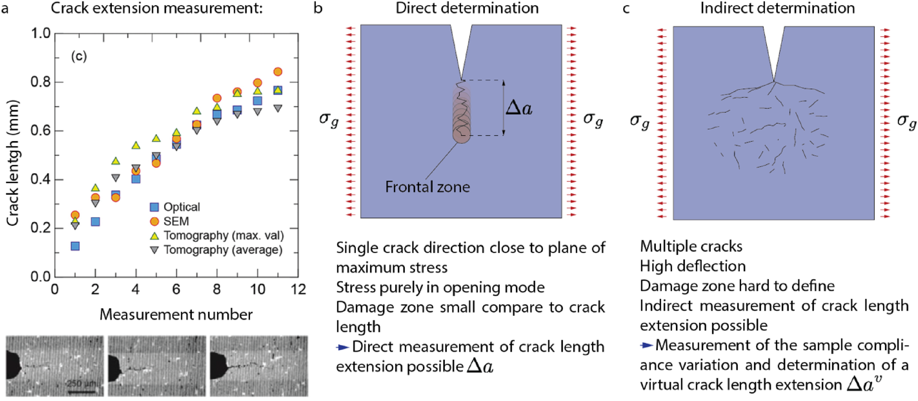
Size effects in ceramics are present in brittle materials and must be considered during structural testing. This is a direct consequence of their brittleness: a crack will grow to release the elastic energy stored during the mechanical loading of the sample. By decreasing the sample size, the largest defect that can be present in the structure will also decrease, making the sample appear stronger (from equation (2)
Strength vs. fibre diameter for glass fibres (data from reference 73 ).
The link between toughness and pseudo-ductile behaviour
Complex phenomena and experimental challenges are part of the measurement of toughness in brittle materials. While toughness measurements open an important understanding of the behaviour during fracture, it is still hard to make a direct link between toughness, the shape and value of the R-curve and the statistical strength distribution or plastic/brittle behaviour of real components, for which crack position and direction/speed of growth arise from the interaction between the defect population and the local stress tensor. Therefore, some materials with a high value of maximum R-curve toughness may break in a brittle manner during testing with notch-free samples, for instance, nacre-like aluminas (
However, it is still unclear which of the different values of toughness is more important when it comes to increasing ceramic reliability and safety. One way to see it is to say that for a brittle material to be able to stay in one piece after a crack starts from a defect, it needs to become so energy-demanding to keep the crack growing that it stops, even when the overall elastic energy is still increasing. This can then lead to another crack growing from another defect and being stopped. Based on these simple considerations, the properties that need to be increased in priority is how fast the cost to grow a crack would rise. Thus, the priority will be to increase the slope of the R-curve or Tearing modulus, as well as the maximum value reached. While this was already mentioned 30 years ago, 30 it still needs to be carefully evaluated, as no material system is available yet in which the tearing modulus can be varied in such a range as to observe this transition from brittle to pseudo-ductile behaviour.
We will see in the next parts that each type of microstructure and reinforcement mechanism leads to a different R-curve and measurement challenges while offering multiple possibilities to design more reliable ceramic-based materials.
Toughness by bridging and pull-out in SiC-based CMCs
Ceramic Matrix Composites (CMCs), in which a ceramic matrix binds together ceramic fibres, exhibit record-breaking toughness for all ceramic-based materials and are relatively notch-insensitive, exhibiting a pseudo-ductile behaviour when tested in tension. This sought-after behaviour for structural parts finds its origin in a core micromechanical concept: under load, the matrix will crack before the fibres. The fibres serve as the primary load-bearing component, while the matrix and the fibre-matrix interface play key roles in load distribution and the activation of the toughening mechanisms. This behaviour is only possible when two conditions are met: the matrix breaks at a lower strain than the fibre, and the fibre-matrix interface is weak enough to promote crack deflection along it. 78 In these conditions, a crack that is generated in the matrix will not break the fibres, leading to damage that does not compromise the load-bearing capability of the component. More toughening mechanisms can be activated when the damage progresses, with crack bridging and fibre pull-out.
CMCs are currently used in exhaust components in aerospace and industrial furnace linings. 79 SiC/SiC, for instance, can withstand temperatures up to 1400 °C and are prime candidates for nuclear fusion reactor components and gas turbine engines.5,80 SiC/SiC shrouds (or seal segments) are already being used in civil aeroengines. 27 C/SiC composites excel in applications requiring thermal shock resistance and low thermal expansion, such as spacecraft re-entry systems and high-performance brake discs.5,81,82 Ultra-High Temperature Ceramic Matrix Composites (UHTCMCs), combining materials like ZrB2 or HfC in the matrix with C fibres, push the temperature envelope even further, potentially withstanding temperatures above 2000 °C, making them ideal for hypersonic vehicle leading edges and rocket nozzles. 83
CMCs are a prime example of how the development of a tough material requires simultaneous structural manipulation over a wide range of length scales. From the macro- to micro-scales, the anisotropic microstructure (due to fibre alignment) is used to promote increasingly complex crack patterns that lead to higher toughness, but usually at the expense of strength,8,84 and to ensure a balance between strength and fracture resistance in a broad range of loading conditions and fracture modes. The challenge resides in the combination of increasingly complex fibre configurations with the shaping of intricate macroscopic parts. The most advanced configurations rely on state-of-the-art weaving and braiding 3D technologies, often borrowed from the textile industry, 85 whereas progress in the moulding of 2D plies with a matrix precursor (prepreg),86,87 and in additive manufacturing 89 could help to improve the shaping capabilities (Figure 5(a)).
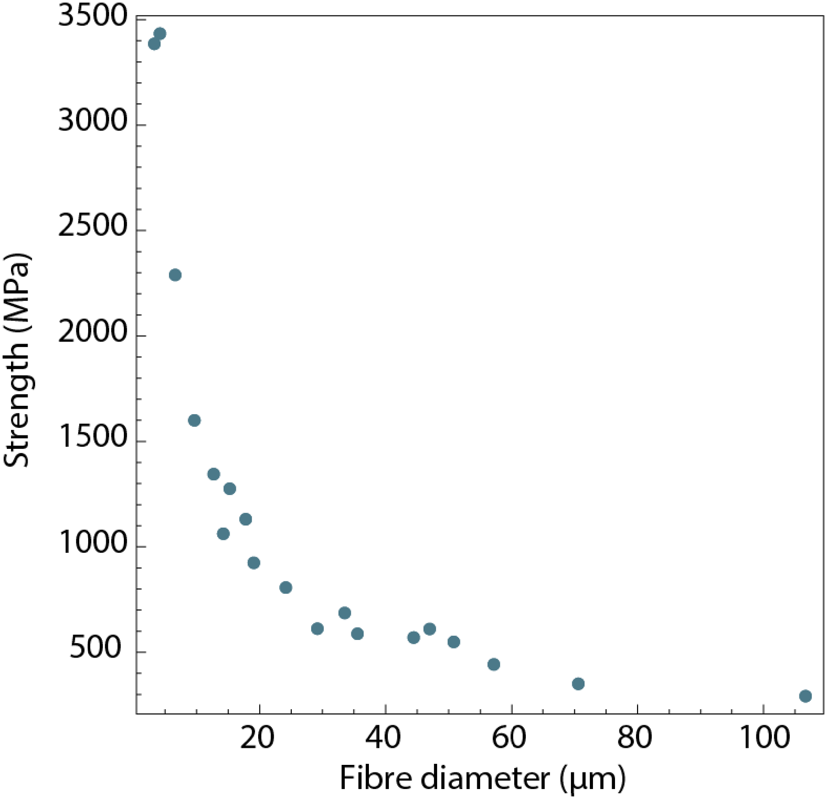
Example of microstructure and tensile properties of CMCs. (a) Schematic of a 3D woven (top) and X-ray CT of 2D woven (bottom).5,90 Adapted from 88 and with permission from Springer Nature. (b) SEM image of the microstructure of a 2D SiC/SiC manufactured by CVI and MI. Adapted with permission from Wiley. 11 (c) Fracture surface of a SiC/SiC showing the fibre pull out. Adapted with permission from Elsevier. 91 (d) Schematic showing the main micromechanical mechanisms contributing to the macroscale failure, the micromechanical properties involved in fracture (fibre-matrix friction (τ), fracture energy of the fibre, matrix and interfaces (Gc), residual stresses and the fibre tensile strength (σTSf) and detail of the main possible crack deflection mechanisms [adapted from92,93]. (e) Schematic of a representative stress-strain curve for a minicomposite tested in tension and cycled above the matrix cracking stress (σmc) and then reaching the saturation stress (σs) and final failure [adapted from 92 ]. 94 (f) Stress-strain curves for different SiC/SiC CMCs without and with different interfaces.
Due to the limited scope of this review, we will focus on the core toughening mechanism and, thus, the role of the fibre-matrix interfaces in toughening SiC-based CMCs that are currently one of the strongest and toughest CMCs. To facilitate the development of a fundamental understanding of the role of the fibre-matrix interface from the bottom up, meso- and micro-mechanical tests (e.g., fibre push out) are commonly performed in model samples called “minicomposite” in which the matrix contains a single tow/bundle of fibres. 95 Regarding fracture toughness measurements, the simplest architecture that can be used is a 2D woven composite. Our review will deal with the latest results in these model systems as the quantification of fracture is more challenging the more complex the fibre arrangement and microstructure get. More detailed information on other types of CMCs and configurations can be found in dedicated review articles.78,83,96,97
At the micro- and nano-scales, the microstructure containing fibres and matrix is designed to ensure matrix cracking before fibre fracture. Vitreous (e.g., C) or nanocrystalline fibres (like SiC) are often employed. The main high-performance SiC fibres currently used are Hi-Nicalon Type S, Sylramic and Tyranno (SA 1 and 3). This latest generation of fibres exhibits strengths ranging between 2.0 and 3.4 GPa and a stiffness of 200–400 GPa. 98 The latest generation of SiC fibres has good temperature resistance up to 1500–1600 °C and above in inert atmospheres (for example, SA-Tyrannohex does not degrade in argon up to 1900 °C). However, they may suffer significant environmental degradation at high temperatures when oxygen is present, under high humidity 99 or high neutron doses. 100 Due to their nanocrystalline nature, the toughness of the ceramic fibres is relatively low 101 (around 1–2 MPa.m1/2) 102 and their strengths at room temperature are very sensitive to defects, in particular those that can arise from processing or environmental degradation. In part to overcome this problem, fibres in composites are usually arranged in tows. As opposed to single fibres, which are brittle, the tows are damage tolerant due to the successive individual fibre breaks and inter-fibre friction. This is a result of the statistical nature of the failure of ceramics, which is represented by the Weibull modulus (m) and is linked to the statistical distribution of defect locations and sizes. 103 The Weibull modulus of SiC fibres is low, ranging from 4.5 to 8.5, resulting in a large spread in fibre strengths and, thus, a staged tow failure. 104 At the nanoscale, much effort is being placed on the engineering of the fibre-matrix interphases. The goal is for the interface to be weak enough to promote crack deflection and fibre pull-out. Examples include thin porous interfaces or ∼100 nm thin layers (called interphases or interlayers) of turbostratic carbon or boron nitride in SiC-based CMCs.
Starting from a damage-tolerant tow, a SiC-based CMC is formed by adding first the interphase and then the matrix. The interphase starts as a coating of the fibres applied using chemical vapour deposition/infiltration (CVD/CVI) or wet chemical techniques. 105 Then, the matrix is formed using either polymer infiltration pyrolysis (PIP), melt infiltration (MI) or CVI or a combination of those 106 (Figure 5(b)). This multiple-step process is what makes CMC production complex and time-consuming. The interphase is one of the key ingredients to promote toughening by facilitating crack deflection and fibre debonding. The interplay between the fracture energy of the fibre and the interface determines the degree of pull-out, while matrix-fibre friction acts as a source of energy dissipation. Using fracture energy as a criterion, it is expected that the fracture energy of the interface would have to be approximately less than a quarter of that of the fibre to enable debonding unless there is a large elastic mismatch between fibre and matrix. 107 The fracture surface of a tough CMC will exhibit substantial fibre pull-out (Figure 5(c)). However, excessive pull-out might indicate poor strength. Crack deflection at the interface can happen in three different ways (or a combination of them): inside or outside debonding and cohesive failure (Figure 5(d)). Compared to inside debonding, outside debonding leads to a longer lifetime as fibres get less exposed to the outer environments upon crack deflection. 108 Most SiC-based CMCs deflect cracks via inside debonding, as predicted by Hutchinson 107 and Lamon 109 for the case of interphases with low stiffness. Outside debonding has been observed in some SiCf/BN/SiC systems, and it was suggested that it could be the result of a very low interphase-matrix adhesion caused by the residual stresses that originated during manufacturing.
Composites with optimum interfacial properties are relatively notch insensitive and exhibit pseudo-ductile stress-strain curves when tested in tension and stable fracture (also known as “graceful failure”). Successfully enduring a tensile test without catastrophic failure is typically considered an indicator of the material's high toughness, as, unlike in bending, there are no compressive stresses that could help to stabilise the cracks. Figure 5(e) shows a schematic tensile curve of a tough minicomposite tested with the load applied parallel to the fibres. First, the CMC deforms in a linear elastic fashion until a matrix cracking stress (σmc) is reached. Then, the stiffness is reduced as multiple cracks form within the matrix. If the interfacial properties are correctly engineered, cracks will then deflect along the fibre-matrix interfaces. At larger strains, a matrix saturation point (σs) is reached and indicates that the matrix is fully cracked. Finally, the failure of the material occurs when the fibres fail. Loading-unloading tests at stresses higher than the σmc show the hysteresis behaviour of the material, which is related to the energy being dissipated by friction/sliding stress at the fibre-matrix interfacial region (i.e., fibre pull out).92,110 Recently, SiC-matrix CMCs reported in the literature have shown values of strength and matrix crack stress ranging between 300–500 MPa and 120–200 MPa, respectively.111,112
The interfacial properties have a massive effect on the bulk mechanical properties of SiC-based CMCs. For instance, Figure 5(f) shows a study by Lamon and coworkers, 94 which compares a SiC/SiC without interphase and with single or multi-layered ones, resulting in different degrees of bonding with the matrix. The work shows how strong interphases (with shear strengths ranging between 40<τ<370 MPa) produce a material with higher tensile strength and higher matrix cracking limit than a material with weaker ones (2<τ<9 MPa). New studies are now trying to determine the optimal interfacial debonding energy via customisation of the chemistry and thickness of the interphases. 113 In parallel, recent work focuses on the effect of thermomechanical exposure in different atmospheres and how it affects interfacial strength. For example, it has been shown how environmental degradation (e.g., high-temperature oxidation or recession of boron nitride interphases due to high humidity even at low temperatures) can cause significant changes in interfacial adhesion and affect the macroscopic fracture resistance. 114 There is a continuous search for new interphase compositions that will result in composites with improved mechanical performance and that can maintain it in harsh environments. Currently, BN interphases doped with silicon are preferred in SiC/SiC composites for aerospace applications. They form a borosilicate glass in oxidising environments that can heal cracks and slow down oxidation rates while retaining some degree of fibre-matrix bonding. 115 Several groups have investigated compounds as diverse as MAX phases or oxides. 105 The challenges include achieving the required compositions, thickness, microstructure and strength during the deposition process.
The potent toughening mechanisms in CMCs also introduce difficulties when quantifying the fracture resistance. We focus here only on model systems with 2D woven architecture. First, due to their orthotropic nature, fracture depends on the orientation. The interlaminar plane (the X-Y plane in Figure 5(a)) in 2D CMCs is the weakest one, and loading leading to interlaminar fracture is normally avoided in service. The other two orientations are in-plane (fracturing along the X-Z plane) and out-of-plane (Y-Z plane, Figure 5(c)). Out-of-plane toughness is generally greater than the in-plane one. For instance, in a woven 2D SiC/SiC with BN interfaces, the initiation toughness (KIC) was measured to be 5.5 and 3.2 MPa.m1/2 for the out-of-plane and in-plane orientations, respectively. 116 However, initiation toughness does not fully capture the fracture resistance of the CMCs that develop as the crack propagates. Consequently, different fracture resistance values have been reported in the literature over the last years, such as the flexural work of fracture (Wof) or equivalent fracture toughness (Keq). Keq is a parameter used to represent the fracture toughness of a homogeneous and isotropic material with the same sensitivity to crack propagation as the composite. However, both parameters may depend on loading rates and initial notch sizes. In a recent work analysing SiC/SiC composites, the Wof remained stable at around 6 kJ/m−2 at strain rates between 0.5 and 1.5 mm/min but decreased slightly at higher strain rates and was higher at lower ones. Keq remained stable for notches larger than 1 mm at values between 25–30 MPa m1/2 but decreased substantially for smaller notches. R-curves have also been used to quantify the fracture properties of CMCs. However, this approach also poses some problems as fracture is often associated with a large process zone with multiple cracking, and it is difficult to assign a crack length at a given load (Figure 6(c)). To go around this problem, Lamon et al.94,120 used the compliance method to compute an equivalent crack length in early stages of crack propagation and measure the associated strain energy release rates (G). This analysis was performed during the formation of microcracks in the matrix region close to the notch before the initiation of the main crack. In their work, they studied the influence of the testing geometry and the sample size by using Compact Test (CT) and Single Edge Notch Beam (SENB) samples. Figure 6(a) shows how CT samples of different sizes (35 × 35 × 5 vs 25 × 25 × 5 mm) and the SENB (50 × 20 × 5 mm) produce similar values of fracture toughness. Lamon et al. also reported how the bonding strength of the interface affects the toughness. R-curves were measured for a SiC/SiC with different interphases (Figure 6(b)). It was found that stronger interfaces (40<τ<370 MPa) resulted in higher values of fracture energy and higher tear modulus.92,109,110
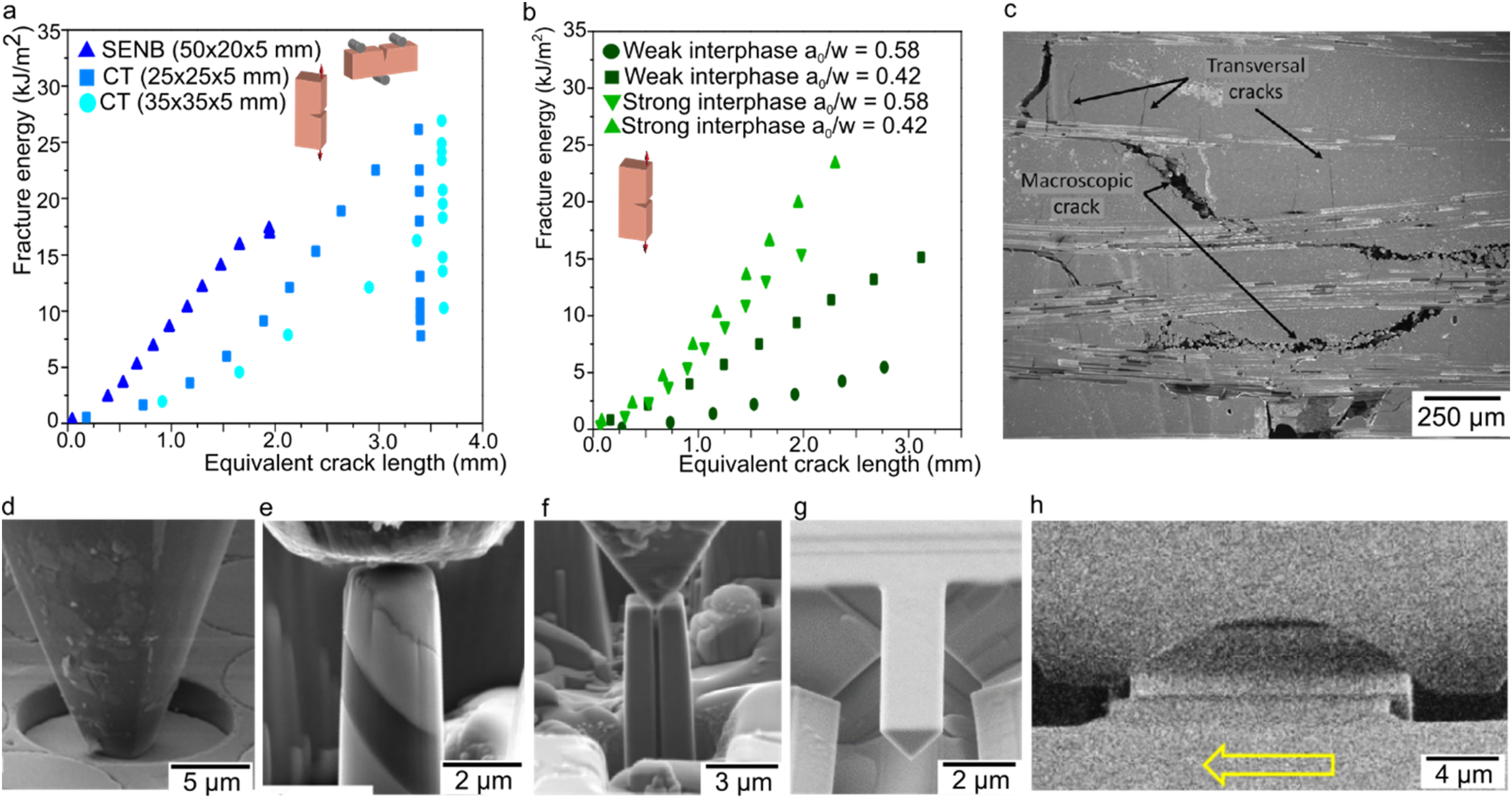
Example of the crack fracture properties of CMCs. R-curves of a SiC/SiC (a) comparing single edge notch beam (SENB) with compact test (CT) and different sample sizes 117 and (b) comparing different pre-notch sizes and different interfaces. 94 (c) SEM image showing the crack propagation mechanism in the out-of-plane direction. Adapted with permission from Elsevier. 116 Different micromechanical tests used in CMCs to measure interfacial properties: (d) push out, adapted with permission from Elsevier 118 (e) pillar compression, 113 (f) DCB, adapted with permission from Elsevier 118 (g) SCB, adapted with permission from Elsevier 102 and (h) fretting test. Adapted with permission from Elsevier. 119
Basic models to understand the effect of crack deflection and fibre bridging and pull-out on the fracture resistance of CMCs were formulated in the eighties and nineties. 92 They aim to provide quantitative relationships between the properties of the interphases (interfacial fracture strength and toughness and sliding friction) and the fracture resistance of the composites. More recently, micro-scale continuous computer models are being developed to understand damage evolution during fracture under different loading conditions.121–123 These models can produce virtual stress-strain curves that replicate the experimental ones, at least for minicomposites. However, like for the earlier work, a double challenge remains. First is how to best quantify the fracture resistance in a way that fully captures the complex behaviour of CMCs, and second, how to develop and fit models able to predict the macroscopic fracture resistance of these complex materials and guide the design of new ones.
Experimentally, a variety of new characterisation and testing techniques have been developed in recent years to capture the complex phenomena occurring at different length scales during the pseudo-ductile failure of CMCs. A range of macro- and mesoscale characterisation techniques such as Electrical Resistivity (ER),11,124 Acoustic Emission (AE) 125 and X-ray computed tomography (X-ray CT) 126 have been widely used to capture crack formation and to understand the interaction of cracks with the microstructure. Research in AE has focused on signal deconvolution to identify different damage sources (e.g., matrix cracks, translaminar cracking, etc) and locate them within the sample.127,128 X-ray computed (micro)tomography setups are being used to understand the 3D deformation and failure mechanisms and explain how cracks grow within woven microstructures when tested under different stress states such as tension, 129 shear 130 or flexion. 131 Similar testing setups are currently being used to understand the failure of other CMCs at high temperatures. 132 New trends have also started to look at using advanced characterisation and data analysis techniques to link defects at different length scales and establish a process-structure correlation. 133
Models to predict the failure of CMCs with complex geometries require the thermomechanical properties of the composite constituents (fibres, matrix and interphases), and this is particularly difficult in the case of interphases. Recent advances in micro-machining using focus ion beam (FIB) and in-situ testing in the electron microscopes have advanced the testing capabilities and opened new possibilities for accurate characterisation of these individual components and the in-situ observation of toughening mechanisms in composites. Single fibre push-out/in nanoindentation setups were also investigated in the early 90's to obtain a value of interfacial strength and friction of a single interface. 134 Since 2018, with the progress of in-situ micromechanical testing setups, new adapted tests such as in-situ nanoindentation, 102 push out/push in, 135 pillar compression, 113 cantilever bending, 102 double cantilever beam 118 and fibre fretting 119 have been used to measure accurate values of strength, friction and toughness at the interfacial region (Figure 6(d)–(h)). Common average values found in the literature for state-of-the-art PyC and BN-based interfaces in SiC-based CMCs are τ ≈ 5–80 MPa and Gci ≈ 0.5–6.5 J/m2.118,135,136 However, there is a large scatter in all these micromechanical measurements. More systematic studies are required to understand if this comes from the testing protocol used, from the variability within a CMC, or from the differences between the various CMCs tested.
Residual stresses within the fibres can form during the interface or matrix infiltration process and can affect the pull-out mechanism. Attempts to measure residual stresses have been performed using micro–Raman Spectroscopy. 137 The technique has shown potential for measuring the relative variation of residual stresses in the fibres depending on the interfaces and matrices used.
Micromechanical testing together with nanoscale characterisation has also been used to predict how complex thermomechanical exposure can change local properties and lead to premature failure. It has been shown that environmental damage (e.g., water exposure at different temperatures) in SiC-SiCf composites for aerospace can locally modify the micromechanical properties of BN interphases, causing a transition from a pseudo-ductile composite to brittle bulk failure.135,138 With the recent push for small fusion reactors, 3 similar approaches have been used to quantify the change in micromechanical properties and microstructure due to Helium implantation in the fibre, matrix and interface. It is reported how localised stress, intragranular strain, and lattice swelling correlate with the crystal structure of the different constituents.137,139,140
In CMCs, the fracture process does not involve a well-identified crack propagating in a single mode through the microstructure but rather a large process zone with multiple cracks that often depend on the loading history. The community has thus been using the pseudo-ductile behaviour measured in tension. While it does not allow to report a toughness value, providing the stress-strain curve in tension ensures that the material has toughening mechanisms and a graceful failure. Bridging the gaps between the different length scales active during the failure process while testing the materials in their relevant environments constitutes one of the big challenges of the field. From the point of view of modelling and testing, the goal is to be able to acquire enough data on the properties of the individual components (fracture resistances, strengths…) that can then serve to feed multiscale models to predict fracture behaviour. The final goals are to understand the fracture behaviour, to provide quantitative criteria that could guide the design of components and lifetime predictions and to develop new and improved materials.
Toughening by phase transformation with ZrO2
The use of Zirconia in ceramics started in 1918 for refractories, but it was only when phase transformation toughening was first described by Garvie and co-authors in 1975 that this material started to be used in high-end structural applications. 7 It is now one of the major technical ceramics both in terms of application and research, with application fields ranging from implants, thermal barrier coatings for engine components, and oxygen membranes to jewellery and kitchen wares 141 (Figure 7(a)). The structural applications were triggered by the discovery of a very potent but specific toughening mechanism. Zirconia's most stable crystallographic phase changes from tetragonal to monoclinic upon cooling. 143 Whereas phase transformations occur in numerous compounds, in the case of zirconia, it leads to large dilatant (0.0167) and shear (0.16) strains of the lattice. These volume/shape changes preclude the use of pure zirconia as samples would be destroyed during cooling due to grain transforming and expanding in different directions. 17
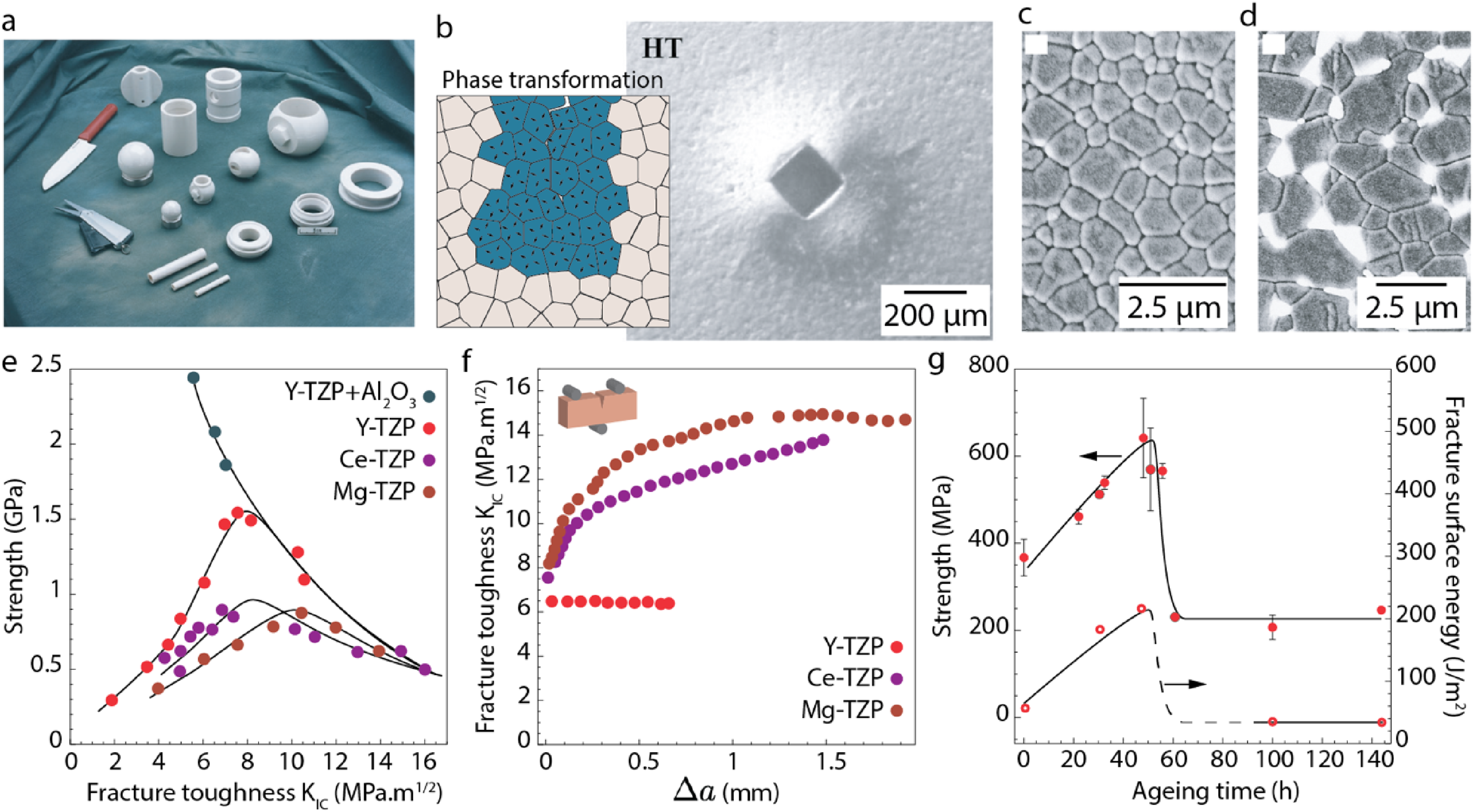
Zirconia and zirconia-based composites microstructures, reinforcement mechanism and mechanical properties. (a) Example of products using zirconia, adapted with permission from Wiley. 141 From left to right: Y-TZP kitchen knife, hot-pressed Y-TZP office scissors, Mg-PSZ components including two oil-well ball valves, butterfly valve, glue transfer roller, two small valve liners, series of three mechanical valves used in paper, chemical, and mining industries, three components used in the metal-forming industries. (b) Transformation zone around an indent in Ceria stabilised zirconia. Adapted with permission from Elsevier. 142 Blue colour represents the grains that transformed and expanded. (c) Microstructure of yttria stabilised zirconia and (d) Alumina-toughened zirconia. Alumina in grey and zirconia in white. Adapted with permission from Wiley. 141 (e) Strength vs. toughness KIC of various doped zirconia. Data from ref. 141 (f) R-curve for three doped zirconia. Data from ref. 141 (g) Effect of ageing on the bending strength and fracture surface energy of Yttria-stabilised zirconia. Data from ref. 141
Fortunately, it was then shown that the transformation temperature could be decreased down to room temperature and below with dopants that stabilise the high-temperature phase. Numerous dopants were studied in the years 1970–1990: Yttrium, Calcium, Magnesium, Calcium or Cerium were the most studied. 141 This is what makes zirconia an almost unique material: when stabilised close to room temperature, the phase transformation can be triggered under tensile stresses. 144
Because of the volume expansion and shear strain generated, this transformation can be used to stop a propagating crack by producing compressive stresses at the crack tip (Figure 7(b)). We can directly see the intimate link between the transition temperature controlled by the dopants and the ease by which the transformation can be triggered by stress. This gave rise to numerous studies over the last 40 years to establish the relationship between dopant quantity and nature, microstructure, processing, and mechanical properties. 17
While others have been studied, starting historically with Calcium and Magnesium, the most common zirconia dopant now is Yttrium (Figure 7(c)) and is used as well in the alumina-toughened zirconia used in orthopaedic applications (Figure 7(d)). This is coming from the high mechanical properties that can be achieved, with more than 1 GPa strength and the fact that it can be used for functional applications to create the oxygen vacancies necessary for ions conduction in solid oxide fuel cells. 141 The level of stress needed to trigger the transformation leads to an optimum in terms of strength and toughness. Whereas the necessary quantity of dopants varies with the element chosen, the same trends are present for all zirconia systems. Starting from high amounts of dopants, the transformation temperature is relatively low and thus necessitates a large amount of stress to be triggered. This leads to behaviour like other traditional reinforcement mechanisms in ceramics, with the phase transformation only appearing when a crack starts to form due to the high-stress field at the tip of the crack. In this dopant and transformation temperature regime, the strength is dominated by Griffith theory and flaw size, with toughness typically around 3–5 MPa.m1/2 and strength around 300–500 MPa. 143 Decreasing the amount of dopant decreases the level of stress needed to trigger it, thus increasing again the reinforcement effect, with strength and toughness increasing up to a maximum of around 1.5 GPa and 8 MPa.m1/2 for Yttrium (Figure 7(e)). 141
R-curves can be measured on these materials, leading to values similar to silicon nitride, around 6 MPa.m1/2 (Figure 7(f)). 142 At still lower dopant concentration, once transformability is easy to trigger, the behaviour stops being dictated by the presence and size of defects as the phase transformation will occur around them before the cracks start propagating, effectively shielding the materials from their effect and dictating the maximum strength of the part. Zirconia can present a ductile behaviour as grains will transform to accommodate the increase in tensile strain even before a crack starts. At this point, the strength of the material becomes dictated by the stress needed to trigger the transformation of the zirconia. This transformation stress necessary to deform the sample is quite similar in mechanical terms to the yield strength of metals. The similitudes are more profound, as the transformation under stress presents a lot of similarities with TRansformation Induced Plasticity (TRIP) found in some metals. With a decrease in dopant concentration, the toughness can keep increasing, with some values reaching up to 20 MPa.m1/2, but at the expense of a strength decrease (Figure 7(e)). This can be achieved up to a point where the transformation temperature is too close to the ambient conditions and would compromise the stability after cooling.
A trade-off is always necessary for parts made from zirconia, between high toughness and high strength, leading to another similarity with metal and, more generally, ductile materials. 50 These properties made Zirconia a perfect candidate for biomaterials and especially implants, as they could, in some applications, replace metals that would wear and trigger adverse responses in the body. It also started a series of works on the ageing behaviour of yttria-doped zirconia, as the vacancies generated by introducing trivalent Yttrium in the lattice also make the materials sensitive to ageing through the filling of the vacancy by a hydroxyl group. 145 Under certain circumstances, yttria-stabilised zirconia may age in contact with the body, with water-based species triggering the phase transformation, which in turn would create surface uplifts and microcracking (Figure 7(g)). 146 This issue was circumvoluted by the development of alumina-zirconia based composites, ranging from zirconia matrix to alumina matrix, respectively, called ATZ for Alumina-Toughened Zirconia (Figure 7(d)) and ZTA for Zirconia-Toughened Alumina. In these composites, the phase transformation associated with residual stresses can increase the mechanical properties of alumina, while the presence of alumina strongly decreases the sensibility of zirconia to aging. 26
ZTA is now widely used in orthopaedic applications as it presents high strength and reliability with less risk of ageing (Figure 7(d), (e)). Some ATZ are present in the orthopaedic field and for the process of dental implants. 26 Monolithic Yttria-stabilised zirconia is used for dental applications, such as implants, abutments, and dental restorations. In the case of implants and abutments, the main goal is to ensure high strength, long-term reliability and tissue integration. 3 mol.% yttria-doped zirconia is chosen since it presents strengths higher than 1 GPa. The risk of ageing is now mitigated by using small amounts of alumina in the starting powder. In the case of dental restoration, where aesthetics are important, compositions with a higher yttria content of up to 6 mol.% of yttria are used. This high yttria content led to a higher content of cubic zirconia, which is less birefringent. These latter compositions are more translucent but weaker as the transformation stress is increased. Above 5 mol.% yttria, indeed, the extent of transformation toughening is minor around room (or body) temperature. Yttria-doped zirconia with still a larger amount of yttria are used for other applications, such as thermal barrier coatings, solid electrolytes or transparent ceramics, but transformation toughening is no longer the rationale for their use.
In recent years, the dopants that could trigger transformation-induced plasticity are being revisited as a way to produce more reliable zirconia-based ceramics for diverse applications. The stabilisation of the tetragonal phase can be done through two major schemes, either by creating oxygen vacancies as is the case with doping zirconia with Y3+ or by increasing the distance between oxygen and zirconium ions in the lattice using large cations like Ce4+.147,148 Both strategies lead to a decrease of oxygen ions density around zirconium ions, which tends to stabilise the tetragonal phase. Using, for instance, Ce-doped zirconia, the tetragonal phase is stabilised through lattice expansion rather than vacancy formation, which needs a larger content of dopant (e.g., 12 mol.% of CeO2 instead of 3 mol. Of Y2O3), but makes the composition much less susceptible to ageing.141,142 Transformation-induced plasticity occurs when the transformability is high enough, and thus, the dopant contents are low enough so that the defect presence is not the limiting factor for the material's strength. Additionally, the ease of transformation coming from this dopant allows for a larger zone of transformation around the defects, typically reaching 100 µm compared to the few microns obtained with Y-zirconia.17,142 This large transformation zone manifests itself visibly during mechanical testing. For instance, the volume increase is visible around indents (Figure 7(b)), in front of the crack tip during fracture testing (Figure 8(c)), or even on the tensile side in the four-point bending sample (Figure 8(d)).
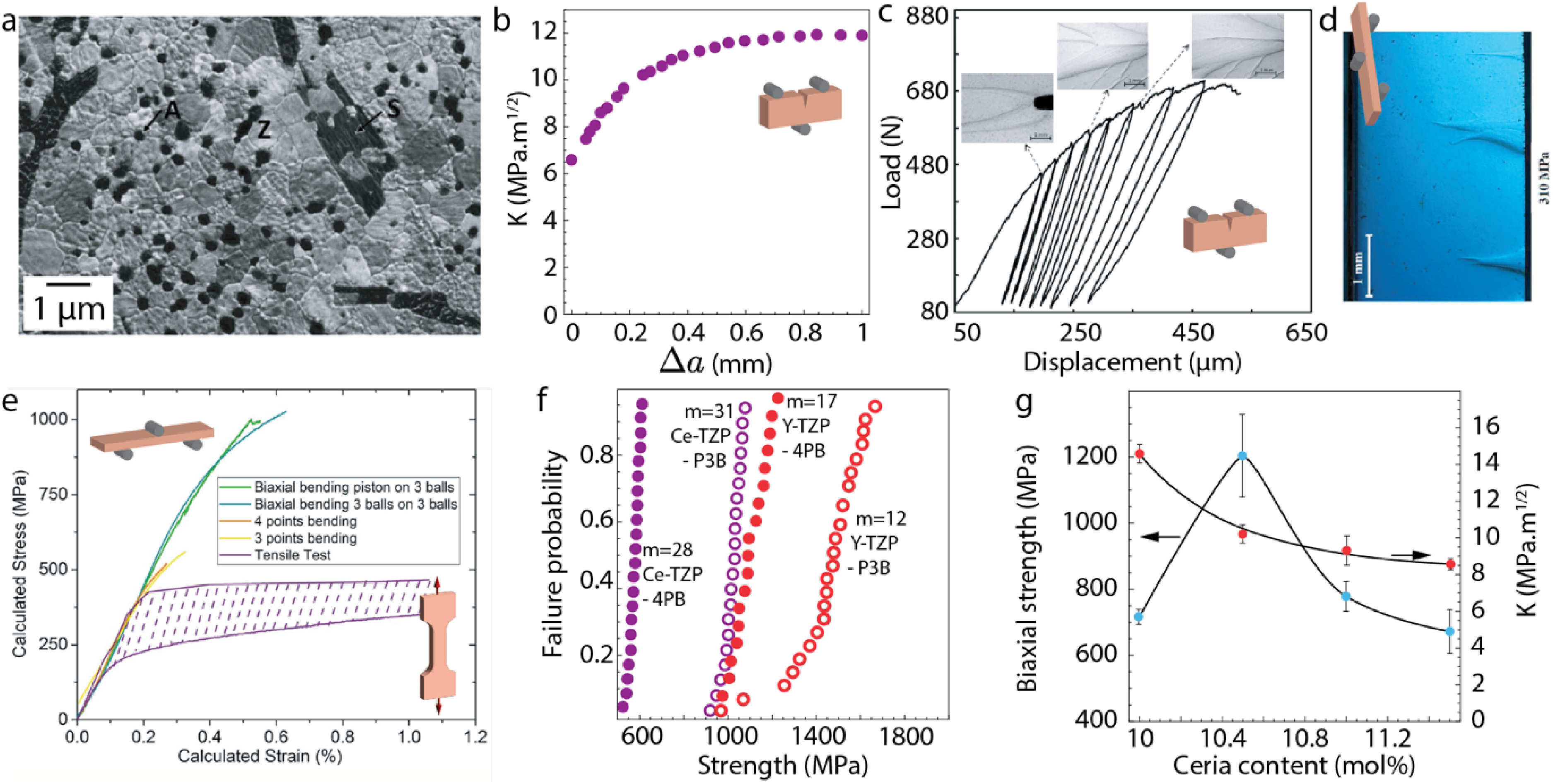
Ceria-doped zirconia as a ductile and reliable ceramic. (a) Microstructure and (b) R-curve of the ceria doped zirconia with alumina and strontium particles. Adapted with permission from Elsevier. 142 (c) Force-displacement curve of the zirconia composite during cyclic loading. Adapted with permission from Elsevier. 142 (d) Optical images of the transformation zone in the tensile side of a specimen tested in three-point bending. Adapted with permission from Elsevier. 142 (e) Stress-strain curve in a zirconia composite tested in different configurations. Adapted with permission from Elsevier. 17 (f) Weibull modulus of different compositions of doped zirconia. Data taken from ref. 142 (g) Effect of the Ceria content on the mechanical properties of ceria-doped zirconia composites. Data taken from ref. 142
Raman spectroscopy was also used to confirm the presence of compressive stresses generated around the transformed zone. 149 Fracture toughness measurements have been made on these compositions, with toughness starting from around 8 MPa.m1/2 and rising to around 12 MPa.m1/2 after a millimetre of crack propagation (Figure 8(b)). 142 In a SENB test, the transformation zone forms at the tip of the notch and is shaped into a distorted ellipsoid. 150 The zone forms before the crack starts propagating, with dimensions over 80 µm in width and a length of 900 µm for the toughest compositions (Figure 8(c)). This confirms the formation of crack shielding mechanisms well before the crack starts and explains why this mechanism could shield defects from generating cracks in large specimens. The zone can then increase in size as the crack propagates with a width tripling in size to 300 µm and more than 3 mm in length.
While the value of the R-curve can inform us of the actual mechanisms at play and give an idea of the size of the process zone necessary to shield one critical defect, the behaviour in bending or even in pure tension is the most striking, showing significant irreversible strain before crack propagation.17,141 During bending, the materials display large wedges of transformed zirconia on the tension side (Figure 8(d)). Each of these wedges helps accommodate the tensile strain and allows for the ductile behaviour of the Ce-zirconia. Instead of failing in a brittle manner, such zirconia can present a non-linear stress-strain curve and plastic strain of around 0.5% in tension or 4-point bending (Figure 8(e)) and up to 1% in biaxial bending due to the specific stress field (ref.10). This strain at failure is still below the one that can be obtained with CMCs and is limited to a certain temperature range, but is better than all other tough ceramics by an order of magnitude as we will see later. Also, in comparison to CMCs, strengths are generally higher (600–800 MPa) with highly transformable Ce-TZP ceramics and composites, which bridges the gap between high strength (Y-TZP) and high toughness (CMCs) ceramic-based materials. This plastic strain can be accommodated by the increase in volume taking place during phase transformation, and it can be demonstrated that the shear component is mainly responsible for this. 17 The pseudo-ductile behaviour is also present during tensile testing, with a similar strain at failure. 142 Similarly to CMCs, this ductile behaviour leads to very unusual properties for Ce-zirconia, with, for instance, demonstrated flaw tolerances and consequently high Weibull modulus. The Weibull modulus can reach up to 30, getting close to metals in terms of strength reliability, double of Yttria-zirconia and almost an order of magnitude higher than conventional technical ceramics (Figure 8(f)). 17
While these properties make Ce-zirconia an interesting structural ceramic in terms of reliability and toughness, the strengths obtained still limit its range of application. As discussed before, in this dopant regime, the strength of the materials is limited by the stress necessary to trigger the transformation. The stress necessary to trigger the transformation is dependent on the grain size, with a smaller grain size leading to higher transformation stresses. Unfortunately, retaining small grain sizes in Ce-zirconia has been notoriously difficult, with grains in the micron range typically obtained with conventional sintering compared with grains of 150–300 nm obtained for yttria-stabilised zirconia. Several phases, such as alumina to strontium aluminate platelets, 149 have been added to pin the grain boundaries during sintering and avoid grain growth.
Now, compositions based on 11 mol% ceria, 8 vol% alumina and 8 vol% strontium aluminate platelets lead to zirconia grains of around 1 µm and a strength of around 600 MPa with 0.5% of plastic strain (Figure 8(a)). 142 The challenge for zirconia-based ceramics is now to increase the material strength, so decreasing the grain sizes without compromising the transformability of the phase. There are already solutions going in that direction, with the addition of alumina and strontium in Ce-TZP and by lowering the amount of yttria down to a few percent to increase the transformability of Y-TZP and push them at the boundary between ductile and brittle behaviour. 151 The recent development of Zgaia powder from Tosoh, exhibiting a yttria content of only 1.5 mol.% yttria, allowed for processing at relatively low temperatures of zirconia ceramics, offering an attractive combination of strength (1 GPa) and toughness (8.5 MPa.m1/2, measured by Single Edged V-Notched Bending tests), near the optimum between a brittle and ductile behaviour. Finally, these transformation-based zirconia can only be used around room temperature as the transformation temperature is around 200°C. A possible silver lining is that a short heat treatment after damage could reverse the transformation, leading to a shape memory effect. That way, these ductile ceramics could start providing solutions for the most stringent structural problems occurring at room temperature.
It is also striking to note that the theoretical maximum strain reachable thanks to t-m transformation would reach several percent (a shear strain of 16%), while macroscopic polycrystalline samples do exhibit so far less than 1% maximum strain. Recent compression tests (Figure 9) on micro-pillars have confirmed that large strains (up to more than 10%) could be accommodated without failure on zirconia single-crystal samples oriented with their (100)t planes at 45° from the compression axis (maximum shear stresses on that planes, and along the <010 > directions). 152 On the other hand, micropillars with orientations leading to a Schmid Factor for the (100)t and <010 > t system close to 0 were breaking in a brittle manner at low strains. In macroscopic samples, only a part of the grains are transformed, depending on their orientations, and micro-cracking can occur at the boundary between transformed and untransformed grains. Therefore, there are still some drivers to increase the ratio of transformed grains using crystal orientation and texturing, but also to decrease the risk of micro-cracking by working on grain boundary accommodation and by limiting the interface strains, as it has been widely applied in metallic shape memory allows by tuning transformation hysteresis. 153 Last, if yttria and ceria-stabilized zirconia ceramics and composites are still the most widely studied to develop ductile inorganic materials thanks to transformation-induced plasticity, the further quest towards innovative compositions and even new systems could be supported by current artificial intelligence and combinatory approaches (Figure 9).
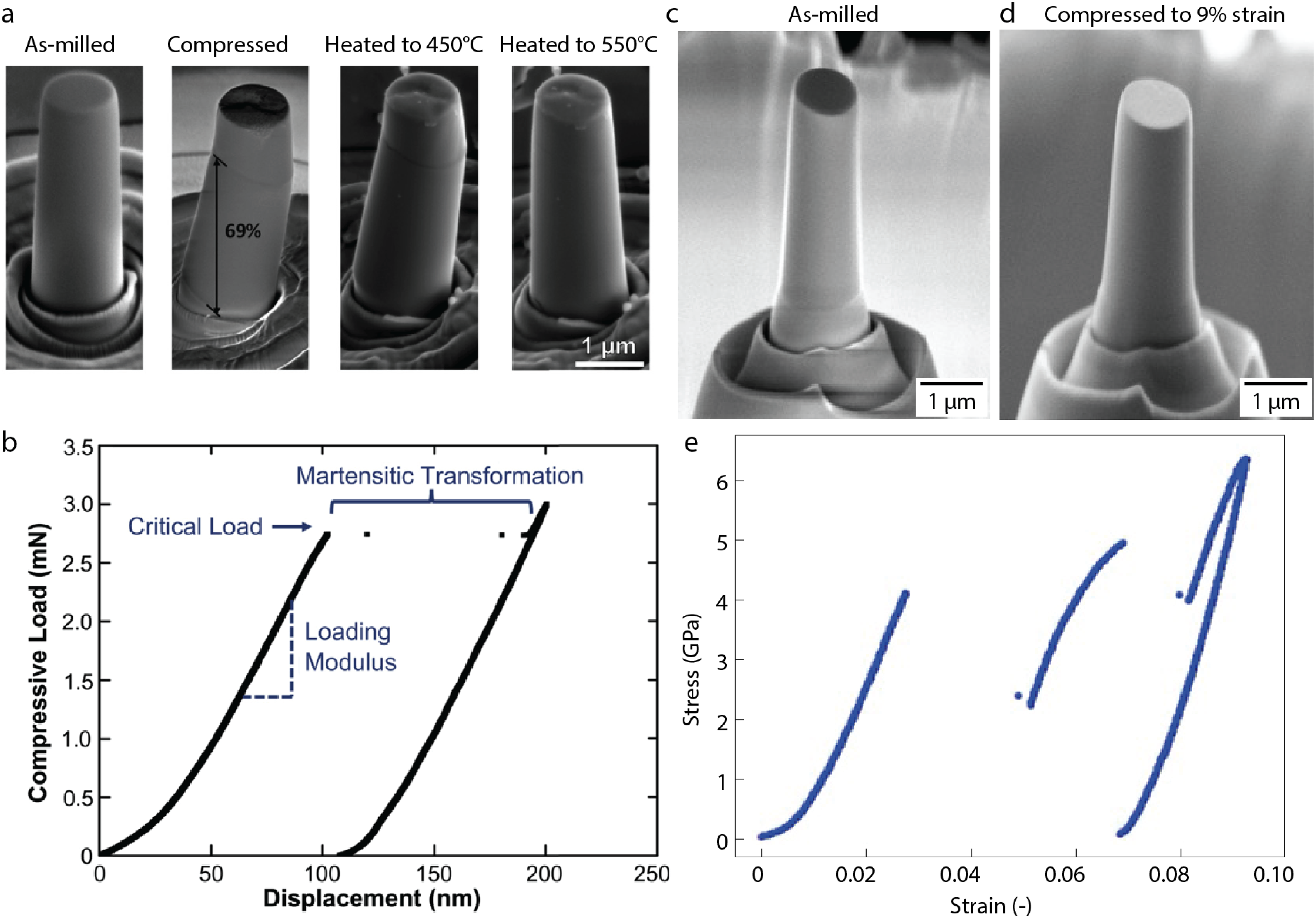
Transformation induced plasticity and shape memory effects in zirconia at a small scale. (a) Adapted with permission from Elsevier: 152 Micropillar of a yttria-titania doped zirconia after milling, compression loading, and then reheating. Note the reversibility of the transformation. The load-displacement curve was obtained under load-control conditions, the transformation leading to a sudden displacement (permanent strain estimated to 2.5%). (c) to (e): Micropillar of a 12 mol.% Ceria-doped zirconia tested under compression with a Schmid factor of 0.44 for the (100), < 010 > system, showing large plastic strain (>6%) without any damage. The load-displacement was measured under displacement control mode, the two transformation events leading to sudden load drops (Courtesy M.D. Magalhaes, T. Douillard, MATEIS INSA-Lyon and S. Comby-Dassonneville IM2NP Univ. Aix Marseille).
Toughening based on microstructure engineering
Reinforcement through elongated grains in SiC and Si3N4
In parallel with the work on tough CMC and zirconia-based ceramics, significant research has been poured into making tougher bulk ceramics using only microstructural changes. While the toughness of ZrO2 is now high enough to provide certain transformation-induced plasticity before failure and thus a real improvement in terms of defect resistance and reliability, the transformation toughening used is intimately linked to the composition and temperature and thus cannot be transposed to other composition or used in a large range of temperatures. With CMCs as well, they present impressive properties but are difficult to process. However, reinforcement mechanisms such as deflection, bridging, and pull-out can occur at multiple length scales and are not limited to the long fibre reinforcement type compositions.30,154 Toughening mechanisms can be activated at the length scale of individual grains in polycrystals. Changing the grains’ shape also means that bulk processing techniques can be used, potentially leading to faster, cheaper, and easier processing for complex geometries.
The presence of anisotropic, elongated elements in the microstructure is necessary to maximise crack deflection, bridging, and pull-out mechanisms. These elongated grains must be either added or formed in situ. The first successful example of microstructurally toughened ceramics18,155 were silicon nitrides29,156 and silicon carbides 157 (Figure 10(a)). The R-curve for these materials can initiate around 5 MPa.m1/2 and reaches values of about 10 MPa.m1/2 after 0.5 mm of crack propagation.13,18 While the toughening mechanisms are less potent than those achieved with long fibres due to the limited bridging length posed by the grain size, remarkable properties were obtained. The steep increase in the R-curve (Figure 10(b)) while retaining a strength on the order of 1 GPa is remarkable, considering the easiness of the processing used. This raised the attention to numerous projects, for instance, the idea of making a ceramic car engine.77,155 In these materials, the control of the grain boundary phase becomes even more vital, as glassy phases promoted the growth of elongated grains but also provided a weaker interface to foster intergranular fracture. Similarly to CMCs, the orientation of the elongated grains can now influence the fracture toughness, with deflection at angles potentially up to 90° as well as bridging/pull-out. 21 Most processes cannot easily control the orientation of grains in bulk ceramic besides extrusion and tape casting, and thus, most structures do not show extensive preferential orientation. Despite these achievements, the macroscopic behaviour in flexion is still linear elastic brittle (Figure 10(c)).
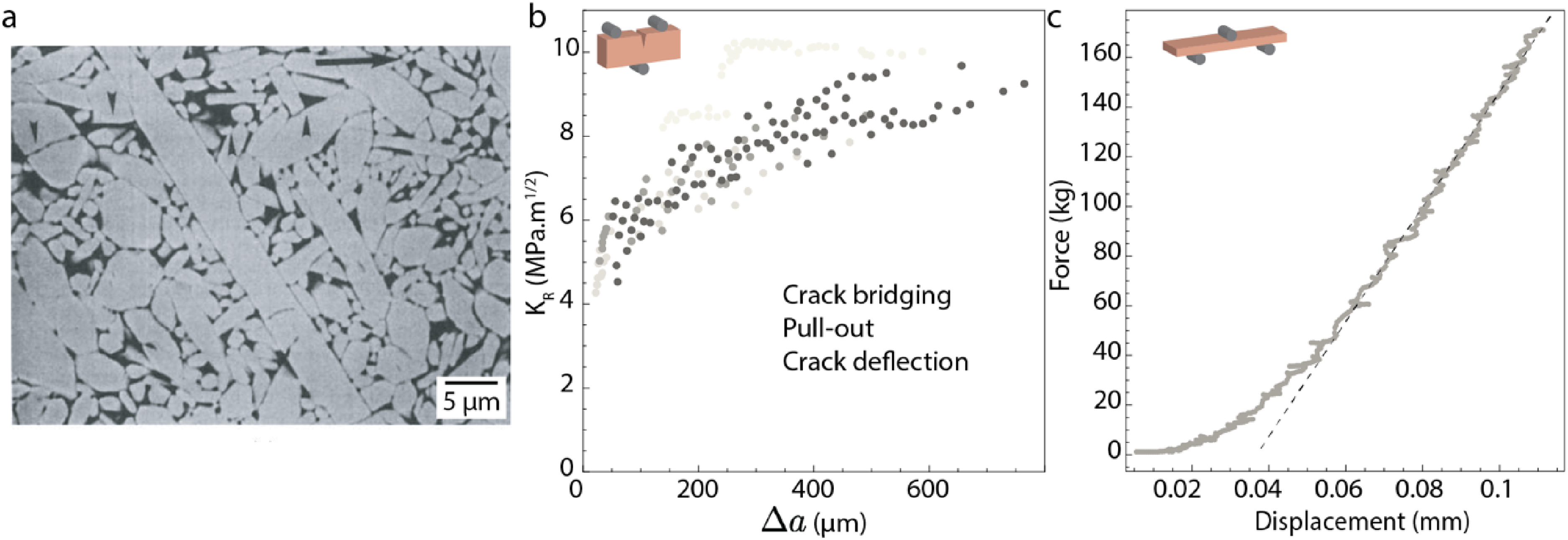
Example of microstructure and crack resistance of bulk ceramics with elongated grains randomly oriented, here Si3N4. (a) SEM image of a chemically etched Si3N4 microstructure, adapted with permission from Wiley. 158 (b) R-curves Si3N4 ceramic processed with different additives, data taken from ref.76,158,159 (c) Force-displacement curve of three-point bending specimen of Si3N4, data taken from. 77
Reinforcement through the addition of carbon allotropes
The use of whiskers and nanoparticles to toughen ceramics has been extensively explored since the eighties. 33 Overall, toughening has been attributed to crack bridging effects and, in most cases, it was relatively modest. More recently, the discovery of carbon nanostructures (nanotubes and graphene) led to their introduction into ceramic composites. 33 These carbon-based nano-objects present some of the highest strengths and stiffness ever reported. Thus, the rationale was to reinforce the grain boundary of common structural ceramics and to add bridging opportunities along the crack path.
There is a vast amount of data available on composites in which the carbon structure is dispersed in between ceramic particles, and the reader is redirected to a recent review for more details on the last 20 years of research on these structures. 34 However, there is a large spread in the measured values, probably originating from the different sources and structure of the carbon nanomaterials, their state of agglomeration and the use of different tests. The values are also obtained in most cases using indentation. However, work with composites with a high density of highly aligned nanotubes shows evidence of bridging leading to stable crack propagation in micromechanical tests, 160 and recent measurements using SENB tests seem to indicate a limited R-curve behaviour 161 in graphene/ceramic materials. 162 Recently, similar approaches have been used with 2D BN nanoplatelets with similar results. 163 In all cases, there is a fundamental limitation, and although there is some evidence of nanotubes or graphene bridging the crack, 164 their small dimensions will limit the bridging distances and, therefore the degree of toughening, as was observed for the original nanocomposites that used ceramic or metallic nanoparticles. 33
Since 2017, from this body of research and with the advancement of new colloidal processing techniques, a different strategy has emerged for using graphene as a reinforcement in ceramics (Figure 11(a)).166,167 The graphene flakes are first assembled into an orientated porous network that can then be infiltrated with a ceramic, in this case, a silicon oxycarbide pre-ceramic polymer. The flakes can also be oriented in one direction using a filtration technique. The final composites this time displayed an R-curve behaviour (Figure 11(b)), with values of crack initiation ranging from 2 MPa.m1/2 to 7 Mpa.m1/2 and almost doubling over a crack propagation distance of 400 µm. 167 With these composites, the graphene flakes were used as a weak interface to introduce crack deflection while at the same time helping the formation of bridges in the crack wake. A similar strategy has been used with alumina/graphene composites or by using graphene to create weak layers in laminated materials. 166 Once again, this is rarely reported in articles, and despite the rising R-curves, the samples seem to display a linear elastic brittle behaviour when tested in three points bending without a notch (Figure 11(c)).
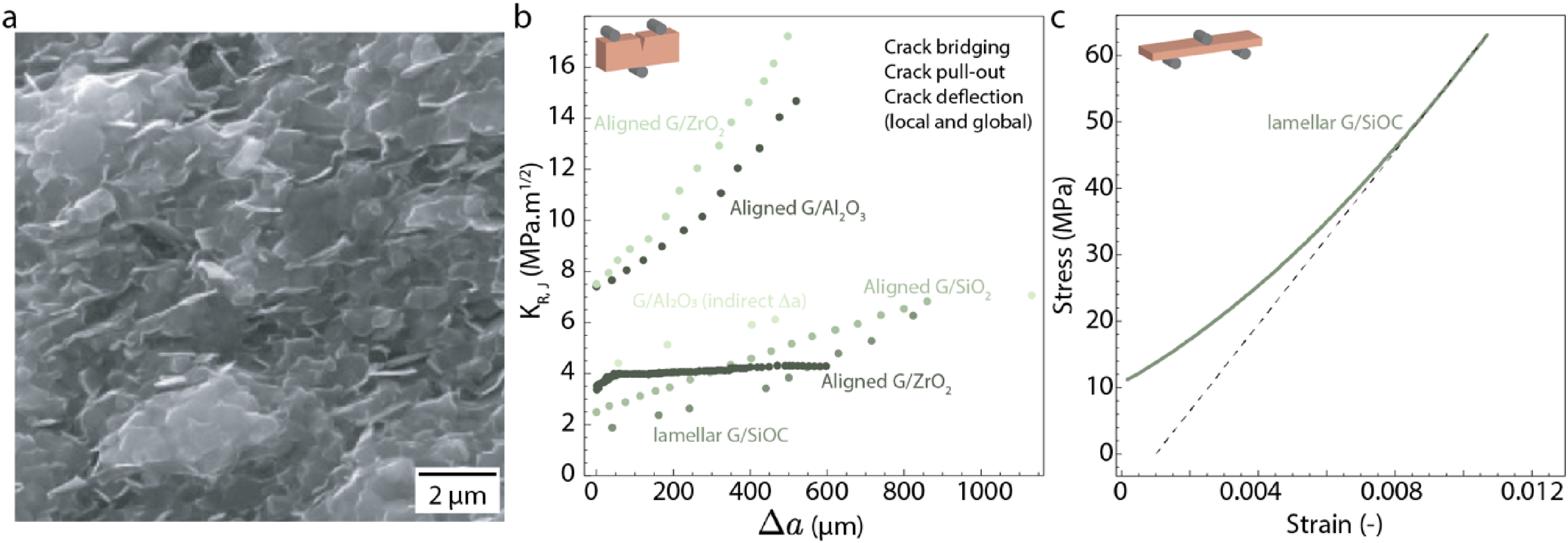
Example of microstructure and crack resistance of bulk ceramic reinforced with graphene flakes. (a) SEM image of an alumina-reinforced graphene, reproduced with permission from Elsevier. 165 (b) R-curves for various ceramics with graphene oxide either aligned or assembled into a lamellar network. Data from ref.166,167 (c) Stress-strain curve of a SiOC + lamellar graphene network composites from ref, 167 data kindly provided by Dr Victoria Garcia-Rocha.
MAX phases and iono-covalent/metallic bond-based solids
In parallel to these pure iono-covalent bond-based materials, a field of research based on crystallographic phases comprising a mix of iono-covalent and metallic bonds started. A part of this family of compounds, dubbed MAX phases, crystalises into relatively tall lattices in which layers of carbides or nitrides alternate with layers of atoms with some metallic bonding characteristics.168,169 The first goal of these materials was to use these metal-like layers to introduce intrinsic toughening mechanisms, such as dislocation movements while maintaining ceramic characteristics of high hardness and temperature resistance with the ceramic layers.
19
While a plethora of compositions are thermodynamically stable, with different stoichiometry of the different atoms in the lattice (312, 211, etc..), the most studied composition is Ti3SiC2. The mechanical properties of MAX phases have been extensively measured under compression or using indentation, and as before, the reader is oriented towards dedicated review and books for a more exhaustive exploration of their properties.19,168,170 The specific bonding in these materials seems to introduce some ductility in monocrystals tested in compression, but the exact toughening mechanisms acting in polycrystals in compression are still debated.
171
The typical microstructure of a polycrystalline MAX phase is provided in Figure 12(a), with the presence of elongated grains randomly oriented. The initiation toughness
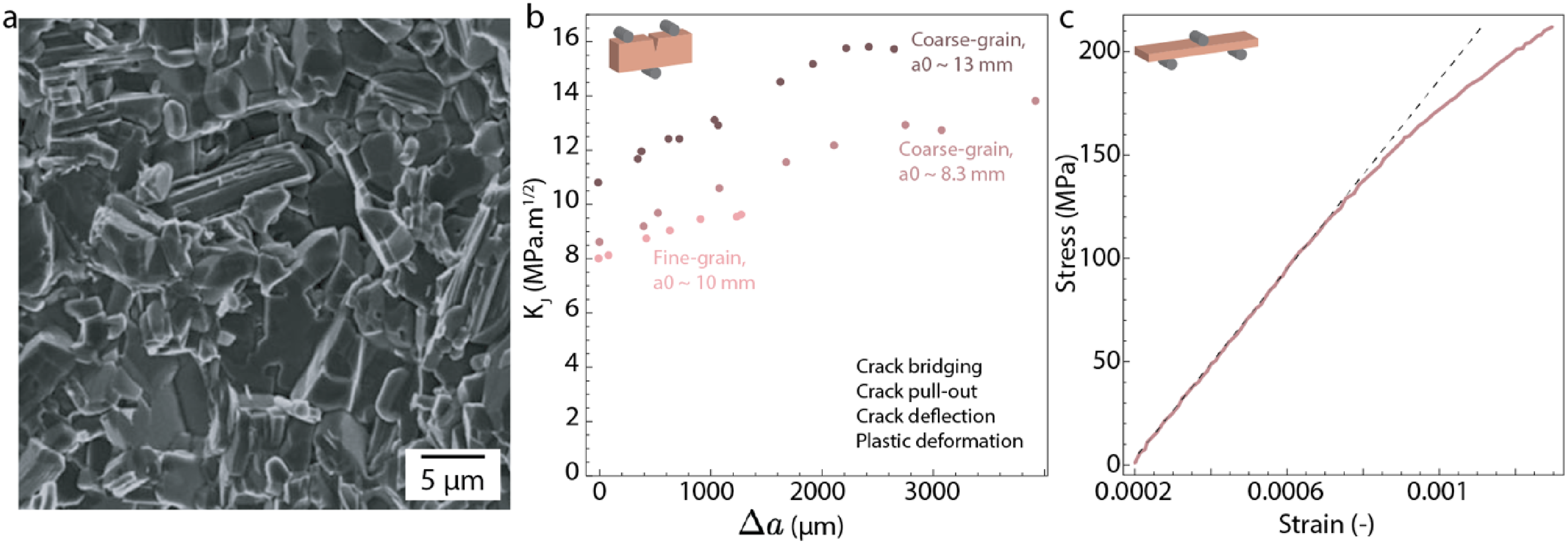
Example of microstructure and crack resistance of MAX phase ceramics. (a) SEM images of the fracture surface in Ti3SiC2, adapted with permission from Wiley. 172 (b) R-curves of a Ti3SiC2 with different grain sizes, data taken from ref. 173 (c) Stress-strain curve in three-point bending of Nb4AlC3 MAX phase, data taken from ref. 174
What natural structural materials can teach us?
These examples of bulk tough ceramics are all based on a few different mechanisms, mainly grain bridging and local crack deflection, but none present the pseudo-ductile behaviour seen in zirconia-based ceramics or CMCs. Either these mechanisms are not potent enough on their own, or additional mechanisms are needed to deeply alter their structural behaviour.
The answer to this open question could lie in natural materials. The field of bioinspiration and the understanding of natural material's structural behaviour has now provided a lot of noteworthy examples of tough structures,39,41,176 from the shells of marine molluscs177,178 to the club of the mantis shrimp,179,180 and more recently to the ironclad beetle. 181 Whereas all these structures present complex structural features at different length scales and interesting structural behaviour, there is an example that stands out: nacre, a part within mollusc shells. Nacre is constituted of a brick-and-mortar structure (Figure 13(a)), with bricks made mainly from CaCO3 in the crystalline form of aragonite and mortar made from biopolymer containing chitin.178,184,185 What researchers discovered in the 80s is that nacre presents a pseudo-ductile behaviour when tested in tension/bending, with plastic strain reaching 0.7% and yield stress of around 70 MPa37,186 (Figure 13(c)). These structural properties in tension represent a 17-fold improvement over MAX phase's plastic strain and is on par with CMCs, with a yield strength 41% lower but a plastic strain almost equal to the toughest systems. This is even more impressive considering that nacre is made from a mineral that is 6 times softer, 3 times more brittle and weaker compared to SiC, the main constituent in most common CMCs. This discovery sparked a continuous interest since then, with numerous studies done to pinpoint the origin of this pseudo-ductile behaviour.
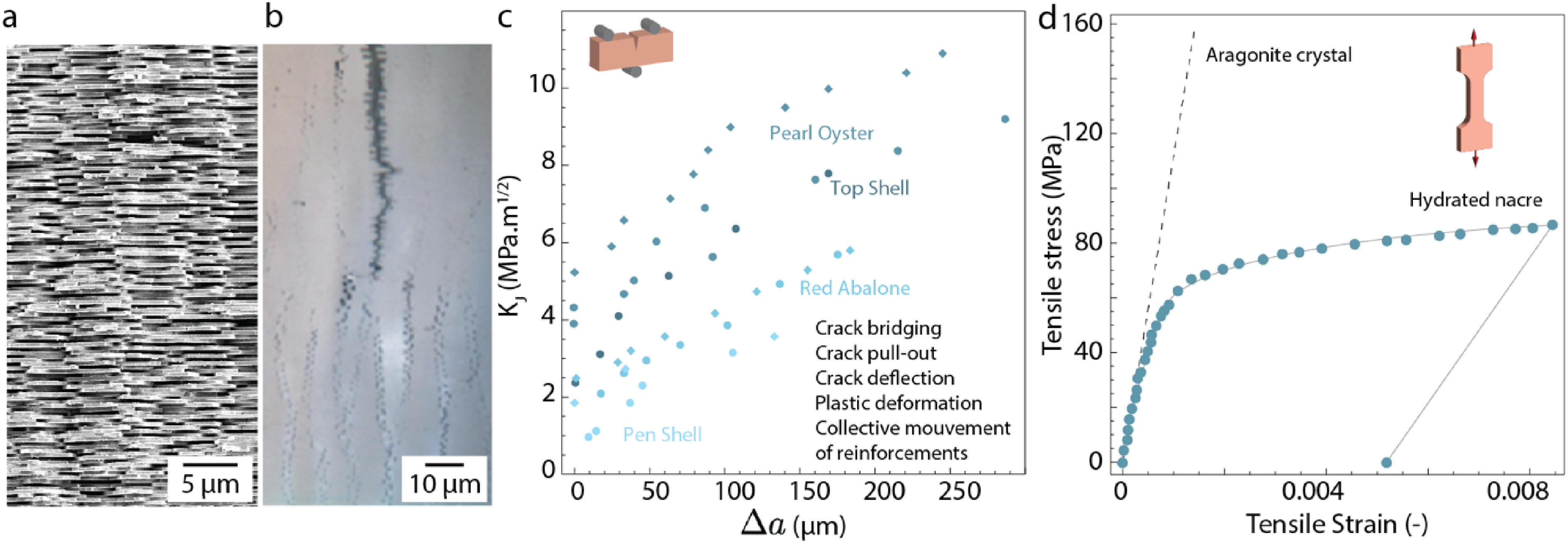
Mechanical behaviour and fracture resistance of natural nacre. (a) SEM images of nacre. Courtesy of Dr Tobias Niebel. (b) Optical microscopy image of the crack tip in a nacre sample showing the collective platelets movements, adapted with permission from Elsevier.
182
(c) R-curves obtained from different species of nacre. Data taken from ref,
182
the formula
Given the existing body of work, only a summary is given here, but the reader can be directed to these references for more details.39,40,176,187 There are multiple reinforcements present in the structure, with local deflection, bridging, and pull-out at the platelets level, like ceramics with elongated grain. There is also friction acting at the interface from the organic layer and asperities, and tablet dovetailing creates interlocking mechanisms during pull-out. 177 For all the similarities present with typically reinforced ceramics in terms of mechanisms, nacre stands out in two aspects: the presence of interlocking mechanisms and the perfect packing of the assembly, with platelets fitting snuggly together and with dispersion in thickness extremely small. These two features are thought to be central to creating a local strain-hardening effect and, in turn, the formation of diffuse damages, but unfortunately, they are also the hardest to replicate.
When tested in tension or fracture, this combination of reinforcement leads to a collective sliding of platelets leading to multiple small cracks opening, instead of a single crack growing182,188 (Figure 13(b)). While it is difficult to pinpoint one mechanism responsible for this behaviour, this spread-out damage is in turn believed to be responsible for the pseudo-ductile behaviour, as a single crack cannot propagate directly through the structure.
189
In terms of toughness and R-curve, different species of nacre, thus different microstructures, present distinct capacities to resist crack propagation. The
Numerous studies have aimed at mimicking the structure of nacre at multiple length scales and with the introduction of multiple toughening mechanisms.14,190–193 However, no materials have yet been made that present this collective platelet sliding and pseudo-ductile behaviour with high mineral content, and thus, this type of toughness amplification.
Nacre-inspired ceramics
While obtaining this pseudo-ductile behaviour in bioinspired ceramic is still out of reach, the attempt at mimicking this structure with ceramic materials leads to promising developments.
We will only limit ourselves to materials with only ceramic constituents for this review, while more complete pictures of nacre-inspired composites have been reviewed elsewhere.14,190–193 The first example of nacre-inspired ceramic was made by laminating sheets of ceramics with a weaker interface. 22 This led to large-scale deflection at the weak interface and less brittle behaviour. Toughness is hard to measure properly due to the large crack deflections. Instead a Wof of 4625 J/m2 was measured for these laminates, representing a 75-fold increase compared to the constituent GIC of 62 J/m2. More recently, this strategy has been employed with bricks at smaller length scale and with graphene used as a weak interface, leading to the toughness of 6 MPa.m1/2 compared with 0.8 MPa.m1/2 for the main constituent SiOC 167 (Figure 14(b)). Since 2014, laminated structures have been improved upon by adding residual compressive stresses as crack arresters in composition made from alumina and alumina zirconia layers.56,199
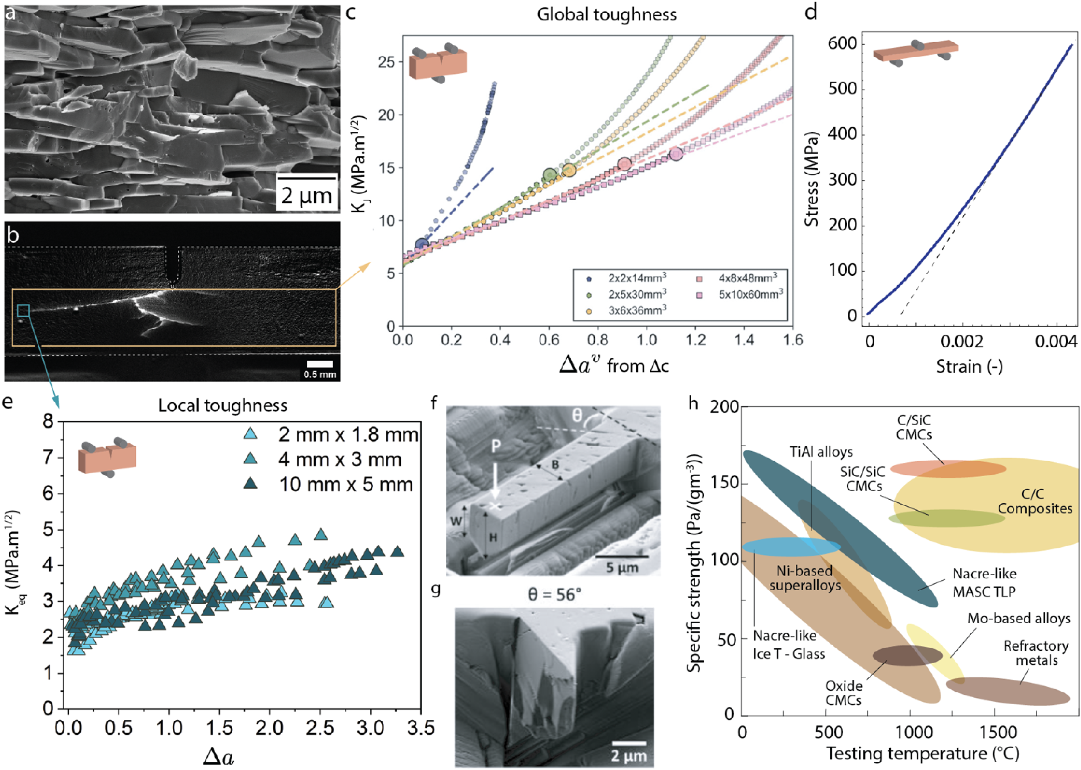
Example of microstructure and crack resistance of nacre-like alumina (a) Fracture surface of NLA obtained by MASC. (b) optical images with background correction of the fracture pattern of NLA obtained by MASC, adapted with permission from ref. 194 (c) R-curves of NLA obtained with the compliance method with different sample sizes, © (2020) H. Saad et al. (10.6084/m9.figshare.11907276) CC BY 4.0 license. 195 (d) Stress-strain curve of NLA obtained by MASC. (e) Local R-curve obtained from the kinked crack theory of one deflected crack, reproduced with permission from ref. 194 (f and e) Small-scale cantilever beam sample machined by FIB into NLA sample processed by ice-templating before (f) and after (e) testing with platelet orientation of 56°, adapted with permission from Elsevier. 196 (h) Specific strength versus testing temperature for various thermos structural materials. Data adapted from ref, 5 NLA by MASC from ref, 197 NLA by ice-templating from ref. 198
Finally, structures made from alumina platelets were produced using different novel processing techniques, including hot pressing, self-assembly triggered by water solidification front and magnetically assisted slip casting using low-intensity magnetic fields and functionalised platelets.14,190 The microstructure of these nacre-like aluminas (NLAs) mimic the one of nacre in terms of platelets size and alignment, where the interface is simpler with a relatively flat separation of the alumina platelets made by a glassy mineral interphase (Figure 14(b)). The toughness and strength reached by NLAs are between 11 MPa.m1/2 to 17 MPa.m1/2 and 450 MPa to 650 MPa (Figure 14(b)) respectively. This range of values is obtained due to the differences in the alignment of the platelets coming from the different processes, but also the difference in secondary phases introduced between the platelets, either using no secondary phases, silica/calcium, aluminium borate, or more recently zirconia nanoparticles.
200
Regarding the resistance to crack propagation, these materials are toughened by multiple highly deflected cracks growing stably, followed by a brutal fracture with more local deflection and branching (Figure 14(b)). Because of this complex fracture behaviour, the R-curves can only be measured based on the compliance method. The R-curve obtained is also dependent on the tested sample size, as pointed out by the work of Saad et al.
195
(Figure 14(c)). This size dependence, like what is obtained for CMCs, points in the direction that there is a limitation with the standard used. However, the value obtained for larger crack length and larger samples seems to saturate into a common R-curve, with values of toughness reaching 17 MPa.m1/2 after more than 1 mm of equivalent crack extension
In the work done since 2018, there are several open pathways to continue improving the properties of NLAs. The first one is to keep looking at ways to reinforce the interface between the platelets to further delay and slow the crack propagation, for instance, by adding residual compressive stress with the addition of zirconia nanoparticles.
200
The interface resistance to crack propagation is the crux upon which the rest of the mechanisms rest, as has been evidenced using different techniques recently. Finite fracture modelling,201,202 as well as small-scale testing of the interface,
196
proved that the interface resistance is lower than the one of the platelets and thus guides the fracture even for bi-axial stress states. Using kinked crack theory and by accurately measuring the crack length and deflection angle, it is now possible to access the local toughness at which each deflected crack is propagating.
194
The validity of this kinked crack theory was confirmed in slightly anisotropic NLAs using finite element models in this study.
194
For these cracks deflected at angles ranging from 70° to 80°, local mode I and mode II become almost equal in values. Plotting an equivalent local toughness
General discussion: on the link between toughness, energy release rate and the ability to present large strains at failure
Some ceramics can be tough enough to exhibit measurable permanent strains during loading. CMC and zirconia present strains at failure in the 0.5%-1%, more than an order of magnitude larger than all other ceramics and ceramic composites using different reinforcement strategies. However, their reinforcement strategies are drastically different, with CMCs relying on bridging and pull-out mechanisms from stronger embedded fibres and zirconia relying on transformation-toughening and transformation-induced plasticity. CMCs rely thus on the resistance to damage accumulation, when zirconia presents a ductile behaviour, it should rely on the ability to transform even before any crack propagates. While not entirely made of ceramic, with 3–5% polymer inside, natural nacre presents a yield stress and plastic strain close to or even higher than CMCs while being made of a ceramic 6 times less stiff and 3 times more brittle. These differences in mechanisms but similarities in behaviour can help us provide design guidelines necessary for generating measurable plastic strain in ceramics. R-curve and toughness at crack initiation are today's metrics of choice when talking about damage tolerances and fracture behaviour. Numerous studies have already explored the link between the R-curve behaviour, the shape of the R-curve and the final material behaviour. 62 We will focus here on the link between the toughness measured and the presence of pseudo-ductile behaviour during sample testing in tension.
The first striking fact when the R-curves of all the different materials are plotted together is the vast differences in the toughness measured between CMCs and the rest (Figure 15(a)). While these are just estimates based on compliance measurements, they present the highest values of toughness obtained, albeit with reinforcement developed over several millimetres. When we focus on the first millimetre of crack propagation, it is hard to find any trends linking the R-curve steepness or final values with the presence of plastic strain when tested in tension on un-notched samples. For instance, nacre and silicon nitride present similar R-curve behaviour and values, but nacre displays plastic strains and not silicon nitrides/carbides. Zirconia, the MAX phase Ti3SiC2, and NLA present relatively similar steepness in the R-curve and toughness after a millimetre crack propagation, but again, zirconia present plastic strain that cannot be observed in MAX phases nor NLA. According to Griffith's theory, the fracture process is a release of elastic energy stored in the sample. In this comparison, we have samples with vastly different elastic properties, with Young's modulus of nacre starting at 60 GPa and NLA and silicon nitride up to 400 GPa. Using energy release rate instead of stress intensity factors might thus be more helpful as
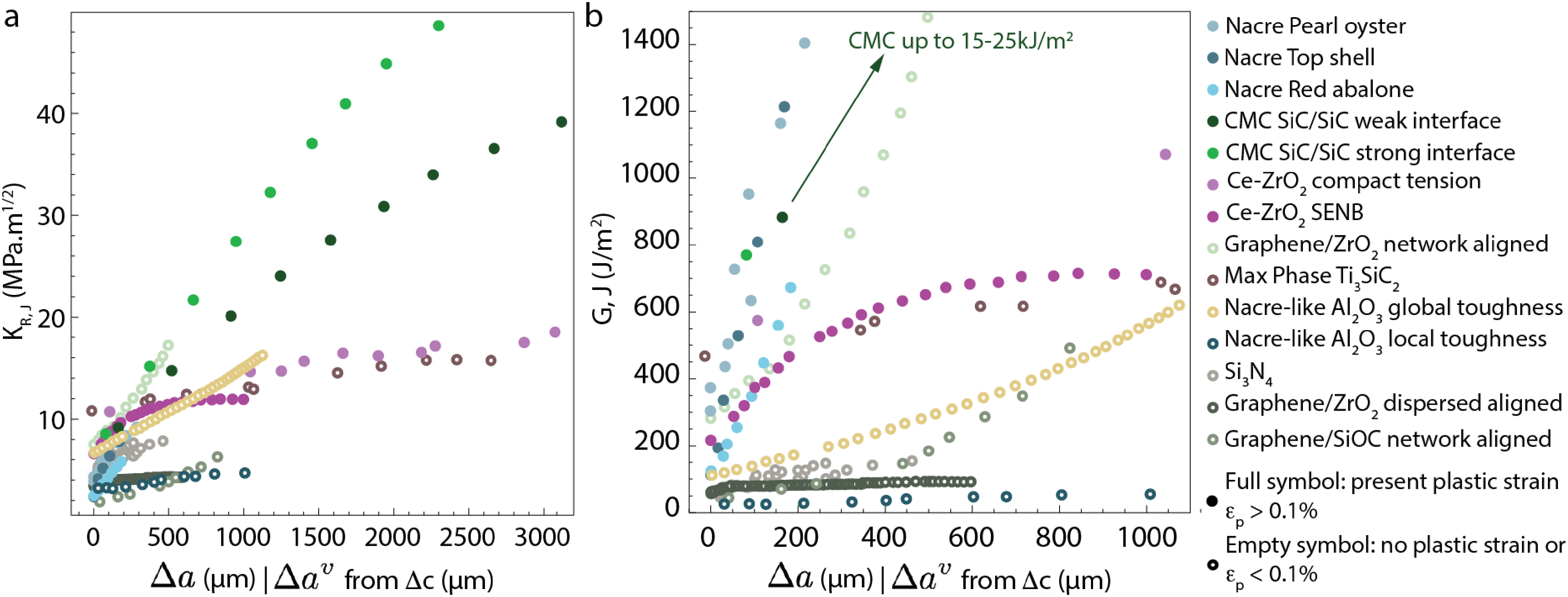
Comparison of tough ceramics R-curves and presence of plastic strain in tension. Data are the same as the other plots in the review for each material, with the relation
The final point and distinction that can be made by comparing all these materials, toughening mechanisms, and pseudo-ductile behaviour is the presence of reinforcement before the crack starts propagating or not. From the three compositions that present significant plastic deformation in tension, we can see that each relies on different toughening mechanisms, so there is not only one way to obtain a pseudo-ductile behaviour. The main difference in terms of behaviour for these three materials is that for both zirconia and nacre, the toughening mechanism takes place well before a crack propagates, with the initial growth of a frontal damage/transformation zone before the crack starts propagating. This, in turn, means that the R-curve values measured are different compared to all the other materials in this review, as the first irreversible damage happens before the first value given in the R-curve. In these two cases, the toughness increases from this first damage without the crack growing initially, similar to the way ductile materials plastify in front of the crack before any crack growth. Here, R-curves only tell part of the story, and it is hard to know how much this initial toughness increase contributes to the presence of the pseudo-ductile behaviour. The advance of small-scale testing in SEM and TEM will allow us to shed more light on the frontal damage zone in the early stages of crack propagation and its role in the stabilisation of the crack. What we can deduce by comparing with CMCs is that CMCs need a higher increase in toughness over a longer crack length to obtain a similar plastic strain level as nacre or zirconia, with CMCs toughness increasing 6-fold in over 4 mm while nacre increases 2.5-fold over 0.2 mm and zirconia increases 1.8-fold over 0.5 mm in terms of stress intensity factors. These ratios could change or even be similar if we were able to compare the final toughness with the ones at which damages first occur.
In summary, comparing all these ceramics and composites with increased toughness through a wide variety of toughening mechanisms, we can extract a few design principles that lead to pseudo-ductile behaviour. Regardless of the toughening mechanisms introduced in the structure, it becomes clear that materials with a high critical energy release rate rather than a high toughness are more susceptible to presenting a pseudo-ductile behaviour when tested in tension. Looking at the three compositions that present significant plastic strain, we can also deduce that either they produce a toughening mechanism that acts before the crack propagates and thus leads to a fast increase in toughness over a short crack propagation or the toughness is developed only after the crack starts and needs longer crack propagation and higher toughness values to be effective.
Conclusions
Tough structural materials are essential for applications ranging from construction, energy storage and generation, biomedical, and aerospace. Ceramics have a part to play in these applications, from their unique combinations of high temperature/corrosion resistance, bio-inertness, or long-term durability. While ceramics and their composites are still thought of as brittle in the general materials science field, there have been massive strides made in the last decades that can challenge this assumption. The design of microstructures and toughening mechanisms that can hinder crack propagation are at the core of these paradigm shifts. Ceramic processing is thus important for both the control it provides on the microstructure and the influence it has on the defect population and, finally, on the component reliability.
Because of that, crack propagation and toughness measurement were first reviewed here as multiple methods are used. There are experimental limitations to measuring fracture toughness accurately: the defect used as the starting point for the crack needs to be as sharp as possible; otherwise, the value measured can be overestimated by as much as a factor 2 and two methods can be used to track the crack length depending on its shape. When multiple cracks are present, compliance-based measurement can be used, but when there is only one crack that propagates in a relatively straight way, a direct crack tracking method is preferred.
Regarding the tough ceramics themselves, we first review the properties of ceramic matrix composites and recent developments in their characterisation and testing at a small length scale. SiC-based CMCs are some of the toughest ceramics made and present a pseudo-ductile behaviour in tension. The addition of small-scale testing allows the direct characterisation of the interface between fibre and matrix, which is critical for the toughening mechanisms and how it evolves in extreme environments.
We then discuss the recent advances made in zirconia-based materials, another ceramic that presents pseudo-ductile behaviour in tension due to its unique transformation toughening. The control of the phase transformation and grain size are key to providing both strong and ductile zirconia-based ceramics at room temperature, and the field is now looking at different doping strategies to reach this goal.
Finally, aside from these well-established tough ceramics, there are now multiple strategies available to shape tough bulk ceramics by introducing toughening mechanisms from the nano to the microscale. These strategies include randomly oriented elongated grains in silicon nitrides and carbides, the addition of graphene, the MAX phase that presents some degree of metallic bonding in their lattices, and finally, the use of natural materials blueprints to design different microstructures. While each strategy managed to introduce some degree of toughening, with the nacre-inspired alumina reaching a toughness value on par or higher than zirconia, none of these compositions showed plastic deformation when tested in tension. In the case of bioinspiration, the most used model is the one of nacre, and these natural materials present a yield strength and plastic strain behaviour in the same order of magnitude as CMCs while being made from weaker and more brittle materials. Thus, there is more to be learned from this approach before we can truly mimic this behaviour with any ceramic.
Putting all these materials and strategies together allowed us to make links between crack propagation, toughness values and the presence of plastic strain in tension. The presence of toughening mechanisms acting before the crack starts to propagate, as in zirconia and nacre, provides a similar plastic strain level as CMCs that rely on mechanisms developed over larger distances and volumes and reach higher toughness values. These are only initial conclusions from the data collected, and a quantitative link between toughness, reliability, and plastic strain magnitude is still an open scientific question.
As a final message, after summarising all these decades of advances in mitigating the main drawbacks of ceramics, what road and applications would open if there were simple ways to shape the microstructure of any ceramic to become tough enough to deform plastically? Ceramic materials are taking a central role in functional applications such as energy generation and storage, and increasing their toughness, regardless of their compositions, could have far-reaching implications for the durability and performance of these systems.
Footnotes
Acknowledgements
FB acknowledge support from the European Research Council Starting Grant [H2020-ERC-STG grant agreement n°948336] SSTEEL.
Declaration of conflicting interests
The authors declared no potential conflicts of interest with respect to the research, authorship, and/or publication of this article.
Funding
The authors disclosed receipt of the following financial support for the research, authorship, and/or publication of this article: This work was supported by the H2020 European Research Council, (grant number [H2020-ERC-STG grant agreement n°948336] SSTEEL).