
Abstract
Fused Filament Fabrication (FFF) is a highly sought-after manufacturing method that builds parts layer by layer using thermoplastic and/or composite filaments. However, it is characterised by weak interlayer adhesion, resulting in low interlaminar strength in printed structures. Recent research suggests that post-processing heat treatments can address this issue by lowering internal thermal stresses and increasing interlayer bonding, thereby improving part properties. This study investigates the effect of annealing heat treatment on a composite consisting of glycol-modified polyethylene terephthalate (PETG) and organically modified montmorillonite nanoclay (OMMT-NC). The annealing temperature was set at 90°C, and the time duration was varied to 60, 120, and 180 minutes. The mechanical, morphological and surface properties of the OMMT-NC reinforced PETG composite were compared with those of pure PETG. Also, annealing effect on the glass transition temperatures was determined by differential scanning calorimetry (DSC). Atomic Force Microscopy (AFM) was used to investigate the change in surface roughness resulting from annealing. The experimental results show that PETG reinforced with 3 wt.% OMMT nanoclay improved the tensile, compression, flexural, and impact strength by 6.9%, 22.9%, 30.3%, and 87.5%, respectively, after annealing. The hardness also increased across all PETG composites by at least 5%, due to improved interlayer adhesion. Morphological studies were conducted to correlate the deformation behaviour and assess the impact of annealing. The findings of this work indicate that PETG/OMMT-NC composites are a potential candidate for structural applications.
Keywords
Introduction
Additive Manufacturing (AM) is a layer-by-layer fabrication methodology that creates three-dimensional structures by controlling the fusion and deposition of materials, incorporating specialised processes, feedstock, and systems. 1 The American Society for Testing and Materials (ASTM) 2 categorises AM technologies into seven distinct process categories: vat photopolymerization, powder bed fusion, material extrusion, material jetting, sheet lamination, binder jetting, and directed energy deposition. 3 The consumer and prototyping industries are dominated by FFF, a subset of material extrusion, because of its cost-effectiveness and ease of use. 4 In FFF, a thermoplastic polymer filament is heated and extruded from a heated liquefier, then deposited onto a build platform through a precision nozzle. Each deposited layer fuses to the layer below it via thermal bonding. Although FFF has numerous benefits, including low startup costs, quick fabrication times, and compatibility with multi-material/multi-colour extrusion systems, 5 it still has several technical drawbacks. Suboptimal surface finish, limited selection of thermoplastic materials suitable for the process, and reduced mechanical properties are among the main disadvantages.6,7,8,9
Numerous studies have highlighted that to achieve superior mechanical properties in FFF components, printing parameters must be optimised. The structural integrity of printed parts is significantly influenced by critical process variables, including layer thickness, deposition width, raster orientation, and air gap (both intra- and inter-layer), as demonstrated by Mohamed et al. 4 To ensure their successful application in actual manufacturing settings, a comprehensive assessment is required, given the intricate interdependencies among these parameters 10 Wang et al. 11 found that reducing interlayer voids, porosity, and layer thickness improves tensile strength. The mechanical performance is compromised by thicker layers, which create larger air gaps. According to Kovan et al. 12 print orientation and layer thickness significantly affect interlayer bonding strength, with adhesion weakened by the raster spacing. Anitha et al. 13 found an inverse relationship between layer thickness and surface roughness, indicating that surface quality is also affected. According to Nancharaiah et al. 14 reducing air gaps and thinner layer thicknesses improves surface finish and interlayer cohesion by minimising void formation. Lower raster angles (e.g., 0°–30°) and wider raster widths maximise bending resistance, as shown by Gebisa et al. 15 Strength is increased by aligning rasters parallel to the loading direction because fractures must spread across several deposited strands rather than weak interlayer bonds. Due to their larger cross-sectional area and wider rasters, these components can support more weight, thereby reducing stress concentrations under mechanical loads. According to Ahn et al. 16 and Dawoud et al. 17 negative air gaps increase tensile strength by encouraging raster overlap, which improves part density and layer adhesion. While positive air gaps lead to poor interfacial bonding due to insufficient contact between adjacent rasters, excessive negative gaps risk material accumulation on the nozzle or part surface.
Studies have shown that post-process annealing plays a significant role in enhancing the mechanical performance of printed parts, even beyond the printing parameters. 18 Thermal annealing, also known as heat treatment, is a common post-processing method used to improve the strength of FFF components. This technique is especially effective for modifying the molecular structure of polymers and polymer composites, thereby enhancing the material’s properties. Annealing improves mechanical strength, thermal and electrical conductivity, and viscoelastic behaviour by increasing polymer crystallinity.19–22 However, the polymer’s glass transition temperature (Tg) affects its response to thermal cycles. 23 Rapid cooling of extruded filaments in FFF usually produces low-crystallinity or amorphous structures. To encourage polymer crystallinity and crosslinking and, eventually, improve the part’s overall performance, post-printing annealing is crucial. 24 Strength, impact resistance, thermal stability, and electrical performance are among the mechanical and thermal attributes that improve when polymers are annealed at temperatures higher than their Tg, as this process increases crystallinity.25,26,27 For example, Hong et al. 28 found that polylactic acid (PLA) improved its compressive strength by 39.8% and its bending strength by 58.3% after being annealed at 130°C for 300 seconds and 140°C for 600 seconds. The stronger interfacial bonding resulting from heat treatment was credited with these improvements. Similarly, annealed polyethylene terephthalate glycol (PETG) exhibited significant improvements in hardness, tensile strength, impact strength, and bending strength, increasing by 7.8%, 8.5%, 5.5%, and 9.4%, respectively, as reported by Kumar et al. 29 The improvements were much more noticeable when carbon fibre-reinforced PETG had the same treatment; the corresponding improvements were 14.8%, 22%, 12.1%, and 10.5%. Increased interlayer diffusion bonding was associated with these benefits. According to El Magri et al. 30 annealing at slow heating and cooling rates significantly increases crystallinity, thereby enhancing Young’s modulus and tensile strength. This impact results from the removal of structural flaws and the reduction of residual stresses. The significant impact of post-process annealing has been further underscored by recent investigations of FFF-printed PETG composites. Studies on carbon fibre-reinforced PETG (CFPETG) have shown that annealing improves both tribological and mechanical properties; results depend on variables such as infill density and annealing time. Additionally, studies on infill patterns have demonstrated that certain geometric deposition techniques in conjunction with heat treatment can optimise the mechanical behaviour of both PETG and CFPETG. These results highlight the crucial role of annealing as a post-processing step30–34. Barkhad et al. 35 examined compression-moulded PLA in another work and discovered that annealing enhanced the material’s modulus and compressive strength by 73% and 84%, respectively. The development of distinct crystals and spherulites during heat treatment, which improved inter-bead bonding and crystallinity, was credited by the authors for these enhancements.
However, annealing can cause dimensional changes. D'Amico et al. 36 reported that items printed with FFF may expand perpendicular to the printed layers or distort when annealed above the glass transition temperature due to the alleviation of residual stress. Wang et al. 37 and Kantaros and Karalekas 38 provided additional evidence for this discovery, noting that FFF-printed components retain internal tensions that are released during annealing, frequently resulting in deformation as the material relaxes. According to research by Arjun et al. 39 two methods for improving the mechanical properties of 3D-printed parts are process parameter optimisation and annealing treatments. These techniques can greatly enhance overall performance when combined. However, according to Valvez et al. 40 annealing may degrade the dimensional and geometric accuracy of printed components, potentially limiting their use in structural applications. To gain a more thorough understanding of how FFF parts can be optimised, Patel et al. 41 recommended further research on various materials and mechanical properties, which, along with these findings, highlighted both the benefits and drawbacks.
The addition of nanoscale fillers to PETG can improve the mechanical, thermal, and barrier properties of FFF-printed parts. In particular, when the high-aspect-ratio silicate layers in OMMT-NC are properly intercalated and exfoliated within the polymer matrix, they form a twisted network that enhances gas barrier performance and acts as a strengthening agent, making the material stiffer and more stable at high temperatures.42,43 Achieving and maintaining a well-dispersed nanostructure is essential for the significance of these advancements. The research on polymer-clay nanocomposites has demonstrated that there is an ideal loading range where property improvements are maximised, usually between 1 and 5 wt.%. 44 Effective clay platelet dispersion is most likely to occur within this low-concentration range; exceeding it often leads to agglomeration, which can impair material performance. PETG-specific studies provide proof of this concept; for example, tests on PETG composites have shown that OMMT-NC loadings of 1 and 3 wt.% can increase stiffness and wear resistance without causing significant agglomeration. 45
From the literature review, the authors found, to the best of their knowledge, that research on the annealing effects on PETG composites is scarce. Therefore, in this study, PETG-reinforced OMMT-NC polymer composites were FFF-printed and investigated for the effects of annealing on their mechanical, glass transition temperature and microstructural properties. Furthermore, atomic force microscopy was employed to evaluate the changes in surface properties of PETG composites under various annealing conditions. The findings presented in this work will be instrumental in designing FFF-printed lightweight sustainable structures.
Materials and methods
Materials
Compositional data of the composites.

Processing of materials
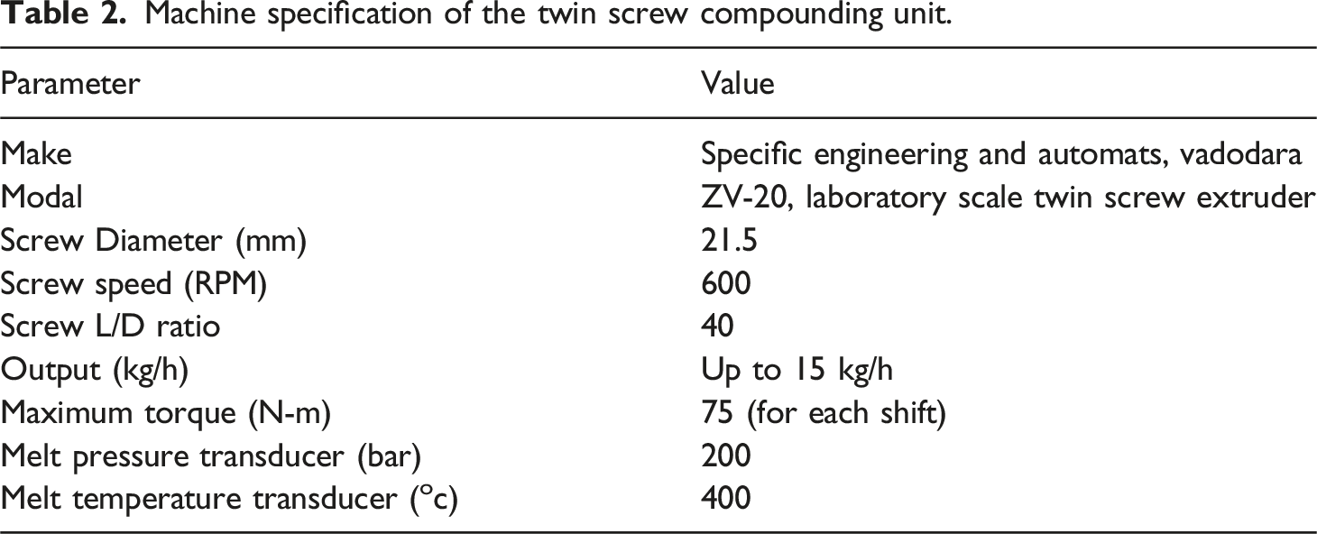
Machine specification of the twin screw compounding unit.
FFF printing of PETG/OMMT-NC specimens
Using the Schematics of the (a) the FDM process specifications and values.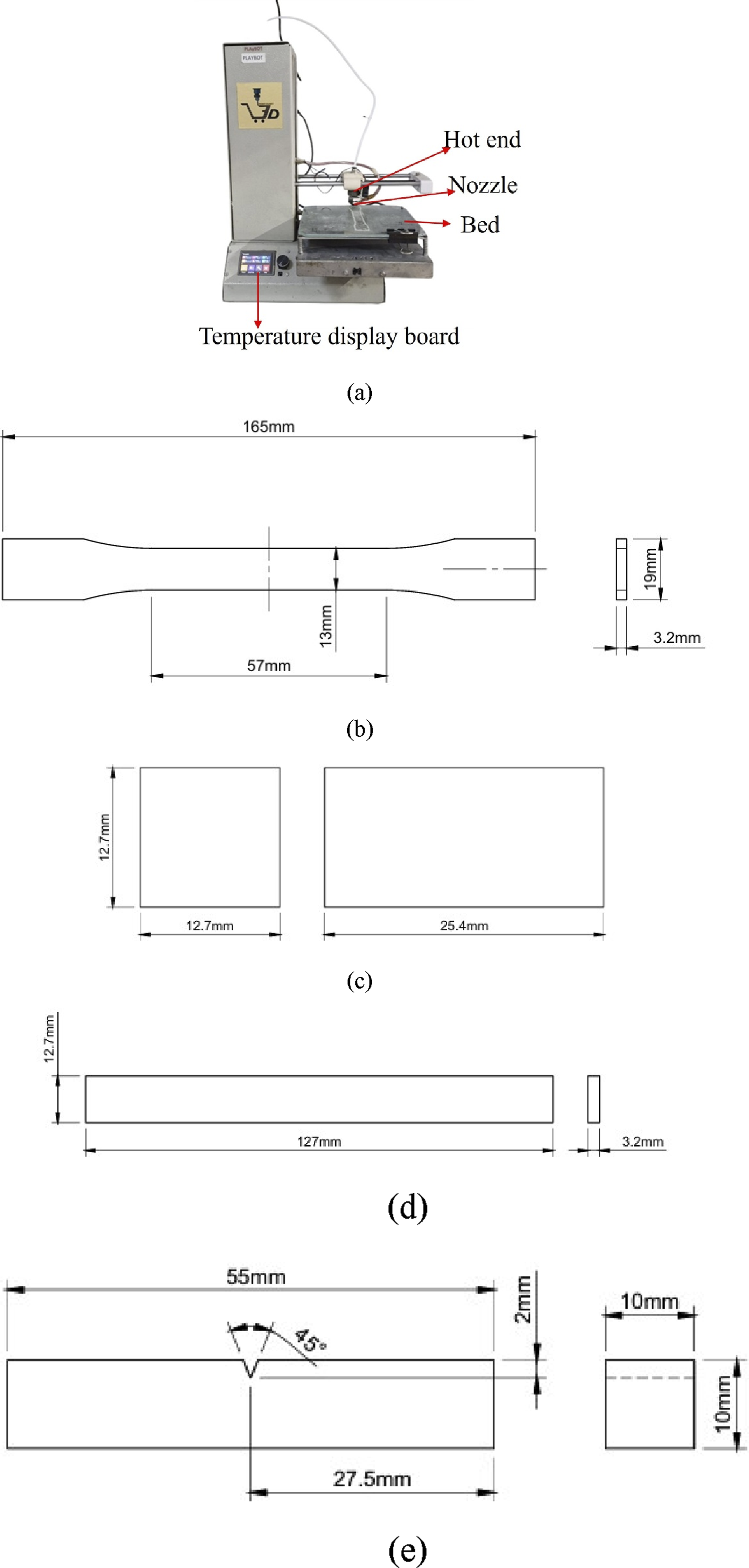
Isothermal annealing
To assess the influence of annealing on mechanical properties, the 3D-printed PETG/OMMT-NC composite specimens were heated from room temperature to the target annealing temperature of 90°C at 5°C/min for 1, 2, and 3 hours. Due to the amorphous nature of PETG, at 90°C the polymer chains are mobilised beyond the glass transition temperature (∼80°C). However, it is still well within the limits to avoid excessive material deformation caused by thermal instability. Further, the printed samples are placed in a hot air convection oven to minimise differential shrinkage and internal stresses.
Differential scanning calorimetry (DSC)
To investigate the influence of annealing on the glass transition temperature (Tg) of the FFF-printed PETG/OMMT-NC composite specimens, DSC analysis (Q2000, TA instruments, USA) was carried out in an N2 environment from 40°C to 100°C at a rate of 10°C min−1, with one heating cycle. Samples of about 5 mg were taken from the FFF-printed specimens.
Tensile, compression and flexural tests
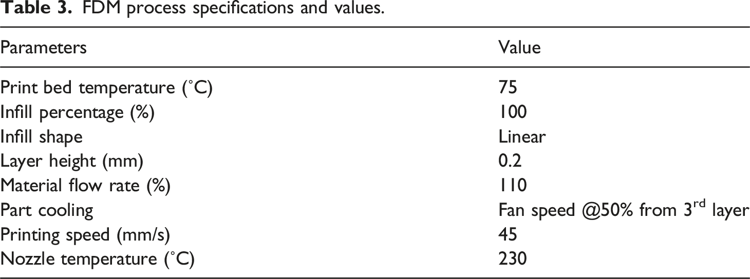
The tensile, compressive, and flexural characteristics of the annealed PETG/OMMT-NC composites were evaluated using a UTM (Mecmesin, PPT Group UK Ltd) with a maximum capacity of 50 kN. A calibrated 10 kN load cell is used to accurately measure the load. A steady strain rate of 5 mm/min was used for each test. Tensile, compression, and three-point bending tests were used to study. The UTM and extensometer were controlled by a computer to ensure accurate, easy-to-manage testing and reliable data. The experimental setup for tensile, compressive, and flexural testing, respectively, is shown in Figure 2 (a)–(c). Experimental setup for (a) tensile, (b) compression, (c) flexural test, (d) hardness tests.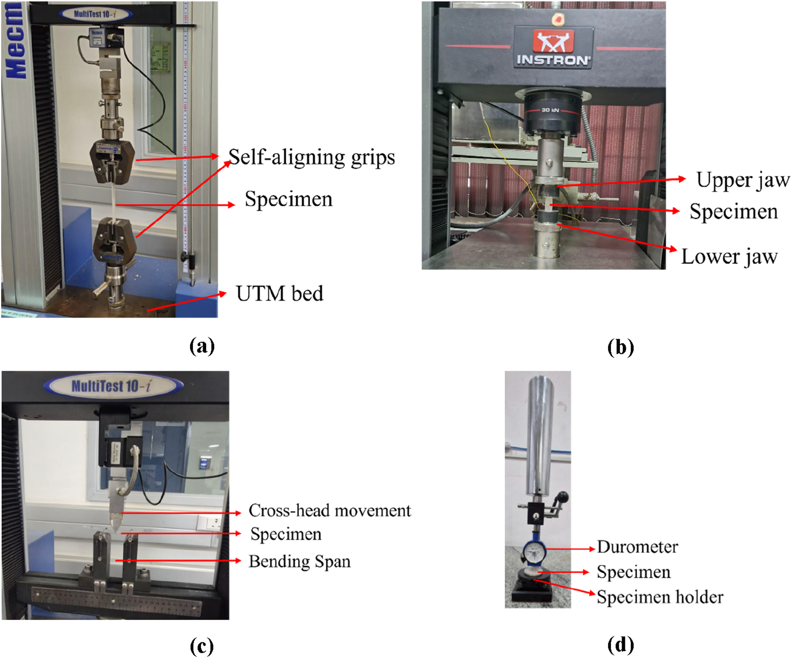
Izod impact test
The impact strength of the PETG/OMMT-NC composites was assessed using the Izod impact test. The Izod impact machine, manufactured by International Equipment, India, having a 0.1–25 J range, was used for testing. The impact is produced utilising a farming hammer measuring 13.3 × 13.3 × 21 mm, with a striking edge thickness and radius of 1.9 mm and 0.8 mm, respectively. The readings were digitally recorded by a computer directly connected to the machine.
Hardness test
Following ASTM D2240, the hardness of the FFF printed PETG/OMMT-NC composites was evaluated using the ‘D' scale of a Shore-D hardness tester from Yuzuki, India. Flat FFF-printed bars were fabricated using consistent printing parameters, matching those employed in previous tests. Hardness measurements were taken at five different points on the specimen’s flat surface, and the mean value was calculated to ensure accuracy. The experimental setup for hardness testing is shown in Figure 2(d).
Scanning electron microscope (SEM) characterization
To identify the most likely reasons for composite failure, the fracture surfaces of the tensile specimens were examined using an SEM (FEI ESEM Quanta 200). All the specimens were gold sputtered to improve surface conductivity and produce high-quality images. The specimens were examined in the low-energy secondary electron mode at a fixed accelerating voltage of 10 kV. The bonding issues and other potential failure mechanisms of the fracture surfaces were carefully inspected.
Surface roughness test
The effect of annealing on the surface morphology of FFF-printed PETG/OMMT-NC composite samples was investigated using AFM. For brevity, only samples annealed for 3 h were considered. The measurements were done using a Bruker atomic force microscope in ambient air. Contact mode experiments with a constant amplitude were conducted using microfabricated cantilevers. Further, scanning was performed using a SCOUT 70 RAI contact mode with an aluminium reflective backside coating in the form of a conical tip. The cantilever probe had a length of 125 µm and a tip height of 12 µm. The nominal tip radius of curvature was less than 10 nm, and the force constant (K) was 42 N/m. This study focused on images with a surface area of 30 × 30 µm2. The images were analysed using Nasoscope Imaging Processing software.
Results and discussion
Differential scanning calorimetry (DSC)
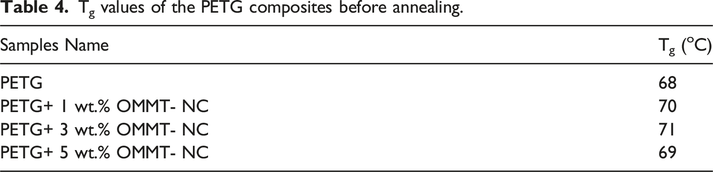
Tg values of the PETG composites before annealing.
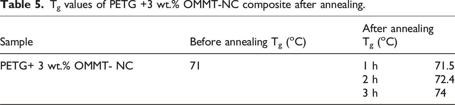
Tg values of PETG +3 wt.% OMMT-NC composite after annealing.
Mechanical characterisation
Tensile test
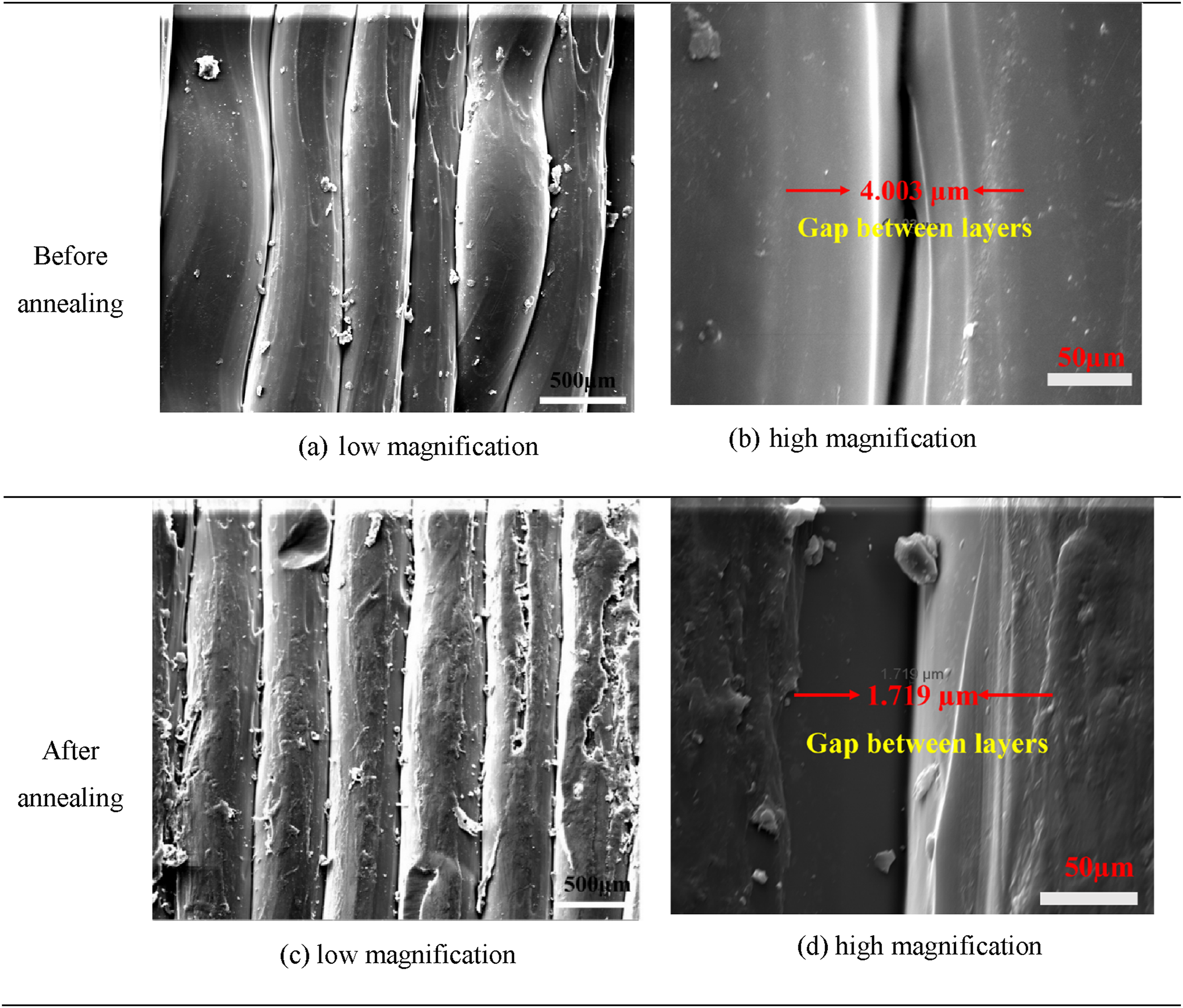
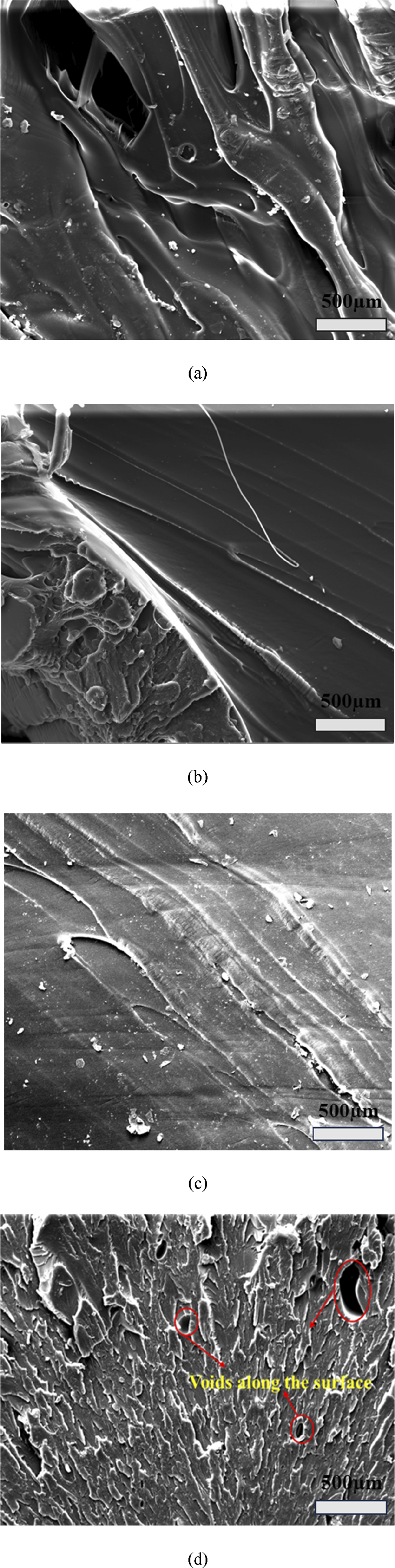
In this section, the tensile characteristics of annealed and unannealed PETG/OMMT-NC composites have been investigated. Figure 3(a) and (b) compare the stress-strain curves of unannealed and annealed PETG composites, respectively. Table 6 compares the strength and tensile modulus of various PETG/OMMT-NC composites considered in this study. Figure 4 illustrates the interlayer bonding of PETG + 3 wt.% OMMT-NC composites, for annealed and unannealed states. Figures 5 and 6 depict the fractured specimens and SEM imaging of the fractured surfaces of PETG/OMMT-NC composites, respectively. Tensile stress–strain curve of different PETG composites (a) before annealing, (b) after annealing. Tensile properties of the PETG/OMMT-NC composites. SEM images of variation in the interlayer bonding of PETG +3 wt.% OMMT-NC before and after annealing. Tensile fractured PETG/OMMT-NC composite specimens. SEM images of the fracture site of tensile tested annealed (a) PETG, (b) PETG +1 wt.% OMMT-NC, (c) PETG +3 wt.% OMMT-NC (d) PETG +5 wt.% OMMT-NC samples.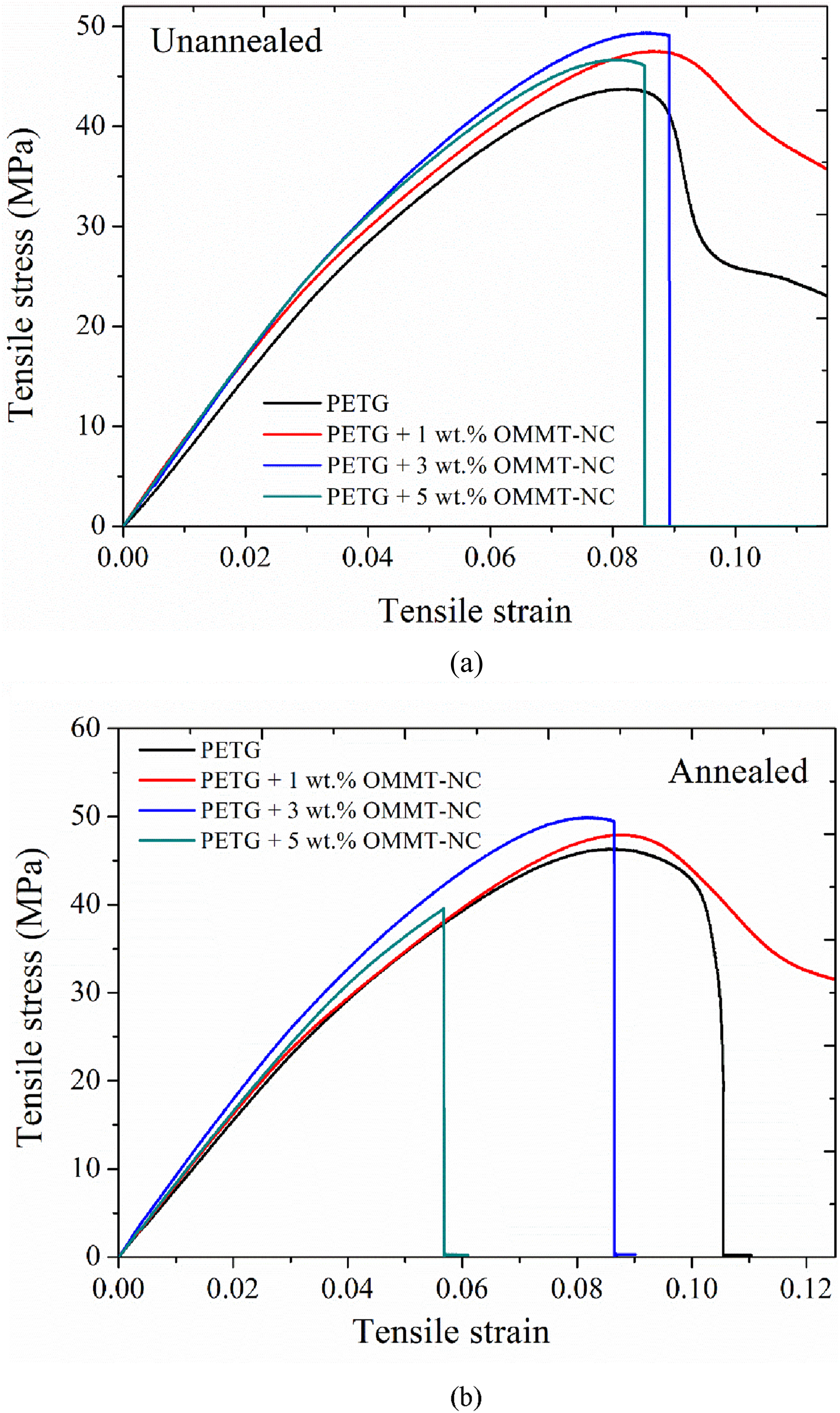
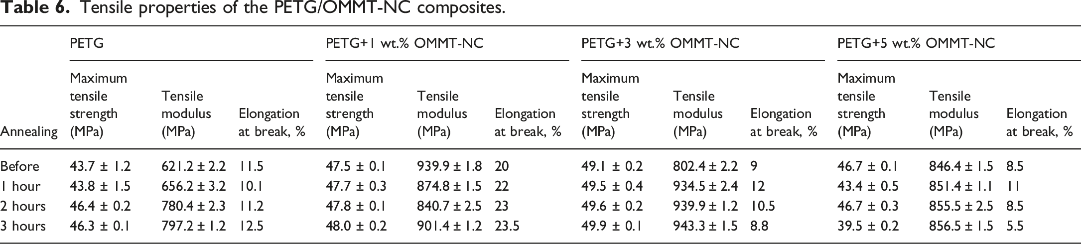
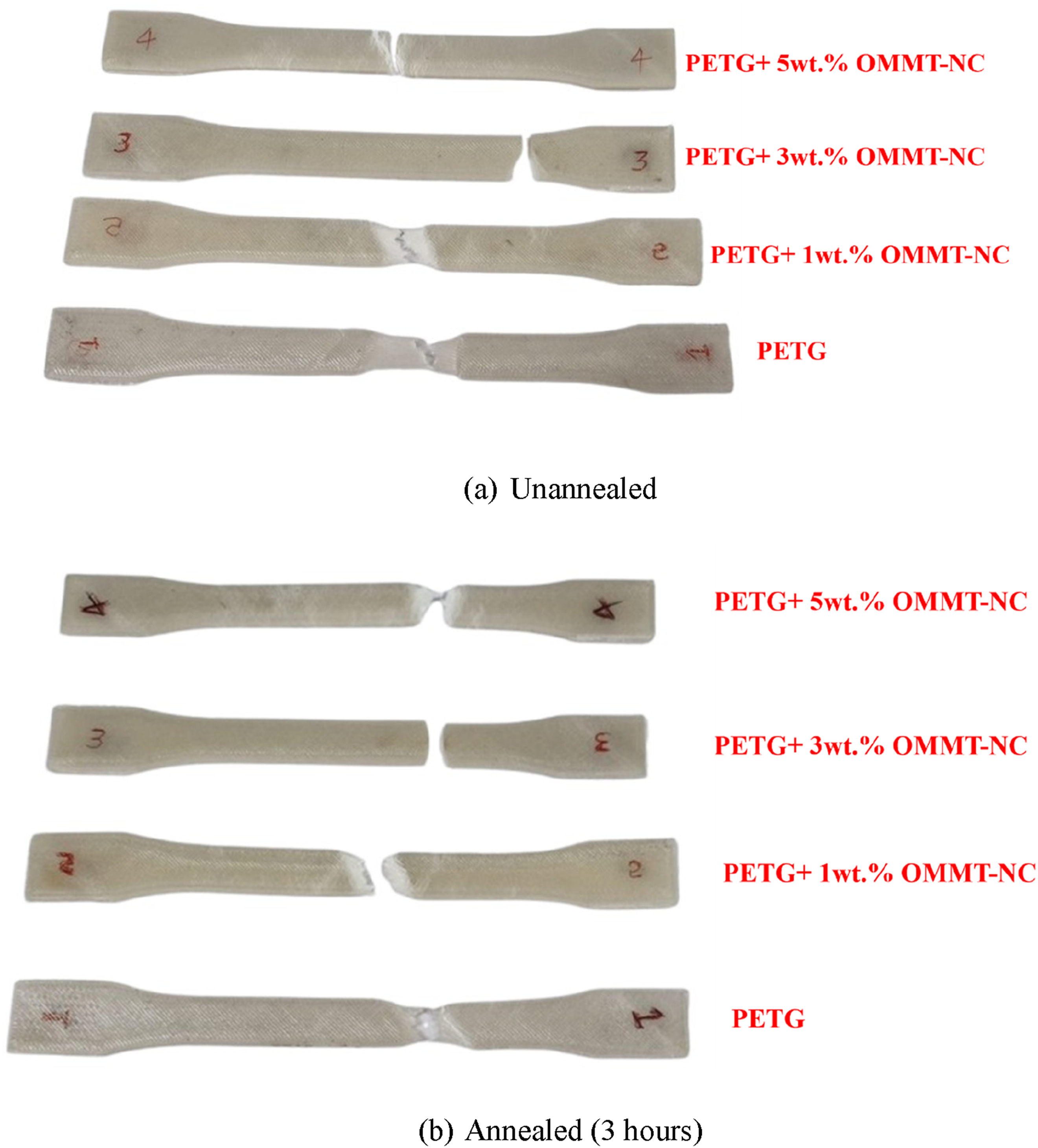
As shown in Figure 3(a), inclusion of 3 wt.%. OMMT-NC had a greater effect on tensile strength, attributed to enhanced bonding between OMMT-NC and the PETG matrix (Figure 4). The tensile strength increased by 9%, 12%, and 7% for PETG +1 wt.% OMMT-NC, PETG +3 wt.% OMMT-NC, and PETG +5 wt.% OMMT-NC, respectively, while the tensile modulus improved by 51%, 29%, and 36.23% when compared to virgin PETG and for similar post-processing of 3D-printed parts that have been described. 39 Further, it can be clearly seen that virgin PETG and PETG +1 wt.% OMMT-NC exhibits a ductile behaviour. However, at OMMT concentrations above 1 wt.%, a transition from ductile to brittle behaviour was observed. The tested specimens depicted in Figure 5 also confirm the same. From Table (6), it is evident that PETG +1 wt.% OMMT-NC exhibits a greater elongation at break, suggesting that better ductility can be attained at an optimum OMMT-NC wt.% of 1, beyond which the composites become brittle. Among the different OMMT-NC composite variants considered, the addition of 5 wt.% OMMT-NC yielded a lesser tensile strength as opposed to 1 wt.% and 3 wt.% OMMT-NC addition, owing to the higher void creation, which might be due to enhanced filler-filler interactions and agglomerate formation, as illustrated in (Figure 6(d)).
The effect of annealing on the tensile behaviour of the considered PETG/OMMT-NC composites is shown in Figure 3(b) and also tabulated in Table 6. From Figure 3(b), it is evident that annealing significantly improves the tensile properties. These improvements were due to enhanced interlayer bonding facilitated by annealing. The SEM images (Figure 4) confirmed the reduction in interlayer gaps from 4.003 µm (before annealing) to 1.719 µm (after annealing), indicating a significant enhancement in interlayer adhesion and bonding. It is to be noted that, though the tensile properties have been slightly improved after annealing, the mechanical behaviour (tensile or brittle) originally displayed by the PETG/OMMT-NC composites remains unchanged. After annealing, the virgin PETG and PETG +1 wt.% OMMT-NC, which originally exhibited a ductile behaviour, showed an enhanced ductile behaviour, which is reflected via a greater magnitude of elongation at yield. Likewise, PETG +3 wt.% OMMT-NC and PETG +5 wt.% OMMT-NC composites exhibited a higher degree of brittleness, as could be seen by reduced elongation at yield, from Table 6.
The SEM fractography in Figure 6(a)–(d) indicates a transition from ductile to highly brittle fracture, consistent with the obtained mechanical response. Figure 7(a) exhibits shear-dominated ductile fracture in virgin PETG, characterised by tearing ridges and plastic flow features, indicating ductility with localised deformation prior to failure. The SEM image of PETG +1 wt.% OMMT-NC (Figure 6(b)) shows pronounced microvoid coalescence with large void clusters and a rough, highly deformed fracture surface, indicating enhanced plastic deformation and improved ductility compared to virgin PETG. Meanwhile, Figure 6(c) reveals cleavage-dominated brittle fracture, with relatively flat facets and directional crack propagation, indicating a brittle fracture appearance of PETG +3 wt.% OMMT-NC composite. However, the improved mechanical performance of PETG +3 wt.% OMMT-NC composites suggest that crack deflection, pinning, and other energy-dissipating mechanisms are active prior to final fracture. For PETG +5 wt.% OMMT-NC, Figure 6(d) displays a faceted fracture morphology with angular, step-like features, indicating negligible plastic deformation and highly brittle behaviour. Schematics of the (a) compressive stress–strain curves before annealing (b) compressive stress–strain curves after annealing, (c) before and after compression tested samples.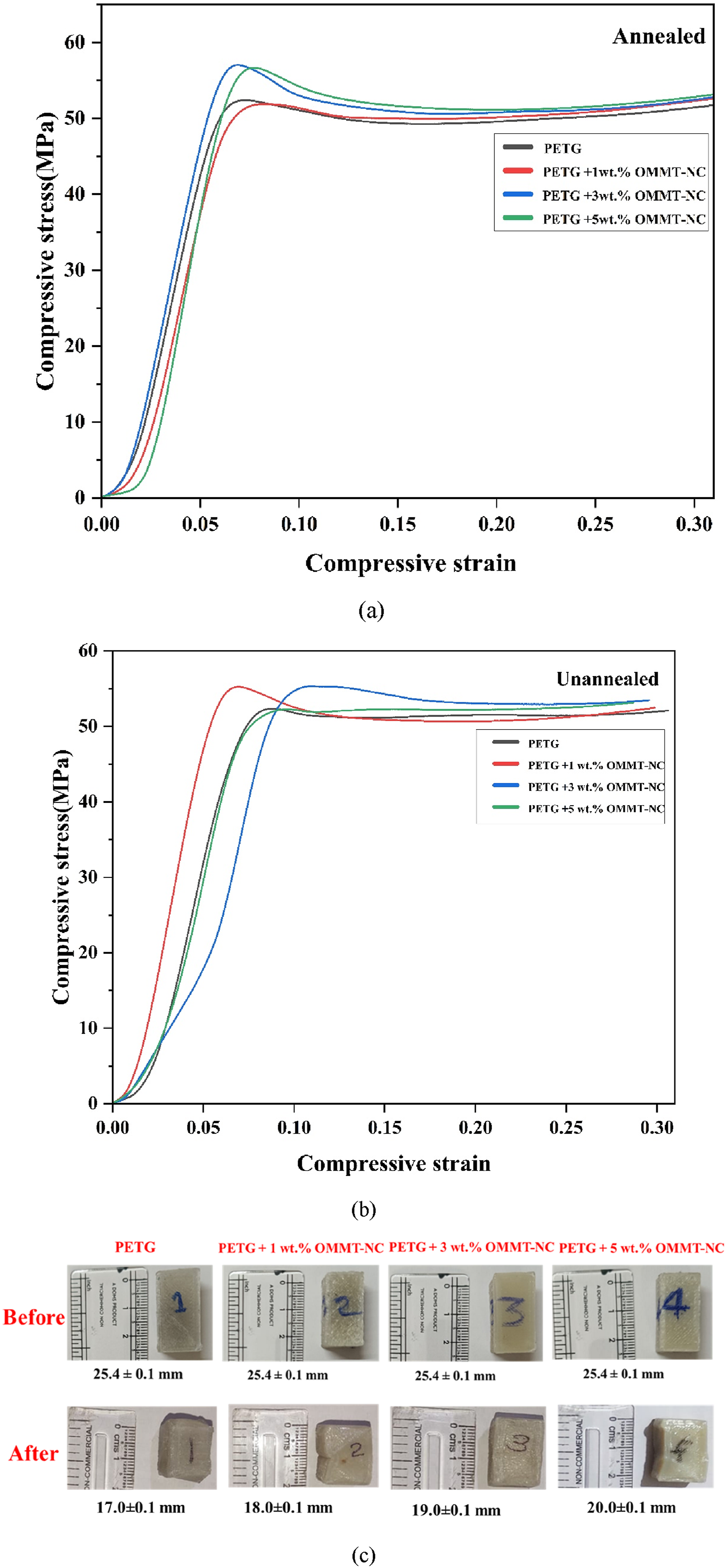
Compression test
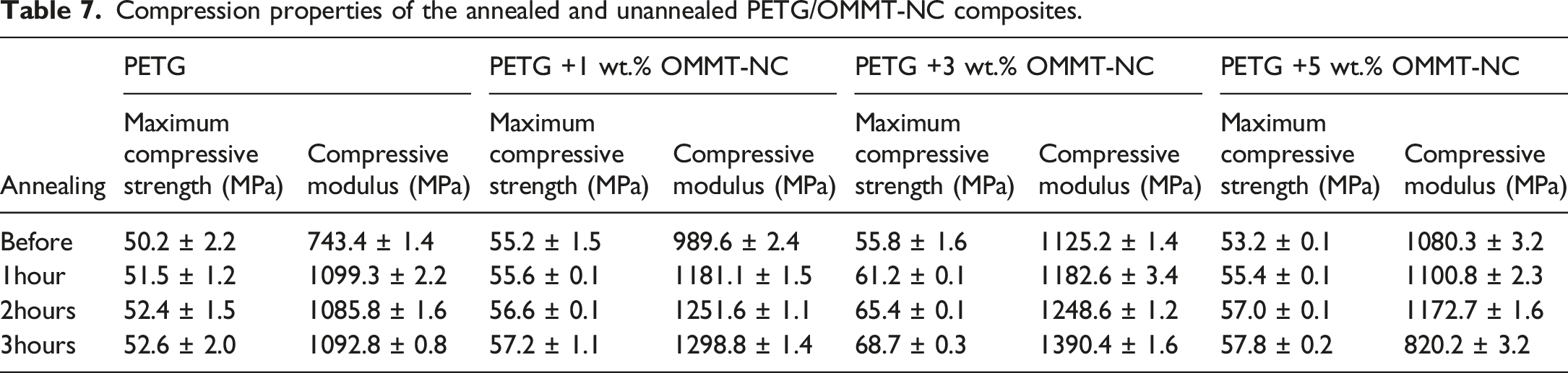
Compression properties of the annealed and unannealed PETG/OMMT-NC composites.
Flexural test
Figure 9(a) shows that the flexural performance improves with nanoclay loading up to 3 wt.% OMMT-NC, followed by a decline at 5 wt.% OMMT-NC, relative to neat PETG. Specifically, the flexural strength increases by about 20.3% for the 1 wt.% and by about 22.8% for the 3 wt.% OMMT-NC formulations compared with pure PETG. However, due to particle agglomeration and the presence of stress concentrators that promote fracture initiation under bending, the 5 wt.% shows a decrease in both flexural strength and modulus.
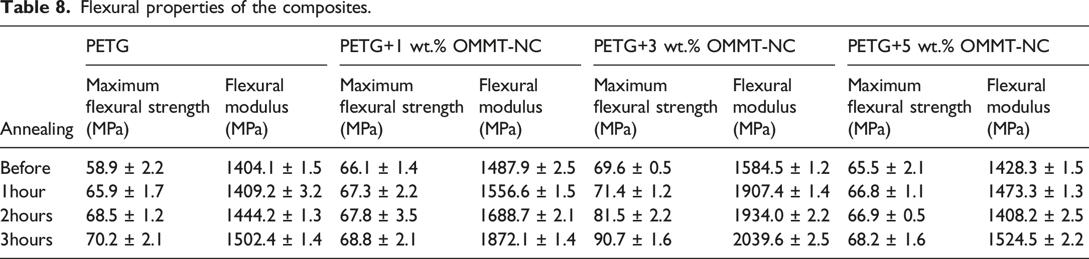
Annealing effects (Figure 8b) further augment flexural properties across all compositions. After 3 hours of annealing, the flexural strength of neat PETG rises by approximately 19.1%, while the PETG/OMMT-NC composites with 1 wt.% and 3 wt.% show larger gains of about 30.3% and 30.0%, respectively. This improvement suggests that annealing causes partial crystallisation and a reduction in internal stresses, both of which enhance load transfer and bending resistance.42,48,49 The 3 wt.% formulation exhibits the greatest improvement, with a flexural modulus increase of over 28.7% to approximately 2039 MPa (Table 8). Figure 8c shows the before-and-after annealing test samples. Schematics of the (a) flexural stress–strain curves before annealing (b) flexural stress–strain curves after annealing, (c) before and after flexural tested samples. Flexural properties of the composites.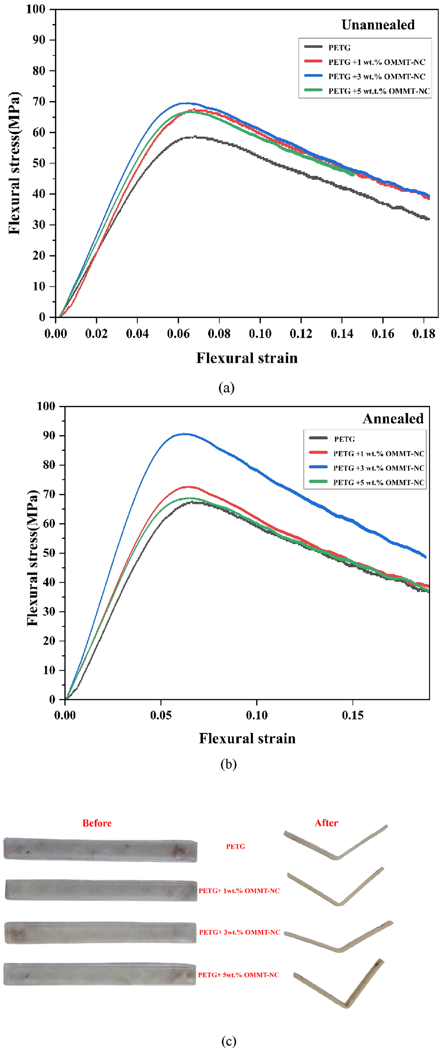
Impact test
Impact strength (in kJ/m2) of the PETG/OMMT-NC composites before and after annealing.
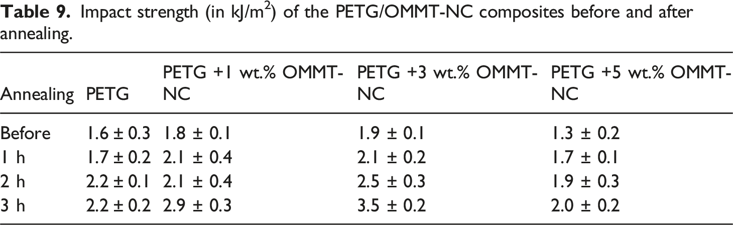
The data also show a notable increase in impact strength after annealing the PETG composites. For each sample, impact strength increased progressively with longer annealing times. According to the percentage increase in impact strength after 3 hours of annealing (PETG: 38%, PETG +1 wt.% OMMT-NC: 58.3%, PETG +3 wt.% OMMT-NC: 87.5%, PETG +5 wt.% OMMT-NC: 113%), the annealing process greatly increases the material’s impact strength because it relieves residual stresses caused by processing and advances physical ageing, which causes structural relaxation and mobilisation of polymer chains, allowing them to relax into a lower-energy, more thermodynamically stable state. This method minimises stress concentrators while increasing the material’s density, thereby requiring more energy for crack formation and propagation.42,49,50
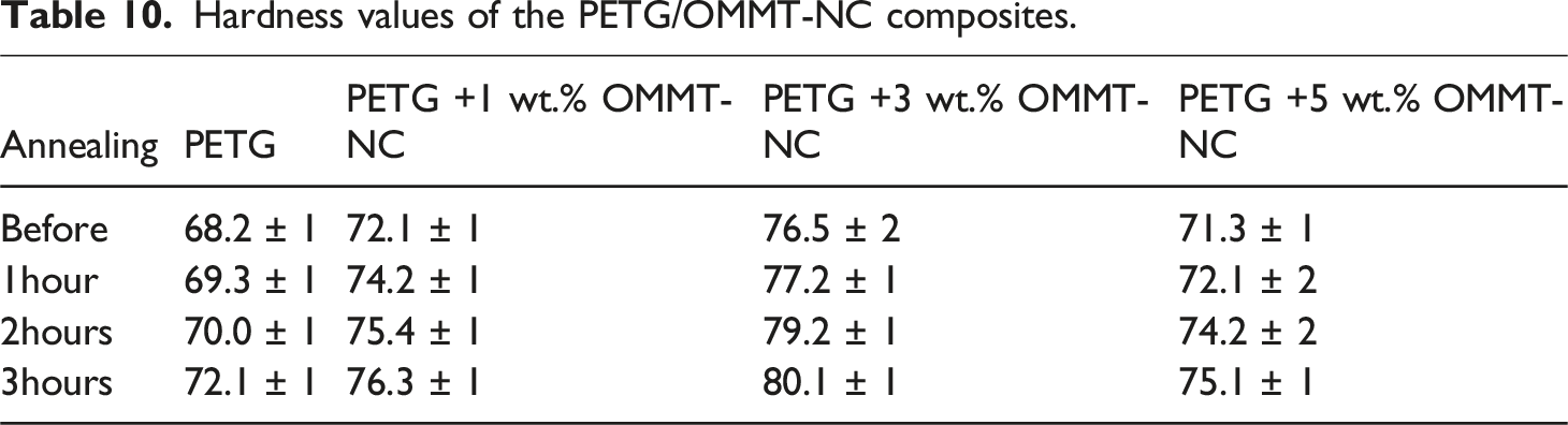
Hardness test
Hardness values of the PETG/OMMT-NC composites.
AFM analysis
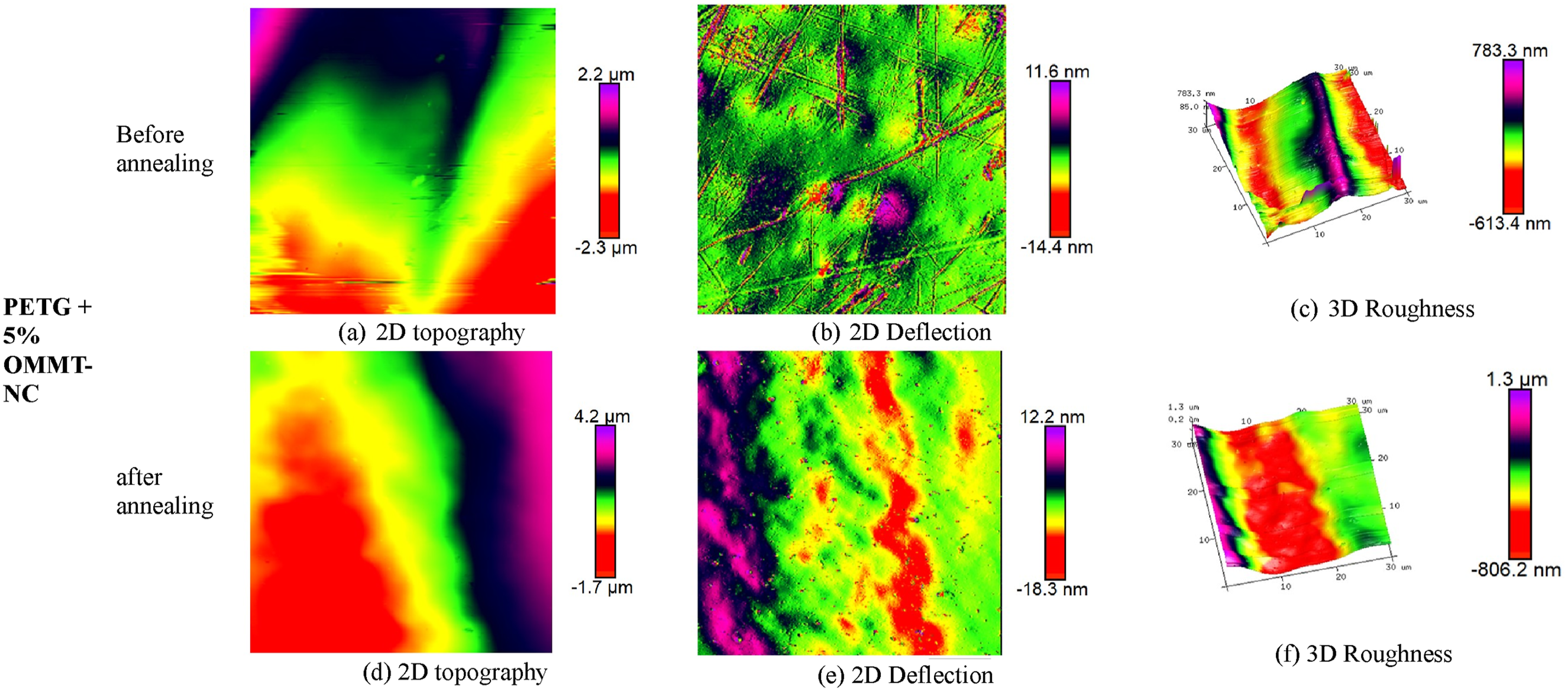
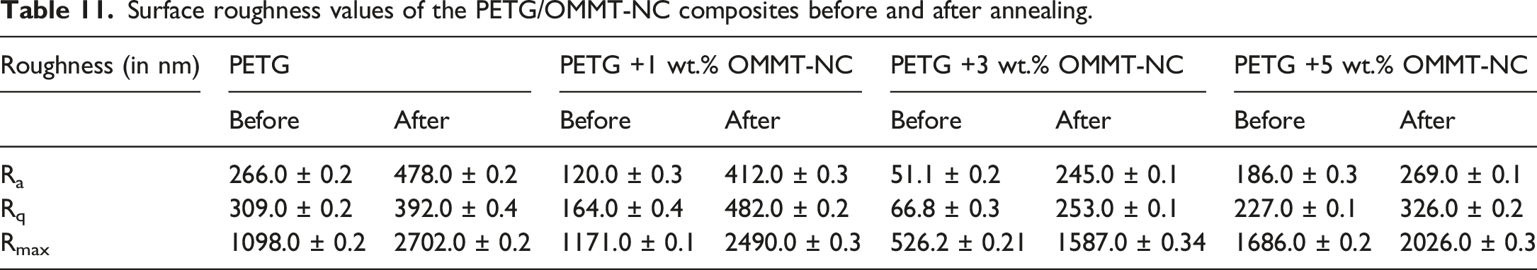
Figures 9–12 illustrate the surface roughness of PETG/OMMT-NC composites both before and after 3 hours of annealing at 90°C. Also, the values of average roughness (Ra), root mean square (Rq), and maximum roughness (Rmax) are summarized in Table 11. Before annealing, the PETG sample exhibited a smooth and relatively flat surface (Figure 9(c)) with Ra, Rq, and Rmax values of 266.23 nm, 309.2 nm, and 1098.22 nm, respectively (Table 11). In comparison, after annealing, the AFM images of the pure PETG surface (Figure 9(f)) show increases in Ra, Rq, and Rmax to 478.2 nm, 392.4 nm, and 2702.2 nm, respectively. The AFM images show that the surface transitions from fairly flat to more rugged, with larger peaks and smaller valleys. This is because, above the glass transition temperature, the polymer chains acquire sufficient mobility to reorganise, resulting in the formation of peaks and valleys upon cooling.
51
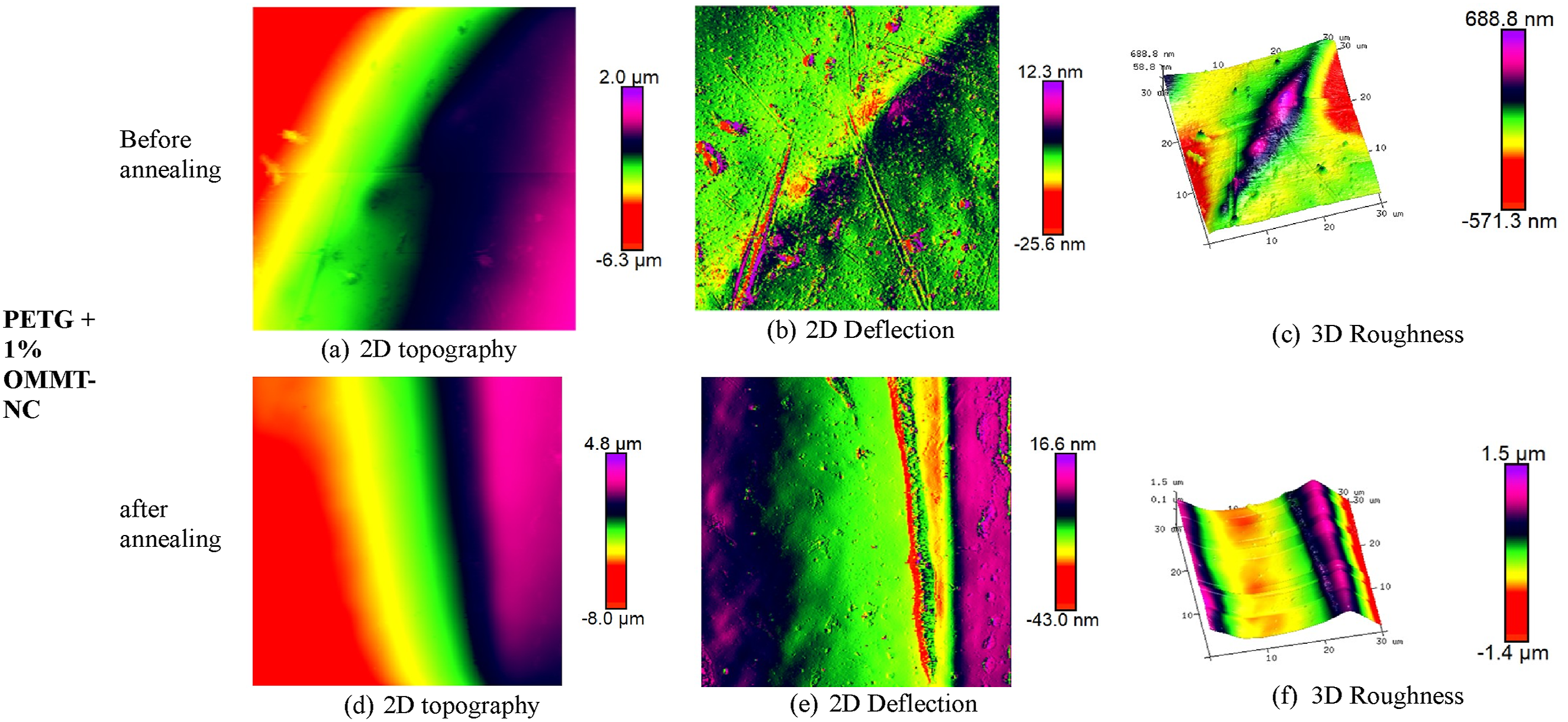
Among all the PETG/OMMT-NC composites, the PETG +3 wt.% OMMT-NC sample showed the lowest roughness before annealing, with Ra, Rq, and Rmax values of 51.1 nm, 66.8 nm, and 526.2 nm, respectively. The smooth surface is attributed to the well-dispersed nanoclay particles, which act as fixed barriers that limit the movement of polymer chains during shaping and cooling. This prevents the formation of large peaks and valleys on the surface. As a result, the most uneven surface was observed in the heated-and-cooled PETG, indicating that OMMT-NC is an effective stabiliser. It helps stabilise the polymer’s shape when heated by preventing large-scale chain movements. Additionally, 2D surface deflection images shown in Figures 9–12 (b) and (e) correlate with the surface roughness values obtained in Table 11. Surface roughness of PETG obtained via AFM. Surface roughness of PETG +1 wt.% OMMT-NC composites obtained via AFM. Surface roughness of PETG +3 wt.% OMMT-NC composites obtained via AFM. Surface roughness of PETG +5 wt.% OMMT-NC composites obtained via AFM. Surface roughness values of the PETG/OMMT-NC composites before and after annealing.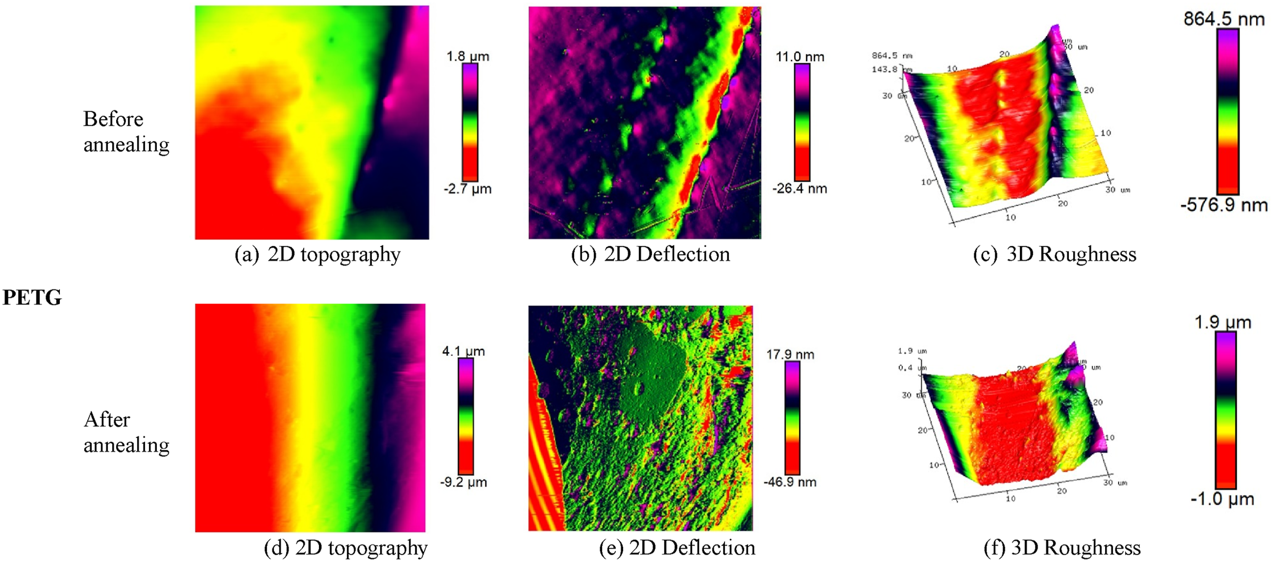
Conclusions
This research investigates the effects of annealing and OMMT-NC addition on the mechanical, morphological and surface properties of FFF-printed PETG/OMMT-NC composites. From the experimentation, it was revealed that the incorporation of 3 wt.% OMMT-NC improved tensile, compressive, flexural, and impact strengths by up to 13%, 11%, 18%, and 18%, respectively, along with a 5% increase in hardness, attributed to its effective exfoliation and intercalation. This facilitates stress transfer from the PETG matrix to the rigid OMMT-NC, thereby constraining polymer chain mobility and enhancing stiffness without considerable agglomeration. Conversely, adding 5 wt.% OMMT-NC resulted in adverse effects on mechanical properties due to nanoclay agglomeration, which generates stress concentration points and compromises interfacial bonding. Meanwhile, higher OMMT-NC concentrations (3 and 5 wt.%) were found to make the PETG matrix brittle.
Meanwhile, annealing further enhanced these improvements across all compositions, with mechanical properties correlating with treatment duration. The maximum improvements were 8% in tensile strength, 23% in compressive strength, 29% in flexural strength, and 84% in impact strength. This is due to enhanced interlayer bonding induced by annealing, as confirmed by morphological studies. Although the PETG +3 wt.% OMMT-NC composite exhibited brittle behaviour, its superior impact energy absorption could be attributed to the uniformly distributed nanofillers, which promote crack deflection, pinning, and branching, increasing the crack propagation path and requiring additional energy for fracture. Meanwhile, the AFM results confirmed that surface roughness in PETG composites changed markedly after annealing. PETG +3 wt.%. OMMT-NC showed minimal surface alterations after annealing across the various composites. The combination of OMMT-NC reinforcement and annealing significantly enhanced the mechanical performance, energy absorption, and surface properties of PETG composites. It is believed that the results of this work would pave the way for further research on PETG composites for structural applications.
Footnotes
Acknowledgements
The financial support of the Department of Science and Technology (DST) through the Scheme for Young Scientists and Technologists (SP/YO/2021/1652) is sincerely acknowledged by the author, Vinyas Mahesh. The authors, Prashanthkumar Hadi, Dineshkumar Harursampath, and Vishwas Mahesh, acknowledge the financial support of the Department of Science and Technology (DST) and the Science and Engineering Research Board (SERB) through the Core Research Grant (CRG/2023/000083).
Declaration of conflicting interests
The authors declared no potential conflicts of interest with respect to the research, authorship, and/or publication of this article.
Funding
The authors disclosed receipt of the following financial support for the research, authorship, and/or publication of this article: This study was supported by Department of Science and Technology (DST) through the Scheme for Young Scientists and Technologists (SP/YO/2021/1652), Science and Engineering Research Board (SERB) through the Core Research Grant (CRG/2023/000083).