
Abstract
Additive Manufacturing finds its application in all fields of engineering and the medical industry. Despite several available additive manufacturing technologies, the current research trends are based on developing materials and composites for specific applications. In this research work, a newly developed PLA/Snail shell composite was characterised to verify its 3D printing feasibility for scaffold application. PLA/Snail shell composite filaments of 2, 4, 6, and 8 wt% compositions were made using a single screw extruder. The filament was tested to understand the influence of filler over the composites’ chemical, thermal and mechanical properties compared with the neat PLA. TGA analysis revealed that the thermal stability of composites decreases with the addition of snail shell fillers. DSC analysis confirms a minimal variation in melting point for PLA and its composites. Glass transition temperature was also not affected much by filler addition, which is necessary for retaining mechanical properties at elevated temperatures. The results of the filament tensile test show the highest tensile strength observed in 6% PLA/snail shell composite with a tensile value of 59.41 MPa. Tensile strength at break was observed at an increased value from neat PLA for 6 and 8 wt% composition of PLA/snail shell composites. The Scanning Electron Microscope (SEM) over the fractured surface observed plastically deformed regions, indicating material ductility and good dispersion of snail shell particles in the PLA matrix was confirmed.
Introduction
As today’s world moves towards sustainable materials, research on biodegradable polymers has increased interest in replacing engineering plastics for various applications.1,2 Additive manufacturing is manufacturing complex and intricate structures by building materials layer by layer. This technology helps us to think about making the structure not only filled but also with porous internal structures, which reduces the material consumption and weight of the component. 3 Compared with conventional processes, 4 Additive manufacturing gains more attention in processing plastics due to its capability to produce complex shapes and sizes through its layered manufacturing technique. 5 Additive manufacturing finds more applications in aerospace, biomedical, jewellery, automobile, food production, and packing. 6
Fused Deposition modelling is an additive manufacturing technique in which thermoplastic material in the form of filament is heated and extruded to the cross-sectional layers one over the other to build the complex three-dimensional geometry. Thermoplastic material in the form of filament is fed into a hot extruder with the help of rollers. 7 The hot extruder heats the filament to its melting point. 8 The material reaching the semisolid state is extruded through a nozzle to build cross-sectional layers. 9 Fused Deposition Modelling (FDM) is preferred among other additive manufacturing techniques by most researchers for its easy and low-cost processing of polymeric materials, especially thermoplastics. 10 FDM technique uses thermoplastic polymers fed in filaments through a heated nozzle, which extrudes layer by layer according to CAD data for building complex geometries. 11 Nowadays, additive manufacturing has become unavoidable in biomedical applications as it can create patient-specific complex 3D structures more efficiently than any other manufacturing process.
Polylactic acid (PLA) is a biodegradable thermoplastic made from sugarcane and corn starches and is non-toxic even during processing. PLA have excellent mechanical properties comparable to conventional plastics, making it a potential material for replacing them in various applications. PLA is a versatile material that finds its application in the fields of automobile, aerospace, packing, food containers and biomedical. PLA is inevitable, especially in the biomedical field, as the material has a promising biocompatibility feature in addition to its mechanical properties and biodegradability. Polylactic acid (PLA) is widely used in Biomedical applications, particularly for Bone graft scaffolds. Bone grafting is carried out for severe bone damage for faster recovery. 12 Bone regeneration is done with bone scaffold, bio factors and cells. Bone Scaffold is a three-dimensional porous structure that allows osteoinductive cells to attach and grow over its surface. 13 As the scaffold material is biodegradable, bone cells ultimately replace the scaffold material over time for a faster recovery. 14
Even though PLA has comparable strength, research on bio-reinforcement is done to improve its strength while retaining its biocompatible properties. 15 Various kinds of research over bio reinforcements were done using bio-wastes like chicken bones, chicken egg shells, corals, crab shells, seashells, and fish scales 16 and also with agricultural wastes like coconut shells, wood powder, coffee bean, corn husk, millet husk, walnut shell. 17
Xiaohui Song et al. studied surface treatment and properties of Poly (Lactic Acid)/Walnut Shell Bio composite filaments for Fused Deposition Modelling. The walnut shell particle surface was treated with NaOH and saline, mixed with PLA, and characterised for thermal and mechanical properties. They concluded that compatibility between WSP and PLA significantly improved, evidenced by the increased tensile strength value from 52.5 MPa to 56.2 MPa. 18 Chin-San Wu & Chi-Hui Tsou fabricated the PLA with Rice husk and acrylic acid grafted PLA with treated rice husk (PLA-g-AA/TRH) and investigated for tensile, water absorption and biodegradability. PLA-g-AA/TRH improved tensile properties due to better compatibility between matrix and filler. Water resistance and biodegradability were seen to improve with the treated composites. The authors suggested a biodegradable filament suitable for 3D printing applications. 19
M.R. Manshor et al. prepared and tested the biocomposites of PLA with treated and untreated Durain Skin Fibre (DSF) using injection moulding. Treated composites have shown improved thermal stability and impact strength, equivalent to thermoplastic PLA performance. 20 Yubo Tao et al. developed wood flour-filled PLA filament and analysed it for FDM 3D printing application. Tensile properties, thermal properties and microstructure are investigated experimentally and compared with pure PLA filament. The results showed that the initial deformation was improved due to a change in microstructure, and a slight decrease in thermal stability without affecting the melting point was observed. They concluded that wood/PLA suits 3D printing applications. 21 Jose C. Camargo et al. investigated the mechanical properties of PLA-graphene 3D printed parts with variations in printing parameters and infill patterns. They concluded that the mechanical properties improved with layer thickness. The infill density increases the tensile and flexural properties but reduces the impact energy. 22 WU Gaihong et al. studied the thermal properties and morphology of PLA/nano-SiO2 composite filament. The results revealed improved thermal stability with increased decomposing and glass transition temperatures for the composite filament compared to pure PLA. 23 Lijia Cheng et al. reviewed the developments in bone tissue engineering with various 3D printing techniques and discussed various biomaterials currently used in 3D printed scaffolds. It was concluded in a way that 3D-printed tissue constructs would change the orthopaedic surgeries of the future. 24 Sadaf Mearaj et al. studied PLA biocomposite with acetylated and non-acetylated soda lignin for biomedical applications. Cell viability test, antioxidant activity, haemolysis assay, and water contact angle were taken to characterise the bioactivity of the material. They concluded that both PLA with acetylated and non-acetylated soda lignin biocomposite showed good hemocompatibility and cytocompatibility, which is required for Biomaterials. 25
Snail shells are natural ceramics that predominantly contain calcium carbonate, which is responsible for the strength and hardness of the shell. As snail shell fillers are bioceramics, they may not affect the biocompatibility of the composite material and can promote bone regeneration. 26 Both PLA and calcium carbonate-based bioceramic fillers have been widely investigated for biomedical applications due to their reported biocompatibility and bio-inert nature in previous studies. Adeyanju Bayode et al. studied the characterisation of snail shell filler with polyester composites prepared by moulding method and tested for mechanical properties. It was observed that the mechanical properties were highly enhanced with the filler reinforcement between 5 and 20 wt% of snail shell filler beyond that provided weaker results. 27
Although snail shells predominantly consist of calcium carbonate (CaCO3), their structure and performance characteristics differ significantly from commercially available mineral CaCO3 due to their biological origin. Natural snail shells exhibit a hierarchical microstructure composed of calcite and aragonite phases embedded within a thin organic matrix, which contributes to improved toughness and fracture resistance. Unlike industrial CaCO3 powders that are chemically pure and morphologically uniform, snail shell particles possess irregular morphology, surface roughness, and trace organic components that can enhance mechanical interlocking and interfacial bonding within polymer matrices.
The influence of natural fillers on polymer composites has been widely reported. For instance, Balaji Ayyanar et al. 28 demonstrated that bio-derived fillers can significantly modify stiffness and thermal stability compared to conventional mineral fillers due to their structural heterogeneity and surface characteristics. Similarly, surface-modified inorganic fillers were shown to improve interfacial adhesion and functional performance in PLA systems, as reported in Jissy Jacob et al. 15 where filler morphology and compatibility played a crucial role in enhancing material performance. Furthermore, the study from Praveenkumara Jagadeesh et al. 29 highlighted that calcium-based mineral fillers influence mechanical behaviour in FDM-printed PLA composites depending on filler content and dispersion quality. In comparison to commercial CaCO3, snail shell powder offers a bio-derived alternative with inherent structural complexity and potential interfacial advantages, making it particularly relevant for sustainable and biomedical additive manufacturing applications.
Based on the literature survey, it was identified that although calcium carbonate has been widely used as a filler in polymer composites, limited research has explored biologically derived snail shell powder in FDM filament development, particularly for scaffold fabrication. Unlike commercial CaCO3, snail shell exhibits a naturally occurring hierarchical structure composed of calcite and aragonite phases with trace organic components, which may enhance interfacial interaction and mechanical interlocking within the polymer matrix. The intrinsic structural complexity and bio-derived origin of snail shell distinguish it from conventional mineral fillers and make it a promising sustainable alternative for additive manufacturing applications. Therefore, the prime novelty of the present research lies in developing and characterizing a newly formulated PLA/snail-shell composite filament and systematically evaluating its thermal, rheological, and mechanical suitability for FDM-based scaffold fabrication.
Materials and methods
Procurement of polylactic acid
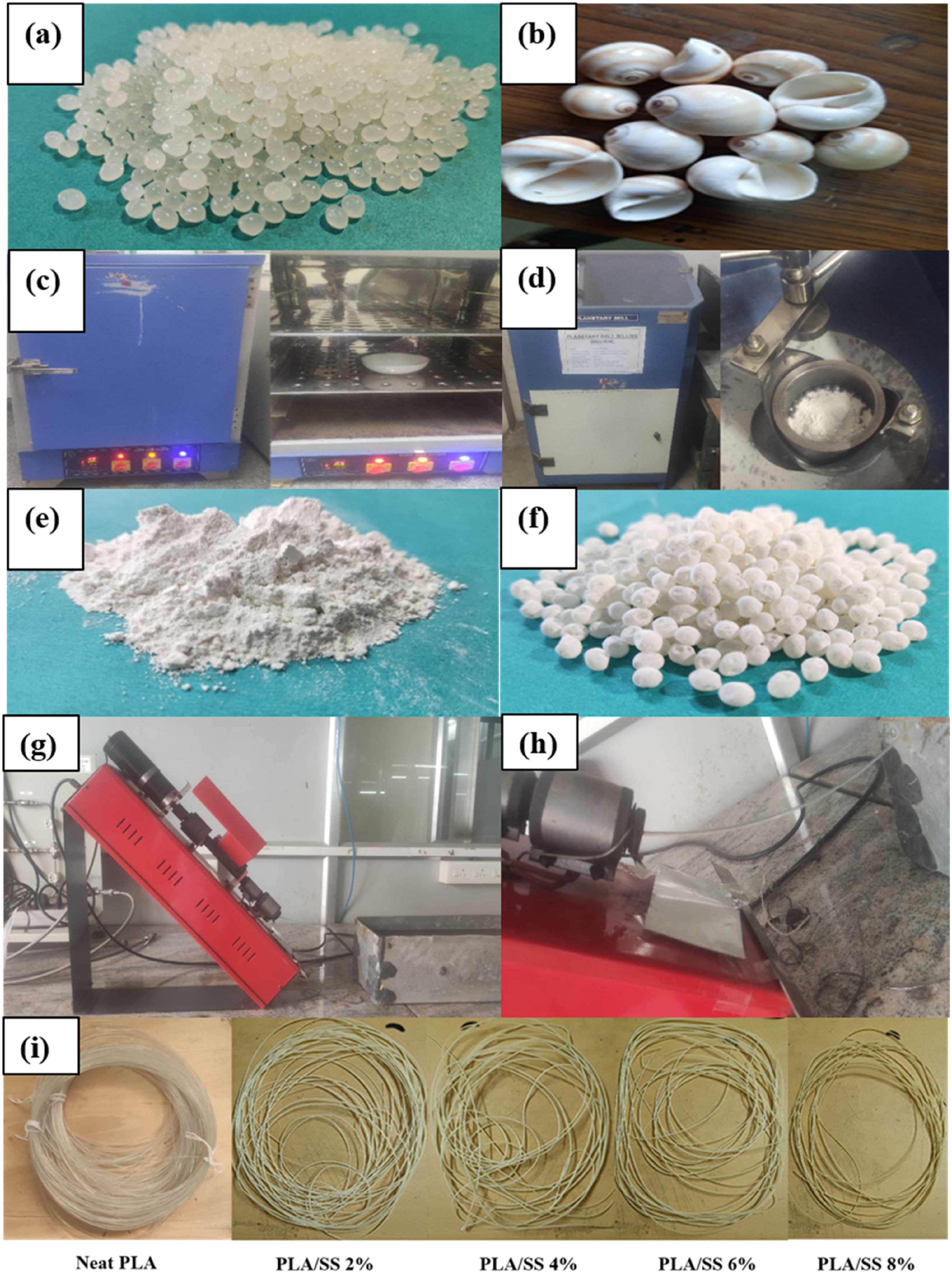
Figure 1 shows the Graphical representation of evaluation of PLA/snail shell bio-composite Filaments. PLA—2003D is a transparent extrusion-grade biopolymer procured from Nature Tech Private Limited, Chennai, in the form of granules (Figure 2(a)). This work uses a material with a specific gravity of 1.24 g/cc and a melt flow index of 6 g/10 min. Graphical representation of evaluation of PLA/snail shell bio-composite Filaments. (a) PLA granules (b) Snail shell (c) Hot air oven (d) Ball milling apparatus (e) Snail shell powder (f) Snail shell powder coated PLA granules (g) and (h) Noztec pro single screw filament extruder (i) extruded filaments.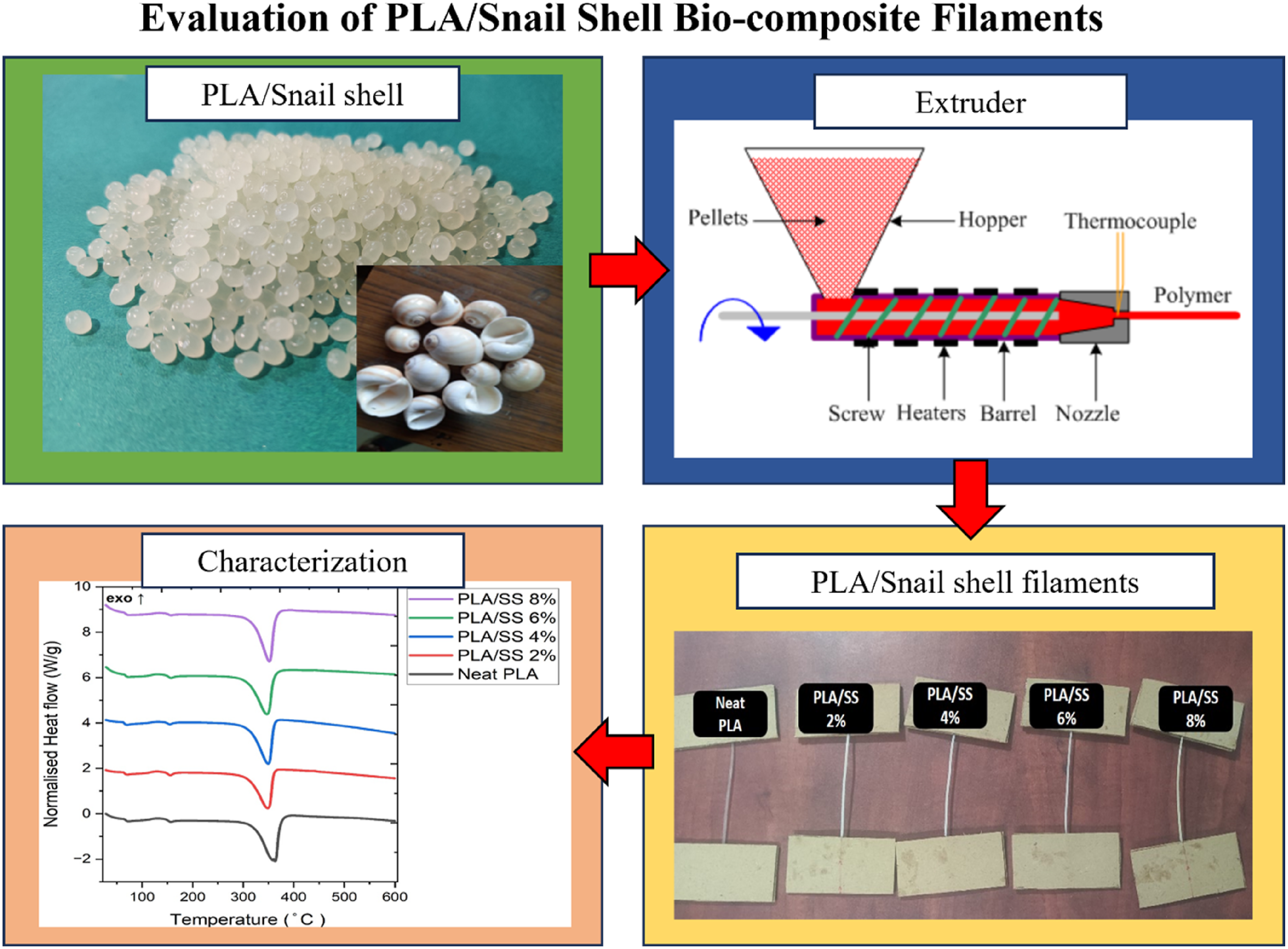
Preparation of snail shell powder
Snail shells are procured from a local supplier, as shown in Figure 2(b). They are thoroughly washed with water, cleaned with a 4M NaOH solution to remove contaminants, and rinsed with distilled water to neutralise. The washed snail shells are air dried and kept in the hot air oven shown in Figure 2(c) at 200℃ for 4 hours to remove the moisture. Then, the shells are placed in a desiccator for 1 hour to cool down without moisture absorption. The dried shells are initially crushed to coarse powder by hammering, as the material is very hard and cannot be directly used in ball milling. The coarse powder is then crushed using ball milling (Figure 2(d)) in a ratio 1:10 operated at 250 rpm for 1 hour to fine powder. Finally, the fine powder is sieved to ensure the particle size is less than 75 microns (Figure 2(e)) to avoid clogging during extrusion. The density of the prepared snail shell powder was considered as approximately 2.7 g/cm3, consistent with its primary composition of calcium carbonate (CaCO3) in calcite and aragonite forms. The higher density of snail shell particles compared to PLA (1.24 g/cm3) is expected to influence the composite packing behaviour and mechanical response.
Filament extrusion
The PLA granules and prepared snail shell powder are dried in a hot air oven to remove moisture. The snail shell powder is mixed with PLA granules in various proportions (2, 4, 6, 8 wt % SSP). Ball milling is carried out with the prepared compositions to coat the snail shell powder over the PLA granules, ensuring proper particle dispersion in the filament, as shown in Figure 2(f).
Noztec pro single screw filament extruder Figure 2(g) and (h), which is available in PSG Institute of advanced studies, is used for filament extrusion. The Noztec Pro single-screw filament extruder is equipped with a screw diameter of 16 mm and an L/D ratio of 20:1, with three independently controlled heating zones. The extruder is driven by a variable-speed motor with a maximum power rating of 0.75 kW. Temperature control accuracy is ± 1°C. A 1.61 mm diameter die nozzle was used to produce 1.75 mm filament, and dimensional stability was maintained using a controlled water bath cooling system. The extruded filament was immediately passed through a room-temperature water bath to ensure rapid and uniform cooling. The snail shell powder-coated PLA granules of various proportions are extruded to composite filaments of diameter 1.75 mm. The parameters for the extrusion are followed as per Gnanamani Sankaravel et al. to achieve the required filament diameter. 30 The filament was extruded at a temperature of 170℃ with a screw speed of 15 rpm through the nozzle diameter of 1.61 mm. Sabarinathan et al. researched on the different environmental conditions of filament extrusion and suggested that water baths gave uniform filament diameters and better mechanical properties. 31 The feed rate of extrusion required minor adjustments for various compositions (2, 4, 6, 8 wt% SSP), which are done during extrusion. The filaments of neat PLA and various compositions are extruded with a water bath and are shown in Figure 2(i). The diameter of the extruded filaments was monitored at multiple locations using a digital Vernier caliper to ensure dimensional consistency. The average filament diameter was maintained at 1.75 ± 0.05 mm for all compositions. Minor variations were observed during initial extrusion stabilization; however, steady-state extrusion and controlled water bath cooling ensured uniform solidification without significant deviation.
X-Ray diffraction
XRD analysis is performed to analyse the phase structure of the materials in snail shell powder and its composites. The PLA snail shell composites’ XRD analysis is performed with a BRUKER D8 Advanced powder X-ray diffractometer (Figure 3(a)). The test was performed using Cu-K alpha (λ = 1.54 Å) radiation, and measurements were taken for 2θ from 5° to 80°. The test was done for Snail shell powder, Neat PLA, and PLA/snail shell composite. (a) X-Ray diffractometer (b) JASCO FT/IR 6600 (c) NETZSCH STA 449 F3 Jupiter (d) Melt flow indexer (e) Instron 3365 universal testing machine (f) TESCAN VEGA3 XMU.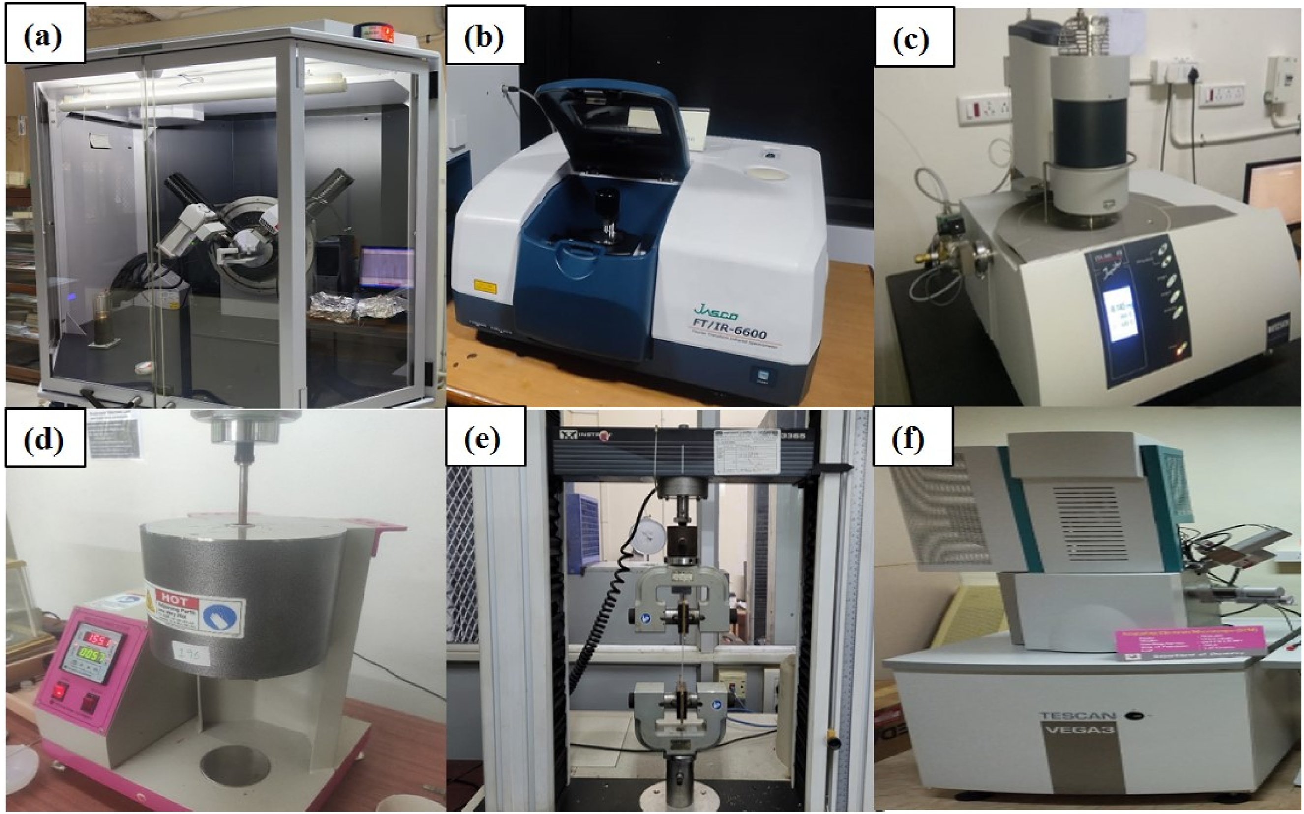
Fourier transform infrared spectroscopy
Fourier Transform infrared spectroscopy is used to identify the functional groups present in snail shell powder, neat PLA, and PLA/snail shell composite. FTIR analysis is carried out with JASCO FT/IR 6600 (Figure 3(b). The test is conducted for wavenumbers between 4000 cm−1 and 400 cm−1.
TGA/DSC analysis
Thermogravimetric analysis (TGA) is a material characterisation technique used to determine the material’s thermal stability and composites and understand the impact of filler on it. Digital Scanning Calorimetry (DSC) analysis characterises material thermally to find various thermal transition temperatures by controlled heating and cooling cycles. TGA/DSC analysis is performed with NETZSCH STA 449 F3 Jupiter Figure 3(c). PLA and various percentages of composites (2, 4, 6, 8 wt% PLA/SS) around 30 mg are tested in the form of pellets. They are heated at 10°C/min from room temperature to 600°C, and their mass percentages and normalised heat flow are recorded. The same heating cycle is used for both TGA analysis and DSC analysis.
Melt flow index
The melt flow index is used to understand the rheological properties of PLA and its composites. The test is conducted with the Melt flow indexer (Figure 3(d)) according to ASTM D1238 standards. The temperature is set to 155°C, and a load of 2.16 kg is added during the measurement.
Filament tensile test
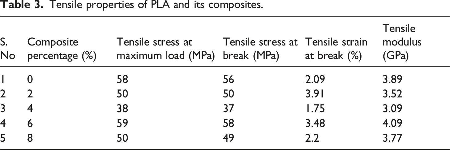
Filament tensile test is conducted to understand the effect of snail shell filler on the mechanical properties of the PLA and its composites. The test is performed according to the standards of ASTM D 3379 with Instron 3365 universal testing machine Figure 3(e) having a force capacity of 5 kN. The test is conducted for PLA and its composite filaments of diameter 1.75 mm with a strain rate of 5 mm/min. Figure 4(a) and (b) show the samples before and after the testing. All tensile tests were performed in triplicate, and the average values are reported in Table 3. (a) Tensile samples before testing (b) Tensile samples after testing.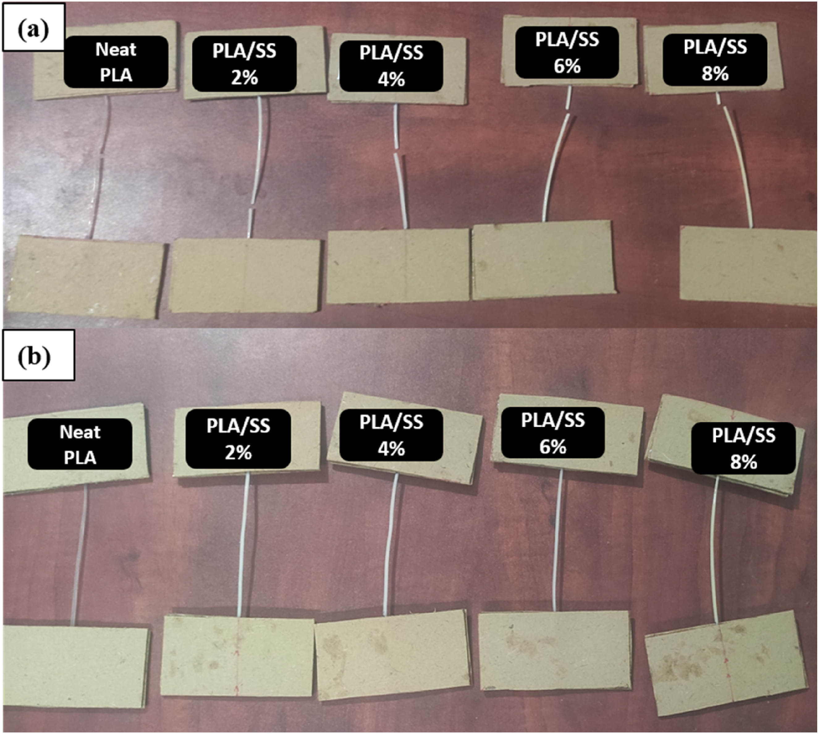
SEM analysis
Scanning electron microscope (SEM) analysis was done to study the filler dispersion over the surface and the fractured cross-section. Images of PLA/Snail shell composite filament (Figure 3(f)) are analysed using TESCAN VEGA3 XMU with magnification from 85X to 3500 X.
Results and discussion
X-Ray diffraction
The XRD of snail shell powder contains many sharp peaks, indicating its crystalline nature. Most peaks are identified as CaCO3 existing in both Calcite and Aragonite form. Figure 5(a) shows the XRD pattern of snail shell powder. The peaks corresponding to 2θ = 23.1509, 29.4806, 33.2379, 36.186, 39.5098, 43.2383, 47.5737, and 48.5564 are identified as CaCO3 in calcite form. Sattar A et al. observed similar peaks in their work and confirmed the peaks along with their phase structure as CaCO3 in calcite form with the International Centre for Diffraction Data ICDD, compared with Card No. 13397-26-7 for CaCO3.
32
The other peaks corresponding to 2θ = 26.3013, 26.7348, 27.3129, 31.5327, 37.978, 45.9262 identified as CaCO3 in aragonite form. XRD pattern of PLA and its composites (a) Snail Shell powder (b) Neat PLA (c) PLA/snail shell composite.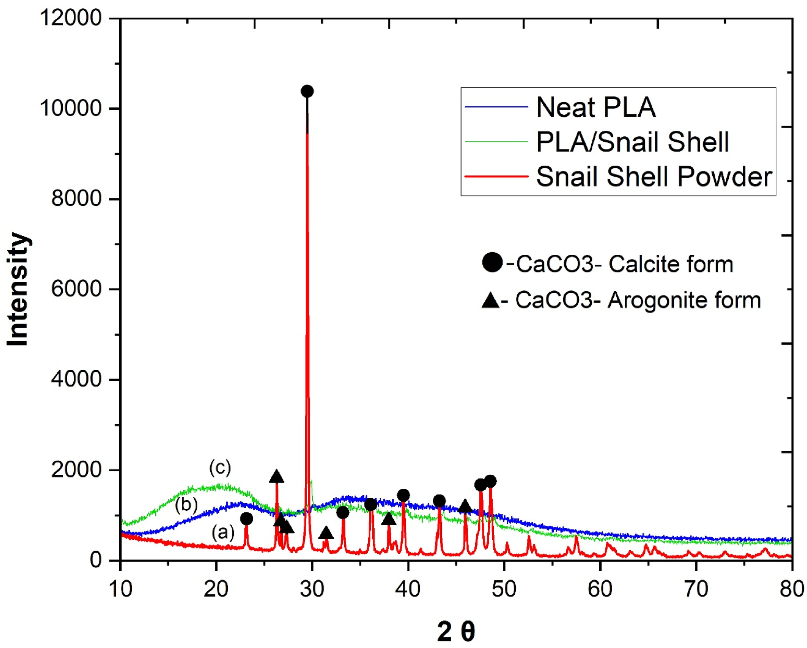
Ikbal Bahar Laskar et al. (2018) observed very similar results and confirmed from the reported data of CaCO3 (JCPDS file no. 41-1475 and 29-0306) as CaCO3 in aragonite form. 33 The above result confirms that snail shell powder predominantly consists of CaCO3, which is responsible for the hardness of snail shells. Two broad peaks were observed at 2θ = 21.12, 33.75 in the neat PLA XRD pattern (Figure 5(b)). No sharp peaks are observed, which indicates the amorphous nature of PLA material. A sharp peak was observed in the XRD pattern of PLA/snail shell composite Figure 5(c) at 2θ = 29.94, which is closer to the sharp peak of the snail shell particle observed at 2θ = 29.48. This indicates that snail shell particles interact well with PLA. No other sharp peaks are observed, indicating that the material retains its amorphous behaviour. The broad peaks observed in PLA are retained at 2θ = 21.4745, 34.3651 but with reduced intensity.
FTIR analysis
FTIR analysis is done for snail shell powder, neat PLA and PLA/snail shell composite, and a comparison of FTIR spectra is shown in Figure 6. FTIR spectrum of snail shell powder in Figure 6(a) shows a significant peak at 1395 cm−1 indicating C-H Rock alkanes, peaks at wave number 866.85, 754.995 cm−1 corresponds to = C-H bend alkenes. Peaks observed at 1452, 1639.2 cm−1 represent the C-C carbon single bonds. Peaks at 2885 and 2980 cm−1 represent the C-H stretch. These identified functional groups indicate that the powder is rich in carbon. The peaks corresponding to wave numbers 1081.87, 1128.15, 1181.19, and 1265.07 cm−1 indicate C-O stretch and peaks observed at 1747.19 cm−1 correspond to C = O group carbonyl stretching.
34
Alaa K. Mohammed et al. (2023) obtained a similar spectrum in their work.
35
These functional groups confirm the presence of CaCO3. FTIR spectra of neat PLA shown in Figure 6(b) observed with peaks at 2980 cm−1 indicate the C-H stretch and 1452 cm−1 indicate C-H bend alkanes, confirming the presence of the CH3 group in the PLA. The prominent peak at 1746.23 cm−1 indicates the C = O stretch carboxylic group. Triple peaks corresponding to 1043, 1082, and 1128 cm−1 indicate the C-O single bond.
36
A small peak observed at the far end of the spectrum in 3649 cm−1 confirms the presence of the O-H group. These groups confirm the material Polylactic acid. The FTIR spectra of PLA/snail shell composite shown in Figure 6(c) were obtained similarly to PLA with reduced peak intensities. This result confirms that no new functional group is formed during the interaction of PLA and Snail shell powder. Comparison of FTIR spectra of PLA and its composite (a) Snail shell powder (b) Neat PLA (c) PLA/Snail shell composite.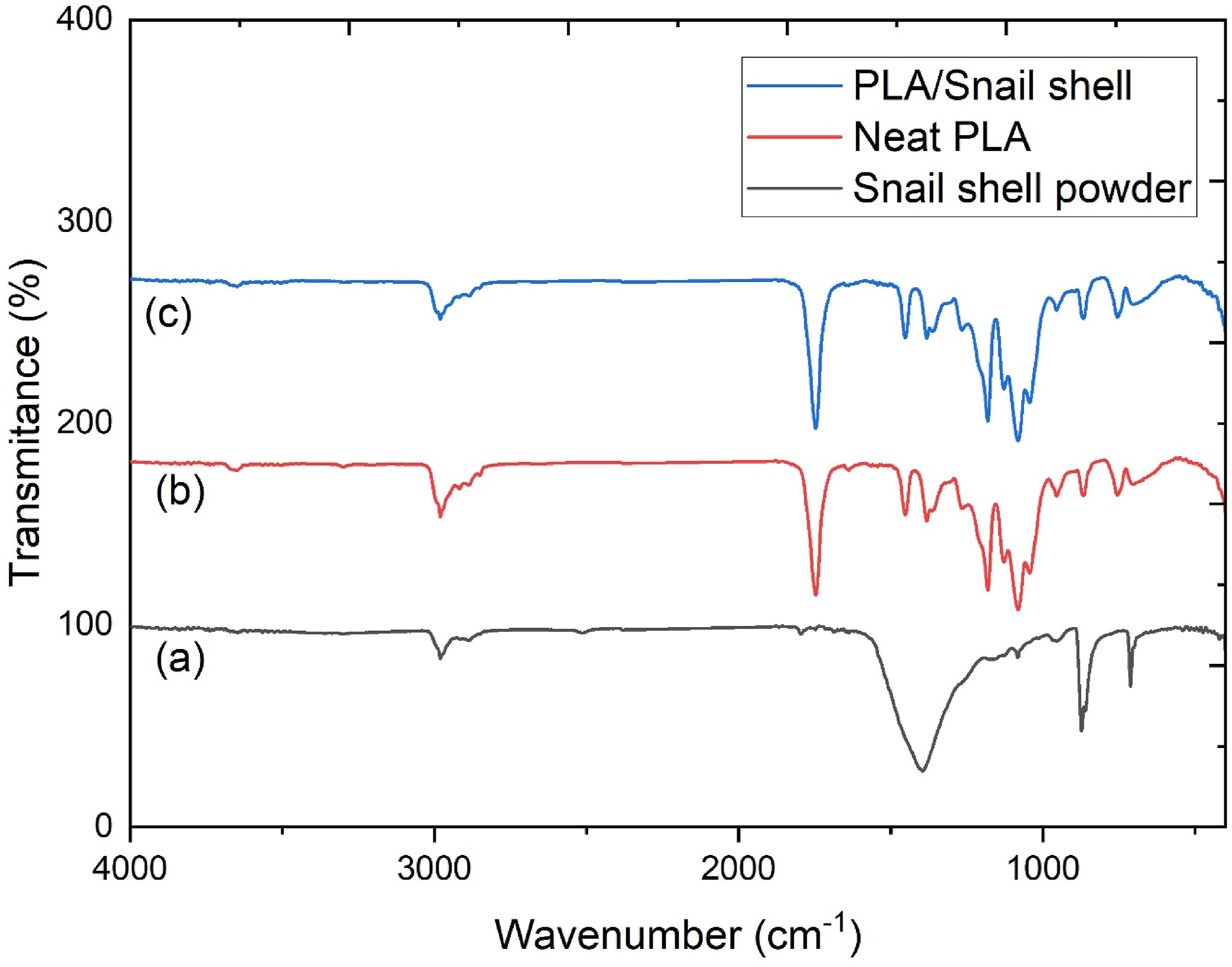
TGA analysis
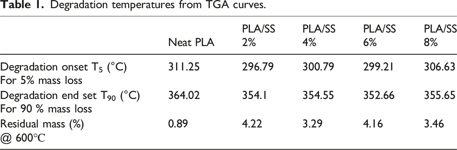
All the TGA curves show a similar pattern of single-stage degradation. The TGA curves for Neat PLA and 2%, 4%, 6%, and 8% composites are compared in Figure 7. The onset degradation temperature for 5% degradation recorded at 311.26, 296.79, 300.79, 299.21, 306.63°C for Neat PLA, 2, 4, 6, 8 wt% PLA/SS composites respectively. Adding Snail shell filler initially decreased the degradation onset temperature but saw a slight increase at 8 %.
37
This is due to better adhesion between snail shell powder and PLA. Later, it decreases again due to the agglomeration of particles. The maximum decrease in degradation temperature was observed for 2 % PLA/SS composite with a difference of 14.5°C from Neat PLA. This observation shows that the snail shell filler did not have much influence on the degradation temperature. The 90 % degradation of material attains at temperatures 364.02, 354.1, 354.55, 352.66, and 355.66°C for Neat PLA, 2, 4, 6, 8 wt% PLA/SS composites, respectively. The degradation end temperature also experiences a similar fashion as degradation onset temperatures. Noor Zuhaira et al. (2013) observed similar temperature variations in their work.
38
The residual mass at 600°C is observed with maximum weight loss obtained at 99.11% for neat PLA and minimum weight loss observed at 95.8% for 2% PLA/snail shell composites. The decrease in weight loss will be contributed by snail shell particles not decomposed in this temperature range. It is important to note that the extrusion temperature used for filament fabrication (170°C) is significantly lower than the thermal decomposition temperature of calcium carbonate, which typically occurs above 700°C. Therefore, no thermal degradation of snail shell particles is expected during the extrusion process. The residual mass observed in TGA further confirms the thermal stability of the inorganic snail shell filler within the processing temperature range. The degradation onset, end set temperatures and values of residual mass at 600°C values are shown in Table 1. Comparison of TGA curves of PLA and its composites. Degradation temperatures from TGA curves.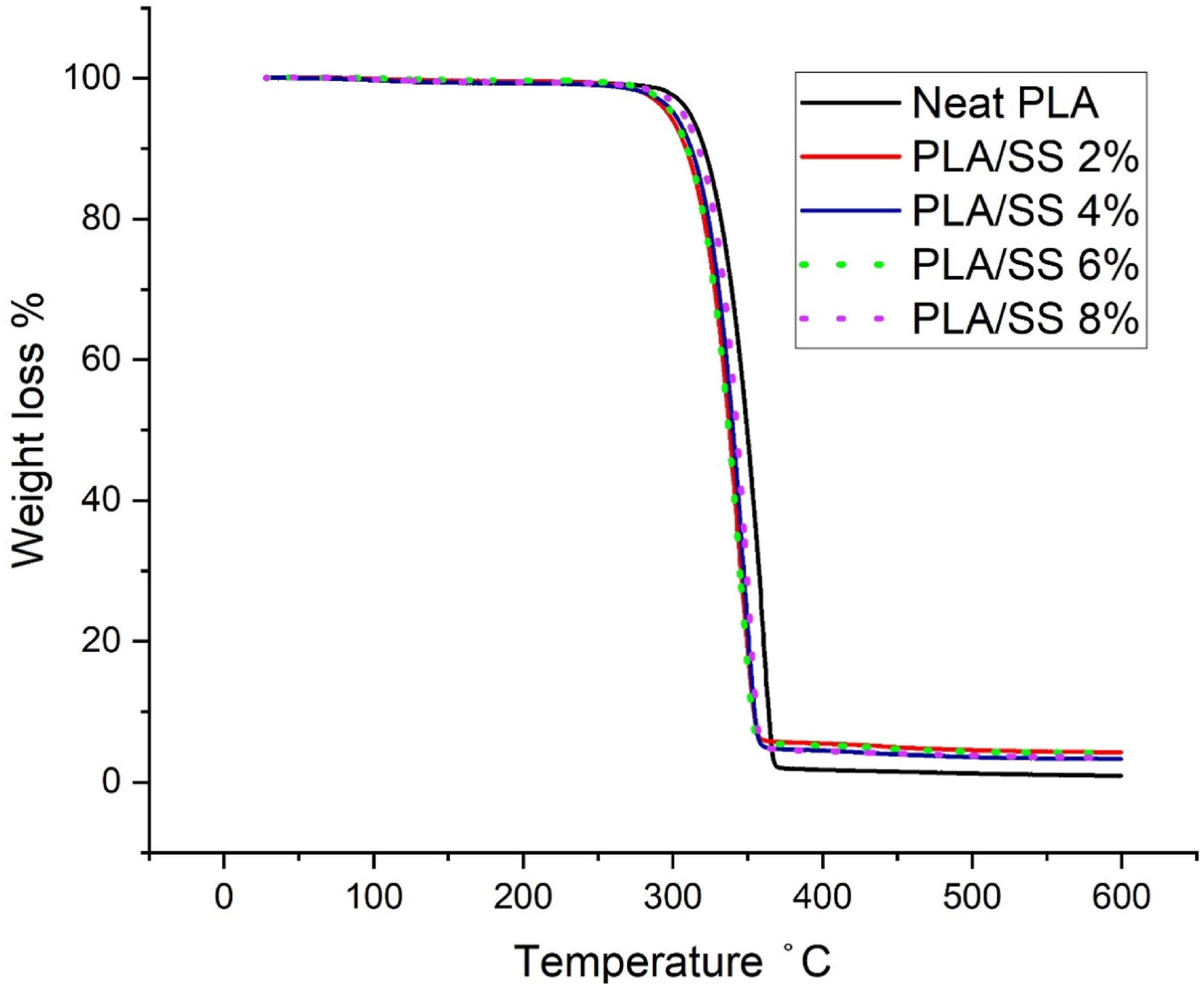
DSC analysis
The thermal transition temperatures of the material during heating cycles can be identified from the DSC curve. Similar DSC curves are obtained for PLA and its composites. The comparison of DSC curves for PLA and its composites is shown in Figure 8. Glass transition temperature defines the workable temperature of the material beyond which material softens and loses its mechanical property. Glass transition temperature of neat PLA is 68.48°C, and there are no much changes observed in their composites. The minimum glass transition temperature of 65.95°C is obtained for 2% PLA/SS composite. Thus, the working temperature of the material remains unaffected by snail shell filler content. The cold crystalline temperature represented by an exothermic peak in the graph increases from 130.871°C for neat PLA and reaches a maximum of 135.13°C for 8% PLA/SS composite. After that, it decreases upon an increase in filler content.
39
Elvira Vidovic’ et al. (2017) observed similar variations in their work of PLA/calcium carbonate composite.
40
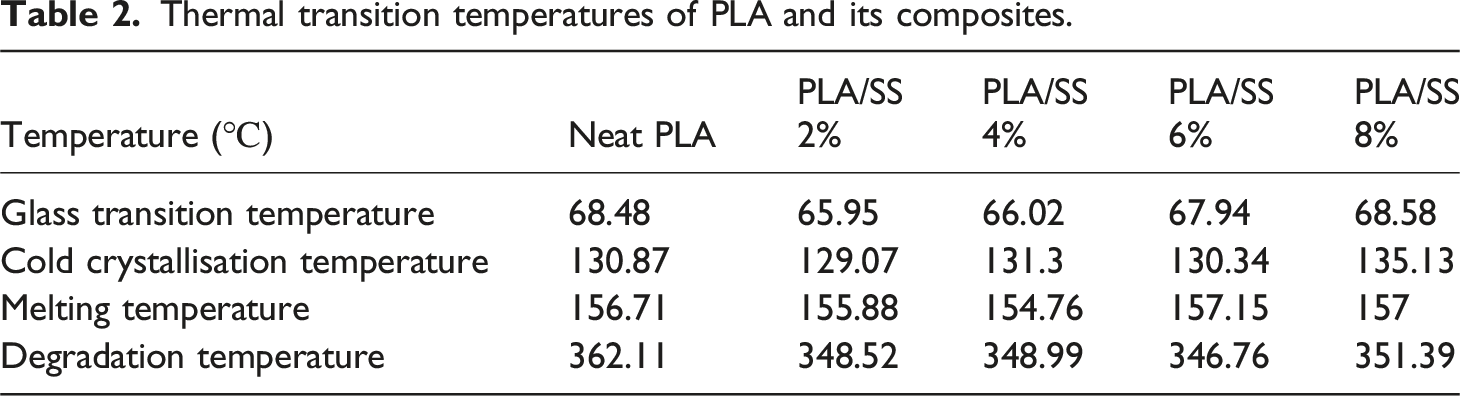
The melting point of Neat PLA and composites was observed within 2°C around 156°C. Hence, the temperature of 156°C can be considered for processing the material. The addition of filler content has a significant influence on the degradation temperature. The degradation temperature of neat PLA marks the highest value of 362.1°C, and degradation starts earlier upon the addition of filler content and observes a minimum value of 346.76°C for 6 % PLA/SS composite. Table 2 shows the transition temperatures of PLA and its composites obtained from DSC curves. Comparison of DSC curves of PLA and its composites. Thermal transition temperatures of PLA and its composites.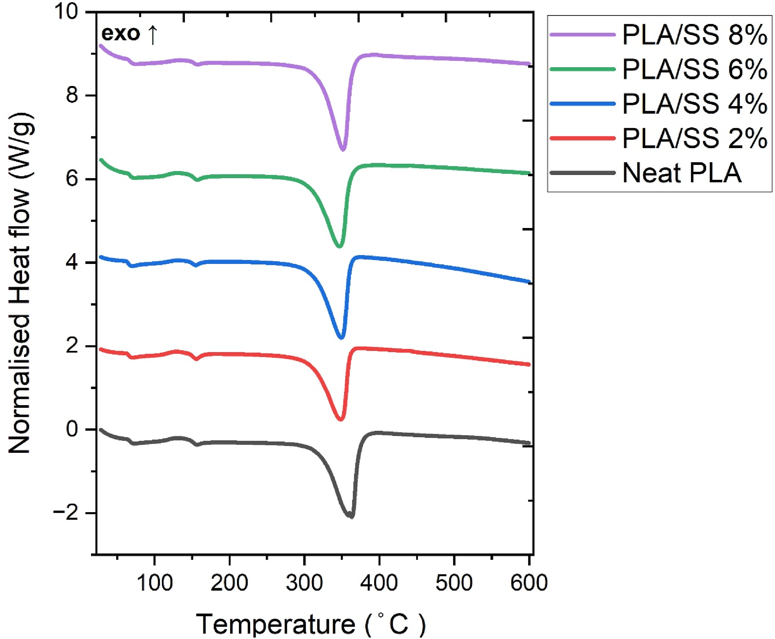
Melt flow index
The Melt flow index for PLA is observed at 6.3 g/10 min. The MFI values increase as the percentage of filler content increases. Maximum MFI was obtained for 8 % of the PLA/SS composite. This observation indicates that adding filler particles reduced the viscosity and helped with printing characteristics. A higher value of MFI is also not desirable as the material may flow in excess, which affects the printing quality. MFI less than 10 g/10 min will be suitable for 3D printing applications, as suggested by Sisi Wang et al. in their work.
41
With the obtained MFI values, all the filaments are suitable for fused deposition modelling. Figure 9 shows the comparison of MFI values of PLA and the composites. The increase in MFI at higher applied loads can be attributed to the shear-thinning behaviour of PLA-based composites. Under increased load, the shear stress and corresponding shear rate within the melt rise, leading to a reduction in apparent viscosity due to polymer chain alignment and reduced intermolecular resistance. As PLA exhibits non-Newtonian pseudoplastic behaviour, higher applied loads facilitate easier flow of the melt through the die, resulting in increased flowability. This behaviour is commonly observed in thermoplastic polymer systems. Melt flow index of PLA and its composites.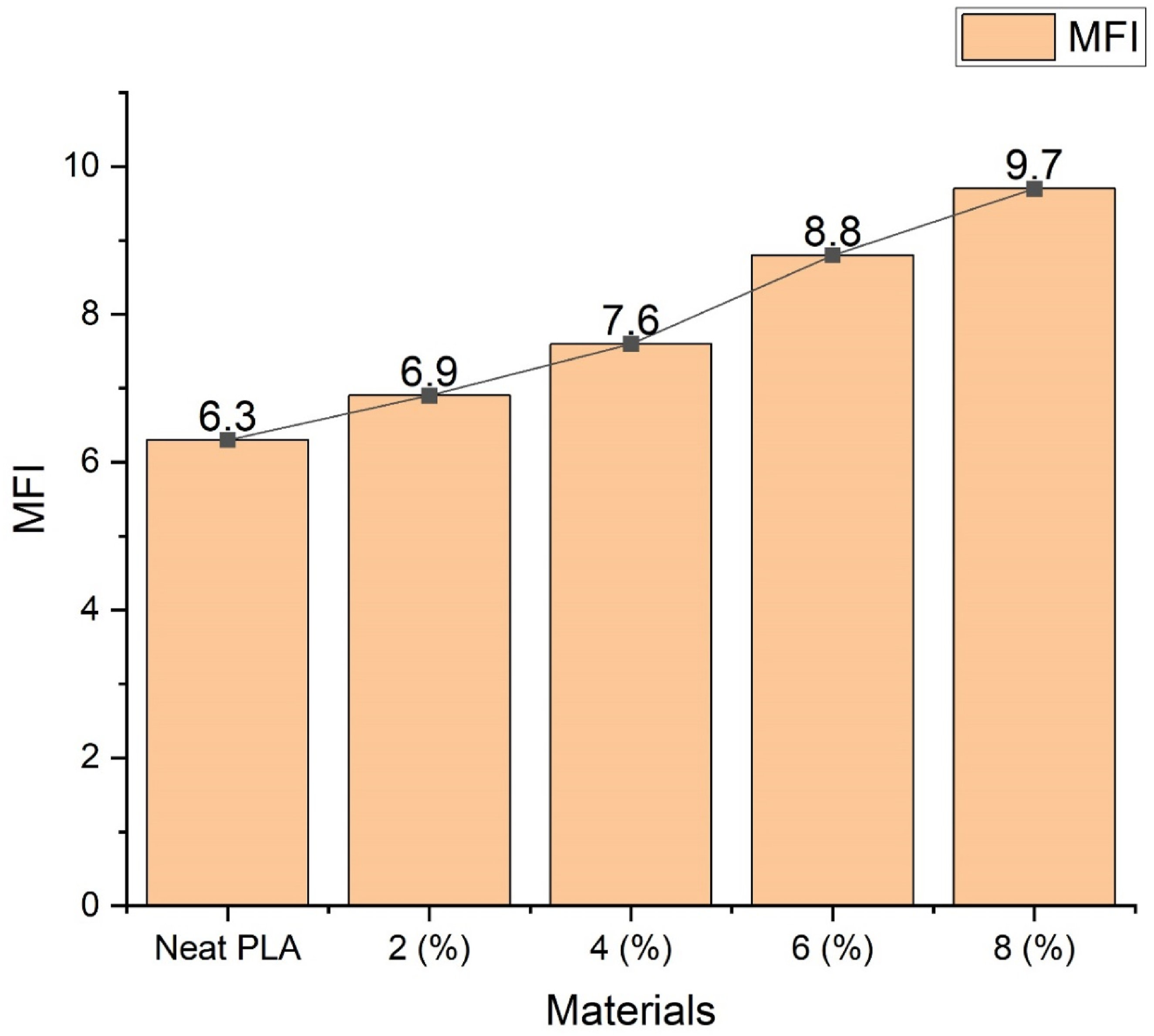
Filament tensile test
The influence of snail shell filler on mechanical properties is studied using a filament tensile test. Figure 10 (a)–(e) shows the stress-strain curves obtained for PLA and its composites. The tensile strength of PLA/Snail shell 6% composite marks the highest tensile value of 59 MPa compared to Neat PLA, which has a value of 58 MPa. However, a further increase in filler content reduced the tensile strength due to the agglomeration of particles. The non-linear variation in tensile strength with filler loading can be attributed to competing mechanisms of reinforcement and stress concentration. The effectiveness of reinforcement depends on homogeneous load distribution within the polymer matrix. At optimal filler loading (6 wt%), the snail shell particles appear to be sufficiently dispersed, enabling efficient stress transfer from the ductile PLA matrix to the rigid CaCO3 particles. This improved interfacial interaction enhances tensile strength and modulus. However, when dispersion is not fully uniform, localized stress concentration regions may develop, resulting in premature failure and fluctuations in tensile values. At lower filler contents (2–4 wt.%), inadequate interfacial bonding and localized particle agglomeration may create stress concentration sites, resulting in premature failure and reduced tensile strength. At 6 wt% filler loading, improved dispersion and effective stress transfer between the PLA matrix and rigid CaCO3-based snail shell particles likely contributed to enhanced load-bearing capacity, yielding the highest tensile strength. Beyond this optimal content (8 wt%), increased particle–particle interaction and agglomeration reduce matrix continuity, leading to a decline in mechanical performance. Such non-linear behaviour is commonly observed in particulate-reinforced polymer composites. The tensile modulus of Neat PLA is observed at 3.89 GPa. Significant changes are observed with the tensile modulus of PLA and its composites, with the highest value of 4.09 GPa for 6 % and the lowest value of 3.09 GPa for 4% composite. This result indicates that the material gets stiffer due to the addition of snail shell filler. Elongation at break, a measure of the material’s ductility, is observed at 2.09 % for neat PLA. The elongation at break improves upon filler addition up to 6%, marking its highest value of 3.48 %, indicating an improvement in ductility. The value gets reduced on further increase in filler content as they may interrupt the molecular movement of PLA. The lowest value was observed with a 4% composite with a value of 1.75 %. Higher filler loading beyond 6 wt% reduced ductility due to particle clustering and reduced matrix continuity. The obtained results agree with the work of Sivagnanamani et al. in their PLA/Eggshell composite.
30
The tensile properties of materials are shown in Table 3. These variables can cause oscillations in mechanical performance and lower ductility. Furthermore, high filler loading might affect melt flow behavior and dimensional stability during extrusion. Therefore, careful adjustment of filler content is required to balance reinforcement and processability in PLA-based composites. As a result, the observed differences in tensile characteristics are linked to changes in particle dispersion and load transmission efficiency within the matrix. Interfacial bonding and uniform filler dispersion have a significant impact on the homogenous load distribution of particulate-reinforced composites. Any grouping of stiff particles disrupts matrix continuity and causes unequal stress distribution during tensile loading. Stress-Strain curves of PLA and its composites (a) Neat PLA (b) PLA/SS 2% (c) PLA/SS 4% (d) PLA/SS 6% (e) PLA/SS 8%. Tensile properties of PLA and its composites.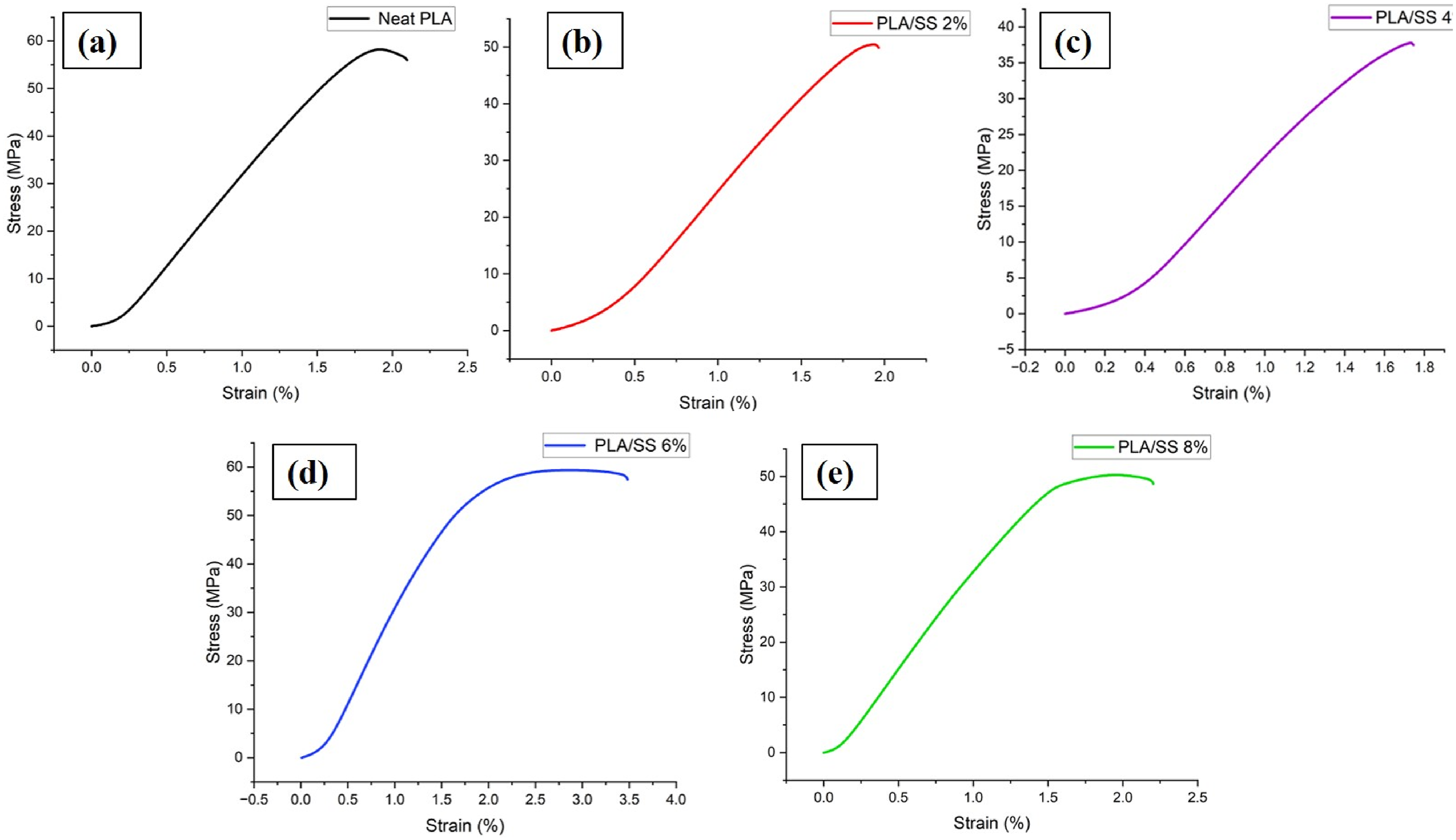
SEM analysis
The filler distribution over the PLA matrix is studied using SEM analysis. The image of a fractured cross-section of the filament failed the tensile test, and the surface of the filament was taken with a Scanning Electron Microscope (SEM). From Figure 11(a), the smooth surface of the filament is observed, which shows the good quality of the filament manufactured. Minor scratches on the surfaces are observed, which can be seen in the magnified image in Figure 11(b). Snail shell particles on the surface of the filament are seen on the magnified image, confirming good filler dispersion.
42
Figure 11(c) shows the SEM image of the fractured cross-section of the filament. The plastically deformed region at the cross-section confirms the material’s ductility. This image also confirms the uniform dispersion of Snail shell particles. The agglomerations are seen very few in the image. Although overall dispersion appears satisfactory, minor localized agglomerations were observed. These regions can act as stress concentration sites under tensile loading and may influence the homogeneity of load distribution within the PLA matrix, which correlates with the variations observed in tensile properties. The fractured surface also showed evident surface pull-out during fracture, confirming better adhesion of snail shell filler with PLA matrix.
43
SEM image of the PLA/SS filament (a) Surface of the filament (b) Magnified image of surface (c) Fractured cross section.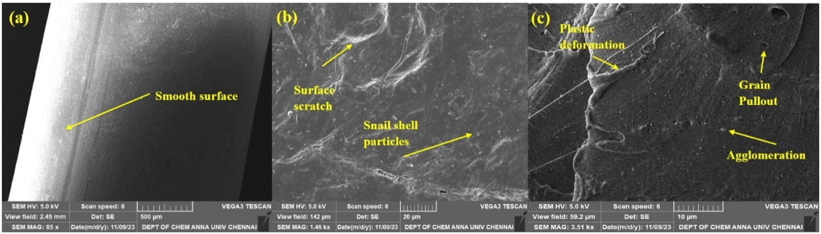
Conclusions
The present study successfully extruded PLA/snail shell composite filaments with filler loadings of 2, 4, 6, and 8 wt% and evaluated their chemical, thermal, and mechanical characteristics to understand the influence of snail shell addition on material performance. XRD analysis confirmed that the snail shell powder primarily consists of crystalline CaCO3, while FTIR results indicated that no new functional groups were formed within the composites. Thermal analyses showed only minor variations in thermal behaviour: TGA revealed degradation temperatures ranging from 311.25°C for neat PLA to 296.79°C for the 2 wt% composite, and DSC indicated slight shifts in transition temperatures, with melting points remaining close to ∼156°C across all compositions values suitable for FDM processing. Rheological assessment showed increased MFI with higher filler content, rising from 6.3 g/10 min for neat PLA to 9.7 g/10 min for the 8 wt% composite, confirming good printability. Mechanical testing revealed enhanced performance at specific filler ratios, with the 6 wt% PLA/snail shell composite achieving the highest tensile strength of 59.41 MPa and improved ductility, as reflected by increased tensile strain at break for the 6 wt% (3.48%) and 8 wt% (2.2%) composites compared with neat PLA (2.08%). SEM observations of fractured surfaces further supported these trends by showing plastically deformed regions and a uniform dispersion of snail shell particles across the PLA matrix. Overall, the findings indicate that PLA/snail shell composites up to 8 wt% exhibit favourable mechanical, thermal, and rheological properties, making them suitable candidates for 3D printing applications. Based on the obtained mechanical, thermal, and rheological properties, the developed PLA/snail shell composite filaments demonstrate strong potential for FDM applications, including lightweight structural components, customized biodegradable products, and prototype fabrication. Due to the calcium-rich bioceramic nature of snail shell, the material may also be considered for potential scaffold fabrication in tissue engineering applications. However, although the present study confirms favourable processing and mechanical performance, comprehensive biological evaluations such as in vitro cytotoxicity and cell compatibility studies are required prior to clinical or biomedical implementation and will be addressed in future work.
Footnotes
Declaration of conflicting interests
The authors declared no potential conflicts of interest with respect to the research, authorship, and/or publication of this article.
Funding
The authors received no financial support for the research, authorship, and/or publication of this article.