
Abstract
Carbon fibre steering offers a pathway to designing composite susceptors that could replace metallic inserts in the induction welding of carbon fibre–reinforced polymer laminates. By tailoring the fibre architecture, the composite itself can act as an integrated susceptor capable of controlled electromagnetic heating. A finite element model is developed in COMSOL Multiphysics to predict temperature evolution and current concentration within such tailored laminates. The model is first validated using unidirectional samples with fibre orientations of 0°, 90°, +45°, and −45°, and subsequently extended to complex susceptor configurations, including circular, concentric, and quasi-isotropic designs. The simulation explicitly accounts for local mesostructural effects to capture anisotropic conduction and edge effects governing heat distribution. Results indicate that the concentric configuration achieves the highest peak temperatures with strongly localised heating; the circular pattern yields radially symmetric temperature fields, and the quasi-isotropic layup provides uniform but less intense heating. Experimental infrared thermography confirms these trends, showing good agreement with model predictions. The work demonstrates that susceptor geometry can be engineered through fibre steering to control induction heating behavior, providing a lightweight, corrosion-free, and sustainable alternative to metallic inserts for joining and repair of thermoplastic composites in aerospace and automotive applications.
Introduction
Induction welding has emerged as a promising method for joining Carbon Fibre-Reinforced Polymer (CFRP) composites, offering a cleaner and faster alternative to mechanical fastening and adhesive bonding.1–3 The process generates heat through electromagnetic induction, while pressure consolidates the bond line. Its adoption in aerospace structures has demonstrated clear benefits; for example, implementation in the Gulfstream G650 rudder reportedly reduced manufacturing costs by 20% and weight by 10%.2,4 Such improvements highlight the potential of induction welding to contribute to more fuel-efficient aircraft and reduced emissions.
Most research on induction welding has focused on woven and Unidirectional (UD) composite laminates, both of which have demonstrated reliable joint quality when process parameters and susceptor designs are optimised.3,5–7 Although woven laminates naturally provide multiple conductive pathways that facilitate uniform heating, significant advances have also been achieved for UD laminates through improved susceptor placement, coil design, and process control.3,5–7
Metallic foils and meshes remain commonly employed as susceptors to enhance local heating, though they can introduce drawbacks such as corrosion susceptibility, mechanical discontinuities, recyclability challenges, and increased process complexity. 5 Recent studies have also shown that susceptor geometry strongly influences heating distribution and joint integrity.3,8 Furthermore, the emergence of additive manufacturing and fibre-steering technologies enables tailored fibre orientations that can modulate current flow and heat generation within UD laminates. However, while promising, the combined effects of fibre architecture and susceptor geometry on heating behavior and weld quality remain incompletely characterised.9,10
Heating mechanisms in CFRP laminates arise from multiple contributions, including Joule heating in the fibres, dielectric hysteresis at the fibre–matrix interface, and contact resistance at fibre junctions.5,10,11 The relative importance of these mechanisms depends on fibre orientation and fibre volume fraction. Even composites with nominally similar layups can exhibit different heating behavior due to microstructural variations.1,12–14 While woven laminates facilitate current loops that promote uniform heating, UD laminates try to drive current through transverse or through-thickness directions, which are orders of magnitude less conductive than the fibre-aligned direction.3,5,13,15 Reported conductivities range from 8000 to over 39,000 S/m along the fibre direction, compared with only 3–11 S/m transversely or through-thickness.5,16,17
To date, no comprehensive study has compared the thermal performance of different susceptor geometries, nor has it used both Multiphysics modelling and experimental validation.9,13,18–21 Moreover, while many earlier models simplified boundary conditions by neglecting mesostructural features such as sample edge effects, recent studies have demonstrated that these effects play a significant role in current concentration and local heating during thermoplastic induction welding, as shown by Barazanchy et al. and Martin et al.20–24 This work addresses that gap by developing finite element models in COMSOL Multiphysics that account for mesostructure non-uniformities to predict the thermal behavior of three susceptor layups. The model is validated against experimental heating profiles for simple CFRP laminates with 0°, 90°, +45° and −45° fibre orientations. The effect of susceptor layup on thermal uniformity and heating efficiency is then assessed to establish comparative design guidelines and performance trade-offs for composite welding applications, linking fibre architecture to heating localisation, intensity, and spatial distribution.
The remainder of this paper is structured as follows. Section II describes the method including the modelling framework, with the finite element implementation in COMSOL Multiphysics, and the experimental procedures, covering sample fabrication, printing, and thermal testing. The Results section presents a comparison between numerical predictions and experimental observations. The Conclusions section summarises the main findings of the study and outlines potential directions for future work.
Methods
A combined modelling and experimental workflow were implemented. A finite element model was first developed in COMSOL Multiphysics to simulate the temperature distribution within UD CFRP samples (0°, 90°, +45° and −45° fibre orientations) under induction heating. The CFRP laminates were produced by 3D Continuous Carbon Fibre (CCF) strands within a nylon thermoplastic matrix. This qualifies them as CFRPs as the carbon fibres act as the reinforcement phase, providing mechanical strength and electrical conductivity, while the nylon serves as the polymer matrix, binding the fibres together. The COMSOL model was initially validated using simple UD samples with uniform fibre orientations (0°, 90°, +45°, and −45°) as shown in Figure 1. These validation samples were fabricated using the Markforged Mark Two 3D printer and experimentally evaluated under induction heating. Compared with conventional UD CFRP laminates, the 3D-printed samples exhibited a distinct mesostructure resulting from the continuous fibre deposition process, as described in section “Geometry and Domain Setup”. This difference in internal architecture influenced the local heating distribution, which was accounted for during model validation. The resulting experimental temperature profiles were compared with COMSOL simulations to confirm that the model accurately captured the measured anisotropic heating behavior. Top view of the UD layup details of CCF sample showing 0°, −45°, 90°, 45°.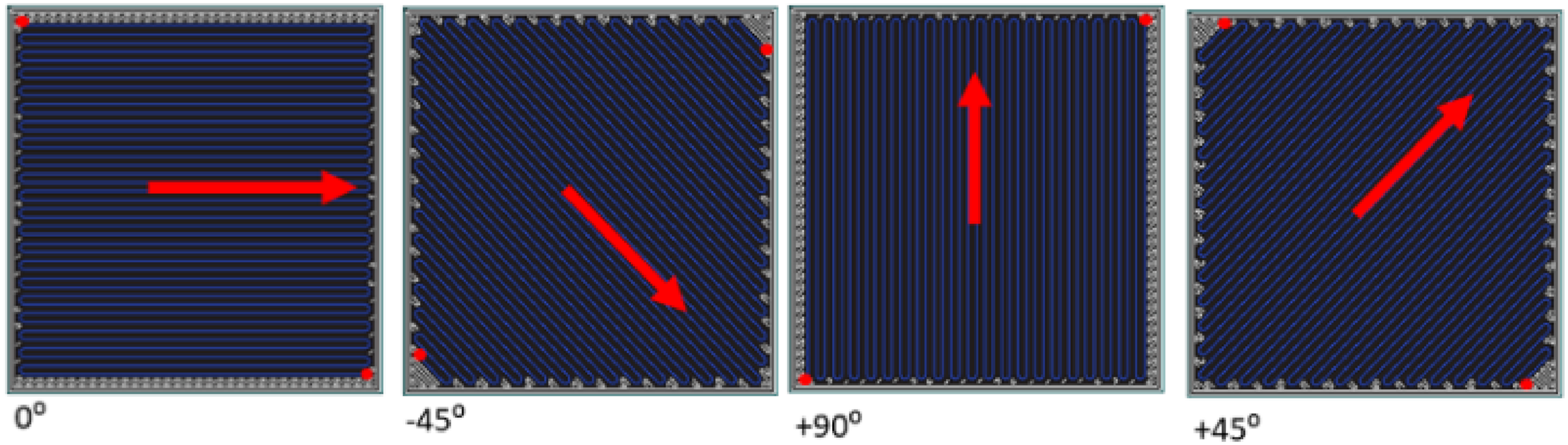
Following the validation, the finite element model was applied to investigate three complex designs of susceptors shown in Figure 2; circular, concentric, and Quasi-Isotropic (QI). These designs represent potential integrated susceptors, created through controlled fibre orientation and distribution. Each configuration was 3D printed and modelled under the same experimental induction conditions, enabling direct comparison between simulation and experiment. The goal was to determine which susceptor layup provides the most thermal uniformity and heating efficiency, then identify optimal design parameters for composite welding applications. Geometric layouts of the proposed fibre-based susceptors: (A) circular, (B) concentric, (C) top-view of the QI layout, and (D) side-view schematic of the QI stacking sequence.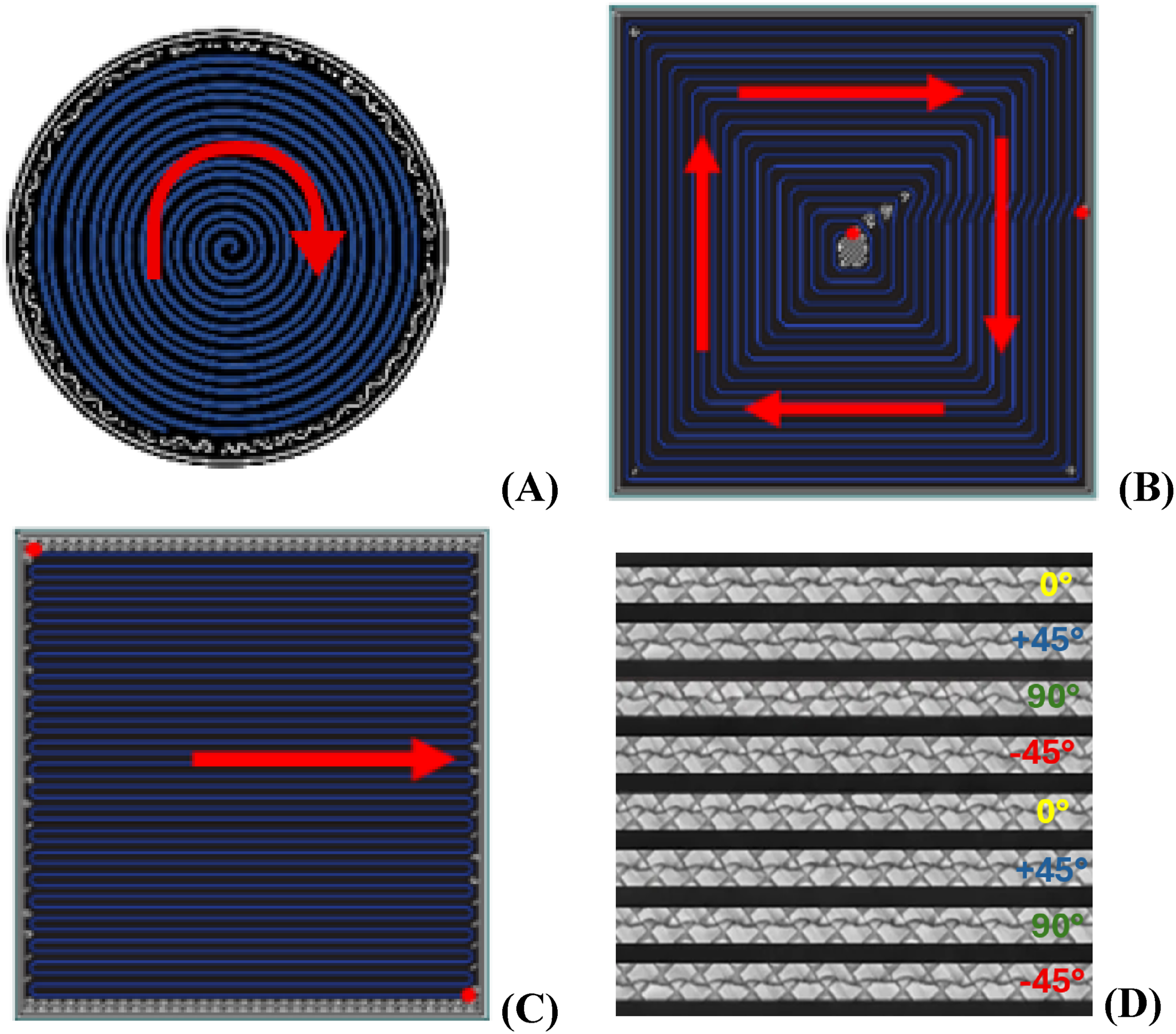
Sample manufacturing
All samples were fabricated using a Markforged Mark Two 3D printer, which employs a dual-nozzle extrusion system. The samples were printed using the default Markforged Eiger settings. For the 40 × 40 mm, 8-layer laminates investigated in this study, the total printing time was approximately 10 to 15 min per sample, corresponding to a continuous fibre deposition speed on the order of 10 mm/s. For the present study, the roof and floor layers normally deposited by the polymer nozzle were excluded. These polymer roof and floor layers were removed because prior work has shown that surface polymer skins act as thermal and electrical barriers that reduce heating intensity and modify current distribution in welded composite laminates. Studies on fusion bonding and thermoplastic welding have reported that these layers insulate the underlying susceptor and attenuate the formation of surface heat fronts during induction heating.1,10,25 In addition, research on induction welding edge behavior has demonstrated that polymer layers can shield critical edge regions and suppress edge driven current concentration effects that strongly influence temperature localisation.24,25 The CCF filament (0.4 mm diameter) consists of continuous carbon fibres pre-impregnated with nylon at a fibre volume fraction of ∼34%.26,27 Printing was controlled through the proprietary Eiger software, which enables fibre orientation control on a layer-by-layer basis.
Each laminate measured 40 mm × 40 mm, with 8 fibre layers, yielding an approximate thickness of 1 mm. Within each fibre layer, strands were deposited in a raster pattern, turning back at the edges to run parallel across the sample.
These turning regions (Figure 4) were explicitly represented in the COMSOL models, as they introduced local fibre redirection that strongly influences anisotropy and heating response. During deposition, the fibre nozzle operated at 255°C.
Sample descriptions
Validation samples
To verify the accuracy of the COMSOL thermal model, four samples were printed with UD fibre orientations and no geometrical complexity. Each consisted of 8 CCF plies aligned in a single direction: • 0° Layup: All fibres aligned with machine X-axis. • 90° Layup: All fibres aligned along the Y-direction. • +45° Layup: All fibres oriented at +45° to the X-axis. • −45° Layup: All fibres oriented at −45° to the X-axis
Fibre-based susceptor design samples
Three designs of susceptor were proposed to investigate their thermal behavior under induction heating.
The first design is the circular layup, seen in Figure 2(a). It consists of a laminate built from eight layers of continuous carbon fibre, initially oriented at 0° but routed in a continuous circular path. Circular fibre steering has been suggested to modify current loops in conductive laminates.9,28 For this paper it was evaluated for its ability to concentrate heating toward the center and generate a radial temperature profile.
The second design is the concentric layup, seen in Figure 2(b). Similar to the circular layup, it uses 0° layers but with fibres arranged as nested square rings. Inspired by earlier work showing that geometric symmetry can influence current pathways, this design aimed to enhance thermal uniformity from the edges toward the center.21,29,30 In the printed samples, the start and end points of the continuous fibre paths are defined by the printer’s default toolpath planning strategy and are located along one edge of the square, resulting in a minor local geometric asymmetry. In the numerical model, the concentric layup was represented as an idealised nested square geometry in order to focus on systematic mesostructural features governing current redirection and edge heating.
The third design is the QI layup seen in Figure 2(c). The QI layup is the most complex of the three proposed layups. It employs a balanced stacking sequence of UD layers [0/+45/90/−45/0/+45/90/−45], commonly adopted in structural applications for its in-plane isotropy.31,32 Its inclusion allowed assessment of whether multi-directional fibre orientations could distribute current more evenly and yield a more uniform heating response. 30
COMSOL modelling methodology
Geometry and domain setup
To support and interpret the experimental results, a finite element model replicating the induction heating setup was developed using COMSOL Multiphysics 6.3. All geometrical dimensions, material properties, and excitation parameters were derived directly from the experimental setup to ensure consistency between simulation and measurement.
Each model contained three principal domains: a copper coil, a CFRP sample, and a surrounding air domain. The copper coil geometry was defined as a ring with a 17 mm outer diameter and 3 mm tubing diameter and was assigned copper properties from the COMSOL materials library. In the numerical model, the coil was represented using a rectangular cross section conductor with an equivalent area rather than a circular 3 mm tube. This geometric simplification was chosen to improve mesh stability and reduce computation time while preserving the magnetic field distribution in the region of interest. This approach is consistent with standard electromagnetic modelling practice, as the induced magnetic field and resulting eddy-current distribution in the laminate are primarily governed by the overall coil geometry and excitation current, and are not strongly sensitive to the precise conductor cross-sectional shape when the equivalent area is preserved. Under these conditions, the precise rounding of the conductor has negligible influence on the predicted fields and heating behavior, as supported by electromagnetic theory and numerical studies.33–35 To replicate the experimental setup, electrical excitation of the coil was implemented through perpendicular current terminals defined at the coil boundaries in the Magnetic Fields (mf) interface. These terminals represent the current input and output points (as shown in Figure 3, red and black markers), corresponding to the generator connections in the physical system. The applied current was implemented to match the 40% power setting of the Ceia Powercube 45/900 generator used experimentally. At this setting, the generator displayed an output voltage of 109.4 Vrms (40% power). The coil current applied in the electromagnetic model was initially estimated based on the generator voltage output settings provided by the manufacturer and the calculated impedance magnitude of the coil (based on inductance of 47.5 nH). This approach assumes that the coil itself dominates the impedance seen by the generator. Full COMSOL model with the coil, the sample and air.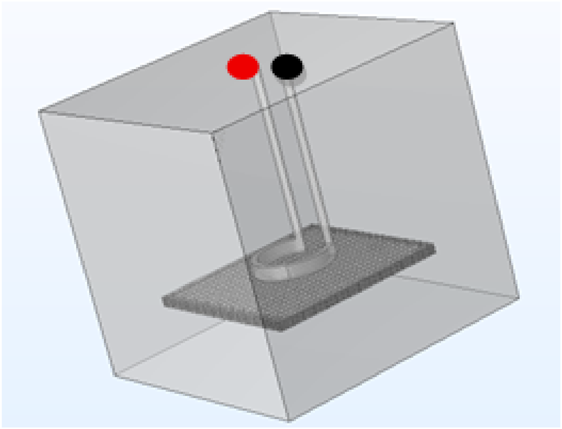
During comparison with experimental temperature measurements, a systematic overestimation of temperature was observed across all configurations. Further examination of the electrical power path indicates that this discrepancy is most plausibly attributed to additional series resistance in the current path between the generator and the coil. In practice, the supplied AC voltage is delivered through internal switching devices (e.g., MOSFETs or IGBTs), as well as interconnects and connectors. Such elements typically contribute an additional resistance on the order of 0.5–1 Ω.
Because the induction generator does not provide a direct measurement of coil current and the internal circuitry is not accessible, the effective current delivered to the coil cannot be accurately determined from first principles. The coil current used in the COMSOL simulations was therefore adjusted to 235 A, a value consistent with the expected reduction in current resulting from the additional series resistance of the switching devices and interconnections. This calibrated current yields agreement between simulated and experimental temperature magnitudes while preserving the relative heating trends across all fibre architectures. The same current value was applied consistently across all simulations presented in this study.
All samples were modelled 2 mm below the coil and surrounded in a 100 mm × 100 mm × 100 mm cube of air, initialised at 20°C to match the initial temperature recorded during the experimental work.
A free tetrahedral mesh was used, the element size ranged from 0.4 mm (minimum) to 1.95 mm (maximum), resulting in 246,000 degrees of freedom per simulation.
The simulation workflow was implemented in three stages. First, coil geometry analysis was performed to validate meshing quality and spatial configuration. Second, a frequency-domain study was solved at 1.046 MHz using the Magnetic Fields (mf) interface to compute eddy currents and volumetric power dissipation. Finally, a time-dependent heat transfer study was carried out with the Heat Transfer in Solids (ht) interface to predict the transient temperature field. The time-dependent thermal study spanned 3 s (0.1 s time steps), with 1 s heating time (current applied) and 2 s cooling time (the time when the thermal image was recorded experimentally). Both steps used a fully coupled solver configuration with default convergence criteria and a relative tolerance of 10−8. A PARDISO direct solver was employed to handle the large system of equations generated by the coupled electromagnetic–thermal model. This solver computes solutions by factorising the system matrix rather than using iterative approximations, which ensures convergence and numerical stability across all simulation cases. Electromagnetic heating was coupled to the thermal domain through the power dissipation term:

Natural convection (heat transfer coefficient: 10 W/m2·K) was applied to all outer faces of the air domain. Thermal insulation boundary conditions were applied at the outer surfaces of the surrounding air domain, representing an assumption that no heat is lost beyond the modelled volume. Internal boundaries, such as the coil–air and air–sample interfaces, were left unconstrained so that heat transfer and electromagnetic coupling could occur naturally.
During modelling of the validation geometries laminates in COMSOL Multiphysics, the mesostructure generated by the 3D-printing process was explicitly incorporated. The individual turns introduced at the sample edges during the printing path were preserved in the model to accurately capture fibre steering and its influence on local anisotropy. Specifically, the curved or angled regions formed at the laminate edges during fibre redirection were explicitly segmented into discrete mesostructural regions. Each segment represents a localised fibre orientation corresponding to the direction of the printing path within that region. Each mesostructure segment was then assigned to orientation-specific material properties (0°, 90°, +45°, and −45°), as illustrated in Figure 4. This segmentation allows the model to account for gradual changes in fibre orientation at the edges, rather than imposing abrupt orientation jumps, thereby providing a more realistic representation of current flow and local heating behaviour in fibre-steered laminates. This approach ensures that the simulated laminates reproduce not only the macroscopic stacking sequence but also the mesoscopic effects of fibre redirection at the edges of the samples, providing a more realistic representation of current flow and heat generation during induction heating. While the mesostructural segmentation captures smoother fibre steering at the edges and provides a closer approximation to the printing path than abrupt orientation changes, it remains an idealised representation of the printed samples and does not resolve all local toolpath-level variations. Geometric representation of fibre mesostructural turns from 3D printing with assigned ply orientations. (A) turns from Model 90°, (B) turns from Model 0°; (C) turns from Model +45°, (D) turns from Model −45°.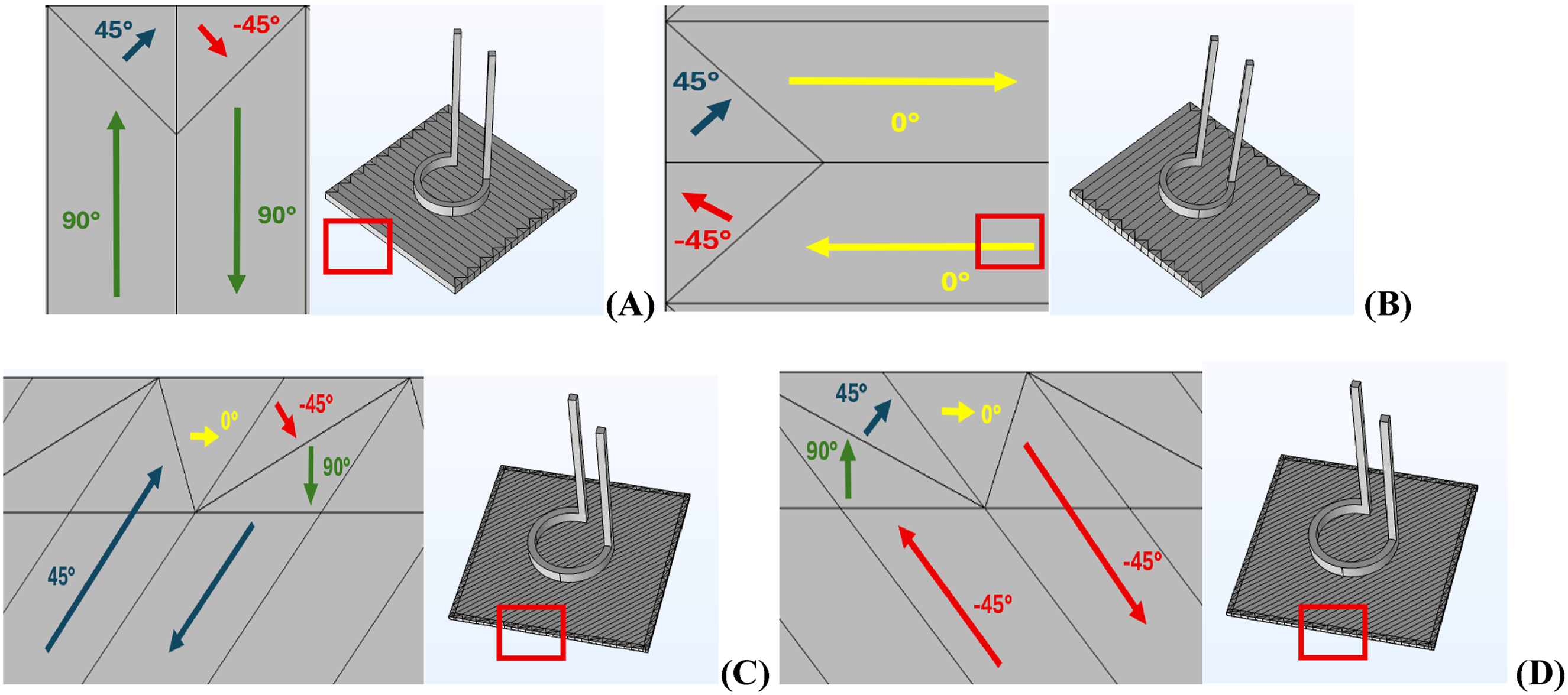
Anisotropic material properties
To capture the anisotropic behavior of CFRP laminates, electrical and thermal conductivities were defined as second-order tensors. In the local material coordinate system, the tensors were: where x is aligned with the fibre direction, y is transverse in-plane, and z is through the thickness. Representative conductivity values were selected from the ranges reported in the literature to reflect the intrinsic anisotropy of CCF σx = 8000 S/m, σy = 10 S/m and σz. = 3–11 S/m, kx = 2.5 W/m, and ky = 0.42 W/m and kz = 0.3 W/m.5,9,16,17,31,32,36,37 A longitudinal electrical conductivity of σx = 8000 S/m (kx = 2.5 W/m) was chosen as a conservative value within the reported fibre-direction range, while σy = 10 S/m (ky = 0.42 W/m) and σz = 3 S/m (kz = 0.3 W/m) were selected to reflect the lower electrical transport in the transverse and through-the-thickness directions due to inter-ply interfaces and contact resistance. Similarly for values of thermal conductivity. All conductivities were assumed to be constant and temperature-independent over the investigated temperature range. The conductivity values adopted in this work originate from studies on consolidated continuous carbon fibre laminates. In the absence of comprehensive electrical conductivity data for additively manufactured continuous fibre laminates, these values were used as first-order approximations. For plies with in-plane rotation (e.g., ±45°, concentric and circular), tensors were transformed into the global coordinate frame using equation (2)
38
:

For the circular layup, the same tensor rotation formulation described in (2) was employed to obtain the locally rotated conductivity tensor

The rotation matrix
Post-processing and data analysis
Post-processing involved comparing thermal images obtained from the infrared camera to the temperature distribution predicted by COMSOL. The spatial temperature distribution was qualitatively compared using image overlays and thermal profile alignment. Quantitative evaluation was performed by calculating the average of the maximum temperatures obtained across three experimental repeats for each design. These values were compared to the corresponding peak temperatures predicted by simulation to assess model accuracy and to evaluate the relative performance of the circular, concentric, and QI fibre designs in terms of thermal intensity and uniformity.
Experimental setup
The induction heating tests were conducted using a circular copper coil, it was powered by a Ceia Powercube 45/900 generator, controlled via a Master Controller v3+ unit. The coil was internally cooled using a TAE Evotech water chiller to maintain stable operating temperatures throughout testing. The coil was positioned 2 mm above the sample, and each sample was placed on a custom additively manufactured holder to ensure consistent support and alignment (Figure 5). The generator operated at 40% power and a frequency of 1.046 MHz. Heating was triggered using a foot pedal, and the on-time was 1 s. The experimental set-up for induction welding and capturing the thermal image of each sample.
A Testo 883 thermal camera, with emissivity set to 0.94, was aimed at the underside of the sample to capture the thermal response. 39 This emissivity value was selected based on reported infrared emissivity values for carbon fibre reinforced polymer surfaces and was verified through preliminary calibration against contact temperature measurements.40,41,42 Thermal images were acquired approximately 3 s after triggering due to camera stabilisation requirements, corresponding to 1 s of active heating followed by approximately 2 s of cooling. Measurements at 1 s would allow a more direct assessment of heating behaviour and model accuracy and are identified as a priority for future experimental work. Experimental infrared images are cropped to the sample surface and colour-scaled using the minimum and maximum temperatures measured on the sample only. Background regions captured by the thermal camera are excluded from the displayed temperature range. A thermal image was recorded 2 s after the end on time. Samples were allowed to cool to ambient conditions between consecutive trials to prevent cumulative thermal effects. The initial temperature before each test was recorded using the thermal camera and verified with an infrared thermometer, confirming a consistent room temperature of 19 ± 1°C. All reported experimental values represent the average of repeated measurements (two replicate samples with three trials each), unless otherwise stated. Experimental thermal images were acquired approximately 3 s after the trigger event due to camera stabilisation requirements, corresponding to 1 s of active heating followed by approximately 2 s of cooling.
Comparisons between experimental and simulated data were made in terms of the temperature rise (ΔT = Tpeak − Tinitial) to ensure consistency across measurements and to account for small variations in starting temperature.
Results
Model validation using UD layups
Figure 6 illustrates the thermal response of the simulated UD configuration without the mesostructure edge detail (A, B, C, D), with the mesostructure included (A’, B’, C’, D’) and the experimental response (A’’, B’’, C’’, D’’). Table 1 summarises the maximum temperatures and corresponding temperature rises (ΔT) obtained from COMSOL simulations at 1 s and 3 s, together with experimental peak temperatures extracted from infrared images recorded 2 s after the end of the heating cycle, for all samples. For numerical results, ΔT is calculated relative to an initial temperature of 20°C, while for experimental results ΔT is calculated relative to an initial sample temperature of approximately 19°C. The models without mesostructure produced centralised heating along the fibre direction, with a little heating with a peak temperature of 20.5°C. The model, including the mesostructure, exhibited edge-focused heating, with a heating of a peak temperature of 22.86°C, which closely corresponded to the experimental data. These results demonstrate that 3D-printing-induced fibre mesostructure significantly influences local current pathways and temperature distribution; therefore, all subsequent models incorporated this feature. Simulated and experimental temperature distributions for UD CFRP laminates with different fibre orientations. For each orientation, three columns are shown. The Thermal images A, B, C, D presents simulations performed in COMSOL without mesostructural turning effects. The thermal images a’, b’, c’, d’ shows simulations including mesostructural fibre turning effects. The thermal images A”, B”, C”, D” presents the corresponding experimental images. (A, A’, A’’) correspond to fibre orientations of 90°, (B, B’, B’’) correspond to fibre orientations of 0°, (C, C’, C’’) correspond to fibre orientations of +45°, and (D, D’, D’’) correspond to fibre orientations of −45°. All images are shown at 3 s. Colour scales are selected per configuration to allow clear visualisation of temperature distributions while enabling qualitative comparison between simulation and experiment. Maximum temperatures for UD CFRP laminates used for model validation. Numerical ΔT values are calculated relative to an initial temperature of 20°C. Experimental ΔT values are calculated relative to an initial sample temperature of 19°C.
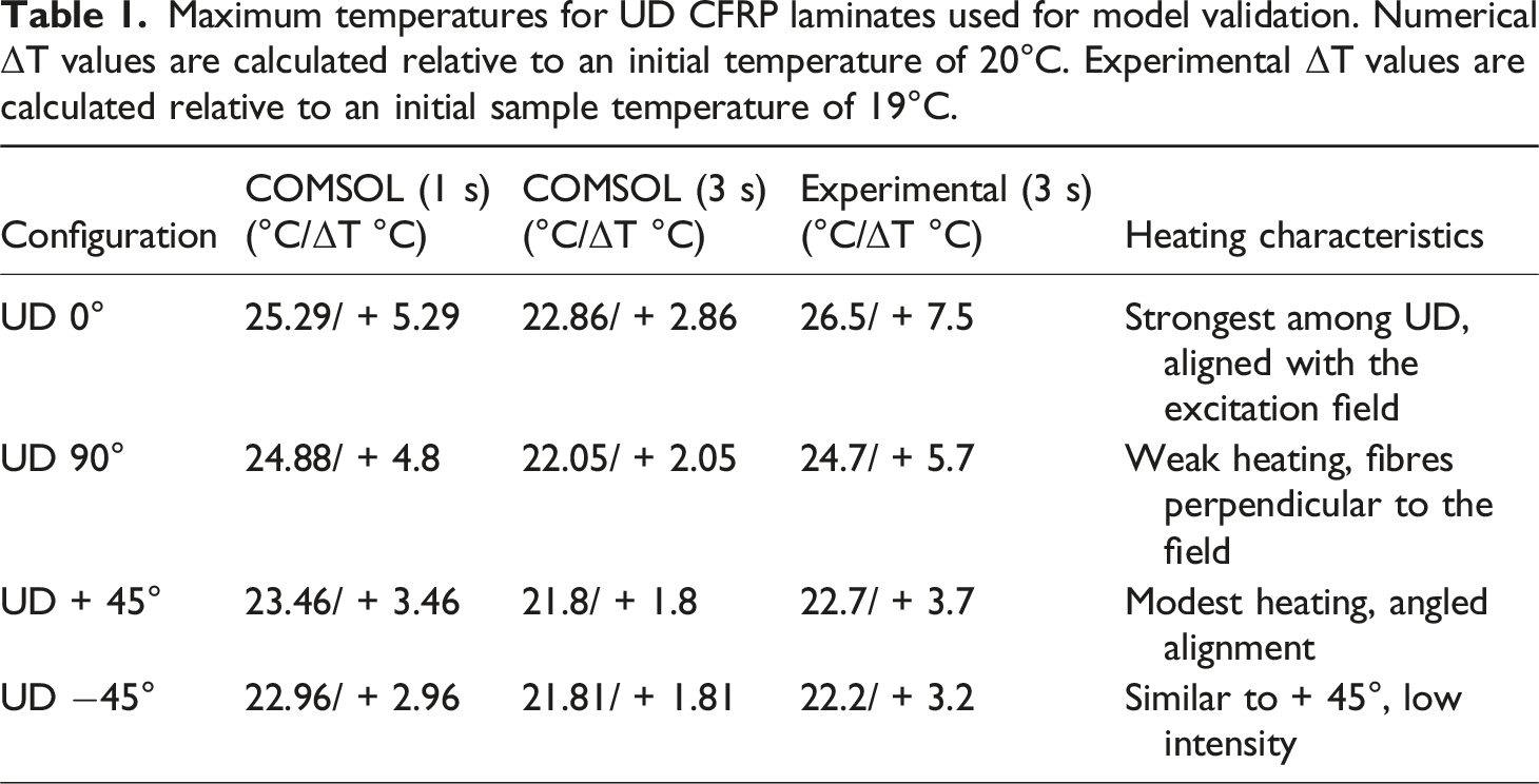
The +45° and −45° orientations exhibited modest temperature rises, with both simulation and experiment confirming that heating was concentrated along the diagonal axis defined by the fibre direction. For the +45° sample, the simulated peak temperature reached 23.46°C at 1 s and 21.8°C at 3 s, whereas the experimental value was 22.7°C (at 3 s). Similarly, the −45° configuration showed simulated peak temperatures of 22.96°C at 1 s and 21.81°C at 3 s, compared with an experimental temperature of 22.81°C. The temperature increase across most of the sample surface was nearly uniform, with an average rise of approximately 2°C.
The 0° and 90° UD samples exhibited more pronounced and localised heating along the edges. In the 0° configuration, strong heating was observed along the horizontal edges, with simulated temperatures of 25.29°C at 1 s and 22.86°C at 3 s, compared with an experimental temperature of 26.5°C. Similarly, as expected, the 90° configuration showed vertically oriented hot regions, with COMSOL predicting 24.88°C at 1 s and 22.05°C at 3 s, whereas the experimental temperature reached 24.7°C.
The agreement in trends, temperature distributions and maximum temperatures between simulated and experimental data confirms the accuracy of the COMSOL model, validating its use for investigating more complex susceptor geometries.
Evaluation of fibre architecture performance
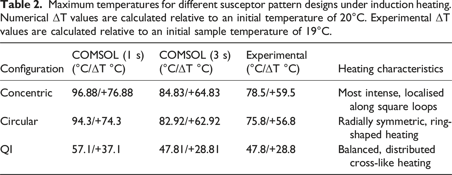
The concentric layup exhibited the highest intensity, with localised heating along the inner loops and peak simulated temperatures of 96.88°C at 1 s and 84.83°C at 3 s, compared with an experimental value of 78.5°C. This architecture is particularly effective for precision bonding along square or rectangular bond lines, including structural reinforcements or embedded susceptor zones.5,9,29
The circular layup model produced radially symmetric, ring-shaped heating, reaching 94.3°C at 1 s and 82.92°C at 3 s, compared to an experimental temperature of 75.8°C, far exceeding the UD cases. This confirms that continuous circular fibre routing efficiently guides eddy currents, promoting strong and uniform heating across the central zone. This configuration is well-suited to circular or annular joints, such as pipe collars, composite rings, or aerospace flange bonding.
The QI layup, based on a stacking sequence, exhibited a distributed cross-like heating pattern. Multiple fibre orientations enabled current flow along different pathways, yielding a more uniform but less intense response compared to circular and concentric designs. The QI layup generated a balanced, cross-shaped heating pattern, achieving 57.1°C at 1 s and 48.81°C at 3 s in simulation and 47.8°C experimentally. The balanced distribution is advantageous for broad-area heating, panel joining, or repair operations where uniform temperature is prioritised over peak intensity.5,9,29
The temperature distribution of the QI layup exhibited the most notable discrepancies between simulation and experiment. While the COMSOL model predicted relatively uniform central heating, experimental results revealed additional thermal concentration along the edges and diagonals. Such behaviour has been reported in the literature and is characteristic of QI laminates, where inter-ply electrical interactions and current redistribution between differently oriented plies play a dominant role in defining the heating pattern.43,44
The present model assumes homogenised ply conductivities and idealised interlaminar electrical contact. While this approach is adequate for unidirectional laminates, where edge effects are dominated by in-plane current confinement within individual plies, it limits the model’s ability to capture the behaviour of the QI configuration. In QI laminates, the alternating 0°, ±45°, and 90° ply orientations promote enhanced inter-ply current redistribution, making edge heating sensitive to interlaminar electrical interactions such as ply-to-ply contact resistance and orientation-dependent current transfer, particularly within inner plies where through-thickness transport is limited. These effects are not explicitly resolved in the present model, leading to a more uniform through-thickness current distribution and a central temperature maximum that does not fully match the experimentally observed edge- and surface-dominated heating. At this stage, these explanations should be regarded as physically motivated hypotheses rather than a definitive resolution. Addressing this limitation will require dedicated future work involving explicit inter-ply electrical interfaces and improved through-thickness modelling.
Impact of spatially varying fibre orientation on induction heating behaviour
In induction welding of CFRPs, the required temperature typically lies between 220 and 300°C, depending on the polymer matrix (e.g., PEEK 343°C, PPS ≈ 285°C, PEI ≈ 260°C).4,10 The simulated peak temperatures in this study are lower than reported welding thresholds, which is expected given that only 40% of the generator power was used. Nevertheless, the simulations reproduce realistic heating trends observed in experimental setups, namely the relative heating intensity across fibre architectures, which consistently follows the sequence concentric > circular > QI > UD. This agreement between simulation and experiment demonstrates that the model accurately captures the dominant induction heating mechanisms associated with different fibre layups.5,12 This indicates that while the modelled configurations capture the qualitative eddy-current distribution and relative heating trends associated with different fibre architectures, achieving weld-quality temperatures would require higher input power or improved susceptor–coil coupling. Quantitative discrepancies in peak temperature, particularly for highly localised designs such as the concentric pattern, highlight the influence of idealised modelling assumptions and indicate that further refinement is required for accurate amplitude prediction. In addition, the heating duration in this study was limited to 1 s. If the susceptor were subjected to the magnetic field for a longer period or higher amplitude, the temperature would continue to rise as long as inductive heat generation exceeds heat losses due to conduction, convection, and radiation. Under sustained excitation, the temperature would increase until a steady-state condition is reached where generated power balances thermal losses. Consequently, weld-quality temperatures suitable for high-performance thermoplastic matrices could be achieved through longer heating times, higher generator power levels, or enhanced coil–susceptor coupling, all of which are compatible with the modelling framework presented in this work.
Across all cases, the relative heating intensity followed the sequence: concentric > circular > QI > UD. This ordering is governed by the ability of each fibre architecture to support continuous eddy-current loops that are favourably aligned with the circumferential electric field generated by the circular induction coil. Architectures such as concentric and circular layouts provide long, closed current paths with minimal directional disruption, which promotes efficient current circulation and enhanced Joule heating. In contrast, QI and UD layups introduce frequent changes in fibre orientation or limit current continuity, reducing the effective induced current magnitude and heating intensity. Similar coil–layup coupling effects and current-path-driven heating behaviour have been widely reported in induction heating and welding studies of CFRP laminates.5,10
It should be noted that this performance sequence is specific to the circular coil geometry employed in this work. Different coil designs would generate distinct electric-field distributions and orientations, which could modify the relative heating efficiency of the investigated fibre architectures, as discussed in previous studies.1,45 Nevertheless, the present results demonstrate how fibre layup can be strategically tailored to exploit a given coil geometry for targeted induction heating and composite joining applications.
The comparison of temperatures at 1 s and 3 s enables evaluation of the short-term cooling process following the 1 s induction heating phase. This cooling analysis is based on numerical results, as experimental temperature–time cooling curves were not directly collected in the present study due to the short heating duration and the focus on peak temperature measurements. Across all configurations, the simulated temperature decreased during the 2 s post-heating interval, corresponding to an average reduction of 10–15% from the peak values. The most substantial cooling was observed in the circular, concentric, and QI layups, which exhibited the highest initial temperatures and the largest surface areas promoting convective heat losses (Figure 7). In contrast, the UD configurations showed minor cooling ranging between 2 and 3°C. Although the UD 0° and UD +45° configurations reached similar peak temperatures at the end of heating, the UD 0° sample exhibited a smaller temperature decrease during the cooling phase. This behavior arises from differences in the spatial distribution of heat rather than from differences in boundary conditions, which were identical for all models. In the UD 0° configuration, induced currents are strongly aligned with the fibre direction, resulting in a more localised heating pattern and reduced lateral heat spreading. This localisation limits the effective area available for convective heat loss during the early cooling phase. In contrast, the UD +45° configuration produces a more distributed temperature field, increasing the effective heat exchange area and leading to a faster apparent cooling rate (Table 2). The numerical model captures the short-term temporal decay observed between the simulated temperature fields at 1 s and 3 s following the heating phase.21,46,47 Simulated (left row (A, A, C)) and experimental (right row (A’, B’, C’)) temperature distributions for design of the proposed susceptors with (A, A’) circular, (B, B’) concentric and (C, C’) QI Simulated (left column) and experimental (right column) temperature distributions for the proposed susceptor designs: (A) circular, (B) concentric, and (C) QI. The time-dependent thermal simulation spans 3 s (0.1 s time steps), consisting of 1 s of induction heating followed by 2 s of cooling. Simulated temperature fields are shown at t = 3 s, corresponding to the time at which the experimental infrared images were recorded (2 s after the end of heating). Maximum temperatures for different susceptor pattern designs under induction heating. Numerical ΔT values are calculated relative to an initial temperature of 20°C. Experimental ΔT values are calculated relative to an initial sample temperature of 19°C.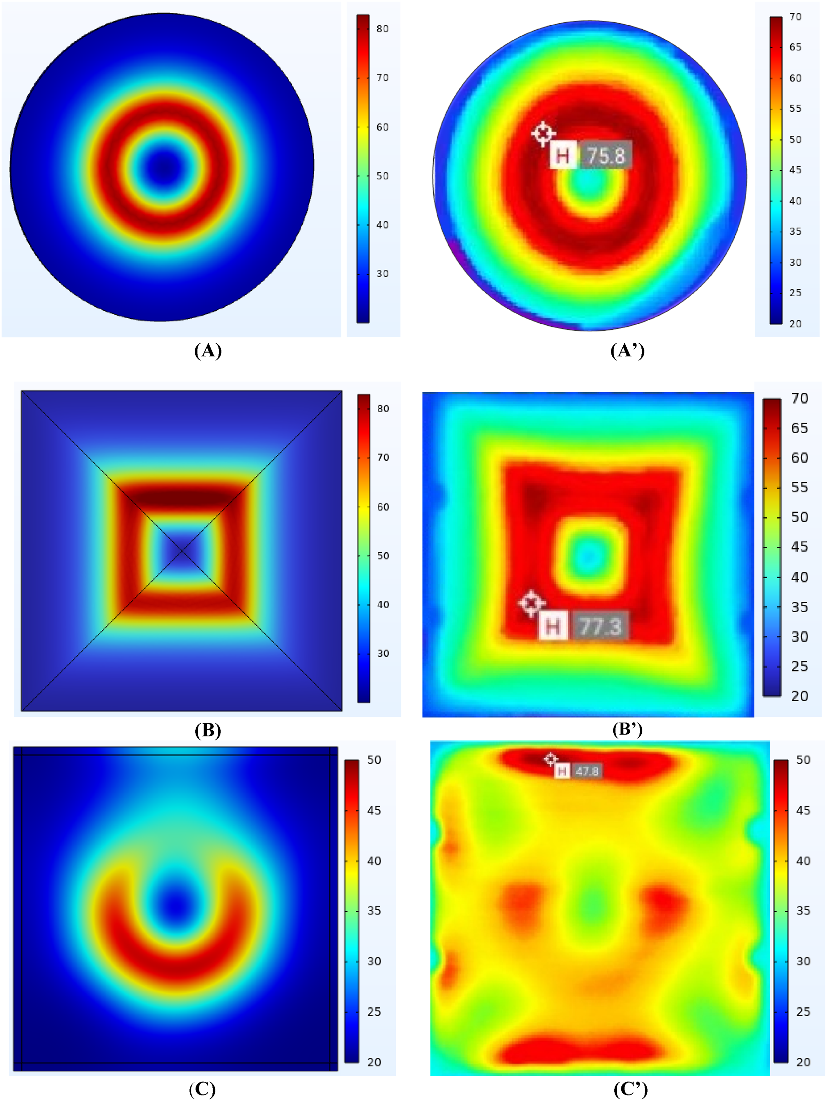
Conclusion
This study demonstrates the feasibility of engineering fibre architecture as an intrinsic susceptor mechanism in CFRT thermoplastic composites for induction welding. A combined numerical–experimental framework was developed to investigate the influence of fibre layout and 3D-printing-induced mesostructure on induction heating behaviour.
Model validation was first established using UD laminates with 0°, ±45°, and 90° fibre orientations. For these configurations, very good agreement was obtained between COMSOL Multiphysics simulations and experimental infrared thermography in both heating patterns and peak temperature evolution. This agreement confirms that the electromagnetic–thermal model reliably captures the dominant eddy-current mechanisms and anisotropic heating behaviour in fibre-aligned architectures, providing a robust foundation for analysing more complex fibre layouts.
Building on this validated framework, three fibre-steered susceptor architectures; circular, concentric, and QI were examined. The results show that fibre architecture and mesostructural steering introduced by the 3D printing process play a decisive role in governing current pathways and temperature distributions. Among the investigated designs, the concentric architecture produced the most intense and localised heating, making it suitable for applications requiring focused thermal zones, such as structural reinforcements or embedded functional layers. The circular layout generated radially symmetric heating and is well suited for ring-shaped bonding interfaces, including pipe collars or aerospace flanges. The QI configuration distributed heating across multiple fibre directions rather than concentrating it along a single dominant path. Although this response exhibited pronounced spatial variations and edge effects and cannot be considered homogeneous, it may be advantageous for applications such as panel repair or large-area bonding where avoiding extreme local hotspots is prioritised over strict temperature uniformity. Across all cases, the relative heating intensity followed the sequence: concentric > circular > QI > unidirectional.
The agreement in heating trends between simulation and experiment confirms that fibre steering can be used to control induction heating intensity and spatial distribution without relying on metallic susceptors. However, larger discrepancies were observed for the circular, concentric, and QI configurations compared to the UD cases. These deviations arise from increased geometric complexity, enhanced edge effects, and inter-ply current redistribution, which amplify sensitivity to interlaminar contact resistance and temperature-dependent material behaviour not fully captured by the present model.
Overall, the results highlight the potential of fibre-architecture-based susceptors for multifunctional composite systems, where fibre layouts influence not only mechanical performance but also controlled thermal actuation. Future work will focus on improving the quantitative accuracy of the thermal model through refined inter-ply electrical interactions, contact resistance, and temperature-dependent material properties. With improved model fidelity, this approach will be extended to multi-material assemblies, complex three-dimensional geometries, and joint-strength evaluation under service conditions. Fibre-steered susceptors therefore represent a lightweight, structurally integrated, and sustainable alternative to conventional metallic inserts for advanced thermoplastic composite manufacturing.
Footnotes
Declaration of conflicting interests
The authors declared no potential conflicts of interest with respect to the research, authorship, and/or publication of this article.
Funding
The authors disclosed receipt of the following financial support for the research, authorship, and/or publication of this article: This research is funded by the Department of Business, Enterprise, and Innovation and administered by Enterprise Ireland under the Disruptive Technologies Innovation Fund, Mi-Drone Project (Ref:). The authors would also like to acknowledge the financial support from Science Foundation Ireland through the MaREI Research Centre for Climate, Energy and Marine (Grant no. 12/RC/2302_2), I-Form Centre for Advanced Manufacturing (16/RC/3872 and 21/RC/10295_P2), and Enterprise Ireland through Construct Innovate (TC-2022-0033).