
Abstract
CFRP/Ti6Al4V stacks are widely employed in aerospace, automotive and marine applications owing to their superior properties. However, machining these stacked structures pose challenges due to the intrinsic difference in the mechanical properties of CFRP and Ti6Al4V. Such difference can induce distinct failure mechanisms and chip formation processes compared to those observed in individual materials. This paper presents an explicit finite element (FE) modeling to predict the cutting forces and analyze the induced damage during the orthogonal cutting process. The proposed FE model is validated using available experimental data for separate CFRP and Ti6Al4V conditions before being applied to simulate the cutting behavior of CFRP/Ti6Al4V stacks. The effects of fiber angles, cutting sequences and cutting parameters on the cutting performance and damage mechanism of CFRP/Ti6Al4V stacks are investigated in detail. This work provides insights into the cutting behavior of CFRP/Ti6Al4V stacks and facilitates the optimization of machining process for such composite system.
Introduction
CFRP/Ti6Al4V stacks are composite materials consisting of thin metal layers and CFRP layers arranged in a specific sequence. 1 CFRP offers many advantages, including high specific modulus and strength, exceptional fatigue properties and excellent corrosion resistance. However, it is also characterized by drawbacks such as high brittleness, unstable failure, and high cost. In contrast, Ti6Al4V displays good isotropy, consistent plasticity, and high strength. CFRP/Ti6Al4V stacks effectively address the limitations of single-phase materials and demonstrate superior mechanical properties compared to individual materials.2-4 As a result, CFRP/Ti6Al4V stacks have been widely employed in aerospace, automotive, marine, and other high-tech industries. 5
Components made of CFRP/Ti6Al4V stacks often need to be assembled with other components using bolting and riveting techniques. Drilling is a widely used method for creating connection holes, and it is essential to adhere to specific accuracy and surface integrity requirements during this process. However, CFRP and Ti6Al4V present challenges in machining due to their classification as difficult-to-machine materials. The intrinsic difference in the mechanical properties can result in machining defects during the cutting process.6-8 CFRP exhibits anisotropic properties at macroscopic scale and consists of fibers, matrix and interface at microscopic scale, which are prone to defects like fiber pull-out, matrix cracking and interface debonding. 9 Cutting parameters also affect the machining performance of composite structures.10,11 On the other hand, Ti6Al4V generates high cutting heat and cutting force during the cutting process. 12 For CFRP/Ti6Al4V stacks, the chips produced from the cutting material will affect the cutting process of other phase material, and the material damage occurring in the machining will cause performance decrease of CFRP/Ti6Al4V stacks, ultimately reducing their service life. 13 Therefore, it is necessary to investigate the damage behavior of CFRP/Ti6Al4V stacks during the cutting process and analyze the corresponding cutting performance and failure mechanisms.
In recent years, the drilling performance of CFRP/Ti6Al4V stacks has been concerned by researchers. An et al. 14 examined the effect of drilling sequence on the cutting performance of CFRP/Ti6Al4V stacks. It was discovered that commencing the drilling process from the Ti6Al4V layer yields improved accuracy. However, in practical industrial production, the preferred drilling sequence is from CFRP to Ti6Al4V, as it results in minimal delamination damage. Luo et al. 15 conducted a study on the relation between the thrust force and structural deformation during the drilling of low-stiffness CFRP/Ti6Al4V stacks. They also found that the presence of interlayer gap and high feed rate result in increased interface damage. However, applying pressure to the stack surface through a clamping foot proves effective in reducing the interface damage. Moreover, to gain a more comprehensive understanding of the stacked cutting mechanism, Xu et al.16,17 conducted orthogonal cutting tests on stacked materials. These tests aimed to enhance the analysis of the cutting mechanism involved in drilling. The results indicated that the cutting sequence consistently influenced the two-phase cutting forces in both orthogonal cutting and drilling scenarios. Furthermore, it was concluded that the fiber angle played a vital role in determining the cutting performance of stacked materials.
Orthogonal cutting is recognized as an effective method for studying the material cutting mechanism in complex drilling process. The orthogonal cutting process of CFRP and Ti6Al4V has been extensively investigated. For CFRP, there are two modeling approaches: macroscopic and microscopic modeling. Macroscopic modeling treats CFRP as a homogeneous material and employs macro criteria to determine the material failure. However, it fails to capture the specific failure modes of fibers and matrix. On the other hand, microscopic modeling is based on the material configuration of CFRP, taking into account the fibers, matrix, and interface.18,19 An et al. 20 and Wang et al. 21 conducted orthogonal cutting tests to examine the effects of various cutting parameters on the mechanical characteristics, such as cutting force and specific cutting energy, during the material removal process of UD-CFRP. Cheng et al. 22 developed a micro-scale fracture model for micro cutting of UD-CFRP to understand the deformation mechanism and predict the cutting force. The proposed model incorporates thermal-mechanical coupling and captures the failure modes of fibers, matrix, and interface utilizing a micro-level representative volume element (RVE). In addition, Su et al. 23 phenomenally studied the influence of cutting speed on the micro failure of CFRP by FE simulation based on the strain-rate dependent properties of resin combining with the subsurface scanning electron microscopy (SEM) morphology.
The cutting mechanism of stacks cannot be accurately described by studying the cutting behavior of individual materials due to the interaction between the two phase materials. Regarding this, Xu et al. 24-26 developed a 2D macroscopic orthogonal cutting model of CFRP/Ti6Al4V stacks to study the effect of cutting sequence on the cutting response. The analysis focused on chip formation, surface morphology, subsurface damage, and interfacial delamination of the stacked layers. It was found that the superior machining quality could be achieved using the CFRP-to-Ti6Al4V cutting sequence, and in the actual machining process, a combination of high cutting speed and low feed rate was desirable. Li et al. 27 developed a 3D microscopic FE model for oblique cutting of CFRP/Ti stacks to examine the chip formation process and subsurface damage and interface defect formation mechanisms. Jia et al. 28 used a 3D macroscopic oblique cutting model to study the effects of cutting parameters and stacking sequence on subsurface damage. Besides, Boutrih et al. 29 analyzed the effect of fiber angle, depth of cut and cutting speed on delamination damage.
Currently, the research on the simulation of orthogonal cutting for CFRP/Ti6Al4V stacks is relatively limited. Limited studies have employed 3D microscopic approaches to investigate the influence of fiber orientation on the cutting mechanism in stack models. Furthermore, there is a lack of analyses examining the effect of cutting parameters on cutting performance using this approach. It is necessary to further analyze the effect of cutting parameters on the cutting performance and damage mechanism of these stacks, as well as the interaction between the multi-material systems. On the other hand, the utilization of a 3D micro model allows for more accurate and intuitive visualization of the interactions between the two phases during the cutting process, as well as the fracture of fibers and matrix failure. The objective of this work is to develop a 3D FE model to investigate the effect of fiber angle, cutting sequence, and cutting parameters on the cutting performance of CFRP/Ti6Al4V stacks. The maximum stress criterion is employed to predict the fiber failure, the Johnson-Cook model is used to identify the failure of Ti6Al4V and matrix, and the bilinear traction-separation model is utilized to simulate the delamination and debonding occurring at the CFRP-Ti6Al4V interface and fiber-matrix interface. The cutting process of CFRP/Ti6Al4V stacks is simulated and the material damage mechanisms under various fiber angles and cutting parameters are analyzed in detail. This numerical work contributes to a better understanding of the cutting mechanism for CFRP/Ti6Al4V stacks and provides a solid foundation for future research on such composite system.
Damage constitutive model
The FE model of CFRP/Ti6Al4V stacks includes three phases: CFRP (including fiber, matrix, and fiber-matrix interface), Ti6Al4V, and CFRP-Ti6Al4V interface. Each material is assigned a specific constitutive model to accurately represent its mechanical behavior.
Constitutive model of carbon fiber
The linear elastic constitutive relation of transverse isotropic fiber can be described by
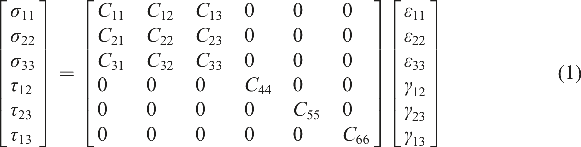
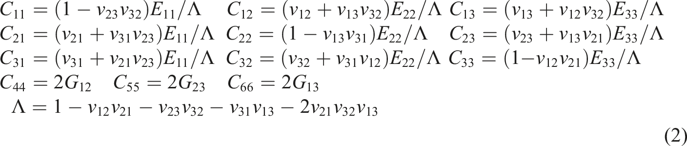
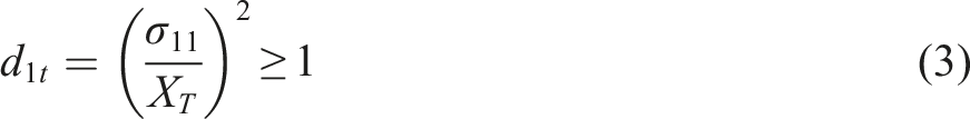
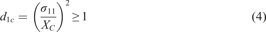
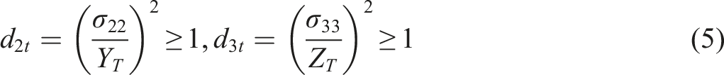
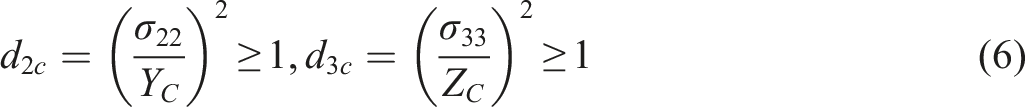
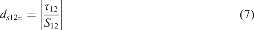
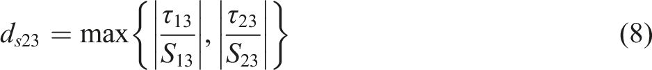
The maximum stress criteria are widely employed to determine the failure of fiber, and if the stress in any direction reaches or surpasses the ultimate strength in that same direction, the fiber will experience brittle failure, leading to the loss of load-bearing capacity.30-32 The maximum stress criteria are as follows. (1) Tensile failure in longitudinal direction (2) Compressive failure in longitudinal direction (3) Tensile failure in transverse direction (4) Compressive failure in transverse direction (5) Shear failure (in plane) (6) Shear failure (out of plane)
Constitutive model of Ti6Al4V and matrix
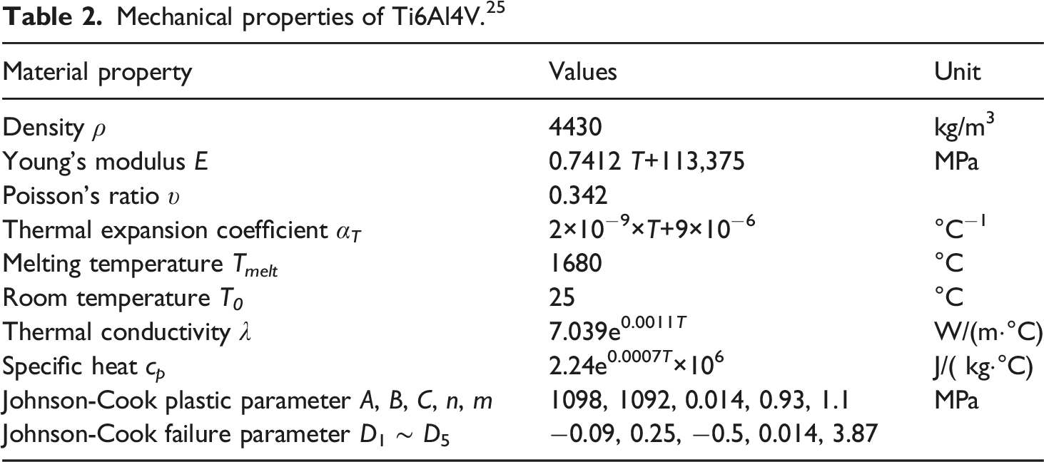
Both Ti alloy and epoxy resin matrix are considered as uniformly isotropic elasto-plastic materials here. The Johnson-Cook model can well describe the effects of temperature and strain rate on the properties of such materials. Johnson-Cook constitutive model can be expressed by
33

During the damage stage, different failure criteria and stiffness degradation schemes are employed for the matrix and Ti6Al4V. The matrix utilizes ductile damage criterion to determine the damage initiation, indicating that damage occurs when the equivalent plastic strain reaches the fracture strain. After damage initiation, energy-based degradation is utilized to progressively reduce the stiffness of the material. On the other hand, Ti6Al4V adopts the Johnson-Cook damage model and displacement failure criterion. The equivalent plastic fracture strain,

Constitutive model of interface
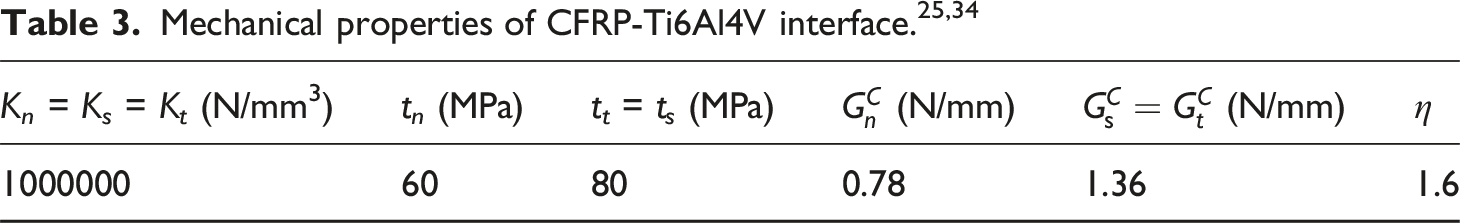
Cohesive elements are incorporated to accurately simulate the delamination and debonding phenomena at CFRP-Ti6Al4V interface and fiber-matrix interface. The cohesive elements follow the cohesive zone model, specifically the mixed-mode bilinear traction-separation constitutive model, namely
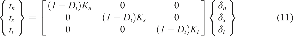
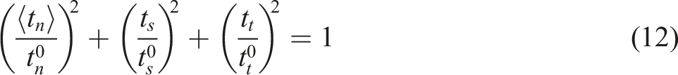
The damage initiation of interface is determined by the quadratic nominal stress criterion, namely
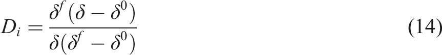
Linear degradation of material properties is implemented based on energy once the damage initiation criterion is met, and the damage variable D
i
is expressed by


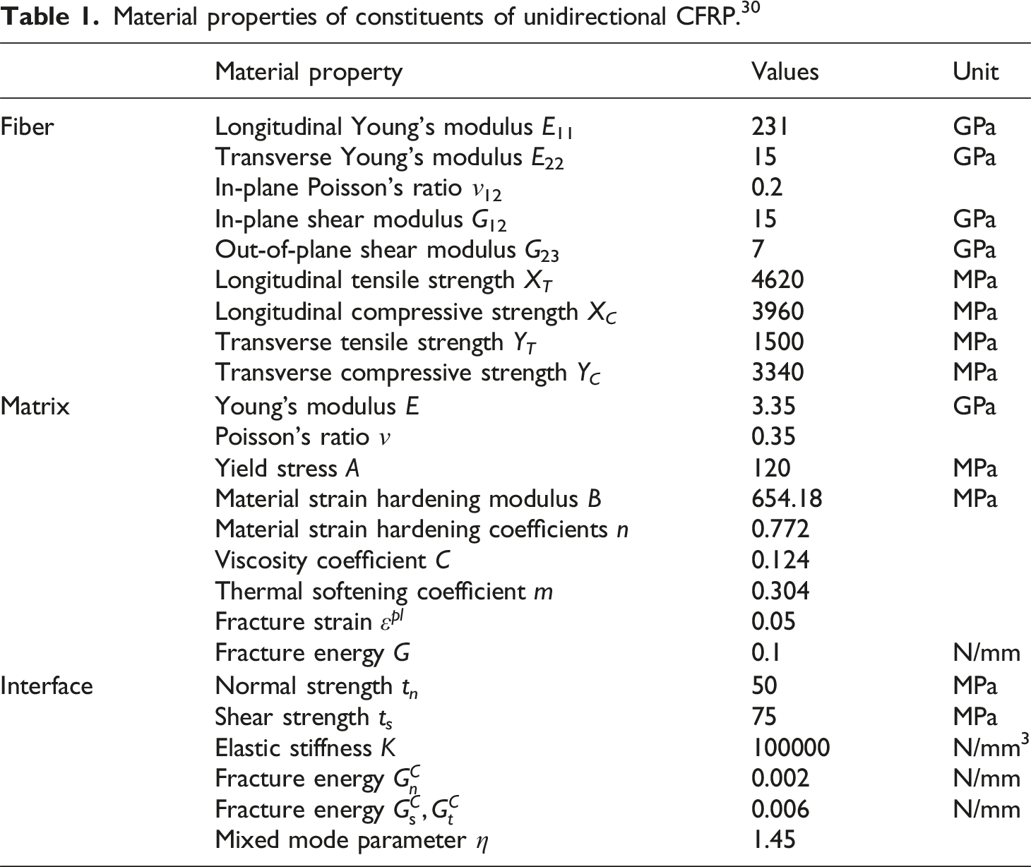
Material properties of constituents of unidirectional CFRP. 30
Mechanical properties of Ti6Al4V. 25
Description of nonlinear FE model
FE modeling
In this section, 3D micro orthogonal cutting FE models are developed, incorporating different fiber angles of 0°, 45°, 90°, and 135°. Distinct material properties are assigned to the fiber, matrix, Ti6Al4V, tool, and interfaces. The fiber angle is measured counterclockwise from the cutting speed direction to the fiber direction. Specifically, the FE model of CFRP/TI6Al4V stacks with 90° fiber is displayed in Figure 1. Micro FE model of CFRP/TI6Al4V stacks with 90° fiber.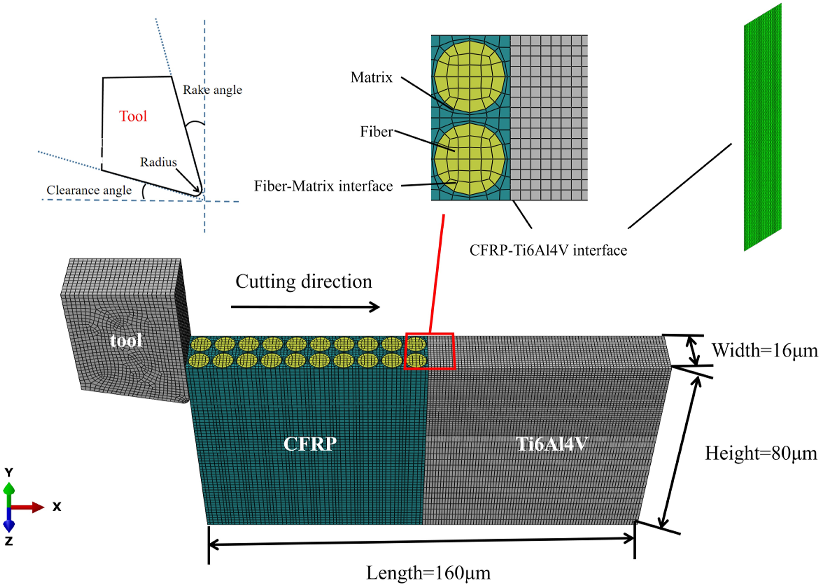
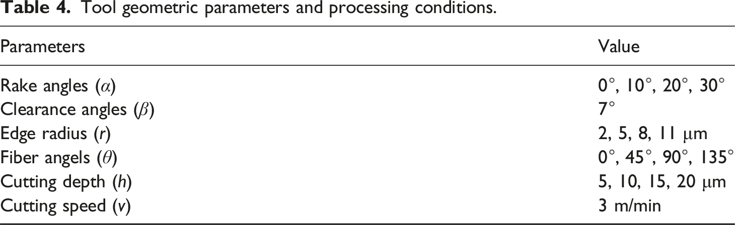
Tool geometric parameters and processing conditions.
In the simulation, the tool cuts the workpiece from the left end, and complete fixed constraints are applied on the bottom and right end of the workpiece to prevent any movement. For the contact interactions between the tool and workpiece, the normal contact is defined as hard contact. Tangential contact is defined as penalty contact to handle frictional effects. The friction coefficient between the tool and CFRP varies depending on the fiber direction: it is 0.2 for fiber angles of 0° and 135°, and 0.5 for other cases. The friction coefficient between the tool and Ti6Al4V is set to 0.4. To establish contact between the tool and workpiece, a node to surface contact approach is adopted, where the tool surface is defined as the main surface and the workpiece nodes serve as the slave surface. Additionally, general contact is enabled to prevent elements from intruding into each other during the simulation.
Verification of proposed model
To validate the single-phase models, the simulation results of the Ti6Al4V and CFRP models are compared with the available experimental data from orthogonal cutting experiments. The CFRP material properties and cutting parameter configurations in Ref. 30 are adopted first. The cutting parameters are defined as: rake angle (α) 10°, clearance angle (β) 11°, edge radius (r) 15 μm, cutting speed (v) 3 m/min, and cutting depth (h) 40 μm.
In Figure 2(a), the cutting forces per unit width are displayed for CFRPs with four different fiber angles. It is observed that the simulation results exhibit a similar trend to the experimental data. Specifically, the cutting forces reach their maximum value when the fiber angle is 90°. This match between the simulation and experimental data validates the accuracy of the cutting force prediction in the simulation model. To verify the chip formation process, the same cutting parameters in Ref.
35
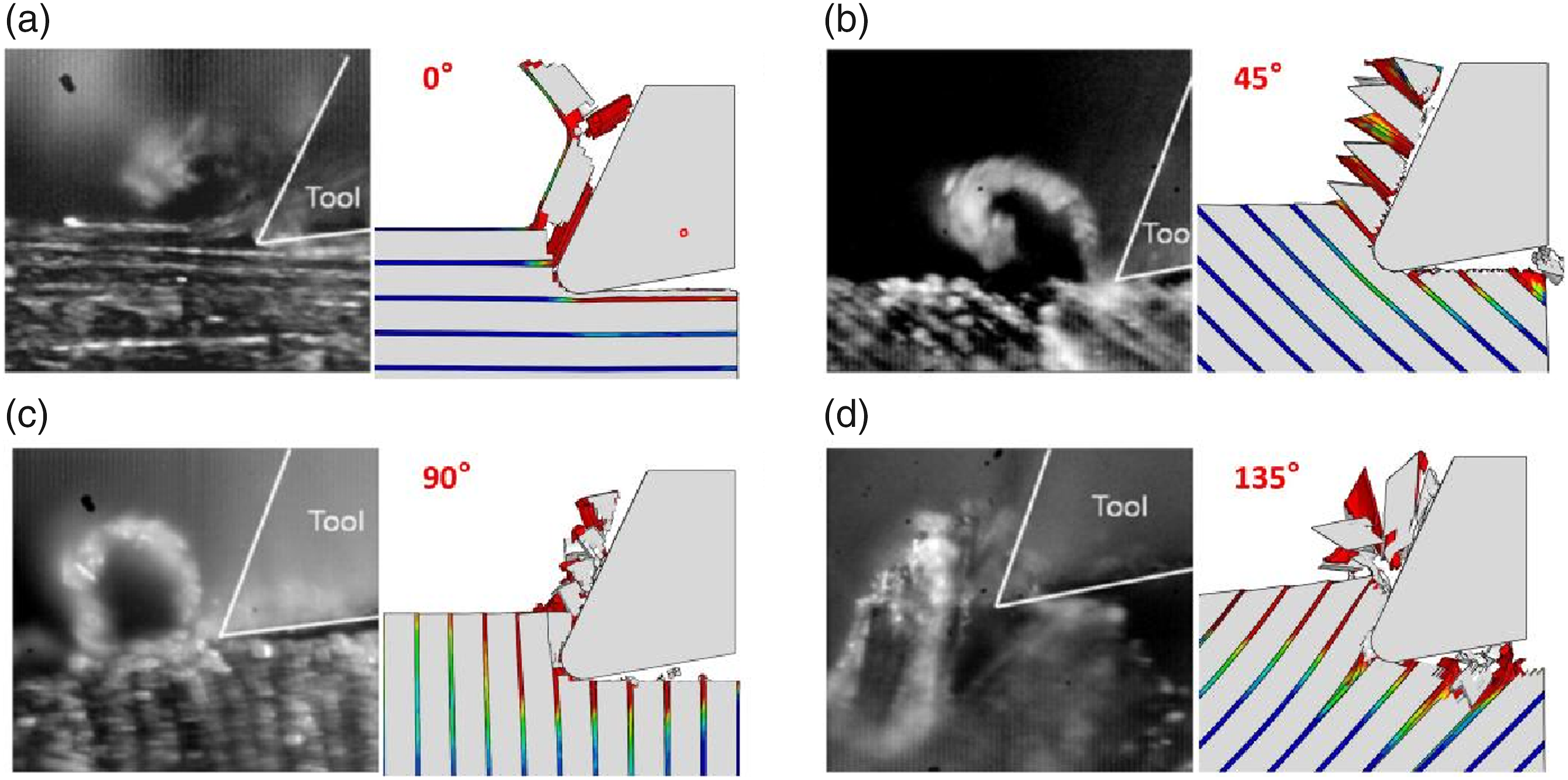
are used, with a rake angle α = 25°, edge radius r = 5 μm and cutting depth h = 15 μm, but the cutting speed v is kept at 3 m/min. Figure 3 illustrates the chip formation process for CFRPs with four different fiber angles. It is evident that the observed chip formation phenomena in both experimental and simulated scenarios are similar. The difference between them can be attributed to the implementation of element deletion strategy. Therefore, this demonstrates the effectiveness of proposed model in simulating the chip formation mechanism for CFRP with varying fiber angles. By combining the results depicted in Figure 2(a) and Figure 3, the validity and reliability of the developed CFRP model can be established. Cutting forces in simulation and experiment of Ti6Al4V and CFRP (a) Cutting forces of CFRP with four different angles (b) Cutting forces of Ti6Al4V at three different cutting depths. Simulation and experiment
35
comparison of cutting process of CFRP with four fiber angles (a) 0° (b) 45° (c) 90° (d) 135°.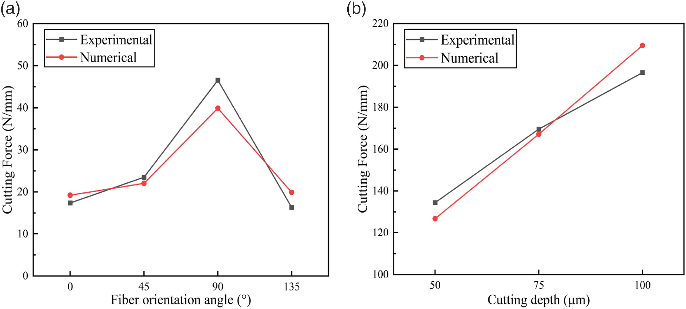
To validate the Ti6Al4V model, the orthogonal cutting experiment data from Ref.25,36 are chosen for comparison. In this experiment, tool rake angle α of 6.5° and edge radius r of 5 μm are utilized. The cutting forces of Ti6Al4V at three different cutting depths are depicted in Figure 2(b). The experimental values are determined by averaging the cutting force results obtained near cutting speed 4 m/min. It reveals a correlation between the cutting force and cutting depth, and a close agreement is observed between the experimental and simulation results. Notably, the cutting force increases as the cutting depth increases. Hence, these results demonstrate the effectiveness of proposed model in accurately simulating the cutting force of Ti6Al4V.
Numerical results and discussions
Given that the numerical models for individual materials have been verified to accurately predict the cutting force and depict the cutting process, they are then employed to investigate the cutting response of CFRP/Ti6Al4V stacks in this section. The effects of different cutting sequences on the cutting performance of CFRP/Ti6Al4V stacks with varying fiber angles are examined. Considering the micro constituent differences of CFRP and the properties differences between CFRP and Ti6Al4V, the cutting mechanisms of such stacks are analyzed by evaluating factors such as cutting force, fiber breaking, matrix failure, and interface debonding. The cutting conditions employed here include cutting depth of 15 μm, cutting speed of 3 m/min, tool rake angle of 0°, clearance angle of 11°, and edge radius of 2 μm.
Cutting force analysis
Cutting force signal analysis
The cutting force simulation results for CFRP/Ti6Al4V stacks under two cutting sequences are presented in Figures 4 and 5. Four fiber angles, namely 0°, 45°, 90°, and 135°, are considered. Based on the changing characteristics of cutting force, the cutting process can be divided into five stages. Stage Ⅰ: stack cut-in, Stage Ⅱ: CFRP cutting, stage III: interface cutting, stage IV: Ti6Al4V cutting, stage Ⅴ: stack cut-out.
37
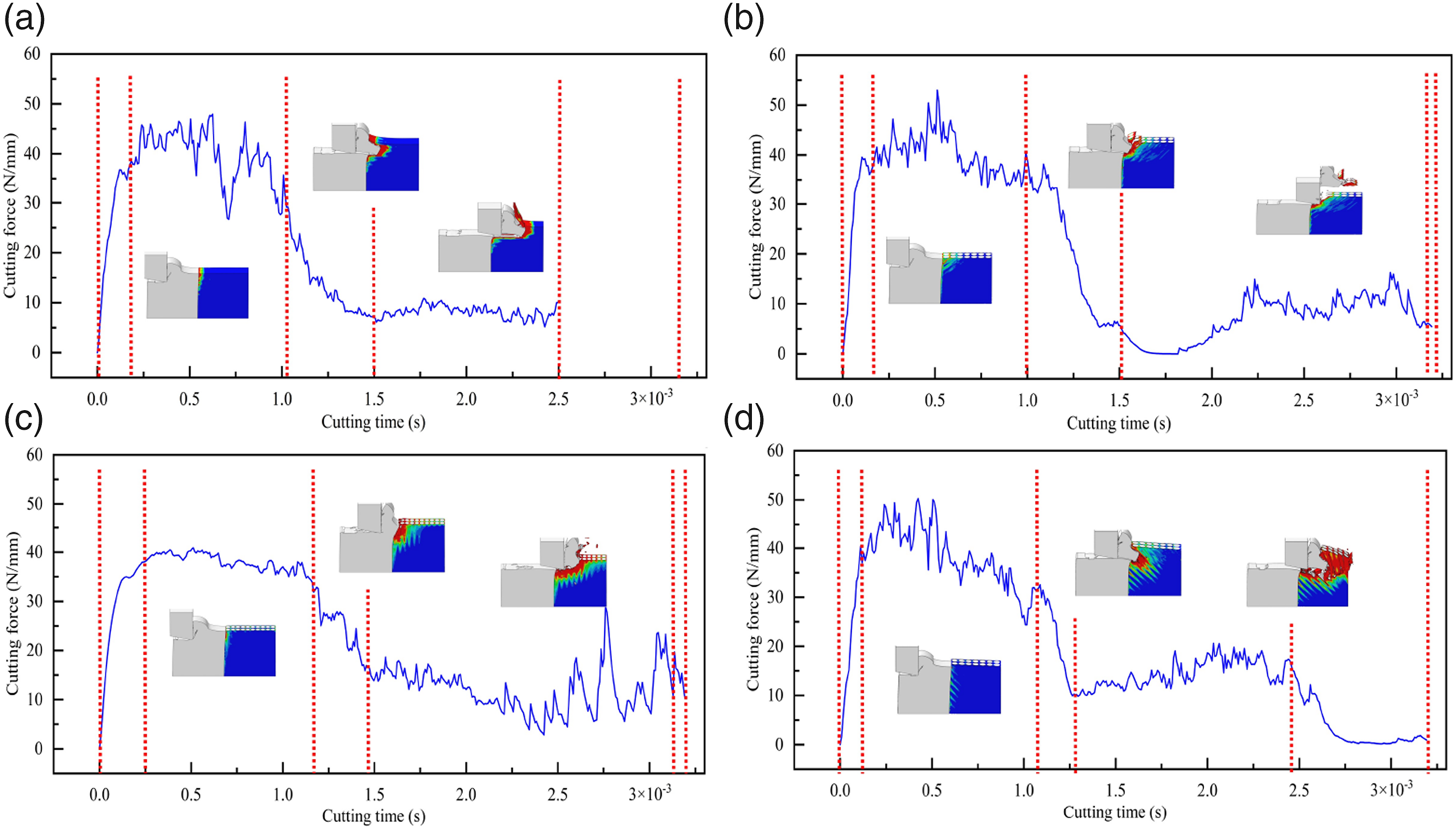
For CFRP/Ti6Al4V stacks, the cutting stages are opposite in these two cutting sequences and each stage is divided by the red dotted lines. In all the examined cases, the cutting stage involving the Ti6Al4V material consistently demonstrates higher cutting forces compared to the other stages. Cutting forces of CFRP/Ti6Al4V stacks with four fiber angles in CFRP-to-Ti6Al4V machining (a) 0° (b) 45° (c) 90° (d) 135°. Cutting forces of CFRP/Ti6Al4V stacks with four fiber angles in Ti6Al4V-to-CFRP machining (a) 0° (b) 45° (c) 90° (d) 135°.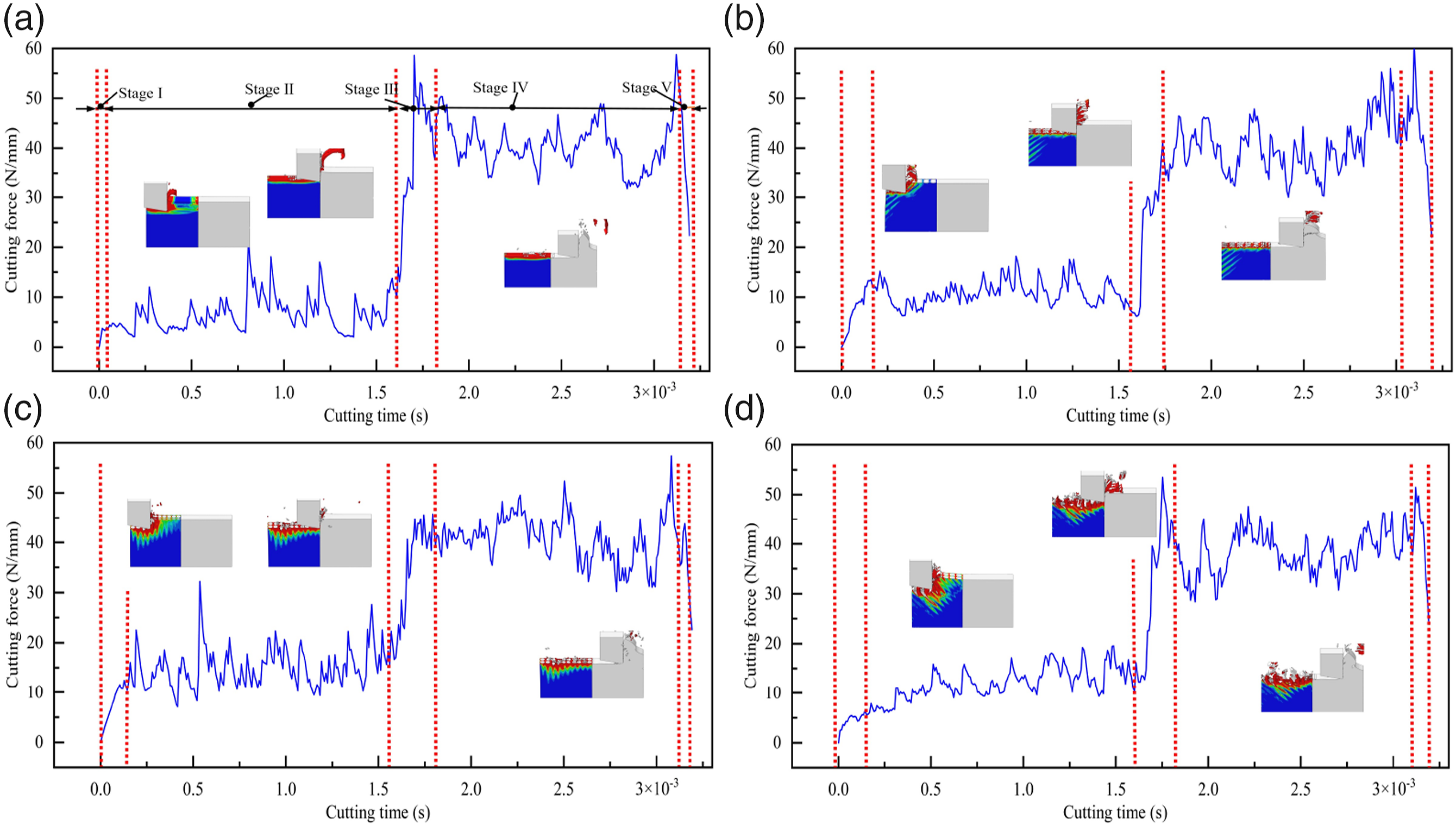
During the CFRP-to-Ti6Al4V cutting sequence, the CFRP/Ti6Al4V stacks with different fiber angles exhibit a similar variation process in cutting force. Initially, the tool gradually cuts into the CFRP material, resulting in a gradual increase in cutting forces. Subsequently, the cutting process enters the CFRP cutting stage where the cutting force stabilizes. Towards the end of the CFRP cutting phase, due to the high hardness of Ti6Al4V, the fiber bending is reduced and the cutting force is slightly increased. A small amount of CFRP chips are involved in cutting Ti6Al4V in front of the tool, and then the CFRP chips are gradually crushed by the tool. Only small deformation of Ti6Al4V occurs during this process. Once the CFRP cutting is complete, the tool gradually cuts into the Ti6Al4V, resulting in a rapid increase in cutting force. Finally, it is worth noting that during the completion of cutting process, the cutting force does not exhibit the slow decline process that occurs with the tool exit due to the fixed constraint at the right end of the workpiece.
During the Ti6Al4V-CFRP cutting sequence, as the tool initially contacts the Ti6Al4V material, there is a rapid increase in cutting force. However, the CFRP material does not provide sufficient support for the Ti6Al4V, leading to a gradual decrease in cutting force. This decrease occurs due to the deformation of the Ti6Al4V phase and the reduction of the uncut length. As the cutting process continues, Ti6Al4V chips gradually form and bend. Interestingly, in this case, the Ti6Al4V chips cut the CFRP material instead of the tool, causing fiber failure during the cutting process. CFRP with a fiber angle of 0° demonstrates a relatively constant cutting force during the CFRP cutting stage. This constancy is attributed to the significant compression failure of fiber during the cutting process, which prevents the Ti6Al4V chips from sliding out. On the other hand, the variation of cutting force for fiber angles of 45° and 90° can be divided into two stages: the Ti6Al4V chips cutting CFRP and the tool cutting CFRP. After cutting for a certain process, the Ti6Al4V chips are pushed by the tool rake angle and are removed along with the CFRP chips. Then the tool starts to cut the CFRP gradually until the cutting is completed. When the fiber angle is 135°, the Ti6Al4V chips are always in front of the tool due to the short cutting distance of the model. However, there is a noticeable trend observed during the cutting process, indicating that the fractured fibers, accompanied by lifting, are gradually removed, leading to a gradual decrease in cutting force. The cutting force curve observed in the simulation during stacked cutting exhibits a similar trend to that obtained from Refs.16,17,29
Analysis of influence of cutting parameters on cutting force
To analyze the impact of the stacked structure on cutting force, the average cutting force between 0.7-1.6 ms and 1.6-2.5 ms is considered as the cutting force for the corresponding phase. Figure 6 illustrates the cutting force for each phase under two different cutting sequences. It is observed that in the CFRP-to-Ti6Al4V sequence, Ti6Al4V exhibits a higher cutting force, which aligns with the findings in the simulation of stacked layers from Ref.
16
The cutting forces of two-phase in this sequence exhibit a similar trend of initially increasing and then decreasing with the fiber angle, reaching their maximum values of 40.99 N and 17.63 N respectively at fiber angle of 90°. This behavior can be attributed to the higher load-bearing capacity of the 90° fibers. Regarding the cutting forces in the CFRP phase, it is observed that the cutting forces are lower at fiber angles of 45° and 90° in the CFRP-to-Ti6Al4V sequence compared to the opposite sequence. This can be attributed to the rapid separation of Ti6Al4V chips from the front of the tool at fiber angles of 45° and 90° in the Ti6Al4V-to-CFRP sequence. Comparison of cutting forces in two cutting sequences at different fiber angles.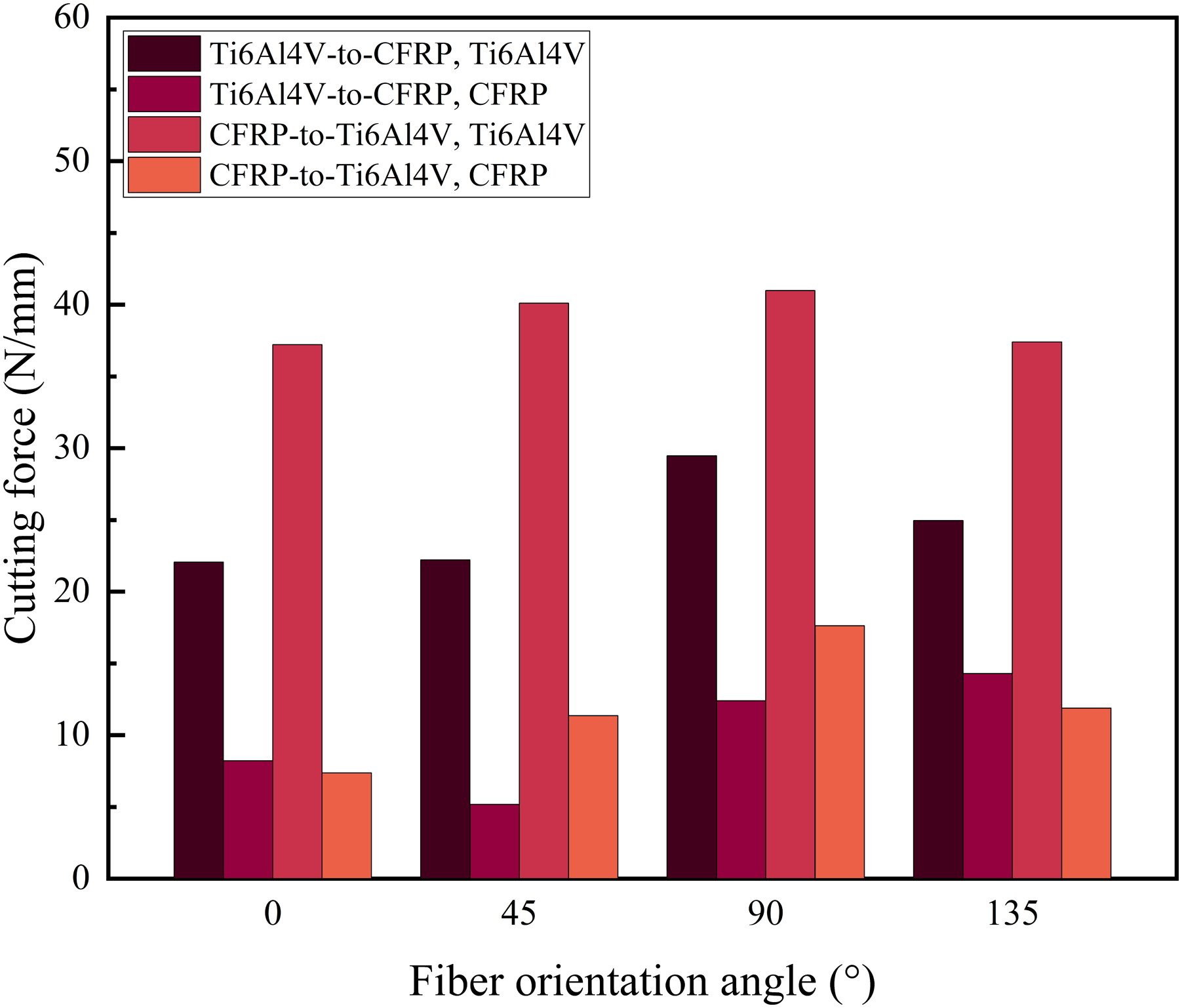
Figure 7 demonstrates the variation of two-phase cutting forces with cutting parameters in Ti6Al4V-to-CFRP sequence. In Figure 7(a), the effect of the depth of cut on cutting forces is depicted. It is evident that the cutting forces in two-phase increase as the depth of cut increases. However, the rate of increase in cutting force for the CFRP phase is slower compared to the Ti6Al4V phase. This trend aligns with the thrust analysis of feed rate in the stacked drilling experiments mentioned in Ref.
7
Specifically, the Ti6Al4V cutting force increases by 18.64 N, while the CFRP cutting force only increases by 4.98 N during the range of 5 µm to 20 µm. Comparison of cutting at different cutting parameters (a) Cutting depth (b) Rake angle (c) Edge radius.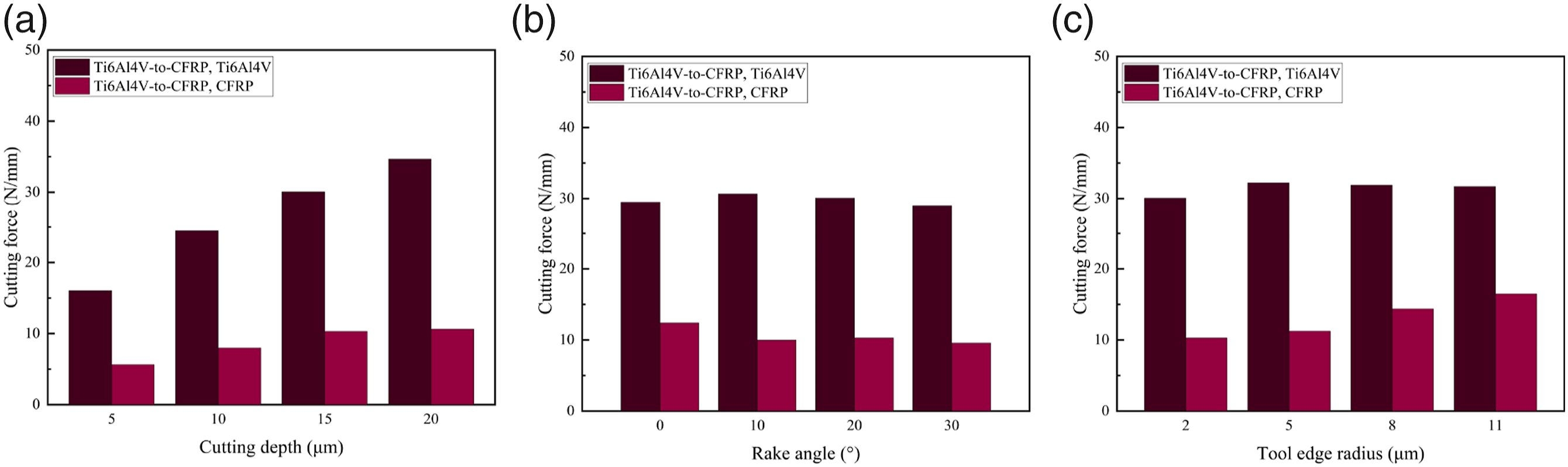
The effect of tool rake angle is shown in Figure 7 (b). It is observed that the effect of tool rake angle is not significant in this case. In Ref, 38 it was found that increasing the tool rake angle also increases the chip inclination angle upon exit. Within a certain range, a larger rake angle tool results in a sharper cutting edge, reducing the cutting force. Consequently, the cutting force on the CFRP phase is increased while that on the Ti6Al4V phase is decreased when the rake angle changes from 0° to 10°. However, the influence of the rake angle diminishes as it continues to increase. The effect of tool edge radius on the cutting force is illustrated in Figure 7(c). It is evident that an increase in the edge radius has a more pronounced effect on the cutting force of the CFRP phase. This can be attributed to the fact that a larger radius on the cutting edge enhances the occurrence of bending fracture mode in the fibers, leading to an overall rise in the cutting force. 39 Conversely, the cutting force of the Ti6Al4V does not exhibit a significant increase. The difference can be attributed to the lower load-bearing capacity of CFRP and the tilting deformation of the Ti6Al4V phase.
Fiber failure analysis
Fiber failure under CFRP-to-Ti6Al4V cutting sequence
Figure 8 illustrates the cutting process of CFRP/Ti6Al4V stacks under CFRP-to-Ti6Al4V cutting sequence. Here, in conjunction with related studies,22,27,30,40 we analyze the failure of the fiber based on stress state. As can be seen from Figure 8, Ti6Al4V produces continuous chips due to its elasto-plastic properties while CFRP chips are discontinuous and some of them are even pressed into powder due to the material brittleness. At four fiber angles, it can be observed that the stress propagates along the axial and transverse directions of fiber. Cutting process of CFRP/Ti6Al4V stacks under CFRP-to-Ti6Al4V cutting sequence (a) 0° (b) 45° (c) 90° (d) 135°.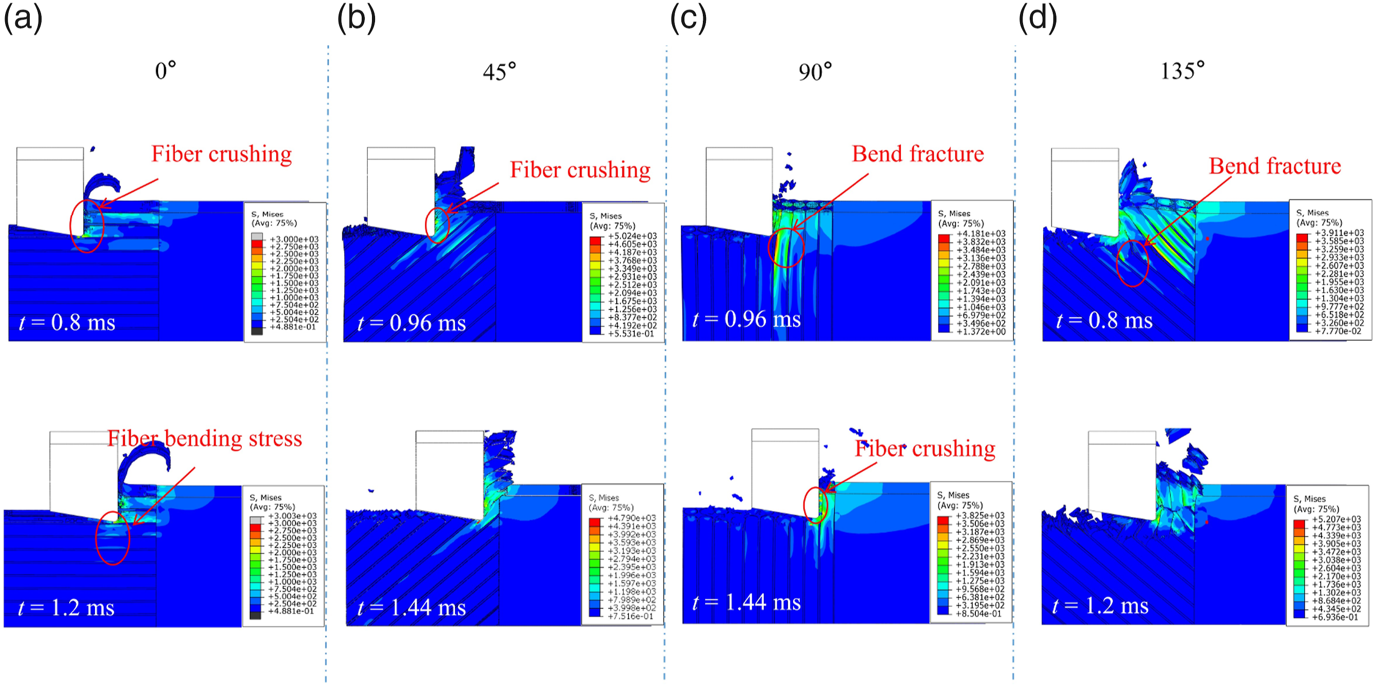
In the case of CFRP with fiber angle of 0°, the tool first contacts with the CFRP material. Due to the perpendicular rake angle of the tool to the fiber direction, the fibers experience significant axial compression failure. The damage and stress in the CFRP predominantly concentrate around the two horizontal layers of fibers that are in direct contact with the tool. For fibers under the tool, there are only slight bending stresses in the fibers and a relatively smooth machined surface is obtained. As the cutting process reaches the interface layer, a large number of fibers experience compression failure, leading to the deletion of elements. For the 45° fiber case, during the cutting process, the fiber undergoes shear fracture near the tool edge radius where the pressure is applied by the tool. And after the fiber fracture, the matrix fails in the direction of the fiber under the action of shear. This leads to the formation of blocky chips, separating from the direction of the workpiece. For the 90° fiber case, the stresses are significantly concentrated in the cutting area in front of the tool and are transmitted to the fiber ends. As the rake face of the tool contacts the CFRP, the fibers fail under radial compression. At the same time, bending fracture occurs in the fibers below the tool and some chips are retained in the cutting plane. For the 135° fiber case, the stress is concentrated above the fiber being cut by the tool. This shows a larger stress concentration area compared to other angles. This causes the fibers to exhibit a tendency to lift up. As a result, under the pressure exerted by the tool, the fibers will experience bending fracture below the cutting plane. However, the fractured fibers are not promptly removed and instead, they get pushed by the tool, resulting in cutting the rear fibers. This phenomenon leads to a reduction in the actual cutting rake angle, causing more severe fiber bending. Consequently, the machined surface becomes significantly rougher compared to other angles.
Fiber failure under Ti6Al4V-to-CFRP cutting sequence
As displayed in Figure 9, the cutting process of CFRP/Ti6Al4V stacks under the Ti6Al4V-to-CFRP cutting sequence involves the presence of Ti6Al4V chips that replace the tool for cutting the CFRP material. The edge shape of Ti6Al4V chips is approaching that of a tool with a negative rake angle. It can be seen that due to the incapacity of CFRP to provide sufficient support for Ti6Al4V, the tilting deformation and chips of the Ti6Al4V workpiece during the cutting process severely affects the CFRP phase. When the fiber angle is 0°, some fibers fail in axial compression, while others slide along the upper face of the chip and experience bending fractures under negative rake angle. For fiber angles of 45° and 90°, the tool pushes the Ti6Al4V chip to cut through the CFRP. As a result, the fiber in the CFRP undergoes extrusion and bending failure. Subsequently, the fiber chip separates from the CFRP, and both chips slide out from the workpiece surface. Then the tool starts cutting the CFRP phase directly. For the 135° fiber case, the fibers exhibit more obvious bending fractures under the tool. Additionally, some of the fibers are lifted up, preventing the Ti6Al4V chips from sliding out of the workpiece, which contributes to a higher surface roughness on the CFRP material. Cutting process of CFRP/Ti6Al4V stacks under Ti6Al4V-to-CFRP cutting sequence (a) 0° (b) 45° (c) 90° (d) 135°.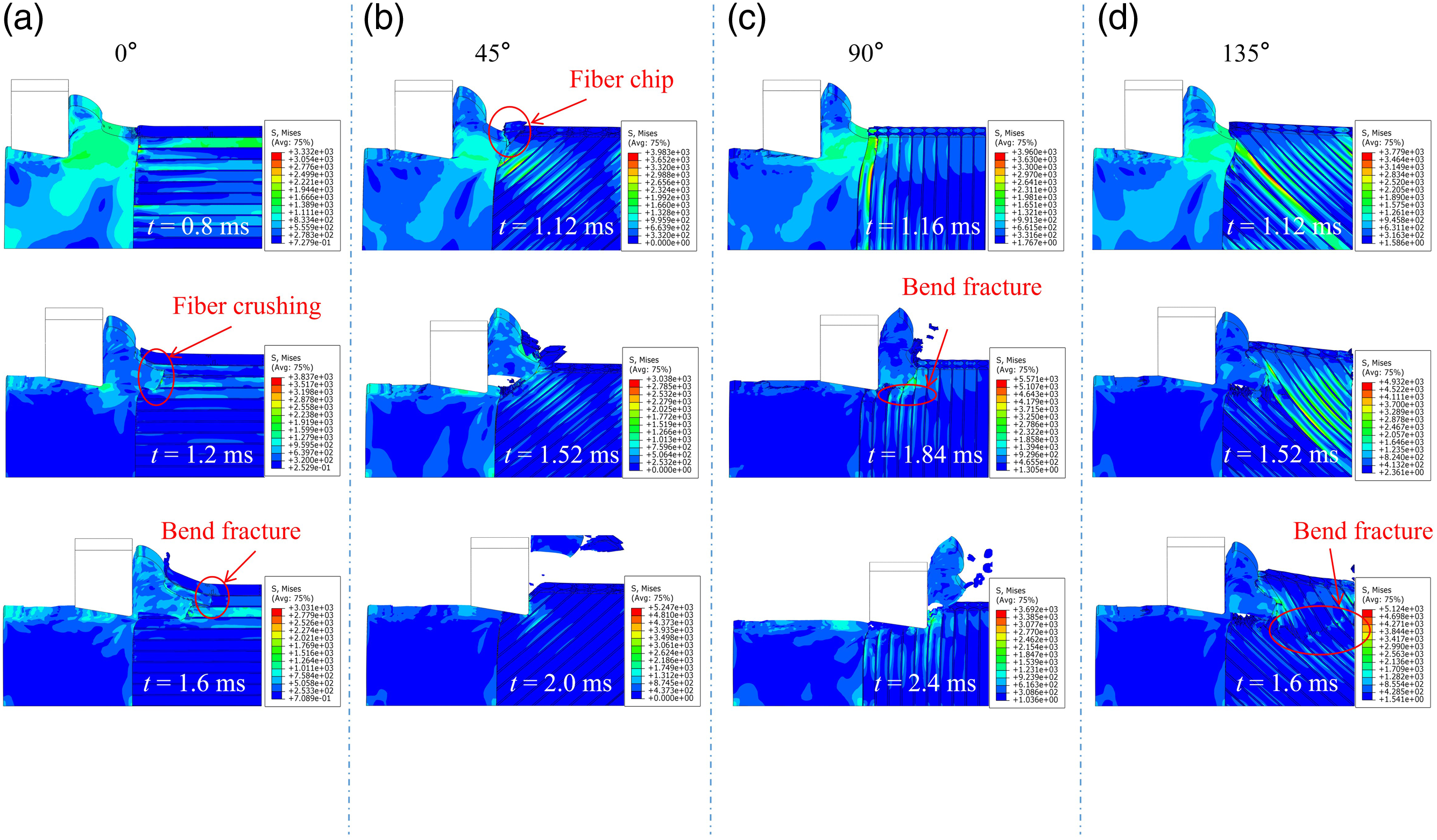
Matrix and interface damage analysis
Analysis of matrix damage
Figure 10(a)-(d) show the matrix ductile damage in the CFRP-to-Ti6Al4V cutting sequence, while Figure 10(e)-(h) show the matrix ductile damage in the Ti6Al4V-to-CFRP cutting sequence. In the CFRP-to-Ti6Al4V cutting sequence, the presence of Ti6Al4V plays a significant role in supporting the generation of matrix damage and inhibits the bending deformation of CFRP. For the four angles, the depth of matrix damage decreases as it approaches Ti6Al4V. This indicates that the presence of Ti6Al4V plays an important supporting role for CFRP and reduces the fiber bending. Once the tool completes cutting in the CFRP, further feeding of the tool does not have significant effect on the matrix damage. In the Ti6Al4V-to-CFRP cutting sequence, the deformation of the Ti6Al4V phase plays an important effect on the extrusion of CFRP to produce matrix damage at the interface. Additionally, the negative rake angle of the chips also contributes to the increased matrix damage. In Figure 10(e)-(h), severe ductile damage appears on the left side of the matrix at each angle. To measure the maximum matrix damage depth under two conditions, the area where the ductile damage reaches 0.99 is taken as the matrix damage failure area. The maximum matrix damage depth occurs at the interface of 0°-90°. For a fiber angle of 135°, the fibers produce large bending deformations, and the depth of matrix damage along the fiber direction exceeds that at the interface. Matrix damage of CFRP with four different fiber angles. CFRP-to-Ti6Al4V: (a) 0° (b) 45° (c) 90° (d) 135°; Ti6Al4V-to-CFRP: (e) 0° (f) 45° (g) 90° (h) 135°.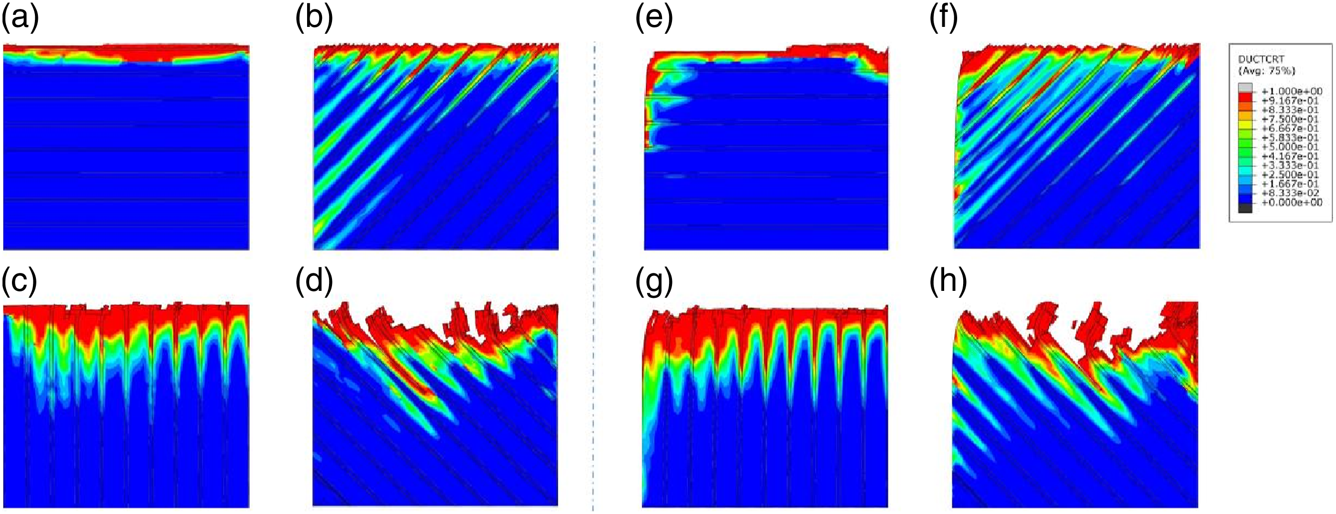
Figure 11 shows the maximum matrix damage depth of CFRP with four different fiber angles under two cutting sequences. It can be seen that, as the fiber angle increases, the matrix damage in CFRP also increases, with the maximum damage occurring at fiber angle of 135°. Besides, in the CFRP-to-Ti6Al4V cutting sequence, the depth of matrix damage is consistently lower for different fiber angle cases compared to that in Ti6Al4V-to-CFRP cutting sequence. In Ref.
25
the 90° fiber angle matrix damage reaches its maximum value in both sequences, the difference is due to the difference between the material properties, and in the cutting experimental of CFRP in Ref,
41
the matrix damage produces a similar trend. Maximum matrix damage depth of CFRP with four different fiber angles.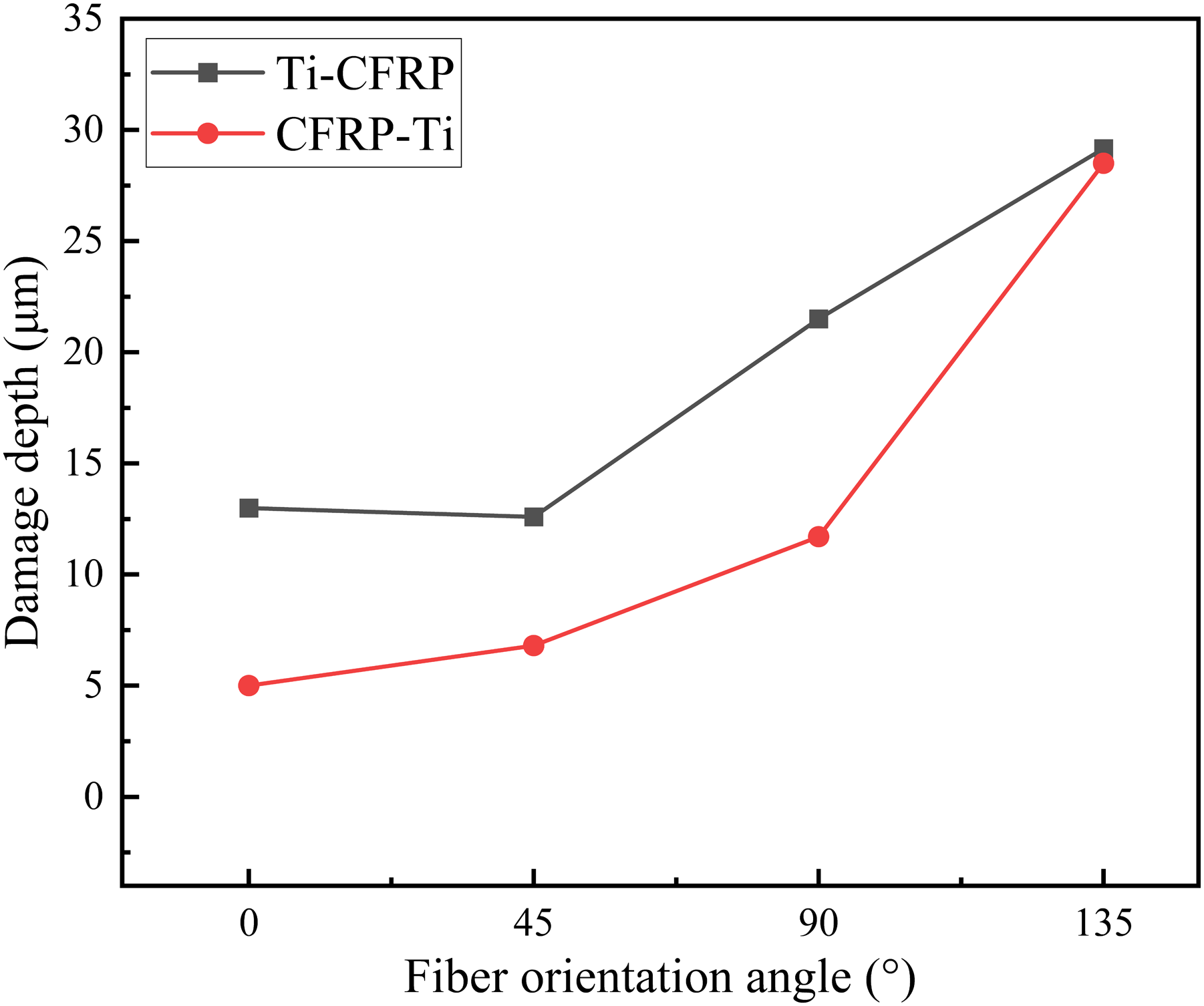
Analysis of interface damage
Interface delamination is identified as the primary failure mechanism in the machining of CFRP/Ti6Al4V stacks. The interface damage depth is the distance between the ideal cutting surface and the deepest failure zone. Figure 12 describes the interface failure in CFRP/Ti6Al4V stacks with fiber angles of 90° under two different cutting sequences. In the Ti6Al4V-to-CFRP cutting sequence, the interface damage shows larger values and develops more quickly. It can also be found that the size of the interface damage is greater than the matrix damage, with damage depths of 21.5 μm and 43.5 μm, respectively. Interface damage of CFRP/Ti6Al4V stacks with two fiber angles under two cutting sequences (a) 90°, CFRP-to-Ti6Al4V (b) 90°, Ti6Al4V-to-CFRP.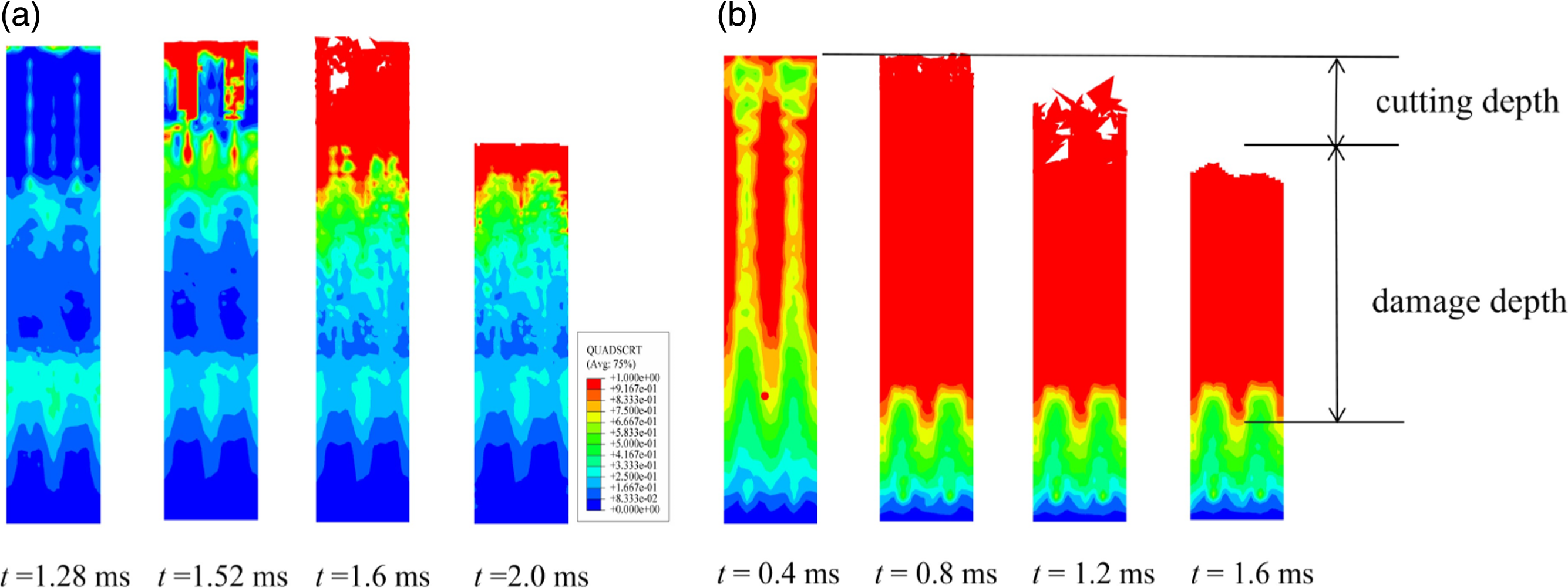
Analysis of the influence of cutting parameters on interface and matrix damage
In this section, the influence of three cutting parameters, namely cutting depth, edge radius, and rake angle, on the interface damage and matrix damage is examined for CFRP/Ti6Al4V stacks with a 90° fiber angle in the Ti6Al4V-to-CFRP cutting sequence.
In Figure 13(a), the effect of cutting depth is demonstrated with the tool rake angle set as 20° and edge radius set as 2 μm. The damage variation is analyzed at cutting depths ranging from 5-20 μm. It can be observed that both matrix damage and interfacial damage increase with the depth of cutting. The increase in cutting depth leads to a larger contact area between the tool and the stacks material. This results in greater deformation of Ti6Al4V with larger chip generation, ultimately leading to the increased depth of damage. A comparable pattern was observed in a simulation study on the influence of the depth of cut on subsurface and delamination damage in 0° stacks, as reported in Ref.
26
As the depth of cut increased from 5 to 20 μm, the extent of matrix damage increased by 11.7 μm, while interfacial damage increased by 6 μm. In Figure 13(b), the effect of tool rake angle is illustrated with the edge radius set as 2 μm and cutting depth of 15 μm. It is observed that the depth of damage decreases with increasing tool rake angle. The maximum values of 21.5 μm and 45.3 μm are obtained for matrix damage and interfacial damage at a tool rake angle of 0°. The decrease in tool rake angle leads to an increase in the deformation of the Ti6Al4V material. The increased rake angle of the tool facilitates easier chip sliding along the rake face and reduces chip extrusion on the rake face. In Figure 13(c), the effect of edge radius is depicted with the tool rake angle set as 20° and cutting depth of 15 μm. As the edge radius increases, both the depth of interfacial damage and matrix damage in the CFRP/Ti6Al4V stacks increase. During the increase in tool edge radius from 2 to 11 μm, matrix damage increased by 8.4 μm and interfacial damage increased by 10.5 μm. The decrease in effective rake angle resulting from an increase in edge radius, coupled with the decrease in rake angle, leads to an increase in interfacial and matrix damage. These results are consistent with the previous analysis regarding the effects of rake angle. Interface damage and matrix damage affected by different cutting parameters (a) Cutting depth (b) Rake angle (c) Edge radius.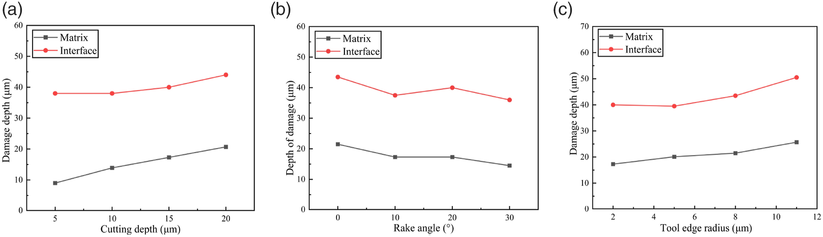
Conclusions
In this study, a microscopic FE model of CFRP/Ti6Al4V stacks is employed to simulate the cutting process under two different cutting sequences. The cutting mechanisms are analyzed by studying the cutting forces, fiber failure, matrix failure, and interface delamination. The main conclusions drawn from this work are as follows: • The variation of cutting forces becomes increasingly complex in the Ti6Al4V-to-CFRP sequence. The interaction between Ti6Al4V and CFRP involves extrusion, cutting of Ti6Al4V chips against the CFRP, and the subsequent separation of chips from the workpiece. These processes significantly influence the cutting forces. In contrast, the cutting force changes more smoothly in the CFRP-to-Ti6Al4V sequence. • The fiber angle in the Ti6Al4V-to-CFRP sequence influences not only the cutting force of CFRP, but also influences the cutting force of Ti6Al4V. Additionally, the fiber angle also affects the cutting time of Ti6Al4V chips on CFRP, and when the chips slip out, it results in a reduction of the cutting force. • In the Ti6Al4V-to-CFRP sequence, the cutting forces of Ti6Al4V phases are lower compared to that in the opposite cutting sequence. Furthermore, an increase in the depth of cut significantly amplifies the cutting forces of both phases. Conversely, decreasing the tool rake angle can moderately reduce the cutting forces. Moreover, the edge radius of the tool has a more substantial impact on enhancing the cutting forces of the CFRP phase compared to the Ti6Al4V phase. • Fiber angle plays a critical role in the extent of matrix damage, with an increase in fiber angle directly correlating to an increase in matrix damage. Due to the deformation of Ti6Al4V phase in the cutting process and chip cutting CFRP, more severe matrix damage is produced in the Ti6Al4V-to-CFRP cutting sequence. In the cutting sequence of Ti6Al4V-to-CFRP, reducing the cutting depth, decreasing the tool edge radius, and increasing the tool rake angle can effectively mitigate both matrix damage and interface damage. • The obtained results offer valuable insights into the cutting behavior of CFRP/Ti6Al4V stacks, aiding in the optimization of the machining process for this composite system. Besides, it should be pointed out that thermoplastic materials are difficult to remove during the cutting process due to their high plasticity. This simulation method can also be applied to the study of cutting mechanisms in thermoplastic composite materials and metal laminates.
Footnotes
Declaration of conflicting interests
The author(s) declared no potential conflicts of interest with respect to the research, authorship, and/or publication of this article.
Funding
The author(s) disclosed receipt of the following financial support for the research, authorship, and/or publication of this article: This work was supported by the Natural Science Foundation of Jiangsu Province (BK20231319) and State Key Laboratory of Mechanics and Control for Aerospace Structures (Nanjing University of Aeronautics and astronautics) (MCAS-E-0124G03).