
Abstract
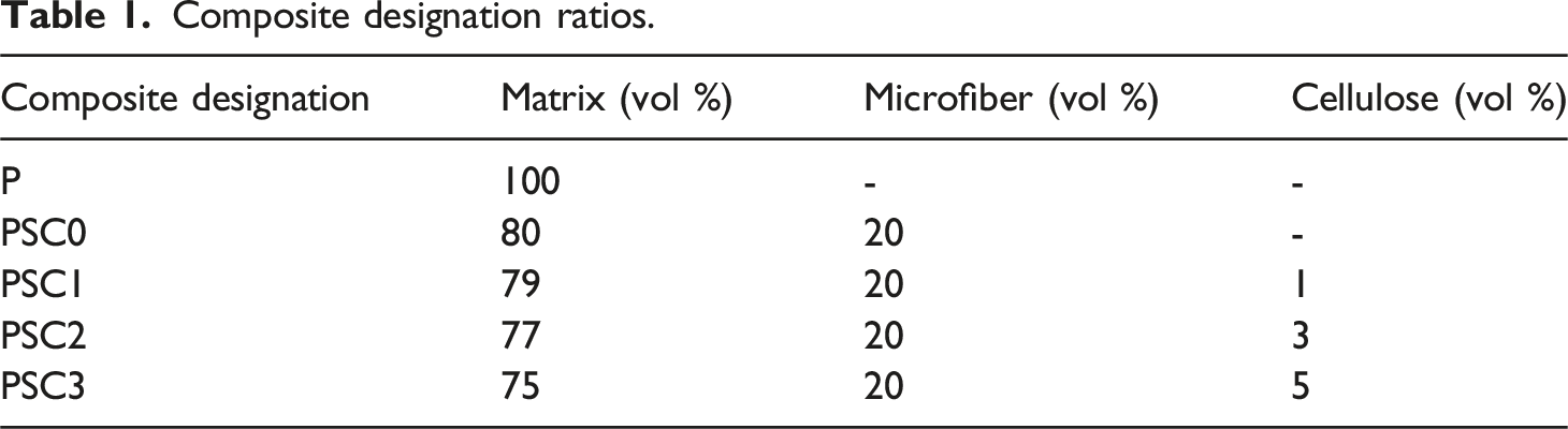
This study addresses the need for sustainable, high-performance biomaterials for bone-regeneration applications by investigating additive-manufactured PLA scaffolds reinforced with 20 vol % silane-treated sorghum husk microfiber and varying amounts of silane-treated bagasse pith cellulose. Such agro-waste–derived fillers offer renewable, low-cost alternatives to conventional synthetic reinforcements while improving scaffold performance. Mechanical testing showed significant improvements over neat PLA, with PSC2 (3 vol% silane-treated cellulose) achieving the best overall performance: tensile strength of 135.3 MPa, flexural strength of 150.7 MPa, impact energy of 3.586 J, and hardness of 94.6 Shore D, attributed to enhanced interfacial bonding and uniform filler dispersion. Swelling and degradation tests confirmed PSC2 as the most hydrolytically stable composition, while PSC3 (5 vol % cellulose) exhibited superior fire resistance due to dense char formation. SEM analysis supported these findings, revealing fiber pull-out in PSC0, uniform dispersion in PSC2, and filler agglomeration in PSC3. Overall, the study demonstrates that controlled hybrid reinforcement using silane-treated agro-waste fibers and fillers can sustainably enhance mechanical, thermal, and hydrolytic properties, providing a balanced and eco-friendly solution for bone scaffold applications.
Introduction
In the earliest attempts to restore damaged bone, clinicians relied on rigid metallic implants, allografts, and ceramic based grafting materials to support defect repair. Although these systems provided essential temporary support, they frequently exhibited biological incompatibility, improper stiffness compared with natural bone, limited ability to degrade in a controlled manner. Moreover, their fabrication methods did not allow precise control over porosity or internal architecture, which limited cell infiltration, nutrient flow, and progressive tissue regeneration. Therefore, the need for scaffolds with improved biocompatibility, regulated degradation, and controlled structural design became increasingly apparent. 1 Consequently, additive manufacturing provided a promising route for producing scaffolds with tailored pore networks and optimized internal geometry suitable for osseous repair. In addition, polylactic acid emerged as a widely preferred matrix due to its biodegradability, favourable biological response, and thermal stability during extrusion based fabrication. Yet, polylactic acid alone lacks the toughness, stiffness, and surface activity needed for advanced bone regeneration applications. For this reason, natural fiber reinforcement gained attention as a method to improve the properties of polylactic acid scaffolds. 2 Moreover, natural reinforcements are biodegradable, cost-effective, and renewable, making them ideal for sustainable bone-regeneration scaffolds. 3 Their mechanical and functional properties depend on factors such as fiber source, chemical composition, aspect ratio, and interfacial bonding with the matrix. Therefore, this research utilize sorghum husk microfiber obtained from the plant commonly known as sorghum, which also belongs to the Poaceae botanical family. In fact, sorghum husk contains approximately thirty to forty percent cellulose, which provides structural rigidity, moderate crystallinity, and inherent fibrous strength. Additionally, its microfiber form offers a large surface area for bonding, supports improved stress distribution, and enriches the composite with natural surface morphology that benefits biological interaction. Thus, scholars showed more interest about employing the natural fiber in the composite. For example, Vinod et al. 4 fabricated a three dimensional printed natural fiber reinforced PLA composite and reported a tensile strength of 74.82 MPa. Similarly, Saha et al. 5 investigated a three dimensional printed banana fiber reinforced PLA composite and observed a tensile strength of 62.45 ± 2.10 MPa, flexural strength of 79.78 ± 3.51 MPa, and compressive strength of 60.73 ± 2.10 MPa. Likewise, Compton et al. 6 examined a SiC microfiber reinforced polymer composite and noted an improvement in flexural strength, reaching 97.8 ± 2.10 MPa.
Even though, the addition of fiber shows numerous advantages, certain limitations were produced such as void formation and low compatibility between reinforcement and matrix. To mitigate such defects, filler incorporation is the most effective way which will improve the strength properties. In this work, bagasse pith extracted cellulose particles is employed which provides crystallinity, tensile strength, and enhanced thermal stability. 7 Moreover, filler integration enhances the microstructural stability of the scaffold and promotes surface textures favourable for cell adhesion. Numerous works were incorporated cellulose as filler reinforcement and evaluate its strength properties. Typically, Divakaran et al. 8 evaluated a composite reinforced with cellulose particles extracted from Tamarindusindica seeds and recorded a tensile strength of 36.11 ± 2.90 MPa. In similar work, Senthamaraikannan et al. 9 analyzed a composite incorporating cellulose particles derived from Terminaliacatappa leaves and reported a tensile strength of 23.05 MPa. Likewise, Alshahrani et al. 10 examined a composite reinforced with Sunn hemp fiber and cellulose particles obtained from waste Pisumsativum sheaths and documented a tensile strength of 141.0 MPa, a flexural strength of 163.0 MPa, and a hardness of 84.0 Shore D.
However, natural microfibers and filler particles are inherently hydrophilic, which leads to poor bonding with the hydrophobic polylactic acid. 11 Treating these reinforcements with silane modifies their surface chemistry, enhancing adhesion, dispersion, and stress transfer, and thereby significantly improving the overall performance of the composite.12,13 Hence, silane treatment becomes essential to overcome the interfacial incompatibility between the reinforcement phase and the polymer matrix.14,15 In addition, silane coupling agents form covalent linkages with the hydroxyl groups on sorghum husk microfiber and bagasse pith cellulose, while simultaneously anchoring to the polymer matrix, resulting in improved adhesion and reduced moisture absorption. Furthermore, silane treatment is applied to both the natural fibers and the filler particles in this research to minimize voids, enhance dispersion, and ensure cohesive matrix reinforcement integration. Further, the silane treated reinforcement employed in some researches which are given below. Typically, Li et al. 16 investigated a composite reinforced with silane modified sisal fiber and cellulose particles and recorded improvements of 20.71% in tensile strength, 15.74% in hardness, and 43.95% in tear strength. In related work, Kandavalli et al. 17 analyzed a composite containing silane treated cotton microfiber and biosilica particles and reported a tensile strength of 120.0 MPa along with a specific wear rate of 0.22 mm3/Nm. Correspondingly, Liang et al. 18 demonstrated a composite reinforced with silane modified cellulose particles and documented tensile strength values in the range of 37.9-47.3 MPa.
In conclusion, three dimensional printed composites reinforced with natural microfibers and functional filler particles offer considerable potential for producing biomaterials applicable to bone regeneration. The present work aims to fabricate a composite incorporating sorghum husk microfiber and bagasse pith derived cellulose particles subjected to silane modification and to examine its mechanical, thermal, and physical characteristics. While both reinforcements have been employed separately in earlier investigations, their combined incorporation with silane mediated interfacial enhancement has not been documented in the existing literature, thereby revealing a clear research gap. The current work addresses this gap through systematic fabrication and characterization, thereby establishing the novelty of the approach. Furthermore, the resulting composite is suitable for manufacturing bone regeneration scaffolds, orthopaedic implant spacers, biodegradable fixation plates, and biodegradable product casings.
Experimental workflow
Raw materials
PLA –approximately has 60°C of glass transition temperature because it becomes soft and rubbery at this temperature and it was secured from Natu Tec India, Chennai. Sorghum husk – secured from Sri Sai Traders, Chennai, India. Bagasse pith – secured from Green Creeper Enterprises, Chennai, India. 3APTMS–it has a density of 1.026 g/ml at 25°C which was secured from ESS Emm Chemicals, Chennai, India. Ethanol –has a specific boiling point at 77.37°C and it was secured from Laywell Composites, Chennai, India. Filter paper–secured from Triveni Chemicals, Chennai, India.
Detachments of microfibers from Sorghum Husk
Cleanse the sorghum husk in running water to remove dust. Shred the husks to 3 cm pieces with the help of bench cutter so treatments penetrate evenly. Again cleanse the shredded husk thoroughly with tap water followed by distilled water until wash water runs clear to remove soluble impurities and dust. Oven dry the washed husk at 60°C for 6 h to remove moisture and standardize starting materials. Figure 1 presents microfiber separation form sorghum husk. Prepare 5 wt % of NaOH solution, soak the husk, stir for 2 h this softens the bonding matrix and loosen microfibers. Filter and wash the solid repeatedly with distilled water, if residual alkalinity was detached neutralize briefly with dilute acetic acid. Bleaching process were undergone with 3% hydrogen peroxide for 30 min this brightens fibers and cleans surface impurities. Resuspend the treated husk in water to break fiber bundles into microfibers. At the end dry the isolated microfibers in oven at 65°C.
19
Microfibers separation process.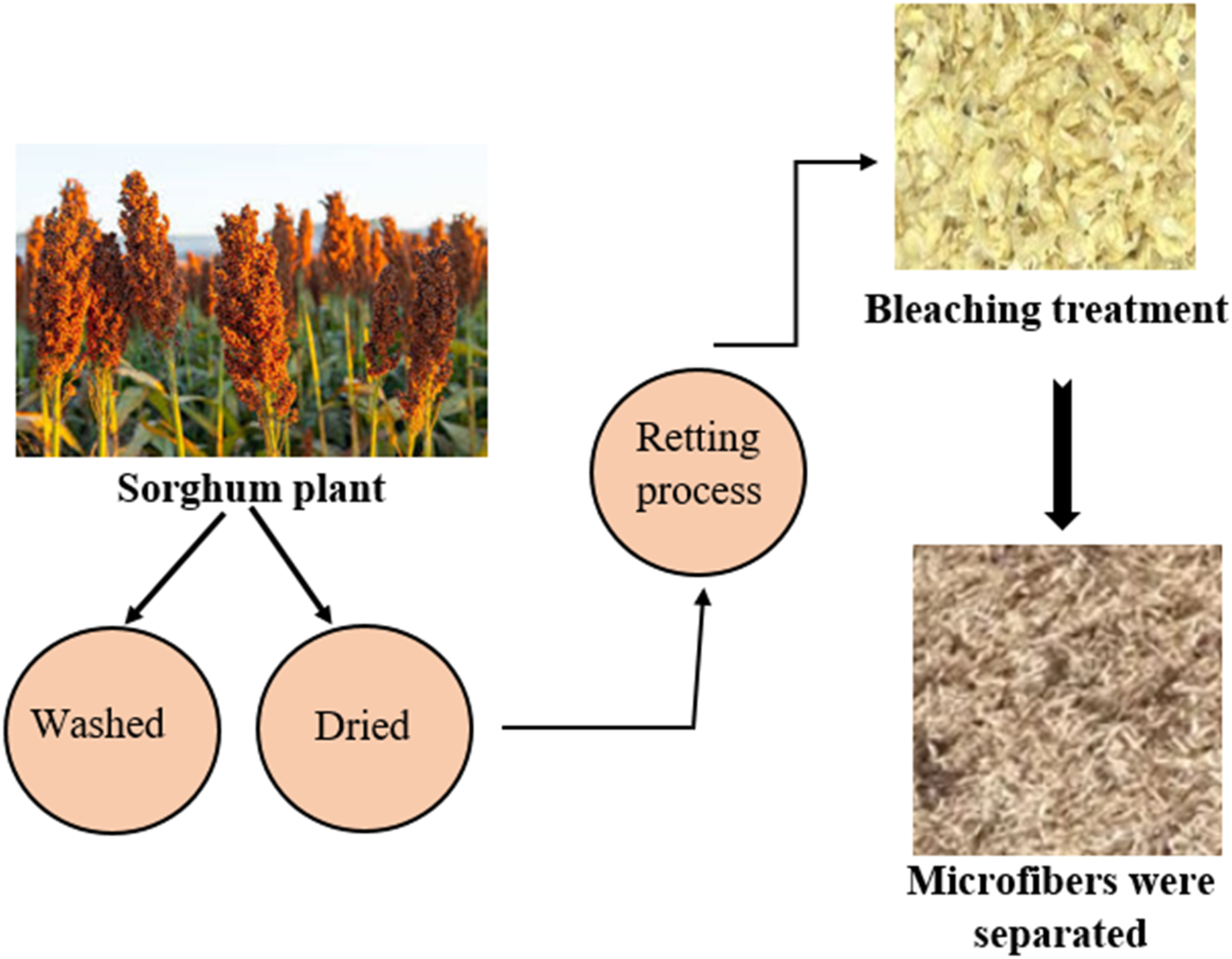
Cellulose preparation from bagasse pith
Oven dry the bagasse pith at 46°C, milled to < 1 mm particle size to obtain uniform particles. 100 g of milled bagasse pith was washed with tap water, then with distilled water to remove sugars and dirt. Now prepare 10 vol % of NaOH solution, add 100 g of pith heat to 85°C this solubilizes lignin and part of hemicellulose. Cool, filter and wash the solid repeatedly with hot distilled water, if solids are strongly alkaline add dilute acetic acid slowly with stirring. Similarly, prepare bleaching mixture with 3% hydrogen peroxide under alkaline condition at 65°C for 1 h.
20
After the bleaching process gets over, filter, wash and collect the bleached cellulose pulp keep it in a moisture free container. The cellulose particles had an average particle size of 45 ± 10 µm and an average aspect ratio of 15 ± 3. Figure 2 visualizes cellulose recovery from bagasse pith. Cellulose extraction method.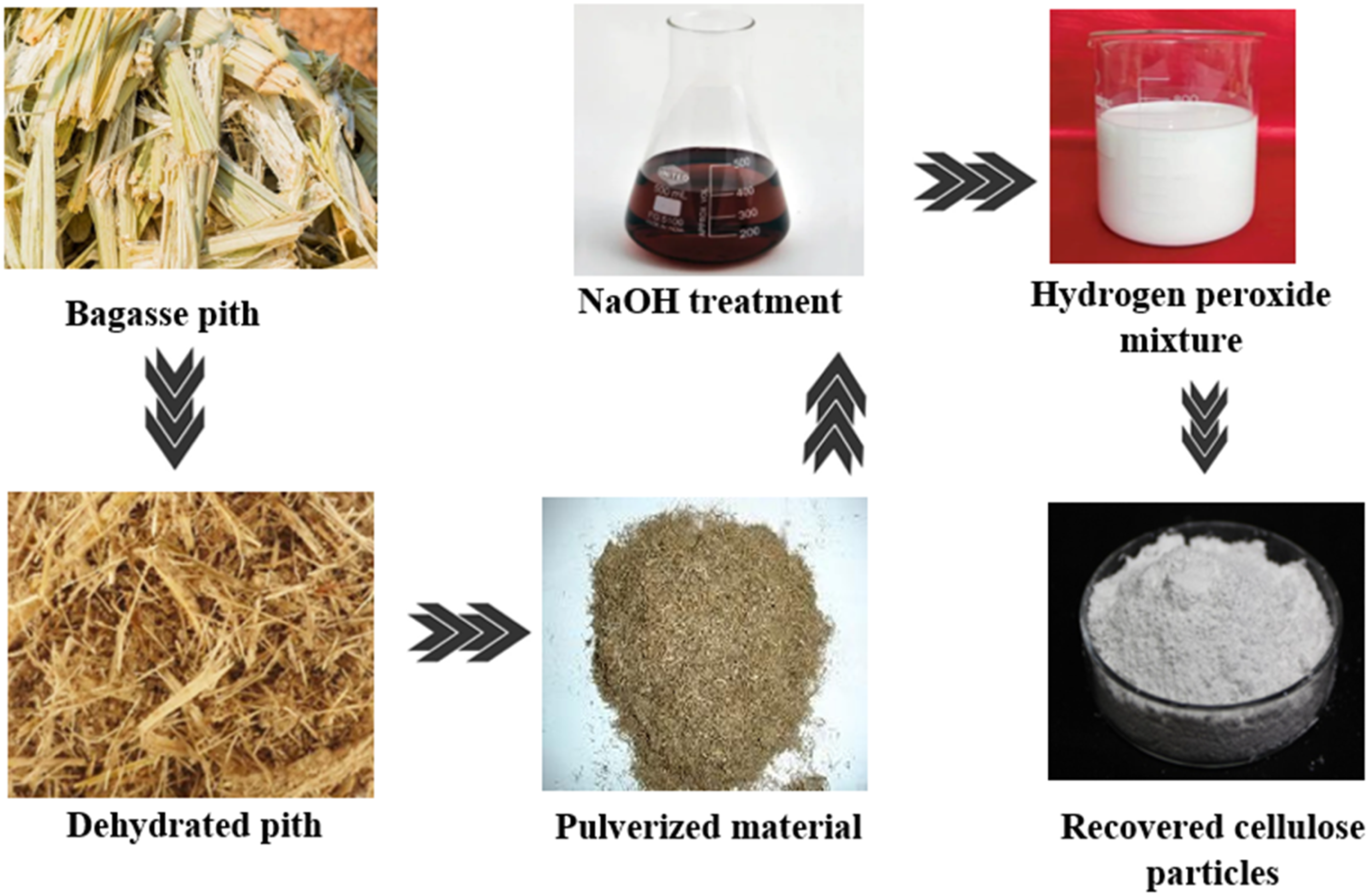
The XRD pattern of the cellulose particles, shown in Figure 3, exhibits distinct diffraction peaks at 2θ ≈ 15° (110), 22° (200), and 35° (004), which are characteristic of the cellulose I crystalline structure. The strong and sharp 200 peak indicates that the cellulose has a dominant crystalline phase, while the moderate broadening of the (110) and (004) peaks suggests the presence of partial amorphous regions. These observations are consistent with previous studies, where natural cellulose extracted from agro-waste sources retained the cellulose Iβ polymorph with similar peak positions and crystallinity profiles.21,22 XRD spectrum of isolated cellulose particles.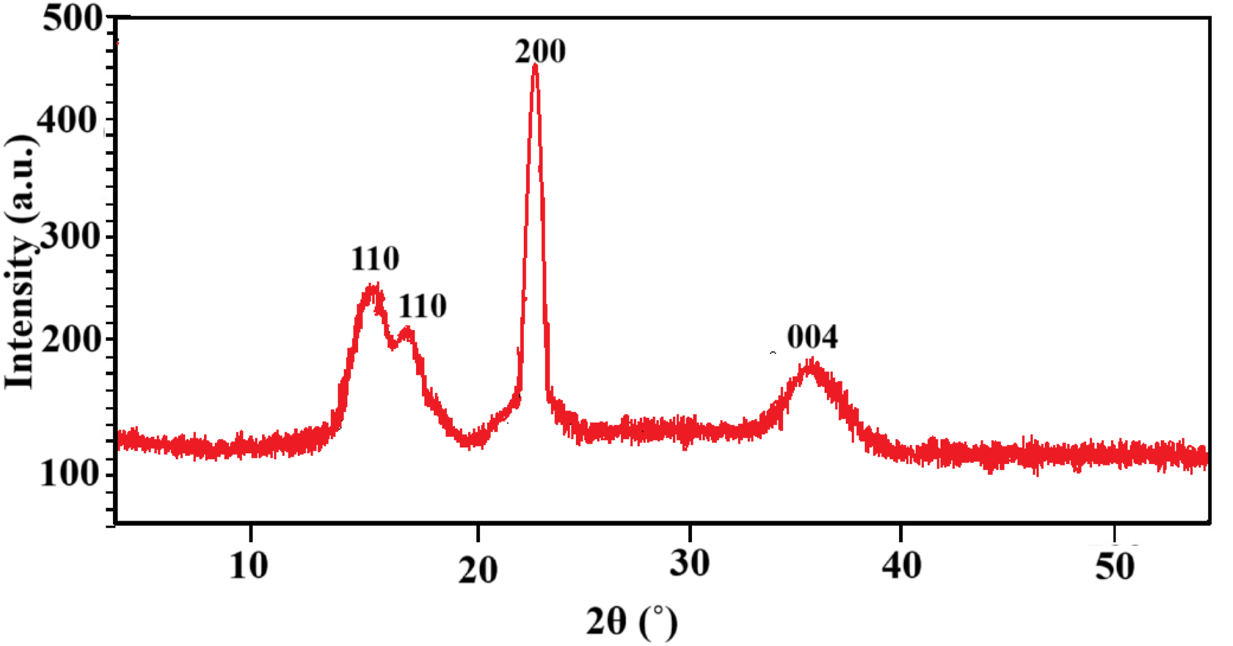
Silane based interfacial enhancement
The chemical formula of the silane coupling agent 3-APTMS is C6H17NO3Si, and its structural formula is H2N–(CH2)3–Si(OCH3)3. During the hydrolysis step, the alkoxy silane group [–Si(OCH3)3] is converted into silanol (–SiOH). These silanol groups can then condense with hydroxyl groups (–OH) present on the surfaces of the reinforcing materials. The remaining amine groups subsequently bond with the matrix.
To prepare the silane treatment medium, 2 wt % of 3-aminopropyltrimethoxysilane (3-APTMS) was diluted in a 95% aqueous ethanol solution (95:5 v/v), and the pH of the solution was adjusted to approximately 4.5 using acetic acid to facilitate silane hydrolysis. The solution was continuously stirred for 120 min at room temperature to promote complete hydrolysis. The reinforcing materials (fiber and filler) were then separately immersed in the hydrolysed silane solution for 24 h to enable effective condensation between silanol groups and the surface hydroxyl groups of the materials.
23
After treatment, the functionalized reinforcements were removed and thoroughly rinsed with deionized water to eliminate unreacted silane residues. Finally, the treated materials were oven-dried at 120°C for 20 min to remove residual moisture. The overall silane modification process is schematically illustrated in Figure 4. The entire process of silane treatment.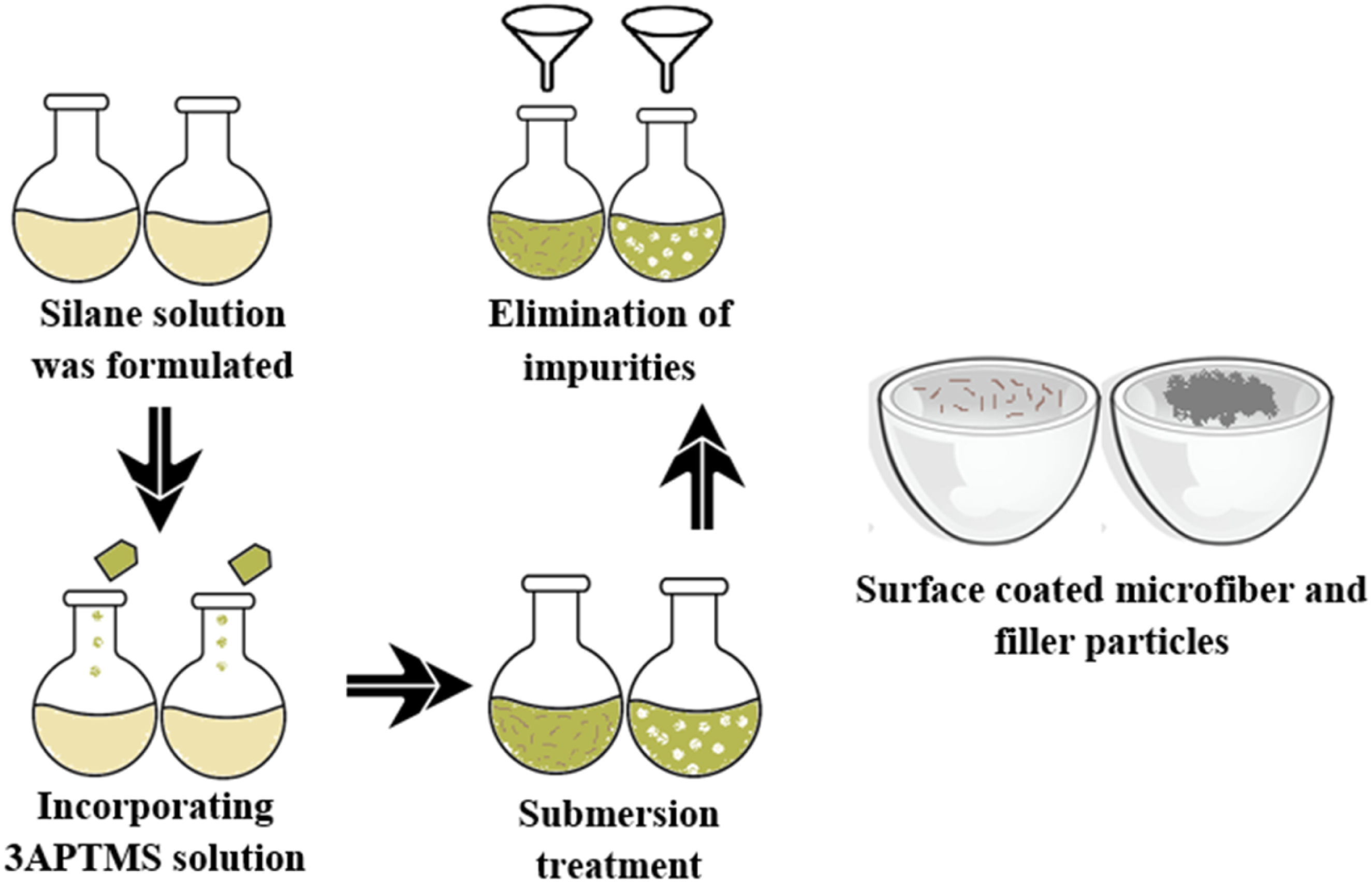
Preparation of filaments
Mixing and compounding
In this step, PLA pellets were mechanically blended with silane-treated reinforcements and then melt-compounded using a Twin-Screw Filament Extruder (Model: SHJ20) equipped with a 1.75 mm nozzle. This melt-compounding approach is commonly adopted as it eliminates the need for solvent-based processing.
Melt extrusion
During the filament extrusion stage, the blended material was melted and extruded to ensure uniform dispersion of the reinforcements within the PLA matrix. The extruder temperature was maintained at 300°C, and the screw speed was set to 50 r/min from the hopper to the die. A continuous filament strand of 1.75 mm diameter was produced and collected for subsequent 3D printing. The extrusion process was carried out under the following operating conditions: a collection rate of 0.5 m/min, torque of 40 Nm, and an average filament output rate of 135.6 g/h.
Cooling
After extrusion, the hot filament was passed through a water bath to enable rapid cooling, solidification, and dimensional stabilization.
Spooling
Printing process of specimens
Model designing and slicing
The specimen geometry was created using CATIA V5 design software and exported as an STL file. The STL model was then processed in the FDM Pratham 3.0 slicing software, which generated the corresponding G-code by defining parameters such as layer thickness, printing speed, infill density, and temperature settings. 25
Printing setup
To facilitate easy removal of printed samples, the build platform (printing bed) was thoroughly cleaned and coated with a release agent prior to printing. The printing parameters were then configured, including a nozzle temperature in the range of 240-280°C, an infill ratio of 100%, and retraction settings consisting of a 3 mm retraction distance and a retraction speed of 55 mm/s.
Printing process
The prepared composite filament was fed into the heated nozzle, melted, and deposited layer by layer (approximately 40 layers) based on the G-code instructions. Each deposited layer fused with the previous one, gradually forming the complete 3D specimen. Figure 5 shows schematic representation of specimen printing process. Schematic representation of specimen printing process.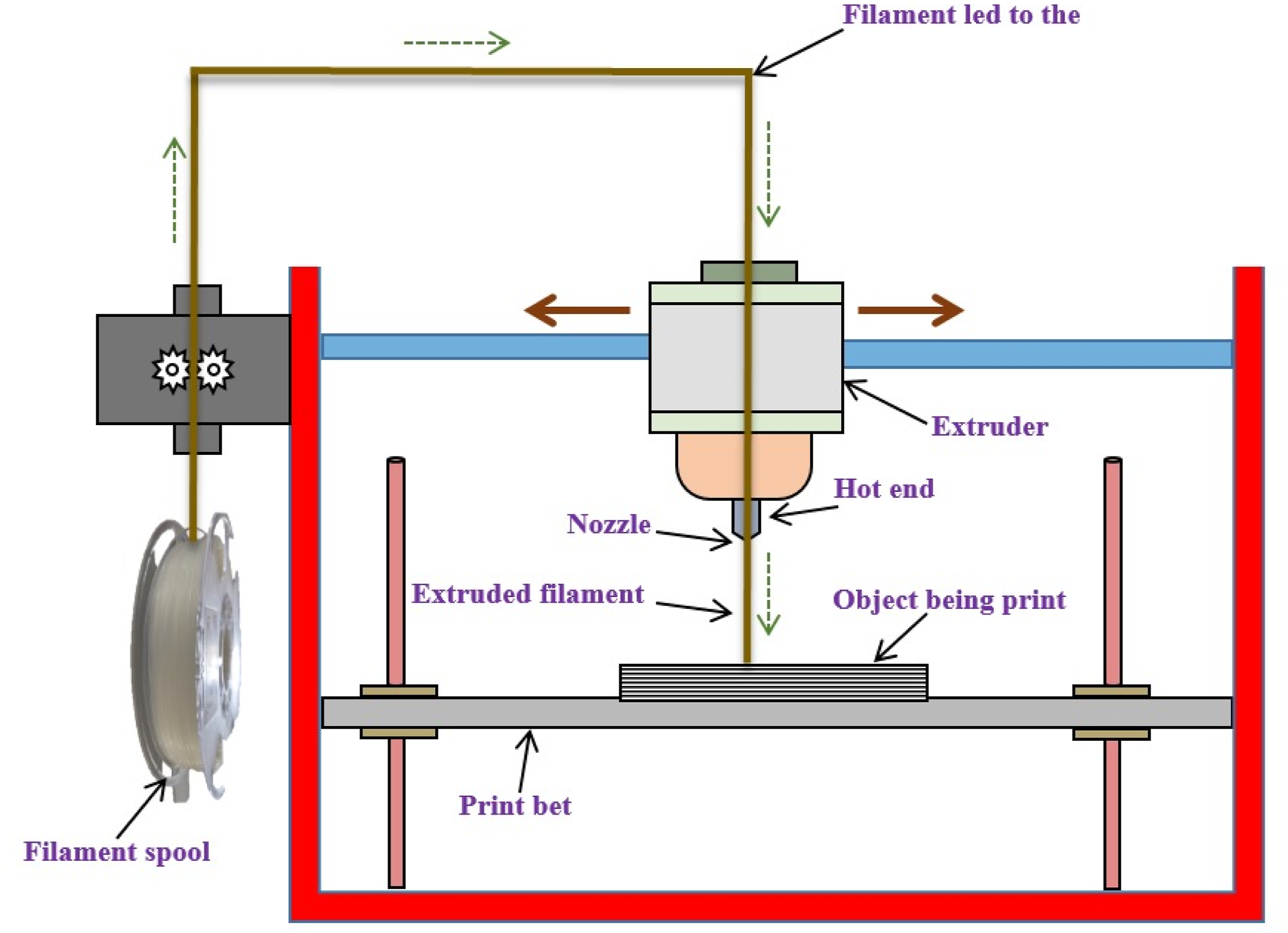
Post-printing process
Following printing, the specimen was allowed to cool gradually to ensure dimensional stability and strong interlayer bonding. Once cooled, the specimen was carefully removed from the build plate to prevent any structural damage.
Characterization analysis
Characterization of composite materials involves understanding their unique anisotropic properties through mechanical tests (tensile, flexural, impact, hardness) flammability, swelling and degradation. Each test was repeated five times to ensure repeatability, and the average of the measured values was reported as the strength of the printed specimens. The printed specimens were shown in Figure 6. Trimmed reinforced specimens.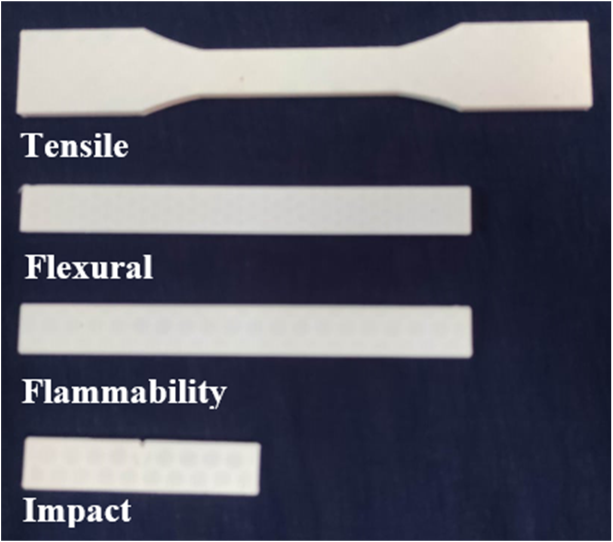
Mechanical properties
In a Universal testing machine (Instron 3369) ensuring proper alignment. Now a constant crosshead speed was applied according to ASTM D3039 until the specimen begin to deform. The test stops at specimen fracture and ultimate tensile elongation at break was calculated automatically by the machine software. Similarly, for flexural test composite specimen was dimensioned according to ASTM 790 and place on the supports of a three point bend fixture, the setup was mounted on a Universal Testing Machine (UTM), Model: Instron 3369. Now the loading nose was aligned at specimen midpoint to ensure uniform bending during the test, a constant crosshead speed was applied until the specimen experiences fracture. The machine software records load deflection data, from which flexural strength was calculated. As well as for impact test specimen was precisely positioned in the holding vice of the impact tester (Charpy Impact Testing Machine – Model: IT 30, Tinius Olsen to ensure stable alignment. The pendulum hammer was elevated to a fixed height corresponding to the required impact energy and suddenly hammer was released to strike the notched specimen causing sudden fracture under dynamic loading. The absorbed energy was automatically recorded and fractured sample was collected for visual to evaluate crack initiation based on the ASTM D256. Further, the polished composite specimen was placed on the Wilson Rockwell Hardness Tester, Model: 574 series, indenter tip was selected based on the material category and mounted securely. A preliminary minor load was applied based on the ASTM D2240 to set the zero reference point for indentation and major load was then applied automatically finally the indentation depth was recorded by the system.
Flammability test
For flammability analysis specimen was conditioned for 24 h and then mounted vertically inside the UL-94 Vertical Flame Chamber (Model: Instron TFO -94V). A standardized methane burner flame was applied to the lower edge of the sample for 10 s, after removing the flame, the first after-flame time and dripping behaviour were recorded. The flame was reapplied for another 10 s to evaluate the second after -flame durations. Final flammability rating was determined based on total burning time and presence of flaming drips.
Swelling and degradation
The swelling and degradation behaviour of the polymer composites were evaluated by immersing the samples in a simulated physiological environment to assess their stability over time. The 3D-printed dental implant composite specimens were placed under a plate in a controlled atmosphere containing simulated body fluid (SBF). The SBF was prepared following standard protocols, with an ionic composition comparable to human blood plasma (Na+, K+, Ca2+, Mg2+, Cl−, HCO3−, HPO42-, and SO42−), and the pH was adjusted and maintained at 7.4. The samples were initially incubated at 37°C for 2 h to simulate physiological conditions. Swelling and degradation tests were continued for up to 4 weeks, during which the specimens were periodically removed, surface-dried, and weighed to monitor physical and chemical changes. To ensure consistent test conditions and avoid ion depletion, the SBF immersion medium was refreshed at regular intervals throughout the testing period. This procedure enabled a reliable assessment of the long-term swelling and degradation behaviour of the composite under simulated in vivo conditions.
Results and discussion
Mechanical properties
The mechanical performance of PLA improved substantially with the addition of 20 vol% silane-treated sorghum husk microfiber and varying amounts of silane-treated bagasse pith cellulose filler as shown in Figure 7. The neat PLA specimen recorded a tensile strength of 59.4 MPa, flexural strength of 74.8 MPa, impact energy of 0.715 J and hardness of 67.1 Shore D. With the addition of 20 vol% silane-treated sorghum husk microfiber, PSC0 exhibited strong enhancement, achieving a tensile strength of 112.2 MPa, an increase of 88.9%, a flexural strength of 130.9 MPa, an increase of 75%, an impact energy of 2.002 J, an increase of 180% and a hardness of 92.4 Shore D, an increase of 37.7%. These improvements are attributed to the silane treatment, which enhances the surface activity of the microfiber and forms strong chemical linkages with the PLA matrix, thereby promoting efficient stress transfer and reducing fiber pull-out.
26
(a and b) Mechanical properties of various composite specimens and (c) Stress-Strain curve.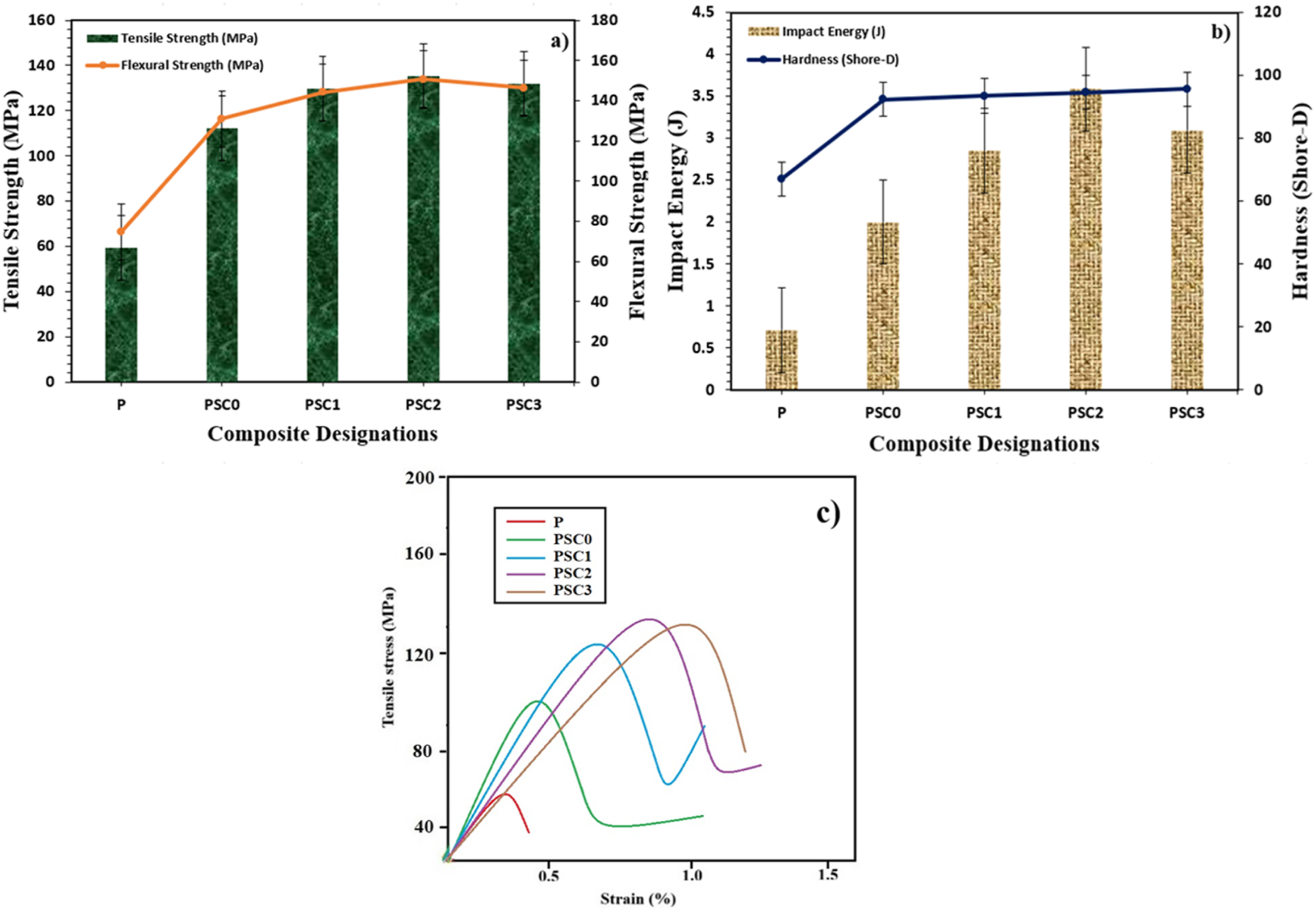
When 1 vol % silane-treated bagasse pith cellulose was introduced in PSC1, mechanical performance increased even further. Tensile strength reached 129.8 MPa, a 118.5% rise, flexural strength reached 144.1 MPa, a 92.6% rise, impact energy increased to 2.849 J, a 298% rise and hardness reached 93.5 Shore D, a 39.3% rise. These enhancements arise from the hybrid reinforcement effect created by the combination of silane-treated microfiber and silane-treated cellulose. The cellulose fills microscopic voids and strengthens the interfacial region, while the silane coupling layer on both reinforcements ensures superior compatibility and cohesive stress distribution throughout the matrix. 27
PSC2, containing 3 vol % silane-treated bagasse pith cellulose, produced the highest overall performance. Tensile strength increased to 135.3 MPa, a 128% improvement, flexural strength rose to 150.7 MPa, a 101.4% improvement, impact energy reached 3.586 J, a 402% improvement and hardness increased to 94.6 Shore D, a 40.9% improvement. This peak performance is achieved because the 20 vol% silane-treated microfiber and 3 vol% silane-treated cellulose create an optimally balanced reinforcement network. The silane modification increases wettability, enhances interfacial bonding and promotes uniform dispersion, leading to stronger mechanical interlocking, improved crack-deflection and highly efficient load transfer. 28
With 5 vol% silane-treated bagasse pith cellulose in PSC3, the mechanical performance remained high but slightly reduced compared to PSC2. Tensile strength reached 132 MPa, a 122.2% improvement, flexural strength reached 146.3 MPa, a 95.6% improvement, impact energy reached 3.091 J, a 332% improvement and hardness further increased to 95.7 Shore D, a 42.6% rise. The slight reduction in strength and toughness is attributed to the tendency of higher cellulose loading to form small agglomerates despite silane treatment, creating localized stress zones and disrupting uniform matrix flow. 29 However, the hardness increased because the additional silane-treated cellulose contributed more rigid particulate reinforcement that restricted surface deformation.
Overall, PSC2, consisting of 20 vol% silane-treated sorghum husk microfiber and 3 vol% silane-treated bagasse pith cellulose, delivered the most optimal and balanced mechanical performance. This confirms that the strongest reinforcement efficiency occurs when both fiber and filler are uniformly dispersed and chemically bonded to the PLA matrix through silane treatment.
Figure 8(a) shows the fracture surface of P, where the plain PLA matrix appears smooth and featureless with no reinforcement-induced deformation zones, indicating a brittle fracture typical of unmodified PLA. In contrast, Figure 8(b) for PSC0 reveals distinct cavities and elongated voids corresponding to fiber pull-out, confirming the presence of silane-treated sorghum husk microfiber within the matrix. The visible pull-out sites suggest that although the silane treatment improved adhesion compared to untreated fibers, the higher microfiber loading introduced multiple micro-interfaces that promote debonding under tensile loading. Figure 8(c) for PSC2 displays a more compact and uniform fracture surface, where silane-treated bagasse pith cellulose is well dispersed alongside the microfiber, with fewer voids and reduced pull-out zones. This finer dispersion and closer interfacial bonding reflect the optimal 3 vol% cellulose content, which fills micro-voids, strengthens the interface, and contributes to the superior mechanical performance of PSC2. Figure 8(d) for PSC3, however, shows agglomerated filler clusters, where excessive silane-treated cellulose accumulates into dense particulate regions. These agglomerates create stress concentration sites and disrupt matrix continuity, explaining the slight reduction in mechanical properties compared to PSC2. Overall, the SEM morphology validates the mechanical results by clearly illustrating how improved dispersion, stronger interfacial bonding, and controlled filler loading enhance composite integrity, while excessive filler encourages localized defects. SEM analysis of (a) P, (b) PSC0, (c) PSC2 and (d) PSC3 specimens.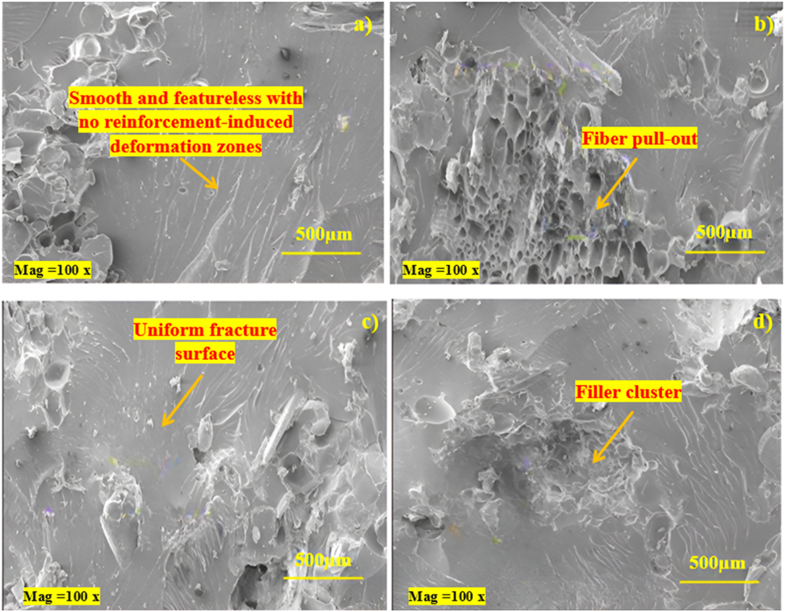
Flammability
Flammability of various composite specimens.
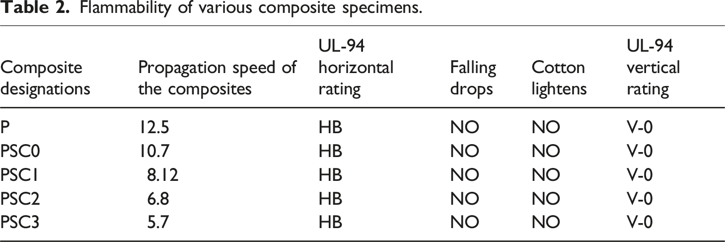
The introduction of 1 vol% silane-treated bagasse pith cellulose in PSC1 lowered the propagation speed further to 8.12 mm/s. This improvement is due to the finely dispersed silane-treated cellulose acting as a secondary char-forming agent, increasing the density of the protective carbonaceous barrier. The silane layer enhances thermal degradation stability and minimizes early volatile release, resulting in slower flame progression. 30
PSC2, containing 3 vol% silane-treated bagasse pith cellulose, displayed an even lower propagation speed of 6.8 mm/s, representing the most ideal balance of char formation and thermal shielding. At this composition, the combined contribution of silane-treated microfiber and filler produces a compact, continuous char layer during burning. This effectively reduces oxygen diffusion and heat penetration, significantly slowing flame advancement. 31
PSC3, with 5 vol% silane-treated bagasse pith cellulose, exhibited the lowest propagation speed of 5.7 mm/s. The higher cellulose content contributes more carbon-rich material for protective residue formation, leading to the slowest flame propagation among all specimens.
Despite differences in propagation speed, all composites maintained the HB horizontal classification and achieved a V-0 vertical rating with no dripping and no cotton ignition. This demonstrates that the silane-treated reinforcements not only improve the mechanical stability of the composites under heat but also encourage consistent char formation, suppress dripping behavior and prevent flaming droplets. The collective results confirm that the integration of silane-treated microfiber and silane-treated cellulose enhances the fire resistance of PLA by promoting stronger interfacial stability, char formation and flame-retarding behavior.
Swelling and degradation analysis
The swelling behavior of the PLA and its composites shows that immersion uptake increases progressively with time for all specimens, but the magnitude is strongly influenced by the presence of silane-treated sorghum husk microfiber and silane-treated bagasse pith cellulose as shown in Figure 9. The neat PLA specimen P exhibits the lowest swelling throughout the 4 weeks, increasing only from 0.109 in week 1 to 0.419 in week 4, which reflects the relatively hydrophobic nature and limited water-accessible regions of pure PLA. When 20 vol% silane-treated sorghum husk microfiber is introduced in PSC0, the swelling rises sharply to 0.887 in week 1 and reaches 3.252 by week 4. This pronounced increase arises because the lignocellulosic microfiber has an inherently hydrophilic, porous structure that draws water into its lumen and cell walls; although the silane treatment improves interfacial bonding and reduces direct fiber–matrix incompatibility, it does not eliminate the hydroxyl groups within the fiber, so the composite develops more continuous pathways for fluid ingress. The addition of silane-treated bagasse pith cellulose progressively moderates this effect. In PSC1, with 1 vol% silane-treated cellulose, swelling decreases compared with PSC0 (2.514 at week 4), as the fine cellulose particles occupy micro-voids around the silane-treated microfiber and, together with the silane-modified interface, create a denser microstructure that slightly restricts fluid penetration. PSC2, containing 3 vol% silane-treated cellulose, shows the lowest swelling among the composites, rising from 0.579 in week 1 to 2.095 in week 4. This indicates that at this loading the silane-treated cellulose is optimally dispersed, filling capillary channels and strengthening the interface so that water uptake is sufficient for fluid transport but not excessive. At 5 vol% silane-treated cellulose in PSC3, swelling increases again, reaching the highest value of 3.561 at week 4. At this higher filler content, particle crowding and possible micro-agglomeration create additional interfacial regions and micro-cracks, which, despite being silane-treated, facilitate water ingress and capillary absorption, explaining the higher swelling compared with PSC1 and PSC2. Swelling and degradation of various composite specimens.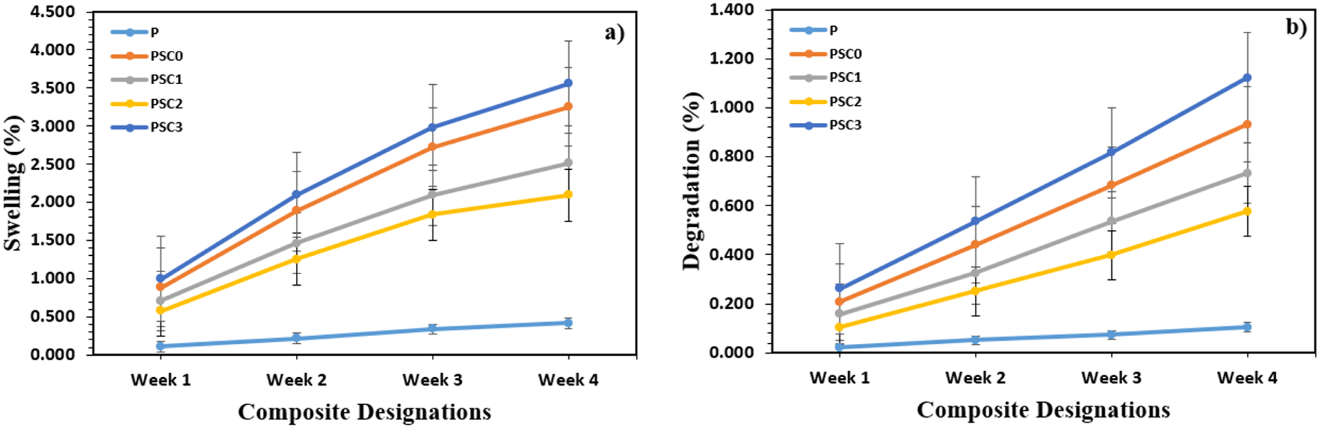
A similar trend is observed in the degradation results, where cumulative mass loss increases with immersion time and is accelerated by the incorporation of the hydrophilic, lignocellulosic reinforcements. The neat PLA specimen P shows very low degradation, increasing from 0.021 in week 1 to only 0.105 by week 4, consistent with the slow hydrolytic degradation of dense PLA under mild conditions. In PSC0, the presence of 20 vol% silane-treated sorghum husk microfiber increases degradation to 0.209 in week 1 and 0.932 in week 4. The microfiber provides additional interfaces and internal porosity that allow water to diffuse deeper into the matrix, promoting hydrolysis of PLA chains and leaching of partially degraded lignocellulosic components; silane treatment stabilizes the interface but also maintains intimate contact between phases, so once water penetrates, the enlarged interfacial area accelerates hydrolysis. The introduction of silane-treated bagasse pith cellulose moderates this effect in a similar way to swelling. PSC1, with 1 vol % silane-treated cellulose, exhibits intermediate degradation, reaching 0.733 by week 4, while PSC2, with 3 vol % silane-treated cellulose, shows the lowest mass loss among the composites, increasing from 0.105 in week 1 to 0.576 in week 4. This suggests that at 3 vol % the silane-treated cellulose helps form a compact, well-bonded network with the silane-treated microfiber and PLA, limiting crack growth and slowing the diffusion of water and degradation products, thus providing a more controlled degradation profile that is desirable for scaffold stability in bone regeneration. PSC3, containing 5 vol% silane-treated cellulose, shows the highest degradation of all the composites, rising to 1.122 by week 4. The higher filler loading, despite silane modification, likely leads to local agglomeration and microvoids that act as channels for fluid penetration and sites for preferential hydrolysis, accelerating mass loss. 32 Overall, PSC2 offers a balanced response, combining moderate swelling and controlled degradation, indicating that the synergy between 20 vol% silane-treated sorghum husk microfiber and 3 vol% silane-treated bagasse pith cellulose provides an optimal microstructure for bone scaffold applications where gradual fluid uptake and sustained structural integrity are required.
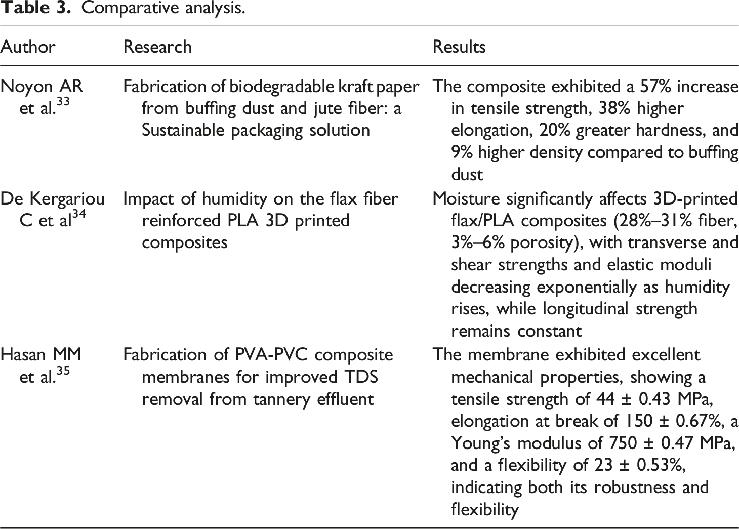
Comparative analysis
Comparative analysis.
Conclusions
In conclusion, additive-manufactured PLA composites reinforced with silane-treated sorghum husk microfiber and silane-treated bagasse pith cellulose demonstrated substantial enhancements compared to neat PLA. Among all composites, PSC2, containing 20 vol% silane-treated microfiber and 3 vol% silane-treated cellulose, exhibited the most optimal overall performance. Tensile strength increased by 128%, flexural strength by 101.4%, impact energy by 402%, and hardness by 40.9%, due to improved interfacial adhesion, uniform filler dispersion, and effective stress transfer enabled by silane modification. PSC2 also showed superior hydrolytic stability, with the lowest swelling and mass loss at week 4, attributed to its compact microstructure that limits fluid diffusion and minimizes localized polymer degradation. In contrast, PSC3, containing 5 vol% silane-treated cellulose, delivered the best flammability performance, achieving the lowest flame propagation speed due to increased char residue formation and enhanced thermal insulation from the higher cellulose content. SEM analysis further validated these outcomes, illustrating a smooth fracture surface in PLA, fiber pull-out in PSC0, uniform and dense reinforcement distribution in PSC2, and filler agglomeration in PSC3. Collectively, the results confirm that silane-treated agro-waste reinforcements significantly enhance the structural, thermal, and hydrolytic properties of PLA scaffolds, with PSC2 emerging as the most promising candidate for bone-regeneration biomaterial applications.
Limitation and future scope of the work
The reinforced PLA scaffolds have potential applications in bone-regeneration scaffolds, tissue engineering, biodegradable implants, and lightweight structural components. Industrial limitations include challenges in large-scale fiber dispersion, moisture sensitivity, scaling up 3D printing, regulatory requirements for biomedical use, and additional costs from surface treatments and processing. The future scope of this work includes optimizing the content and surface treatment of silane-treated microfibers and fillers to further enhance mechanical, thermal, and hydrolytic performance, conducting long-term in vitro and in vivo studies to assess biocompatibility and bone integration, and incorporating bioactive agents to improve osteoconductivity and antimicrobial properties. Additionally, advanced characterization under dynamic and physiological conditions, scaling up 3D printing for complex scaffold geometries, and extending this reinforcement strategy to other biodegradable polymer matrices can broaden the development of sustainable, high-performance biomaterials for bone-regeneration applications.
Footnotes
Author contributions
Joshua Toluwabori Isinkaye– Research writing and testing
Declaration of conflicting interests
The author declared no potential conflicts of interest with respect to the research, authorship, and/or publication of this article.
Funding
The author received no financial support for the research, authorship, and/or publication of this article.
Consent to participate
Yes.
Consent for publication
Yes.