
Abstract
This research examines the parametric optimization of dual-material sandwich tensile specimens produced by Fused Deposition Modelling (FDM), utilizing Polylactic Acid (PLA) for the outer shell and Carbon Fiber Reinforced PLA (PLA-CF) for the infill. Through the use of a Taguchi L9 orthogonal array design, the effects of layer height, infill density, and infill pattern on mechanical properties and fracture morphology were assessed. The results indicate that a layer height of 0.30 mm, a concentric infill pattern, and an infill density of 90% produce the highest ultimate tensile strength (41.82 MPa) and Young’s modulus (780.72 MPa), attributed to enhanced interfacial bonding and fiber dispersion. Scanning electron microscopy (SEM) analyses validate pristine PLA/PLA-CF interfaces and consistent carbon fiber distribution in optimized samples, with grid patterns notably augmenting ductility. The research concludes that the strategic selection of FDM parameters facilitates the creation of robust, lightweight, and high-strength PLA/PLA-CF sandwich structures appropriate for advanced engineering applications.
Introduction
The development of robust, customisable parts has led to a remarkable advancement in Additive Manufacturing (AM) technology in recent years. 1 AM, commonly referred to as three-dimensional (3D) printing, makes it possible to directly create complex shapes from computer models, layer by layer. 2 High automation, cheaper prices, less material waste, and the ability to create bespoke functional parts in a single step are just a few of the benefits this technology has over older ones. 3 One of the most widely used AM methods is fused deposition modelling (FDM), sometimes referred to as fused filament fabrication (FFF), due to its low cost, ease of use, and effectiveness. Thermoplastic filaments are fed through a heated extruder in the FDM process. 4 Then, using precise geometric patterns determined by instructions from Computer-Aided Design (CAD) software, the molten material is deposited layer by layer. The quality, mechanical performance, and ultimate functioning of FDM-printed items are significantly impacted by a number of process parameters. 5 This implies that careful optimisation and selection are required. Important variables that impact a part’s characteristics include layer height (LH), infill density (ID) and Infill pattern (IP), raster angle, printing speed, and extrusion (nozzle) temperature.6,7
The most popular polymer in FDM is polylactic acid (PLA), which is made from renewable resources like sugarcane or corn starch and is easy to work with, cheap to make, and easily decomposes. 8 Pure PLA has its own disadvantages, such as being somewhat brittle and having reduced mechanical strength, which makes it less appropriate for high-performance or load-bearing applications, despite these advantageous qualities. 9 Researchers frequently use reinforcing fillers to address these mechanical issues. 10 Carbon fibre (CF) is a popular choice for reinforcement because it is lightweight, better holds its shape, and adds strength and stiffness without adding undue weight.11,12 Compared to clean PLA, the resulting composite, Carbon Fiber-Reinforced PLA (PLA-CF), frequently exhibits much better tensile strength and elastic modulus, demonstrating notable improvements in mechanical performance.13,14
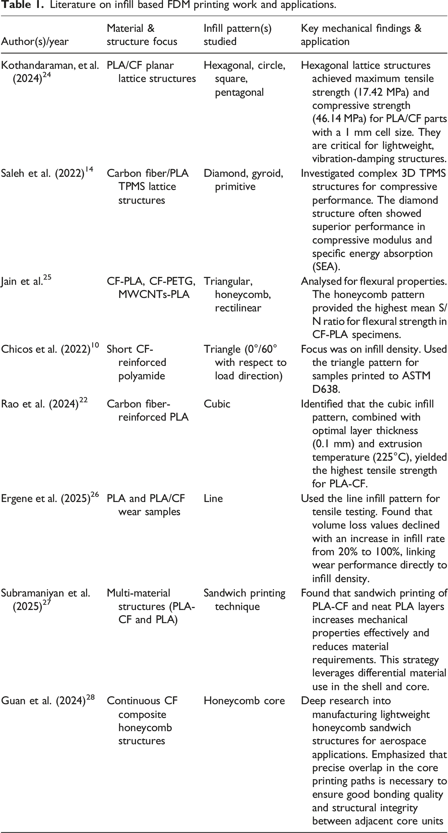
Literature on infill based FDM printing work and applications.
Based on the above literature, it is observed that a gap remains in research on the combined optimization of FDM parameters for dual-material specimens, such as PLA with PLA-CF infill hybrid specimens, using efficient experimental designs. 17 Specifically, there have been few studies that have utilized Taguchi L9 orthogonal array to systematically investigate how various FDM parameters impact the tensile strength and surface morphology of different material configuration. 28 It is necessary to fill this gap in order to provide comprehensive instructions on how to create high-performance, structurally tailored composites.15,25 Thus, this study utilizes dual-material FDM technology to produce and characterize hybrid PLA/PLA-CF samples. To systematically examine the influence of critical FDM processing parameters on the mechanical properties of the hybrid specimens, a robust Taguchi L9 experimental design 27 is employed provides detailed information of the influence of process parameters on mechanical properties.15,29
Material and method
Material pre-processing
Figure 1 explains a detailed experimental method for making and testing a 3D-printed tensile sample using FDM on a Bambu X1 Carbon printer. Before the 3D printing procedure, rigorous material pre-processing protocols were implemented to guarantee the integrity of the printed specimens. The PLA and PLA-CF filaments were preserved in vacuum-sealed containers containing desiccants to avert moisture absorption, which is recognized to induce hydrolysis and void formation during extrusion. The PLA filament (density 1.26 g/cm3, diameter 1.75 mm) is dried for 8 h at 60°C, and the PLA-CF filament (density 1.22 g/cm3, carbon fibre reinforced with 5–15% CF content) is dried for 12 h at 75°C in a closed chamber. This removes any moisture that has been absorbed and stops hydrolytic degradation, bubbling, and poor layer adhesion during printing. The longer drying process for PLA-CF at a higher temperature is necessary because the fibre-matrix interfaces make the material more moisture-sensitive, which facilitates better bonding between the fibers and matrix.
30
Literature show pre-processing strategy aligns with established protocols for composite AM, as detailed by Arunachalam et al.
31
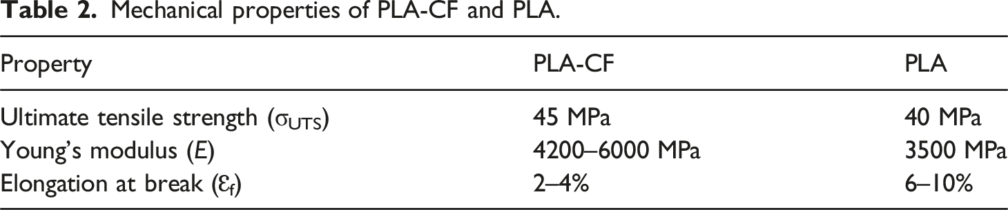
After pre-processing, tensile specimens are formed using the Bambu X1 Carbon printer, which features automatic filament switching. The top and bottom layers, as well as the wall structures, are made of PLA, and the core infill material is PLA-CF. This creates a hybrid structure that leverages the flexibility and dimensional accuracy of PLA, as well as the improved stiffness and strength of PLA-CF. The printed specimens are subjected to standardised tensile testing utilising a universal testing machine equipped with regulated load application and continuous data collection. After the test, scanning electron microscopy (SEM) is used to look at the fractured specimens to find out more about the fracture morphology, the quality of the interlayer fusion interface, the CF dispersion, the fibre pull-out mechanisms, and the formation of voids. This delivers us with main effect plots and single-to-noise (S/N) ratio plots, which help us recognize the optimal combinations of parameters that yield the highest tensile strength with the least variation. To finish, do a full comparative analysis. Table 2 shows the mechanical properties of the PLA and PLA-CF filament. Experimental workflow for 3D-Printed PLA and PLA-CF tensile sample Fabrication, tensile testing, microstructural characterization, and statistical optimization. Mechanical properties of PLA-CF and PLA.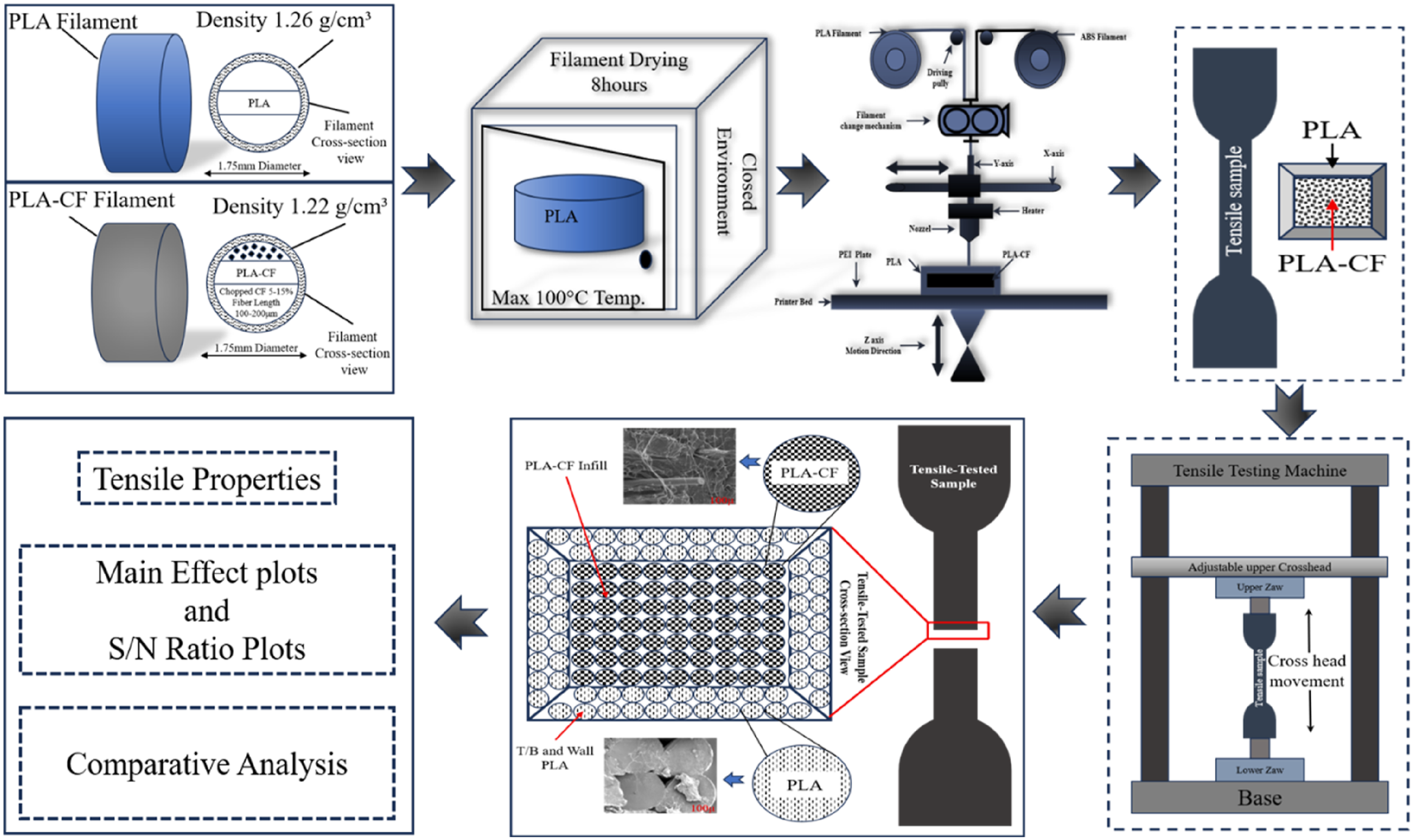
Printing parameter
Constant parameters.

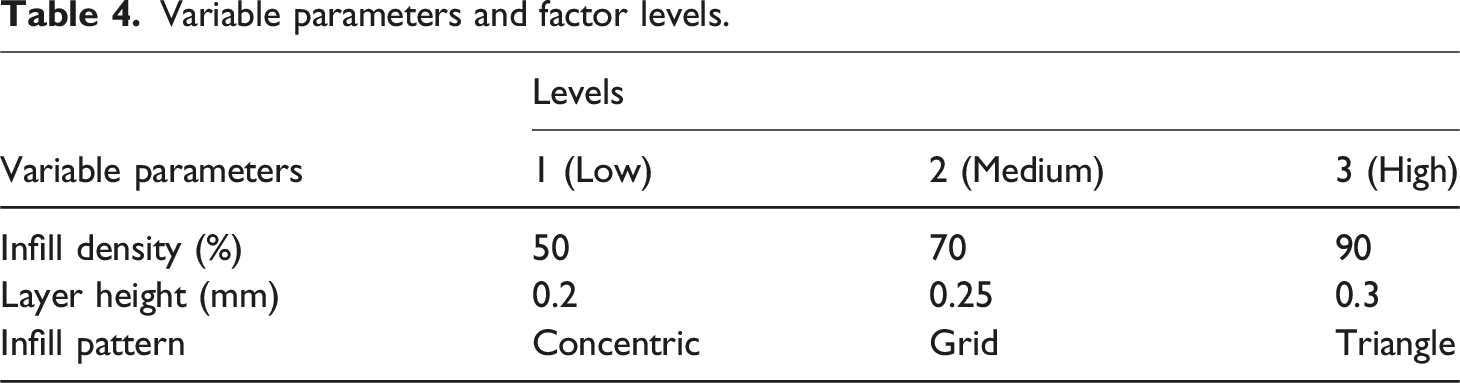
Variable parameters and factor levels.
Experimental design and sample preparation
Taguchi L9 orthogonal array design matrix.
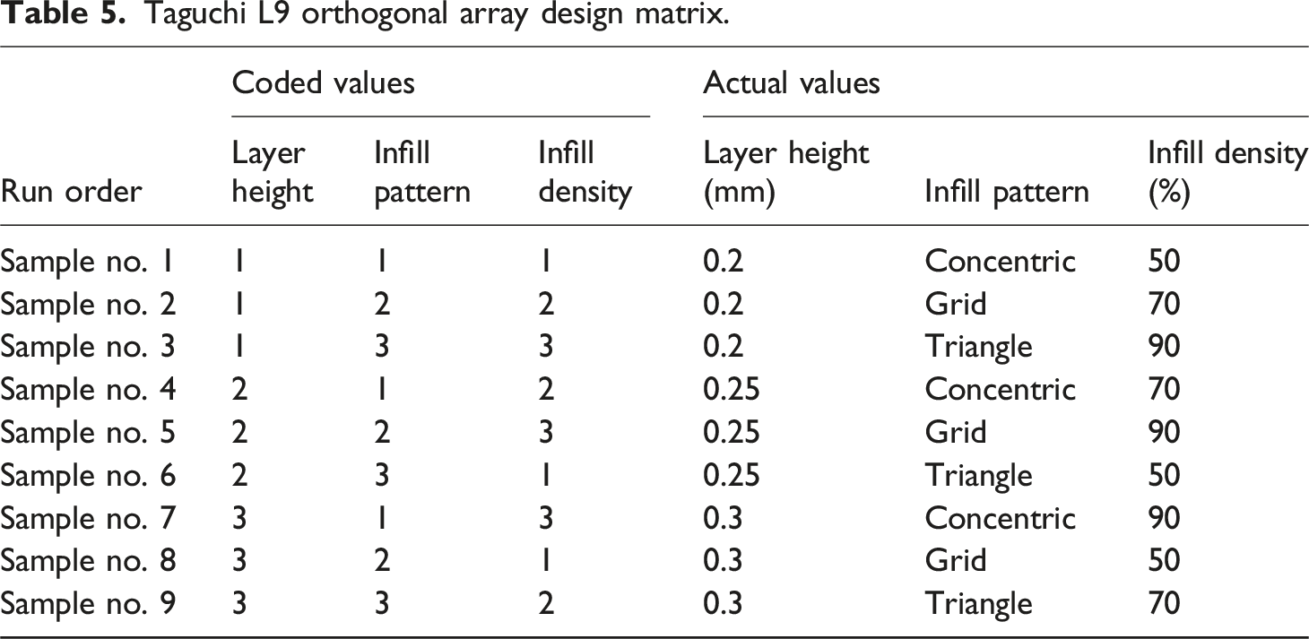
Figure 2 illustrates the full 3D printing process and tensile testing setup for specimens. It starts with digital design in AutoCAD software, where the ASTM D638 Type IV dogbane geometry is modelled exactly according to standard specifications. This CAD design is saved as an STL (Stereolithography) file, which is the standard polygonal format required by 3D printers to operate. Then, the STL file is opened in Bambu Slicer software, which slices the 3D geometry layer by layer at the specified layer height. This turns the design into a toolpath that the Bambu X1 Carbon printer can follow. The Bambu Slicer interface enables you to enter process parameters from Tables 2 and 3 into the slicing software in a systematic manner. These include the temperature of the nozzle and bed, the speed and acceleration of the print, and the choice of material (PLA for the outer shell and PLA-CF for the infill). The slicer then creates an optimised infill pattern with the correct geometry, which controls how the PLA-CF material is inserted inside the outer PLA shell. After all the settings are set, the Bambu Slicer turns the sliced geometry into G-code. This is a programming language that machines can read, which includes motion commands (X, Y, Z coordinates), extrusion parameters, and temperature settings that the printer’s control firmware uses to create objects. Figure 2(a) shows the Bambu X1 Carbon printer working in real time to make specimens. It displays the live printing process, including filament extrusion and layer deposition. The three infill pattern geometries that the slicer can use are shown in Figure 2(b): concentric, triangular, and grid. Figure 2(c) shows a three-dimensional view of a prepared sample. The outer surface is labelled as “Outer Side PLA,” and the inside is labelled as “Inside PLA-CF.” Figure 2(d) shows all nine tensile specimens (samples 1–9) that make up the full Taguchi L9 orthogonal array experimental design. Each specimen is associated with a distinct set of parameter combinations, as listed in Table 4. Experimental fabrication and testing setup: (a) 3D printing of tensile specimens, (b) infill pattern geometries, (c) 3d cross-sectional view of prepared tensile sample, (d) Z010 universal testing machine with integrated control unit, (e) before loading (f) set of 9 tensile specimens and (g) after testing state showing sample failure.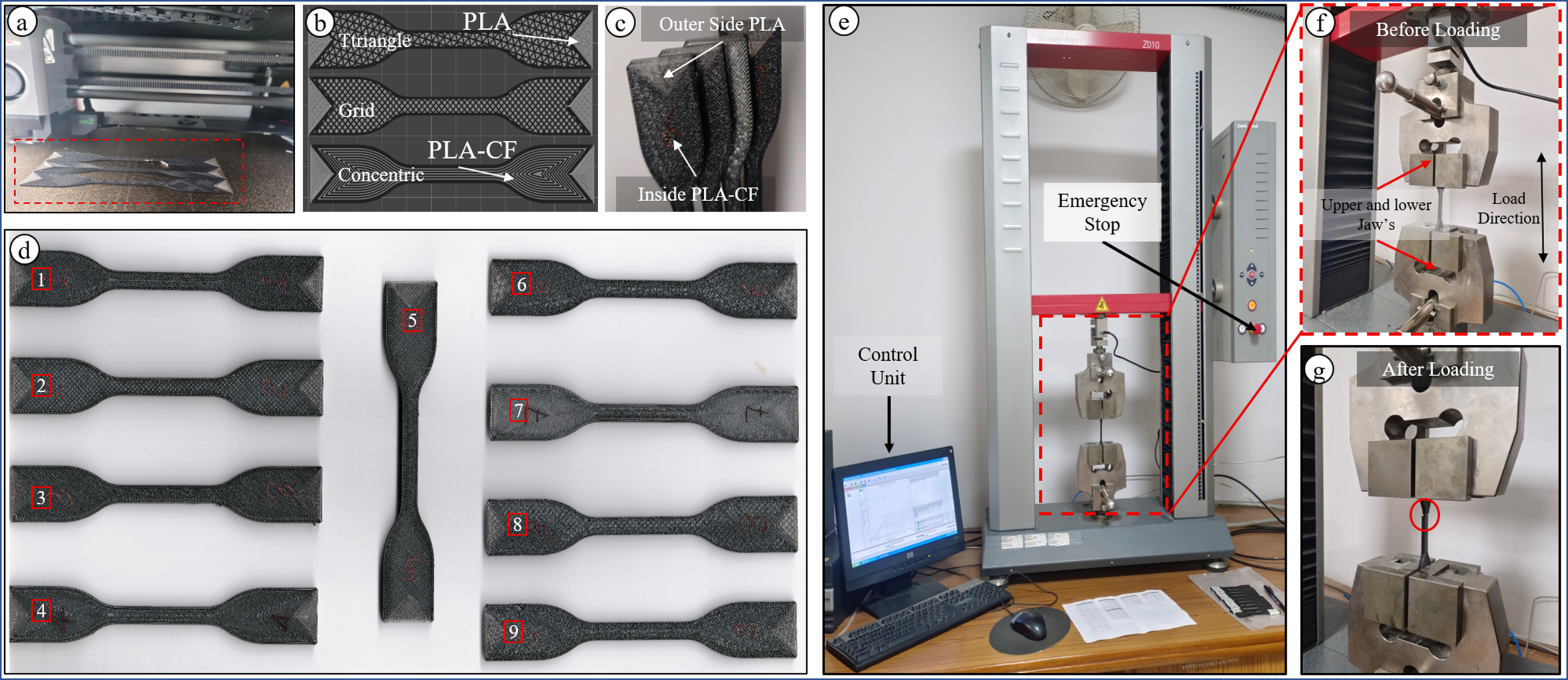
Result and discussion
Tensile testing results
Mechanical properties of 3D-printed dual-material tensile samples: young’s modulus, ultimate tensile strength, and elongation at failure.
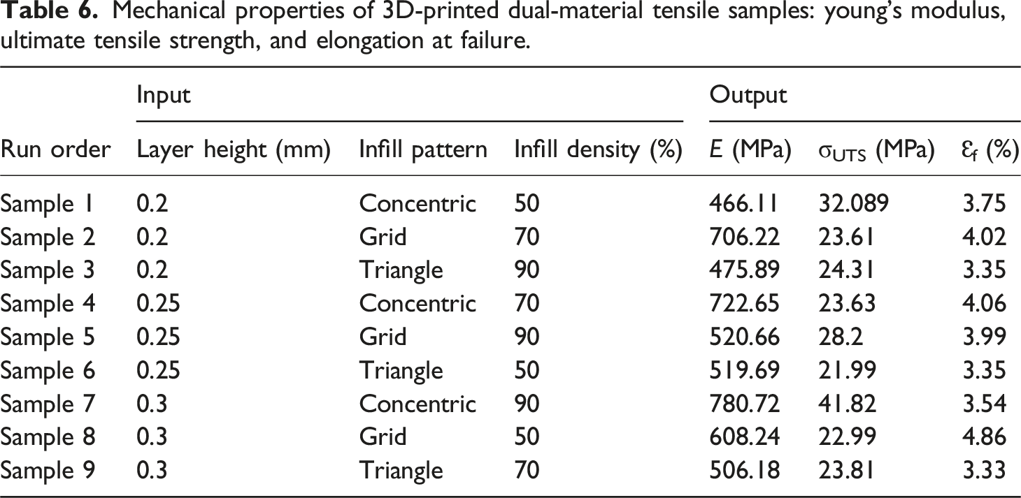
Figure 3 shows response surface methodology contour plots illustrating the dependence of layer height and infill density on E (MPa) (Figure 3(a)), σUTS (MPa) (Figure 3(b)), and Ɛf (%) (Figure 3(c)) across the Taguchi L9 experimental matrix. Maximum E (∼780 MPa) is reached at 0.30 mm layer height with 90% infill density. This is because layer height lowers the number of interlayer interfaces and weak bonding zones, while a higher infill density increases the volume fraction of stiff PLA-CF.
13
σUTS reaches its highest point at 41.82 MPa for Sample 7 with 0.30 mm layer height, concentric pattern and 90% infill density. This indicates that the best layer height enables better polymer chain diffusion bonding at the PLA/PLA-CF interface, thereby making stress transfer through the Hybrid structure more efficient. A thin layer of layer height (0.20 mm) also lowers the E value (∼466–706 MPa), and the strength changes due to the excessive number of interlayer interfaces, which cause porosity and incomplete fusion bonding. Ɛf reaches its highest point at 4.86% with a 0.30 mm layer height and a lower infill density (50%). This means that thicker layers with less rigidity can bend and stretch before breaking, while a high infill density (90%) makes plastic deformation harder and makes the material more brittle.
5
Contour plots showing the influence of layer height and infill density on (a) E, (b) σUTS and (c) Ɛf (%) for PLA-CF/PLA composite specimens.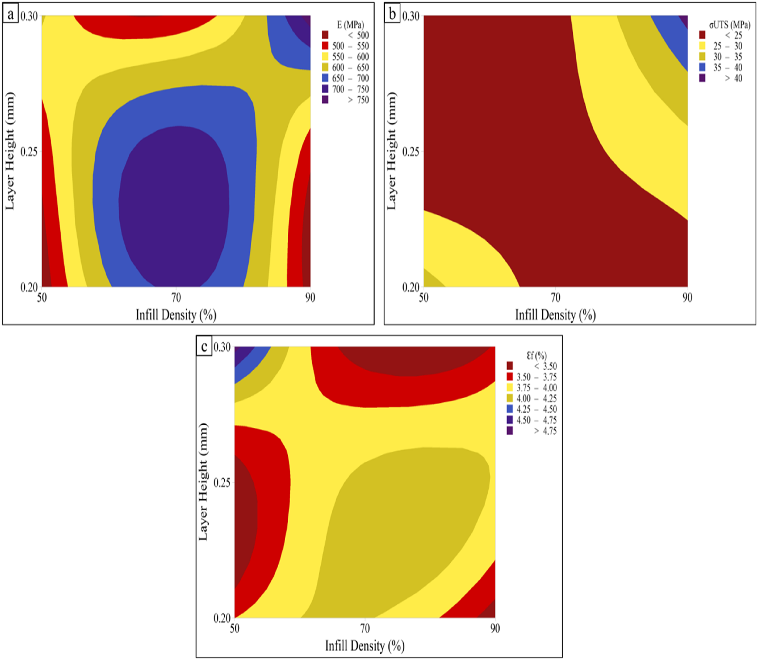
Stress–strain curves for the different layer-height are shown in Figure 4. Samples printed with a 0.2 mm layer height (samples 1–3 in Figure 4(a)) show dispersed mechanical performance due to excessive interlayer interfaces. Their σUTS ranges from 23.61 to 32.09 MPa, and E varies from 466 to 706 MPa. The 0.25 mm layer-height samples (samples 4–6 shown in Figure 4(b)) exhibit intermediate mechanical behaviour, representing a transitional regime. In contrast, 0.3 mm layer-height samples (samples 7–9 shown in Figure 4(c)) achieve superior mechanical properties. Sample 7 records the highest performance with a σUTS of 41.82 MPa and E of 780.72 MPa. In FDM manufacturing of composites, layer height directly controls the quality of the interlayer bonding by controlling the thermal history and the time it takes for polymer chains to diffuse.
1
The infill pattern geometry (concentric, grid, or triangle) affects how stress is distributed and how well loads are transferred. Infill density controls the high-modulus PLA-CF volume fraction within the low-modulus PLA matrix. Intermediate densities (50–70%) strike a balance between strength and ductility, whereas excessive density (90%) renders the material brittle by placing too much stress on the structure. These experimental results are consistent with the literature on FDM-printed composites by, validating that optimal mechanical properties are achieved through the integration of reinforcement content, interlayer bonding quality, and interfacial stress transfer mechanisms in the additive manufacturing of polymer composites.
22
Stress-strain curves of 3D-printed PLA-CF/PLA Tensile specimens at varying layer heights (a) 0.2 mm, (b) 0.25 mm, and (c) 0.3 mm.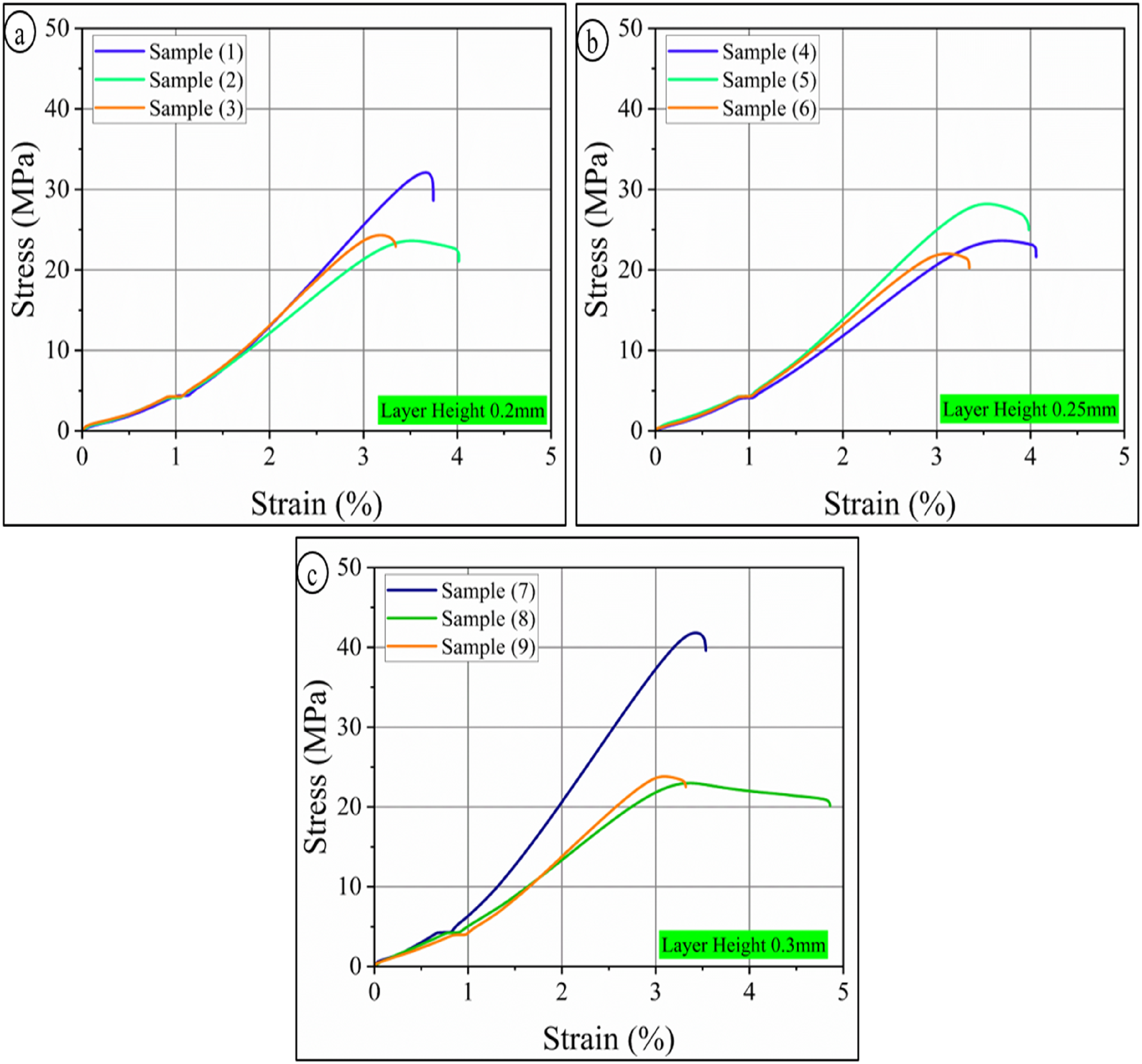
Main effect plots
Main Effects Plot of FDM parameters on comprehensive interpretation of E (MPa), Ɛf (%) and σUTS (MPa) is shown in Figure 5(a)–(i). Figure 5(a)–(c) shows that all process factors are clearly sensitive to changes in E (MPa). For example, infill density increases E (MPa) from approximately 535 MPa (50%) to approximately 595 MPa (90%). Infill pattern exhibits concentric geometry, achieving maximum stiffness compared to the triangle pattern, and layer height shows progressive enhancement from 0.2 mm to 0.3 mm. The steady rise in infill density indicates that the PLA-CF content has increased, which directly makes the composite stiffer by adding more fibers to the volume. Concentric infill pattern is better than grid and triangle infill pattern because its circular loop structure works well with tensile loading, spreading stress evenly without any concentration points. Triangular patterns, on the other hand, create geometric stress risers that make the material less stiff. Layer height (0.30 mm) reduces interlayer fusion interfaces, which allows for better polymer chain inter-diffusion at the PLA/PLA-CF boundary and less microstructural porosity that would otherwise harm the E (MPa). The ∼85 MPa increase in stiffness from a layer height of 0.2 to 0.3 mm demonstrates the importance of the layers bonding well for the composite to function effectively.
34
Main effect plots for showing variation of (a–c) young’s modulus, (d–f) elongation at failure (%), and (g–i) σUTS.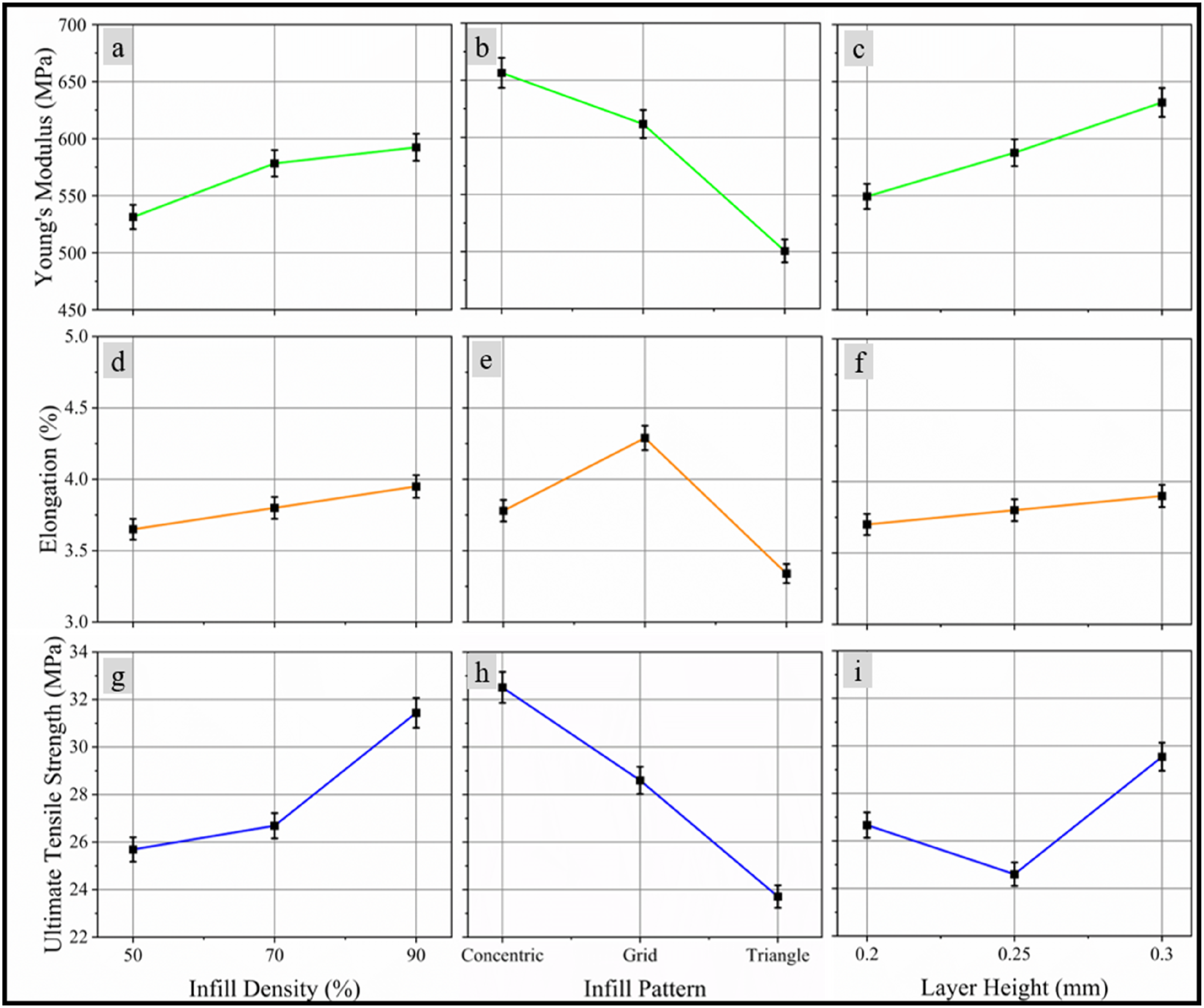
Figure 5(d)–(f) illustrates Ɛf (%) at different parametric dependencies compared to modulus and strength. It is not very sensitive to changes in infill density and layer height, but it is very sensitive to changes in infill pattern geometry. The grid arrangement gives the most ductility, while concentric and triangular patterns give the least. This pattern-dependent behaviour shows that the ability to deform docilely is mostly determined by how well internal stress is distributed and how well the PLA matrix remains intact, rather than by the quality of the interfacial bonding. Grid patterns are effective at redistributing stress across multiple load paths, allowing for gradual plastic deformation before catastrophic failure. Instead, concentric and triangular geometries concentrate stress along preferred pathways, which leads to brittle fracture. 7
Figure 5(g)–(i) for σUTS shows a non-linear optimisation path. Infill density shows small strength gains, infill pattern shows concentric geometry reaching maximum strength versus the triangle pattern minimum, and layer height shows peak performance at 0.3 mm with lower values at 0.25 mm. The concentric pattern’s tensile strength stems from the fact that the CF is perfectly aligned perpendicular to the direction of the load, allowing for direct load transfer through the high-modulus reinforcement phase without any stress-concentrating geometric discontinuities. On the other hand, triangular patterns create inefficient stress pathways and preferred sites for starting fractures, which lowers the ability to bear weight. The layer height effect exhibits a non-monotonic trend, where 0.3 mm improves interfacial bonding by increasing the thermal residence time, which encourages molecular chain interdiffusion of PLA/PLA-CF. 34
Single to noise (S/N) ratio plots
Figure 6 S/N ratio plots showing how infill density, infill pattern and layer height affect the E, Ɛf (%) and σUTS of PLA/ABS sandwich specimens. The trends in the S/N ratio for E in Figure 6(a)–(c) show that the infill pattern is the most important factor that controls how consistent stiffness is. The concentric geometry has the highest S/N ratio, which is better than both the grid and the triangle. This means that concentric patterns give the most consistent and repeatable modulus values. Infill density also has an effect on stiffness robustness; values increase from 50% to 70% but drop significantly at 90%. This drop indicates that very high densities cause variability because the PLA-CF is not evenly distributed, which increases the likelihood of defects. The layer height varies from 0.20 mm to 0.30 mm makes the stiffness more robust by reducing interlayer defects and making the bonding more uniform.
23
Signal-to-noise ratio main effects plots for (a–c) young’s modulus, (d–f) elongation, and (g–i) UTS.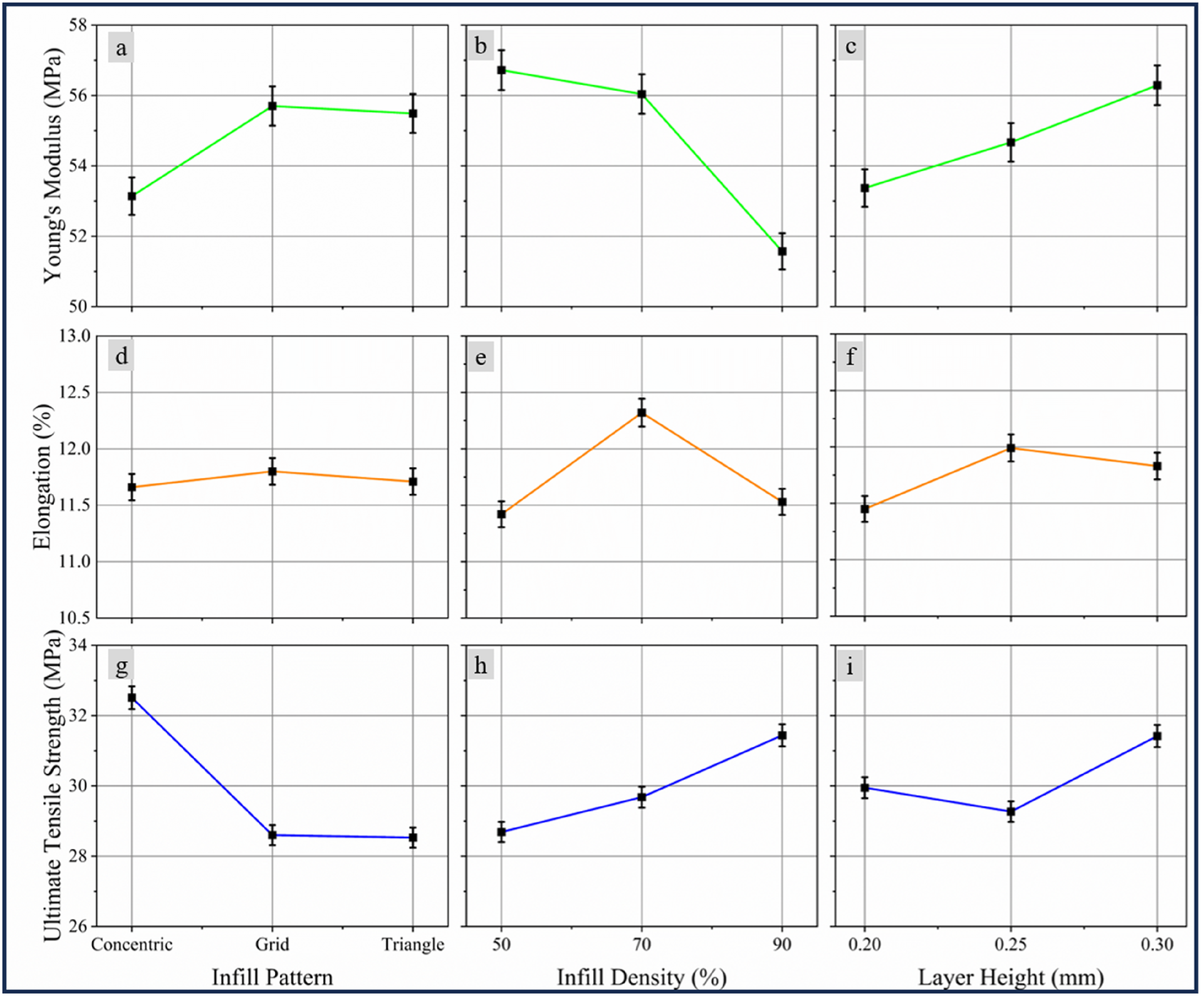
The S/N ratio plots for Ɛf (%) in Figure 6(d)–(f) show a distinctly different optimization path, which is primarily based on how the material deforms, rather than its stiffness or strength. The infill pattern controls the consistency of ductility, and grid geometry has the highest S/N ratio, surpassing concentric and triangular geometries. The infill density shows another peak at 70%, indicating that moderate levels of reinforcement maintain good matrix continuity and improve strain uniformity. Instead, extremes at 50% and 90% make the matrix less reliable. Layer height has only a small effect, with S/N ratios ranging from approximately 11.4 to 12.0 dB and a slight maximum at 0.25 mm. This shows that ductility robustness is not very sensitive to interlayer thickness. These trends indicate that the best elongation occurs with grid infill pattern and an Infill density of 70%, while the best stiffness and strength robustness are achieved with concentric patterns and thicker layers. This underscores the necessity for application-specific parameter optimisation, given that PLA/PLA-CF sandwich composites demonstrate distinct variability in modulus, strength, and ductility. 22
Figure 6(g)–(i) shows that σUTS (MPa) reacts differently to changes than the modulus does. Infill pattern is important again, and concentric geometry gives the best S/N ratio, followed by grid and triangle. This indicates that the tests are both stronger and more consistent from one test to the next. The infill density has a strong non-linear effect, with a 70% density providing the most stability, while densities of 50% or 90% result in less stability. Layer height also affects the strength of something, with 0.20 mm being the weakest, 0.25 mm being slightly stronger, and 0.30 mm being the strongest. These results show that thicker layers and concentric infill pattern make strength behaviour more stable and predictable. The best robustness for σUTS is achieved with a 0.30 mm layer height, concentric infill pattern, and 70–90% infill density, which aligns with the findings in the main effect plots. 11
Morphology and fractography
The examination of the fractured interface, illustrated in Figure 7, provides essential insights into the failure mechanisms that are directly linked to the assessed mechanical performance of the printed composites. Figure 7(a) and (b) (Sample 6), with a lower σUTS of 21.99 MPa and Ɛf of 3.35 (%), Table 5, shows a fracture edge with a rougher surface and a more visible separation between the neat PLA outer shell and the PLA-CF infill.
26
This morphology suggests inadequate interfacial bonding and probable micro void formation at the PLA/PLA-CF interface, a significant shortcoming frequently observed in FDM, characterised by poor adhesion between deposited layers. A significant amount of research supports the notion that weak bonding interfaces and internal voids significantly reduce the mechanical strength of FDM composites, resulting in reduced ductility and tensile strength. On the other hand, Figure 7(c) and (d) (Sample 7), which had much better properties (σUTS = 41.82 MPa and Ɛf = 3.54 (%) Table 5), shows a much cleaner and straighter line of separation between the PLA shell and the PLA-CF infill layers. This more stable fracture line suggests that the interface is stronger, which is directly related to the increase in ultimate strength and stable elongation observed. This improvement in performance is attributed to the printing conditions that facilitate easier interaction between polymers.
20
Fracture morphology of PLA/PLA-CF tensile samples (a): fractured interface detail for sample 6 showing PLA outer and PLA-CF infill zones, (b): full view of fractured sample 6, (c): full view of fractured sample 7, (d): fractured interface detail for sample 7, showing clear separation between PLA and PLA-CF.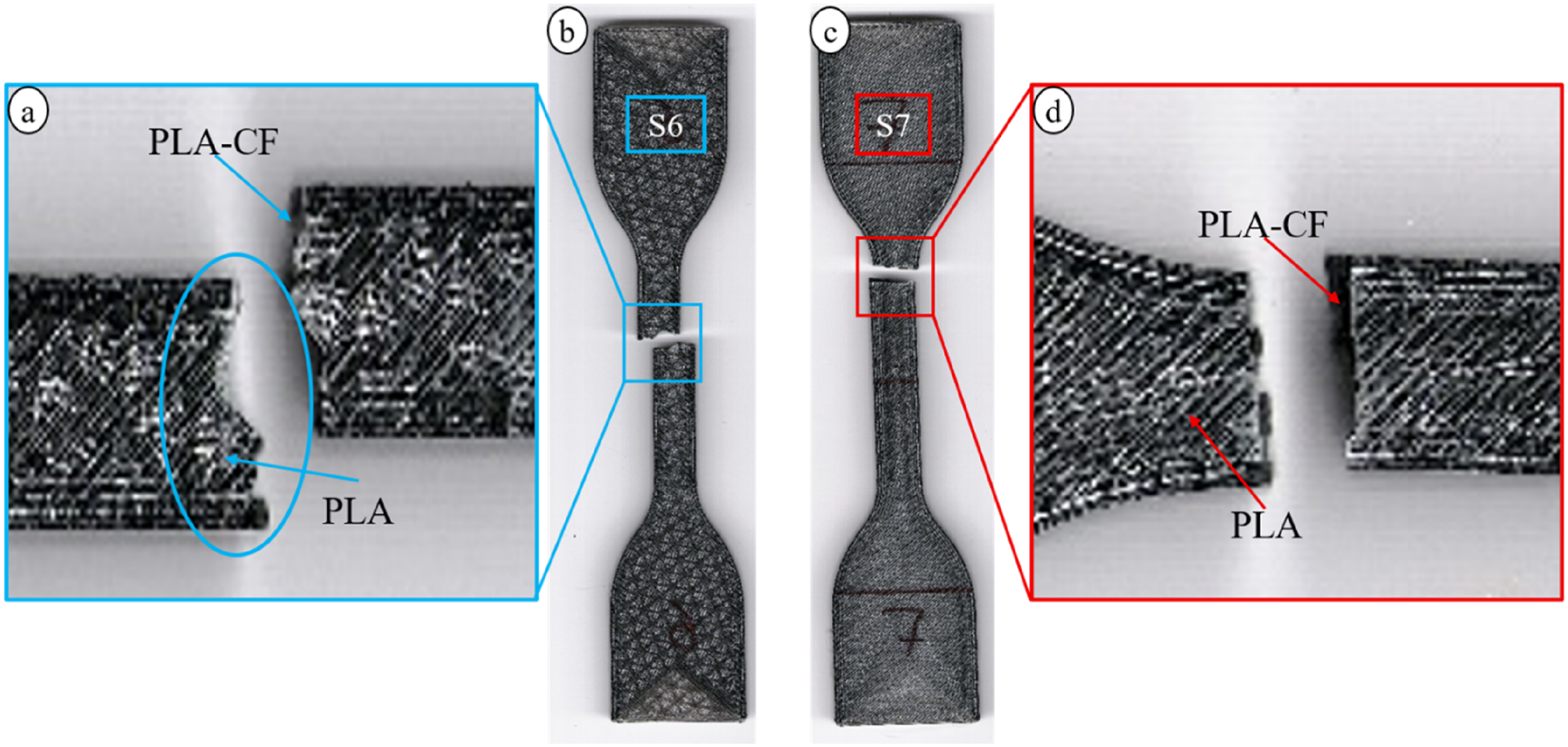
The Fractography of Sample 7, supported by SEM analysis (Figure 8), confirms its enhanced mechanical performance, attributed to optimized fractography and inter-material bonding, a crucial factor that frequently constrains the mechanical performance of FDM composites. Figure 8(a) gives an overview, and Figure 8(b) gives a more detailed view of the interface between the smooth PLA outer shell and the rough, fibre-rich PLA-CF infill. Close contact with few gaps, voids, or cracks is very important because it indicates that multi-material polymers diffuse and bond well at the interface. This result successfully solves the common problem of poor adhesion and micro void formation at the fibre-matrix interface and between layers in FDM PLA-CF parts. This indicates that bond quality is crucial for the strength of composites.
15
Figure 8(c) also shows characteristic fracture features at a higher magnification. These features include well-dispersed carbon fibres in the matrix, as well as signs of fibre pull-out and matrix deformation. These mechanisms are signs of a tough, well-integrated composite. They demonstrate that the material can absorb energy in a controlled manner during loading, rather than simply breaking easily. Finally, Figure 8(d) illustrates the internal load-bearing structure, which features regularly spaced filament gaps (engineered voids) due to the use of a concentric infill pattern. This structural design strikes a balance between mechanical strength and material efficiency. This is a deliberate strategy, similar to those used in optimized sandwich or lattice structures, that improves the strength-to-weight ratio while maintaining the ability to transfer loads.
28
SEM images of fractured tensile specimen (sample 7), (a) overall fracture morphology, (b) uniform filament structure with minimal voids, (c) high magnification image showing fibre pull-out and matrix tearing, (d) compact filament surface with localized brittle fracture.
Figure 9 shows SEM images that are very important for Fractography. Figure 9(a), magnified 100 times, shows the area where the PLA outer shell meets the coarse PLA-CF infill. The clear line indicates that the PLA and PLA-CF layers have fused together well, confirming that multi-material fusion was successful. The difference in shape between the smooth PLA and the rough, fibre-rich PLA-CF is clear. This is because carbon fibres were added to the infill area. Figure 9(b), shown at 500× magnification, illustrates the area where the layers adhere to each other. The visualisation of small gaps and a continuous interface indicate strong bonding, probably because the polymer chains are tightly intertwined between the layers that were deposited. This strong adhesion is crucial for enhancing mechanical strength. Numerous studies have demonstrated that poor interfacial bonding and inadequate polymer diffusion are two primary reasons for the low tensile strength of FDM parts. When reinforcement layers are put on top of full PLA layers.
15
SEM images showing interlayer bonding: (a) well-fused layer interface with strong adhesion, (b) close view showing continuous bonding and limited voids, (c) high magnification displaying fibre imprints and matrix deformation.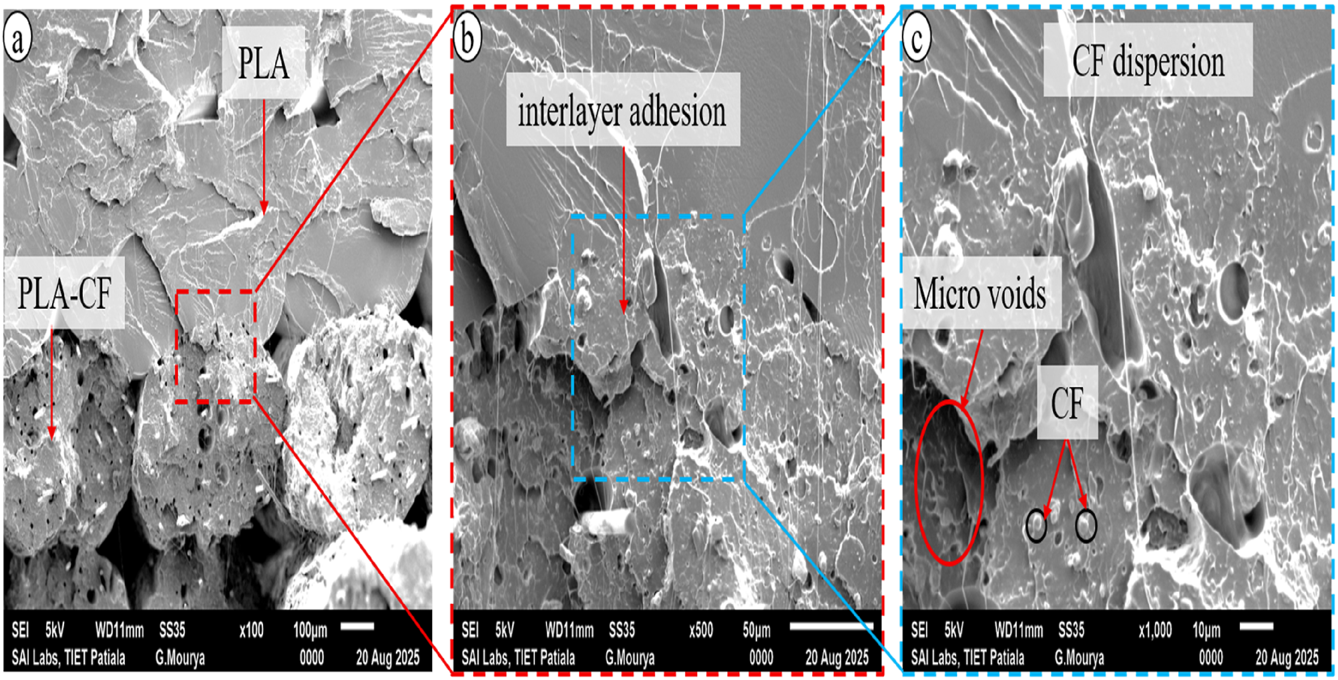
Figure 9(c), captured at a higher magnification (×1000), reveals the internal structure, confirming that the carbon fibres are well dispersed throughout the PLA matrix. The picture also shows features of fibre pull-out and micro voids around the fibres. These micro voids can cause stress to build up, which usually makes things less ductile. However, the presence of fibre pull-out indicates that a toughening mechanism is in place, absorbing energy during fracture. The image shows that the material is evenly spread out and well-bonded, which differs from reports of a poor bonding interface or clumping of carbon fibers, which typically weakens the ultimate tensile strength of reinforced parts. 14
Figure 10(a), illustrates how the strategic architecture of the grid infill pattern provides strong evidence explaining the superior ductile behaviour of Sample 8 (Ɛf = 4.86%). The critical PLA-CF infill layer interface is shown in Figure 10(b), where stress is distributed throughout the interconnected lattice rather than concentrating along a single axis. At higher magnification, Figure 10(c) shows the pullout of individual carbon fibers in the PLA matrix, which promotes energy absorption and fibre-matrix interfacial sliding. The most important aspect is observed in Figure 10(d) which shows the hierarchical fracture morphology across the different material zones. It shows ductile dimpling and fibrous tearing in the infill regions, staggered crack propagation through grid nodes that blunt the crack tip by acting as mechanical barriers, and localized matrix deformation with micro-void coalescence all of which are signs of progressive plastic failure as opposed to brittle fracture. This microstructural design is in stark contrast to Sample 7 (Concentric), where low energy absorption and homogenous, unstable crack propagation are produced by aligned fiber orientation parallel to the loading axis. The Grid design permits dispersed energy dissipation across multiple infill-shell interfaces by using each intersection junction as a localized stress concentration point undergoing controlled plastic deformation through matrix yielding, interfacial sliding, and ligament rotation. SEM fractographic analysis of sample 8: (a) tensile tested specimen, (b) PLA-CF infill interface with stress redistribution, (c) high magnification shows carbon fibers with partial debonding, (d) high magnification revealing PLA-CF and PLA with ductile fractography.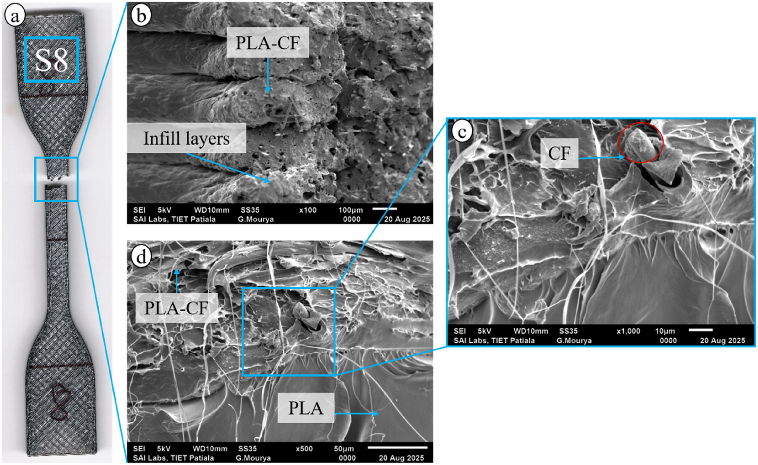
Comparative analysis and literature correlation
The testing data show that Sample No. 7 had the best mechanical performance, with a maximum σUTS of 41.82 MPa and an E of 780.72 MPa. This was achieved by combining a 0.3 mm LH, a Concentric IP, and a 90% ID. Sample 6, on the other hand, had the weakest strength, σUTS = 21.99 MPa.
Analysis of optimal parameters
Infill density: A large part of what makes Sample 7 work is the high. To achieve the optimum mechanical performance from the FDM process, you need to achieve the maximum feasible filling densities. 17 Literature supports that increasing the amount of material used to print the inside of the part, known as filling density, is necessary to reduce internal voids and porosity, which are known to be areas of failure. One study, for instance, found that increasing the infill density resulted in wear tests losing less volume. 15 Infill pattern: The Concentric Infill pattern was crucial in making Sample 7 as strong as possible. The Infill pattern is one of the most crucial settings that affects the quality of items produced with FDM. The concentric pattern typically makes the material stronger because it aligns the printed filaments with the borders of the specimen, allowing the material channels to better withstand uniaxial tensile force. This impact is highly essential since it is necessary to fix defects and strengthen the composite core to improve its performance. 17 Layer height: The maximum tested Layer height (0.3 mm) was the best strength for Sample 7. Layer height is a key process parameter that directly affects the mechanical characteristics. Some research suggests that reducing Layer height can improve the attachment of beads to layers, but it’s challenging to achieve the optimal Layer height level, and its effect is often coupled with other factors, such as infill density. The success of Sample 7 illustrates that the height and the Concentric pattern worked effectively together to help fusion and fix internal problems.22,23
Mechanical properties in the context of literature
People who wish to make FDM stronger typically utilise PLA-CF composites. PLA is a biodegradable polymer that is receiving considerable attention in research, particularly in 3D printing and FDM. E: Stiffness Sample 7’s high E = 780.72 MPa is in accordance with the objective of making composites stronger. 3 To make PLA filaments firmer and operate more effectively in general, synthetic fibers like carbon fibers are added. Failure Mechanism and Porosity: The poor mechanical performance exhibited in other samples, notably Sample 6, which has a low Infill density, is directly connected to faults and deterioration of the material. Studies reveal that FDM products with low mechanical qualities often have significant porosity, poor compaction, and limited adhesion between layers. When reinforcing materials clump together and don’t spread out, it might cause failure areas to occur. Controlling the printing settings changes the material’s interior porosity and interfacial bond strength, which in turn determines how the material will behave mechanically. 32 Structures: The rationale behind multi-material printing, such as sandwich printing of PLA-CF and PLA filaments, is that it can make the mechanical qualities better and use less material to attain the same performance. 19 Additionally, structural techniques such as honeycomb sandwich constructions need to be manufactured cost-effectively, which typically entails carefully planning the path and establishing parameters to ensure the unit structure remains stable and its structural integrity improves. 4
Our results about the critical importance of parameter optimization are consistent with current research on Carbon Fiber-Reinforced PLA. In literature, Dhouioui et al. (2025) examined how layer thickness, printing speed, and raster angle affected PLA-CF performance. 35 They found that a raster angle greatly improves strength and stiffness, especially when paired with thinner layer heights (0.3 mm as opposed to 0.4 mm), since this arrangement promotes fibre alignment with the load. 35 By successfully aligning fibers along the stress lines, Sample 7 (Concentric pattern, 0.3 mm layer height) demonstrated higher mechanical performance, which is consistent with our testing results. Additionally, it was shown by Magri et al. (2021) that process variables such infill line direction and nozzle temperature are critical to mechanical performance. 2 Their research showed that because of improved fibre use and decreased raster delamination, certain orientations produce noticeably better tensile qualities than normal orientations. Our results also show a trade-off between strength and elongation depending on the infill approach used, which is consistent with Dhouioui et al. (2025), who observed that adding carbon fibers increases stiffness but may decrease ductility. 35 According to these evaluations, maximizing the potential of FDM-printed composite materials always requires optimizing the deposition path to Favor fibre alignment.36,37
Conclusion
This study systematically examined the process–structure–property relationships in FDM-printed PLA shell/PLA–carbon fiber infill sandwich tensile specimens using a Taguchi L9 experimental framework. By integrating parametric optimization with fracture-surface analysis, following conclusions can be drawn: • Infill pattern is the most influential design parameter, with the concentric infill configuration exhibiting superior load-bearing capacity and stiffness. The enhanced tensile strength (41.82 MPa) achieved in this configuration is attributed to the preferential alignment of carbon fibers along the principal loading direction, which improves stress transfer and suppresses premature inter-raster shear failure. • While concentric infill maximized stiffness and strength, grid infill promoted higher elongation at break due to its ability to redistribute stresses across intersecting load paths. • Layer height was identified as a key processing variable governing interlayer bonding quality. A higher layer height (0.30 mm) improved thermal retention during deposition, leading to enhanced bead coalescence and reduced micro-void formation. • This study establishes that PLA/PLA-CF sandwich structures can be purposefully engineered to meet application-specific requirements—using concentric infill for stiffness-critical structural components and grid infill for energy-absorbing or deformation-tolerant parts.
Footnotes
Declaration of conflicting interests
The authors declared no potential conflicts of interest with respect to the research, authorship, and/or publication of this article.
Funding
The authors received no financial support for the research, authorship, and/or publication of this article.