
Abstract
Carbon fiber-reinforced thermoplastic (CFRTP) composites represent a promising advanced coating solution for steel pipelines, offering superior chemical resistance, mechanical reinforcement, and durability compared to conventional polymer coatings. This study compares the performance of single-layer and multi-layer coatings made of carbon fiber-reinforced polyphenylene sulfide (CF/PPS) composites bonded to low-carbon steel substrates. Four composite configurations were investigated: 1-layer unidirectional (UD), 2-layer biaxial, 7-layer UD, and 7-layer biaxial samples. Both UD and biaxial ([0/90]) layups were bonded to low-carbon steel substrates using epoxy adhesive. The ultrasonic nondestructive evaluation was employed to characterize coating quality and detect subsurface defects. Then the mechanical integrity was assessed via three-point bending tests and the microstructural features were examined using optical microscopy. The experimental results demonstrated that while 1- layer coatings provided negligible structural reinforcement (flexural strength: 5.1-5.3 MPa), they induced detectable alterations in ultrasonic response characteristics, confirming the sensitivity of hybrid ultrasonic techniques. The 7-layer coatings significantly enhanced mechanical behavior, with the UD layup achieving a flexural strength of 908 MPa (approaching the 900 MPa design target) compared to 638 MPa for the 7-layer biaxial configuration. The hybrid ultrasonic indices (Sideband Peak Count Index - SPC-I, and Spectral Dissipation Index - SDI) increased significantly with ply count and were significantly higher for the 7-layer biaxial configuration (SPCI = 2.91 ± 0.51, SDI = 2.78 ± 0.33) compared to the 7-layer UD (SPC-I = 1.70 ± 0.21, SDI = 1.94 ± 0.22), reflecting greater microstructural heterogeneity and interfacial defects. The findings demonstrate the superior sensitivity of hybrid ultrasonic indices for detecting microstructural variations (interfaces, porosity) that influence the mechanical integrity of multi-layer composite coatings. This highlights their potential for nondestructive evaluation and quality control of composite pipeline coating systems. Prototype steel pipe sections coated with CFRTP composites demonstrated the feasibility of the coating system for real-world pipeline applications.
Keywords
Introduction
Steel pipelines form the backbone of the global energy transportation network, necessitating robust protection against environmental degradation, particularly corrosion and erosion, to ensure operational safety and longevity1–3 While traditional polymer coatings like fusion-bonded epoxy (FBE) and multi-layer polyolefins (3LPE/3LPP) have been widely used, they possess inherent limitations concerning operating temperature, chemical resistance, and permeability, especially under the increasingly demanding conditions faced by modern pipelines 4 This has spurred research into advanced coating materials capable of offering superior performance and durability5,6 Carbon fiber-reinforced thermoplastic (CFRTP) composites, particularly those utilizing high-performance matrices such as polyphenylene sulfide (PPS), represent a promising alternative due to their exceptional specific strength, stiffness, toughness, weldability, recyclability, and resistance to chemical attack and moisture ingress.5,7,8 Applying CFRTP laminates, such as CF/PPS, as external coatings on steel aims to create a synergistic hybrid structure, leveraging the composite’s protective barrier properties and reinforcing capabilities to enhance the pipeline’s overall integrity and potentially enable weight reduction or operation under more severe conditions. 9 Accordingly, one primary design objective for the CFRTP coating was to achieve a flexural strength on the order of 900 MPa approaching that of the steel substrate to ensure the composite layer provides meaningful structural reinforcement.
However, the effective implementation and quality assurance of CFRTP coatings present significant challenges, particularly for multi-layer configurations. The manufacturing process can introduce various microstructural imperfections, including voids, porosity, fiber misalignment, and resin-rich regions, while the interfaces between the steel substrate, adhesive, and composite plies, as well as inter-layer interfaces in multi-directional layups (e.g., [0/90]), constitute potential weak points susceptible to damage initiation and propagation such as delamination under mechanical or thermal loading. 9 The choice of fiber architecture (e.g., unidirectional (UD) versus biaxial) and composite thickness (number of plies) critically influences the mechanical response, stress distribution, and damage tolerance of the coated system.5,10,11 Therefore, developing reliable and robust methods for characterizing the composite coating’s integrity and detecting subtle defects or early-stage damage is imperative to ensure structural reliability and prevent premature failure.12–16 Conventional non-destructive testing and evaluation (NDT & E) techniques, while valuable for detecting macroscopic flaws like large voids and/or complete debonding, often struggle to identify the incipient damage or microstructural anomalies that govern the long-term performance and residual strength of composite materials.17–20 Linear ultrasonic testing (LUT) relies on wave speed and attenuation measurements, while pulse-echo methods effectively characterize thermoplastic composites by correlating ultrasonic wave velocities with mechanical properties and quantifying porosity and fiber volume content distribution through attenuation analysis.20–22 These parameters are primarily sensitive to bulk material properties and larger defects such as significant delamination that cause impedance mismatches or substantial scattering, but they exhibit limited sensitivity to micro-cracks, distributed porosity, weak interfaces, or subtle material degradation, especially when these features are smaller than the ultrasonic wavelength. This limitation is critical because such micro-scale features can significantly compromise the material’s integrity and initiate failure long before they evolve into detectable macroscopic flaws.23–25
To address these limitations, hybrid ultrasonic techniques such as Sideband Peak Count Index - SPC-I26–28 and Spectral Dissipation Index - SDI 29 have emerged as a powerful tools for NDT, demonstrating significantly higher sensitivity to microstructural imperfections and early-stage damage mechanisms in various materials, including composites. Hybrid techniques26,30 exploit the deviation from linear elasticity, nonlinear stress-strain relationship, that arises when an ultrasonic wave interacts with material discontinuities. Sources of nonlinearity include lattice anharmonicity, but more significantly for damage detection, features like micro-cracks (opening/closing under wave pressure), dislocations, precipitates, and interfaces experiencing ‘clapping' or frictional effects, known as contact acoustic nonlinearity (CAN).31,32 This interaction leads to the distortion of the propagating wave, manifesting as the generation of higher harmonics, sub-harmonics, or frequency mixing phenomena (sidebands) in the received ultrasonic signal. 33 Techniques based on wave modulation, where a high-frequency carrier wave interacts with a low-frequency pumping wave (or is amplitude modulated), are particularly sensitive to localized damage. Measuring the resulting sideband components, for instance using SPC-I which quantifies the number of generated sidebands, or SDI which reflects overall spectral energy redistribution, allows for the quantification of combined linear and nonlinear effects. Such methods have shown potential for characterizing distributed micro-damage and interface quality in complex materials. Detailed theoretical background and mathematical derivations for the SPC-I and SDI are provided in the supplementary information (Section S1.1).
Despite the recognized potential of hybrid techniques, particularly its sensitivity to interface conditions and micro-damage, a significant research gap persists in its application to multi-layer CFRTP coatings on steel substrates. Specifically, there is a lack of quantitative (and qualitative) correlation between specific ultrasonic parameters and the coating’s structural characteristics include its mechanical performance and its microstructural features. While SPC-I has been used to detect damages in composites,27,30 detailed comparative studies evaluating how hybrid techniques sensitivity manifests in relation to varying layer counts and fiber orientations (UD vs Biaxial) in bonded CFRTP coatings on metal, and how hybrid metrices directly correlate with mechanical failure modes and microscopically observed features in such complex structures, remain limited. Understanding these correlations is crucial for developing a reliable diagnostic and prognostic tool for assessing the integrity of protective CFRTP coatings in demanding applications like pipelines.
This research aims to bridge this gap through a comparative investigation of single-ply (1-layer), double-layer (2-layer) and multi-layer (7-layer) CF/PPS composite coatings, with both unidirectional (UD) and biaxial ([0/90]) layups bonded to steel substrates. The study integrates ultrasonic testing, mechanical testing (three-point bending), and optical microscopy. By systematically analyzing and correlating the results from these complementary techniques, this work seeks to explain the influence of composite thickness and fiber architecture on mechanical behavior and ultrasonic response of coated samples. A particular focus is placed on evaluating the heightened sensitivity of hybrid indices to microstructural variations (porosity, inter-layer interfaces) and their potential as quantitative indicators of coating integrity and mechanical performance degradation. The findings are intended to contribute to the optimization of CFRTP composite-coating designs and the advancement of ultrasonic testing-based NDT strategies for critical infrastructure. This study is the first to quantitatively link hybrid ultrasonic indices to the mechanical performance of multi-layer composite-coated steel, demonstrating a novel approach for pipeline coating evaluation and health monitoring. Additionally, small steel pipe sections coated with the developed CFRTP composites were prepared to demonstrate real-life applicability of the coating system.
Materials and methods
Materials
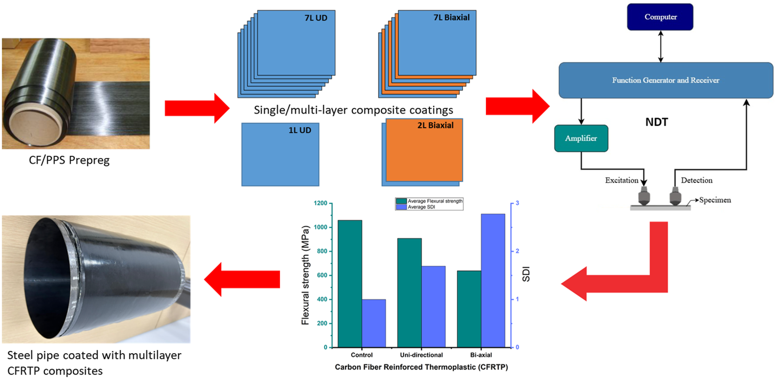
A unidirectional (UD) carbon fiber/polyphenylene sulfide (CF/PPS) thermoplastic prepreg tape (TC1100, sourced from UK, as shown in Figure 1) was used. It contains AS4 carbon fibers at a nominal volume fraction of 60%. The prepreg has an aerial weight of 227 g/m2, yielding a nominal tape thickness of 0.15 mm and a density of 1.6 g/cm. The substrate material consisted of 1 mm thick low-carbon steel plates (Grade DD11, 250 mm × 250 mm), supplied by Ezz Steel (Egypt), representative of pipeline materials. A two-component, room-temperature curing epoxy adhesive, Araldite® 2011 (Huntsman Advanced Materials), was selected for bonding the composite to the steel due to its established high strength and toughness.
34
The adhesive comprises an epoxy resin (Part A) and an amine hardener (Part B), mixed in a 100:80 weight ratio as per manufacturer guidelines. CF/PPS prepreg UD tape, carbon fibers are oriented in 0° direction.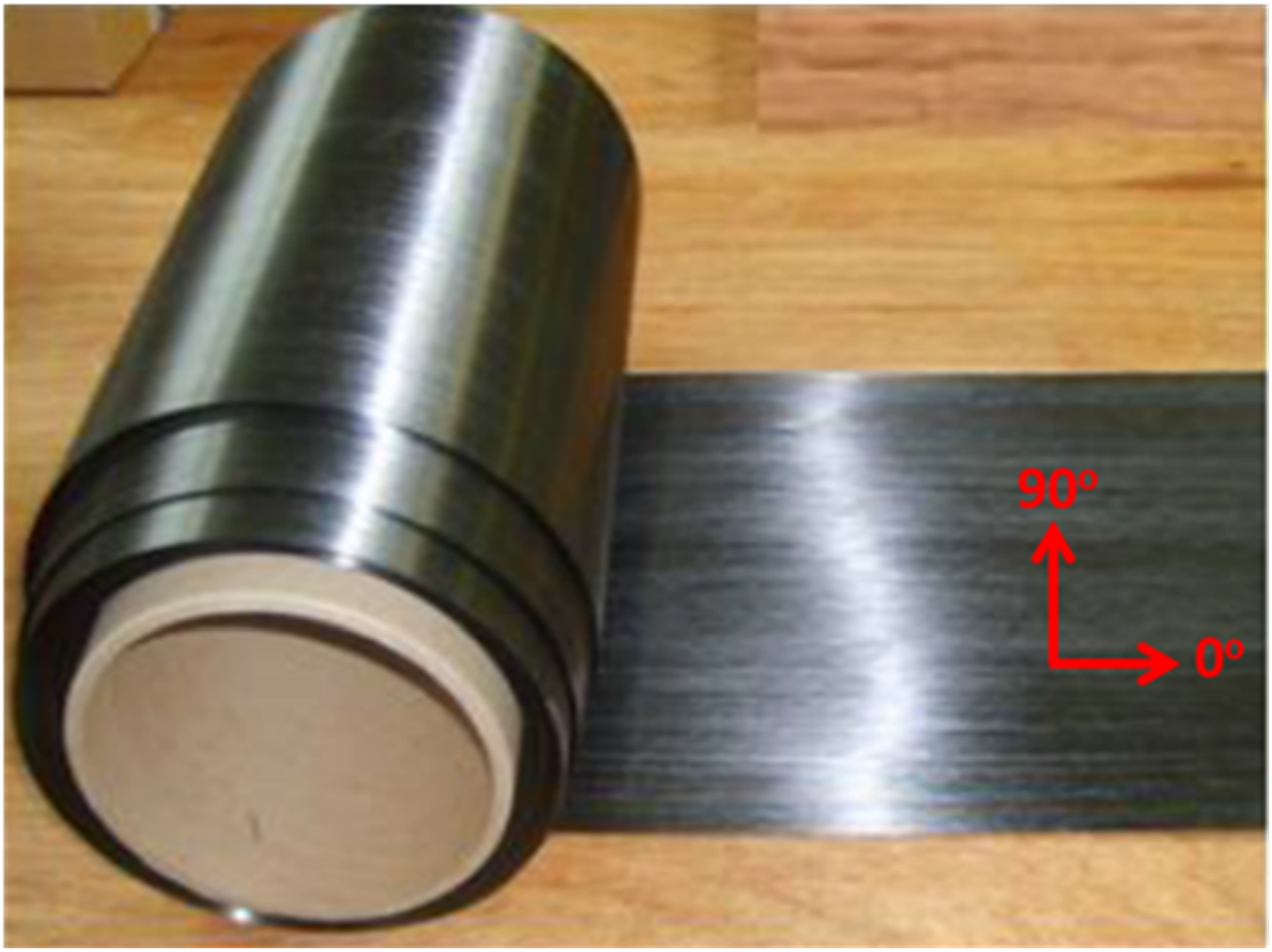
Composite and coated samples fabrication
Four distinct composite configurations were prepared: 1-layer UD, 2-layer Biaxial, 7-layer UD and 7-layer Biaxial. The 7-layer UD composite were fabricated by stacking 7 plies of the CF/PPS prepreg tapes with all fibers aligned in the 0° direction ([0]7). The 7-layer Biaxial sample utilized an alternating [0/90/0/90/0/90/0] layup sequence. For the1-layer UD sample, a single ply was used as received (Figure 1), but in the case of the 2-layer Biaxial specimen, two plies were used, one is laid along 0° direction and the second is oriented at 90°. Multi-layer panels (250 mm × 250 mm) were consolidated using compression molding, involving heating to 300°C under 1 bar pressure for 10 minutes, followed by controlled cooling. 9
Prior to bonding, the steel plate surfaces were grit-blasted to enhance surface roughness and promote mechanical interlocking with the adhesive. 35 Both, the consolidated composite panels and the steel plates were then sectioned into coupons: 125 mm × 20 mm for mechanical and ultrasonic testing, and 20 mm × 20 mm for microscopy. The Araldite® 2011 adhesive was thoroughly mixed and applied as a thin, uniform layer (target thickness 0.05–0.10 mm) to the mating surfaces of the grit-blasted steel and the composite coupons. 35 The components were carefully aligned and assembled, then held under light pressure while the adhesive cured at ambient room temperature for at least 24 hours to ensure full bond strength development. Uncoated steel coupons served as control specimens.
Ultrasonic testing
The experimental setup (Figure 2) for ultrasonic testing employed a high-precision configuration optimized for analyzing composite-coated steel specimens. Central to the system was a pair of Pacific Waves NDT Inc. PW21-S piezoelectric transducers (PZT) operating at a calibrated center frequency of 250 kHz ± 5 kHz, specifically engineered for complex structural inspections. These transducers were arranged in a pitch-catch configuration on the steel substrate surface of 125 mm × 20 mm bonded coupons, maintaining a 100 mm coaxial separation distance while using ultrasonic gel couplant to ensure consistent energy transmission. Experimental set up of nondestructive (Ultrasonic) tool.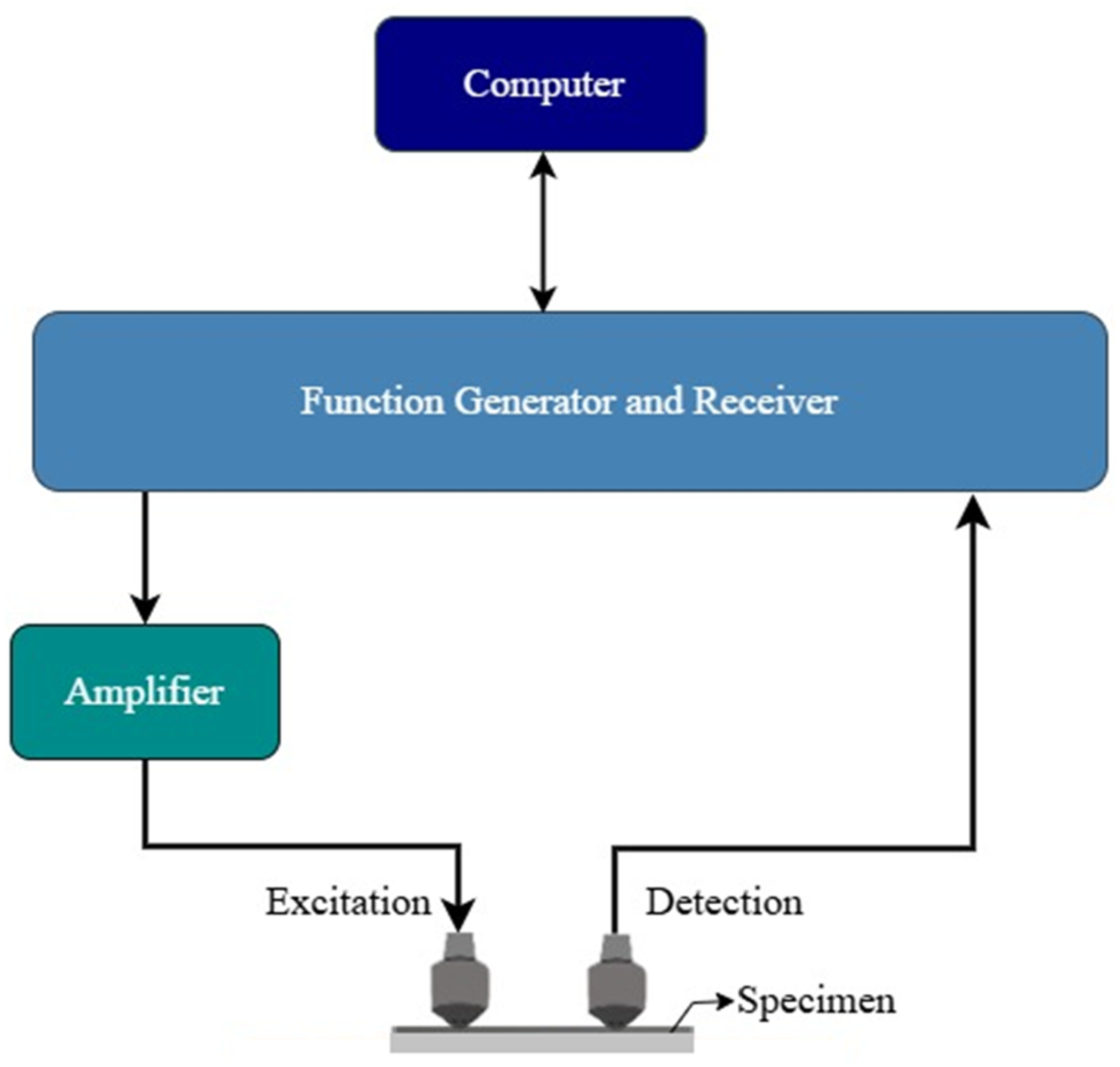
Signal generation and acquisition utilized a computer-controlled workflow featuring a USB function generator, PiezoDrive PD200 high-voltage amplifier, and TiePie HS5 receiver operating at a 50 MHz sampling frequency, enabling high-resolution capture of both linear and nonlinear wave propagation characteristics. The setup’s single-surface accessibility – critical for practical pipeline inspection scenarios where only one side is available – allowed comprehensive evaluation of coating integrity through transmitted waveform analysis. Three average measurements per specimen minimized variability from coupling inconsistencies or alignment issues, particularly crucial for nonlinear parameter assessment sensitive to experimental deviations. An example of transient signal and its Fast Fourier Transform (FFT) is presented in Figure 3. (Left) Transient signal and (right) FFT of propagating wave.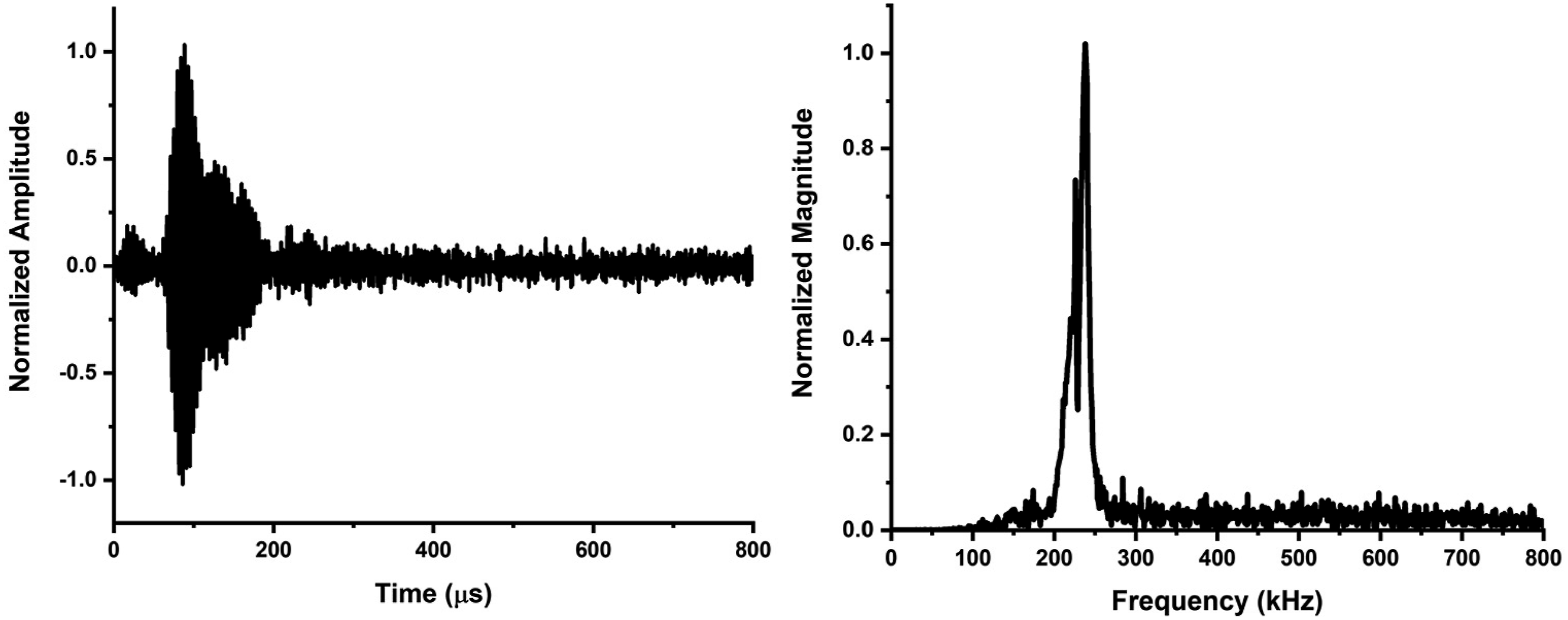
Acquired time-domain signals underwent FFT spectral analysis and S-Transform time-frequency decomposition to extract fundamental frequencies, harmonic components, and time-of-flight (TOF) measurements, forming the basis for calculating hybrid indices (SPC-I and SDI) that quantify coating conditions. This standardized protocol balanced spatial resolution (through 250 kHz optimization) with penetration depth while maintaining signal-to-noise ratios essential for detecting subtle bond-line anomalies. The theoretical foundations of advanced ultrasonic signal analysis techniques employed in this study, including the S-Transform for time-frequency representation and the hybrid ultrasonic indices (SPC-I and SDI) for defect characterization, are comprehensively detailed in the supplementary information (Sections S1.1 and S1.2, respectively). In the following text ultrasonic signal analysis tools are briefly discussed.
S-Transform (ST)
The ST 36 originally developed by Stockwell et al., 37 integrates the temporal localization of the Short-Time Fourier Transform (STFT) with the multiresolution capabilities of the Continuous Wavelet Transform (CWT), while introducing a frequency-adaptive Gaussian window that optimizes time-frequency resolution across spectral components. Unlike traditional Fourier methods constrained by fixed windowing or wavelet transforms limited by scale-dependent mother functions, the ST dynamically adjusts its window width inversely with frequency, enabling precise identification of transient ultrasonic waveform features-such as harmonic distortions and time-of-flight (TOF) variations-critical for detecting subtle bond-line degradation in composite-coated steel specimens. This frequency-dependent resolution, coupled with inherent immunity to cross-term interference common in bilinear transforms, makes the ST particularly suited for analyzing nonlinear acoustic responses captured in the experimental setup’s 50 MHz-sampled signals, where it resolves micron-scale coating defects through enhanced time-frequency localization of modulated signals.
Sideband peak count index (SPC-I)
The SPC-I technique25–28,30 is an advanced hybrid ultrasonic method that leverages both linear and nonlinear acoustic effects to assess material integrity in complex media such as composites. During wave propagation through such materials, nonlinear interactions generate secondary frequency components beyond the fundamental input frequency. These include higher harmonics (integer multiples of the input frequency), subharmonics (half-frequency components), and sideband peaks arising from frequency modulation between interacting wave modes. While higher harmonics and subharmonics emerge from classical nonlinear elastic responses, sidebands specifically originate from the complex interplay of multimodal wave propagation and material heterogeneity. The SPC-I quantifies material heterogeneity or nonlinearity by systematically enumerating these spectral features within defined frequency bands, with particular emphasis on detecting low-amplitude sidebands that serve as sensitive indicators of microstructural changes and damage progression. This method offers higher resolution than traditional nonlinear ultrasonic techniques by using both harmonic and non-harmonic frequency generation. Figure 4 shows the basic operation of SPC-I, which relies on nonlinear modulation. Defects that behave like nonlinear springs such as breathing cracks or clapping interfaces create extra spectral components including sub-harmonics, higher harmonics, and sidebands. The SPC-I algorithm counts how many sideband peaks rise above a continuously updated threshold, giving a direct measure of defect density and nonlinear activity. Schematic representation of the SPC-I, showing the generation of sidebands and harmonics in a defective sample compared to a defect-free baseline.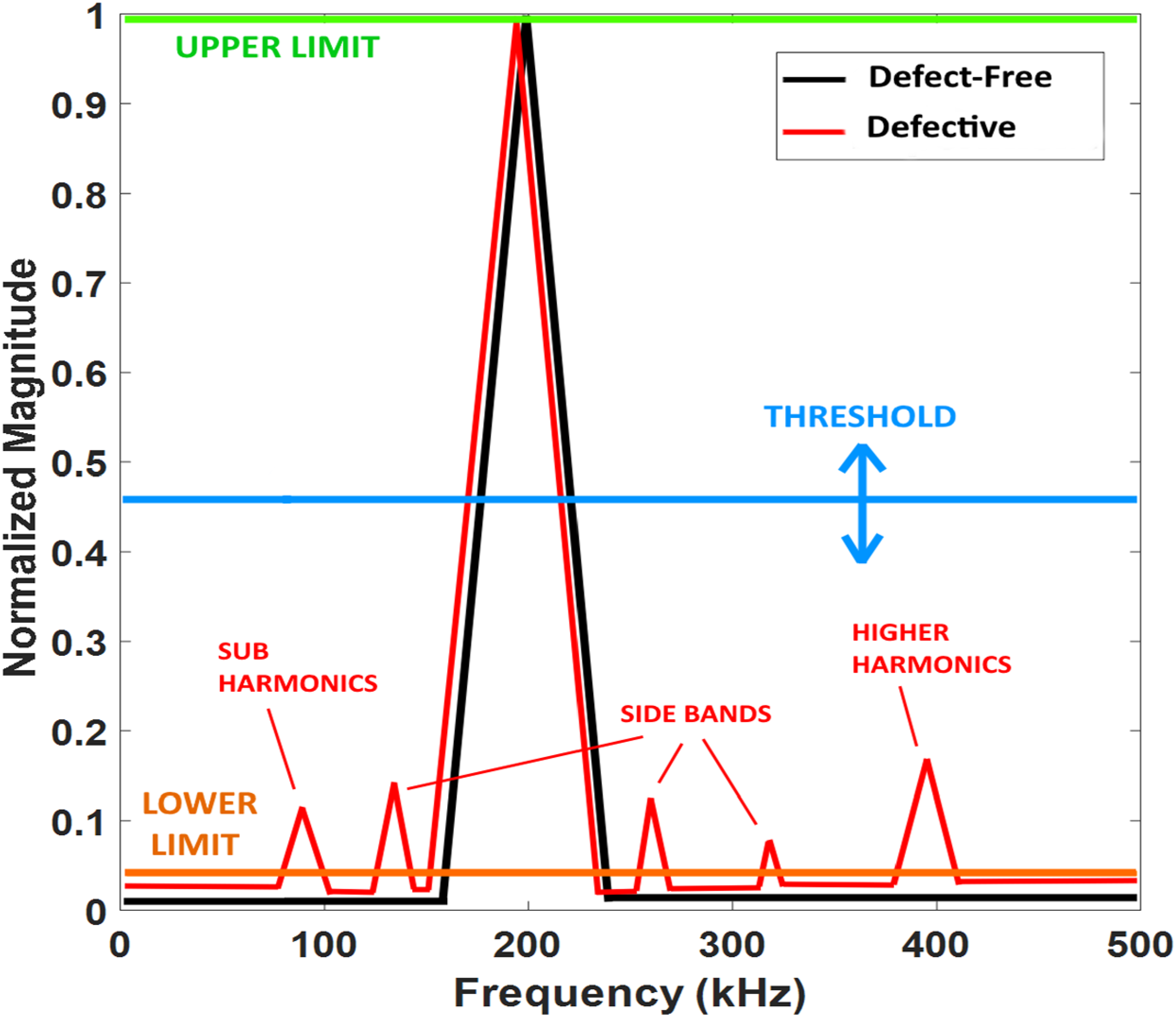
Spectral dissipation index (SDI)
The hybrid SDI
28
technique integrates both linear and nonlinear ultrasonic analysis to enhance damage detection in NDT&E. By combining conventional linear wave propagation with nonlinear phenomena including higher-harmonic generation, breathing cracks, and contact acoustic nonlinearity. This approach achieves superior sensitivity to early-stage microcracks and subtle defects compared to purely linear methods. The SDI framework operates through spectral domain analysis, quantifying energy distribution across harmonic frequencies and modulation sidebands via normalized FFT. This hybrid technique maintains diagnostic accuracy as defects evolve from micro-scale features to macro-scale damage. Its adaptability covers diverse structural configurations in composites, metals, and concrete, enabling precise monitoring of defect initiation and progression through continuous spectral tracking. The SDI’s generalized mathematical formulation supports multiple time-frequency transforms, though FFT remains preferred for its optimal resolution-sensitivity balance in real-time industrial applications. This approach combines linear and nonlinear methods to overcome the limits of each technique while keeping their strengths for defect characterization. Figure 5 shows how SDI works. SDI focuses on spectral broadening. A defect-free sample gives a sharp narrow peak. A defective sample causes energy loss and scattering, which widens the peak. SDI measures this spread compared to the peak’s bandwidth. This gives a clear measure of defect density. Schematic representation of the Spectral SDI, illustrating the spectral broadening and energy dissipation in a defective sample compared to a defect-free baseline.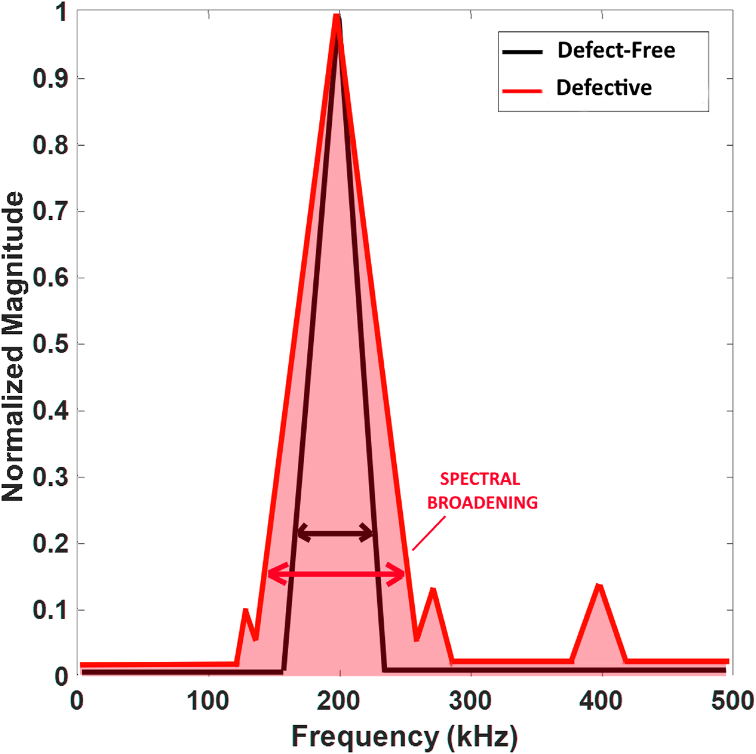
Mechanical testing: Flexural strength
Three-point bending tests were conducted to evaluate the flexural properties of the uncoated steel (control) and the four types of CFRTP coated steel specimens (1-layer UD, 2-layer Biaxial, 7-layer UD, 7-layer Biaxial). Testing followed the guidelines of ASTM D7264/D7264M-07 38 (Procedure A), a standard test method for flexural properties of polymer matrix composite materials. 35 A universal testing machine fitted with a 100 kN load cell was used. Specimens were placed on two supports with a span of 100 mm, and the load was applied at the mid-span by a loading nose at a constant crosshead displacement rate of 1 mm/min. For coated specimens, the composite face was oriented upwards (towards the loading nose), placing it in compression and the steel substrate in tension during the test. Load and displacement data were recorded throughout each test until failure or significant yielding occurred. A minimum of five replicate coupons were tested for each configuration. Flexural strength was calculated from the peak load using the appropriate beam formula for the specimen geometry and loading conditions. The theoretical principles of three-point bending and the complete flexural strength equation with all variable definitions are provided in the supplementary information (Section S1.3).
Optical microscopy
Microstructural characterization39,40 was performed on cross-sections of the four composite-steel bonded specimens to assess composite quality (fiber distribution, void content) and interface integrity (steel-adhesive and adhesive-composite). Samples (20 mm × 20 mm) were sectioned, mounted in a two-part cold-curing epoxy resin within 30 mm diameter molds, and prepared using standard metallographic techniques. The procedure involved sequential grinding with silicon carbide papers (220 grit followed by 1200 grit) and polishing with diamond suspensions (9 μm followed by 3 μm) on appropriate cloths. A final polishing step using a colloidal silica suspension (OP-S) was performed to achieve a high-quality surface finish suitable for microscopic examination. 34 The polished micro sections were then observed using an inverted optical microscope (IM 500, ECHO LAB) equipped with digital imaging capabilities.
Results and discussion
This section presents comparative results from mechanical testing, optical microscopy, and ultrasonic testing and evaluation for the single and multi-layer CFRTP composite coatings on steel substrates, considering both unidirectional (UD) and biaxial ([0/90]) fiber architectures.
The experimental study aimed to develop high-performance composite coating systems capable of withstanding flexural stresses approaching 900 MPa, with particular focus on comparing unidirectional (UD) and biaxial fiber orientations across varying layer counts. Two distinct sample sets were evaluated: a preliminary series with 1-layer UD and 2-layer biaxial configurations, and an optimized series featuring 7-layer UD and 7-layer biaxial architectures. Flexural testing conducted via ASTM D7264-compliant three-point bending methodology revealed critical insights into coating performance. While uncoated steel substrates demonstrated a baseline flexural strength of 1058 MPa (±15 MPa), the 1-layer UD (5.1 ± 0.3 MPa) and 2-layer biaxial (5.3 ± 0.5 MPa) configurations exhibited markedly inferior performance, suggesting minimal structural contribution from thin composite layers. This pattern shifted significantly with the 7-layer systems (Figure 6), where UD-oriented specimens achieved 908 (±18 MPa) MPa flexural strength - meeting the 900 MPa target through enhanced fiber alignment parallel to loading axes. Flexural strength of 7-layer UD and 7-layer Biaxial composite coatings compared to the uncoated steel (control) substrate.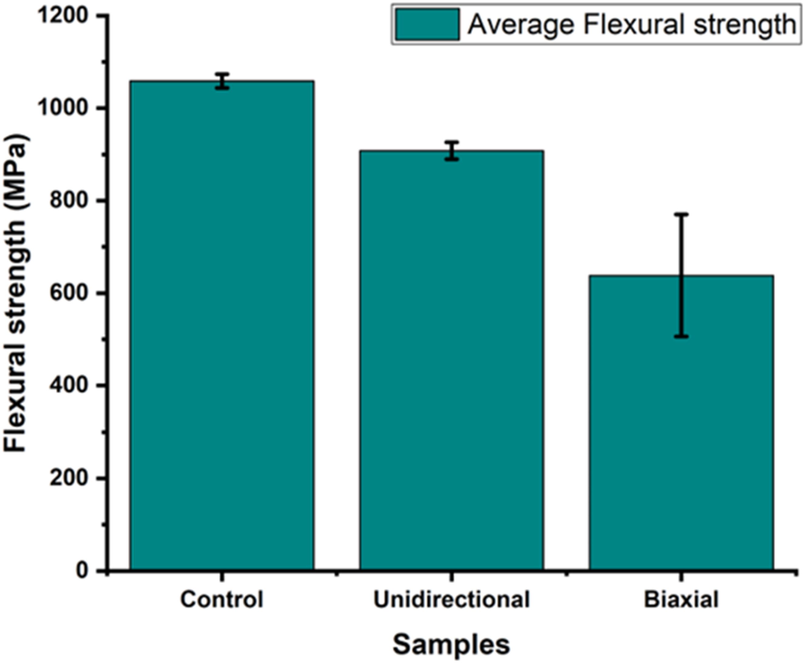
The equivalent 7-layer biaxial configuration underperformed at 638 MPa (±132 MPa), suffering 40% strength reduction versus steel due to interlaminar failure mechanisms. Thus, the 7-layer UD specimen was the only configuration to meet the 900 MPa flexural strength target, whereas the 7-layer [0/90] Biaxial specimen failed to reach this benchmark.
Optical microscopy of the polished cross-sections provides insights into the quality and structure of the thicker, multi-layer composites. Figure 7 presents representative micrographs for the UD and Biaxial configurations. The optical microstructural analysis reveals critical insights into the performance disparities between unidirectional (UD) and biaxial composite coatings observed during flexural testing. Figure 7 demonstrated fundamental architectural differences, with UD specimens exhibiting densely packed 0-oriented fibers (perpendicular to the viewing plane) featuring localized porosity, while biaxial configurations showed alternating 0/90° ply sequences with distinct interlayer interfaces. These structural characteristics directly correlate with mechanical behavior i.e. the UD configurations continuous fiber alignment parallel to loading direction enhance stress transfer efficiency. Whereas, the biaxial system’s orthogonal ply interfaces create inherent weakness planes. Optical micrographs of polished cross-sections of multi-layer CF/PPS composite coatings bonded to steel (steel at bottom, not fully shown). The UD layup (Left), showing predominantly circular fiber cross-sections indicating fibers-oriented perpendicular to the viewing plane (0° direction), along with some visible voids (dark spots). The Biaxial ([0/90]) layup (Right) showing alternating layers of circular (0°) and longitudinal (90°) fiber sections.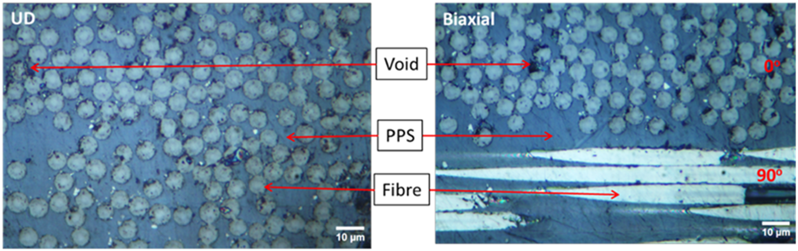
Figure 8 further details interfacial complexity in biaxial systems, revealing three critical boundaries: steel-adhesive (S-A), adhesive-composite (A-C), and composite-composite (C-C) junctions. The C-C interfaces between 0° and 90° plies exhibit discontinuous resin-rich regions and fiber misalignment, predisposing these zones to delamination initiation under bending stresses. Optical micrograph highlighting interfaces in the Biaxial CF/PPS coating. S-A interface shows the grit-blasted steel surface bonded to the adhesive layer. A-C interface shows the relatively smooth bond between the adhesive layer and the first composite ply (0° orientation in this view). C-C interface between subsequent 0° and 90° plies are also visible within the composite coating.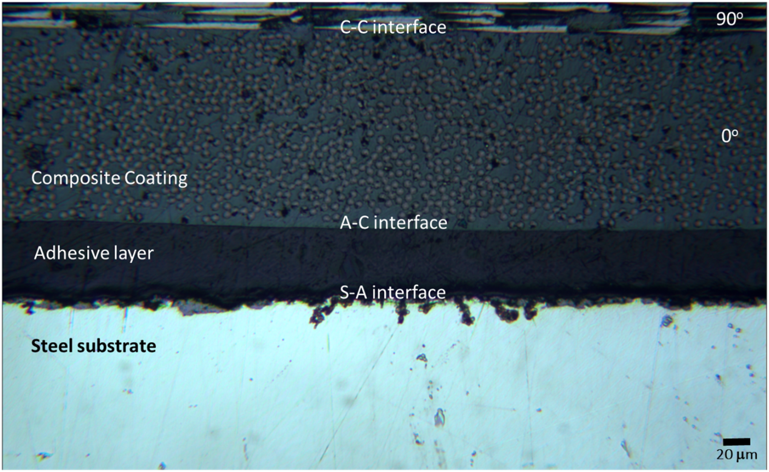
The 7-layer UD coating’s superior flexural strength (908 MPa compared to steel’s 1058 MPa) stemmed from its through-thickness fiber continuity, which redistributed stresses effectively despite a 14% strength reduction relative to the uncoated steel substrate. Conversely, the 7-layer biaxial system’s 40% strength deficit (638 MPa) originated from its laminated structure, where each 0/90° interface acted as a potential crack propagation pathway. This was evidenced by premature interlaminar failure preceding steel yielding.
Microstructural quantification revealed higher void content of 3.67% ± 0.33% in biaxial specimens compared to 3.39% ± 0.34% for the UD ones (Section S1.4 in the supplementary information), concentrated at ply intersections where stress concentrations peaked during bending. This interfacial vulnerability, combined with orthotropic stiffness mismatches between adjacent plies, explained the biaxial system’s reduced performance despite equivalent layer count to UD configurations. The results underscore that achieving the 900 MPa flexural strength target requires both sufficient composite thickness (≥7 plies) and fiber architectures that minimize through-thickness discontinuities.
Preliminary validation tests demonstrated that the hybrid ultrasonic methodology (integrating SPC-I and SDI) can effectively detect material nonlinearity even in very thin composite coatings, whereas conventional nonlinear parameters (e.g., second-harmonic amplitude) were ineffective due to signal attenuation. In subsequent experiments, testing the steel control and composite-coated specimens under a higher excitation level (+50% voltage, V2; see Figure 9) revealed clear distinctions: the composite specimens showed pronounced increases in SPC-I and SDI (Figure 10), whereas the steel exhibited comparatively low-level changes. (Left) Transient signals of 1-layer unidirectional composite sample with respect to varying input voltage and (right) FFT of transient signals. (Left) SPC-I with respect to varying input voltage and (right) SDI with respect to varying input voltage.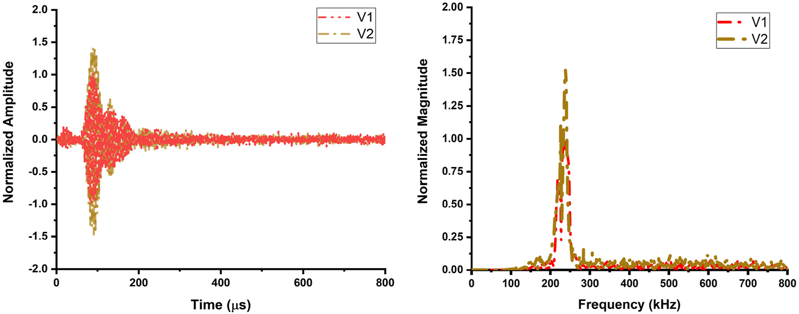
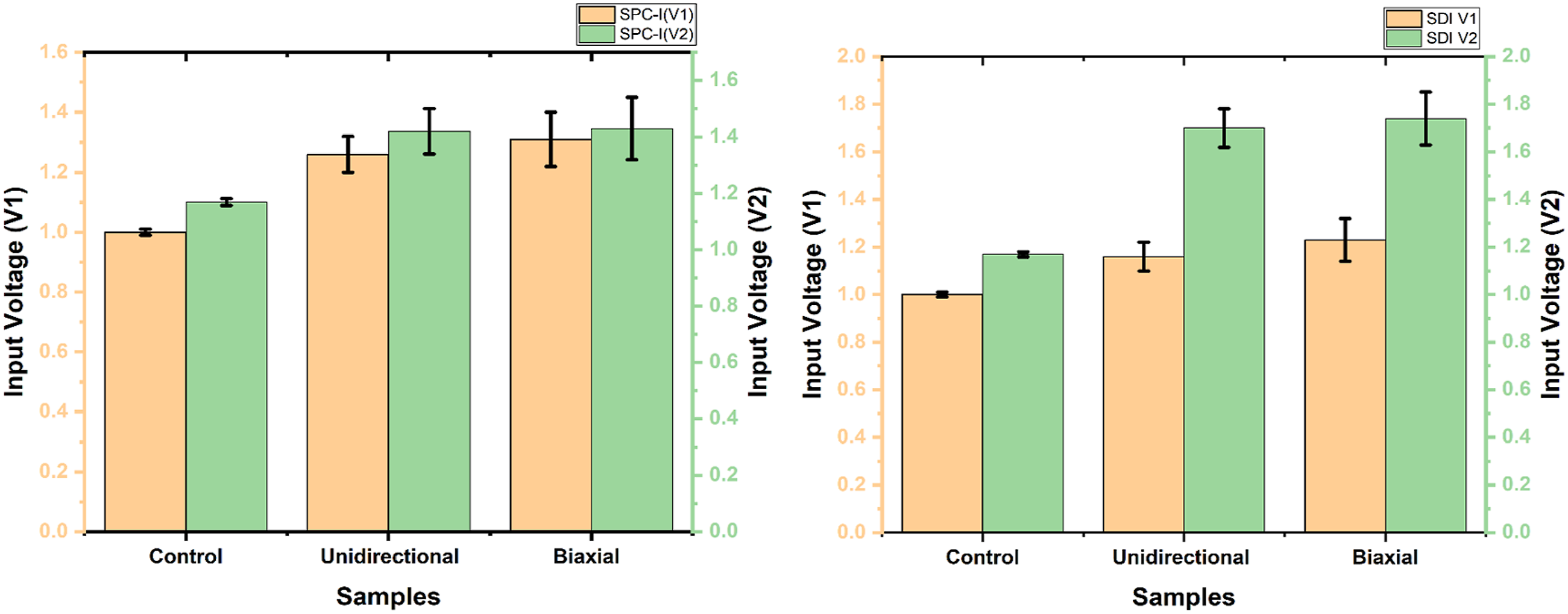
SPC-I and SDI (Figure 10) at V2 (SPC-I: 1.42 ± 0.08 for 1-layer, 1.43 ± 0.11 for 2-layer; SDI: 1.70 ± 0.08, 1.74 ± 0.11), while steel (control) showed only marginal linear increases (SPC-I: 1.17 ± 0.012; SDI: 1.18 ± 0.013). This divergence underscores the method’s ability to detect amplitude-dependent nonlinear mechanisms-such as interfacial microcracking and fiber-matrix friction-activated in composites under higher excitation, phenomena absent in homogeneous steel.
An inverse correlation is observed between the hybrid ultrasonic indices and the specimens’ flexural strength, where steel demonstrated superior mechanical integrity (1058 ± 15 MPa) compared to composites (5.1 ± 0.3 MPa for unidirectional, 5.3 ± 0.5 MPa for biaxial), directly linking microstructural nonlinearity to macroscale mechanical degradation. Voltage-dependent FFT broadening and sideband proliferation confirmed the methodology’s sensitivity to microdefect activation. This finding indicates that greater microstructural nonlinearity (higher SPC-I/SDI) is associated with more severe reduction in mechanical strength. Furthermore, the composite specimens displayed clear nonlinear ultrasonic behavior (sideband generation, spectral broadening) that was absent in the steel control, highlighting the specificity of these hybrid indices for detecting damage in complex, heterogeneous materials.
By resolving subtle energy dissipation (SDI) and wave modulation (SPC-I) in attenuation-prone thin coatings, this dual-index approach overcomes limitations of traditional nonlinear ultrasonics, providing enhanced sensitivity to early-stage damage. The minimal standard deviations across measurements (<11% for composites) and consistent discrimination between specimen types validate the technique’s reliability for in situ structural health monitoring, particularly in scenarios where single-surface access or thin geometries restrict conventional inspection methods.
S-Transform (ST)
The time–frequency analysis reveals distinct ultrasonic signatures for the (uncoated steel) control versus the UD and biaxial composite-coated samples, reflecting their differing structural integrity. The control (steel) shows an initial high-amplitude peak at 0.075 ms and 0.236 MHz (normalized amplitude 1.0) followed by progressively lower peaks at 0.105 ms and 0.190 ms (frequencies 0.24 MHz; amplitudes 0.75 and 0.53) see Figure 11(a), consistent with a homogeneous medium producing regular backwall echoes. In contrast, the UD-coated steel exhibits two nearly equal-amplitude peaks at 0.077 ms and 0.100 ms (both 0.247–0.249 MHz, amplitudes 0.87), with a moderately strong third peak by 0.122 ms (0.239 MHz, 0.61 amplitude) see Figure 11(b). This sustained multi-peak response indicates efficient through-thickness transmission with minimal attenuation, correlating with the UD sample’s high flexural strength (908 MPa) and its cohesive microstructure (fibers aligned parallel to load, minimal delamination). The biaxial [0/90] coating, on the other hand, produces a higher initial peak (1.02 amplitude at 0.0756 ms, 0.254 MHz) but a sharp drop in subsequent peaks (second peak 0.12 ms at 0.251 MHz with only 0.49 amplitude; third at 0.147 ms, 0.228 MHz and 0.39 amplitude) see Figure 11(c). This rapid attenuation and slight downshift in frequency content for later arrivals point to significant internal scattering and energy dissipation in the biaxial laminate, attributable to its orthogonal ply interfaces and voids that act as stress concentration and reflection sites. These ultrasonic characteristics mirror the mechanical performance: the biaxial sample’s weak ultrasonic tail coincides with its lower flexural strength (638 MPa) and observed inter-ply delamination under load, while the UD architecture’s robust ultrasonic signal agrees with its superior load-bearing capacity and intact fiber/matrix interfaces. S-Transform: (a) Control samples, (b) UD samples, (c) Biaxial samples.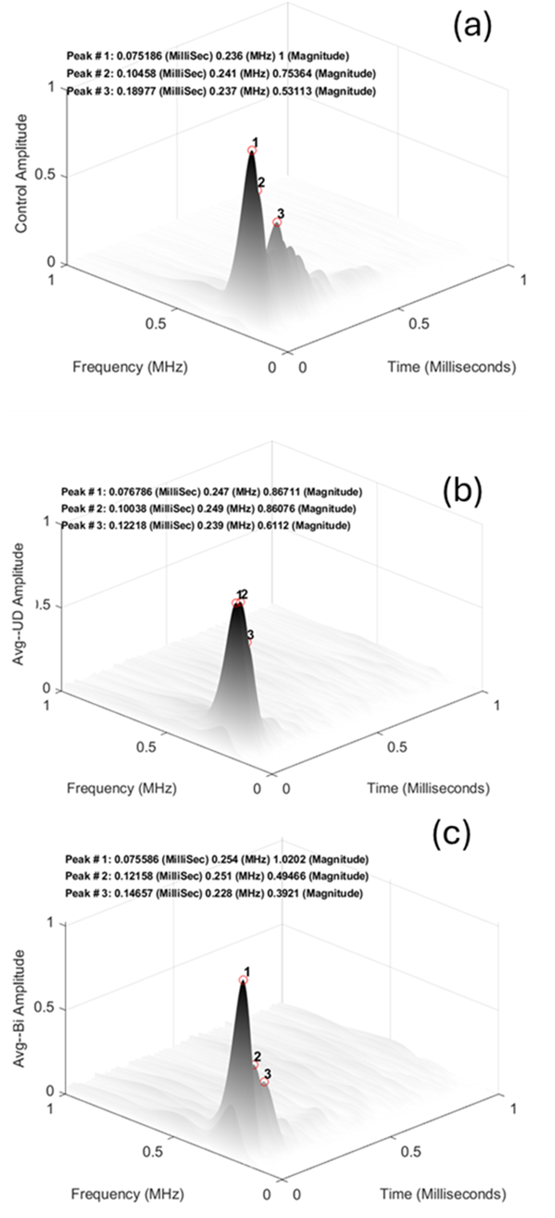
In summary, the S-Transform analysis confirms that material architecture profoundly influences ultrasonic wave propagation – the continuous fiber reinforcement in the UD coating preserves signal magnitude across multiple arrivals (indicating high structural integrity), whereas the multi-directional layered structure in the biaxial coating causes dispersed, attenuated signals beyond the first peak, underscoring how fiber orientation and defects (delamination, void content) degrade both the ultrasonic response and the composite’s mechanical resilience.
Sideband peak count index (SPC-I)
The hybrid ultrasonic SPC-I demonstrated exceptional sensitivity to microstructural heterogeneities in 7-layer composite coatings, correlating strongly with mechanical performance (Figure 12) and optical microscopy findings. The 7-layer unidirectional (UD) specimens exhibited SPC-I values of 1.70 ± 0.21, reflecting their homogeneous fiber architecture characterized by densely packed 0°-oriented fibers (Figure 7). Optical micrographs confirmed minimal void content and continuous fiber alignment parallel to the loading direction, which facilitated efficient stress transfer and contributed to the UD system’s near-target flexural strength of 908 MPa, a 14% reduction compared to uncoated steel (1058 MPa). In contrast, the 7-layer biaxial configuration showed significantly elevated SPC-I values of 2.91 ± 0.51, directly attributable to its alternating 0°/90° ply architecture. These orthogonal interfaces, visible as resin-rich zones with discontinuous fiber alignment (Figure 8), acted as preferential sites for stress-induced microcracking and wave modulation, amplifying nonlinear sideband generation. The inverse relationship between SPC-I and flexural strength, as shown in Figure 12, validated the index’s diagnostic power for interfacial defect quantification. Higher SPC-I values (biaxial: 2.91 ± 0.51) signaled greater microstructural disorder and weaker mechanical integrity compared to UD specimens (SPC-I: 1.70 ± 0.21). Flexural strength versus SPC-I for Control, UD and Biaxial samples.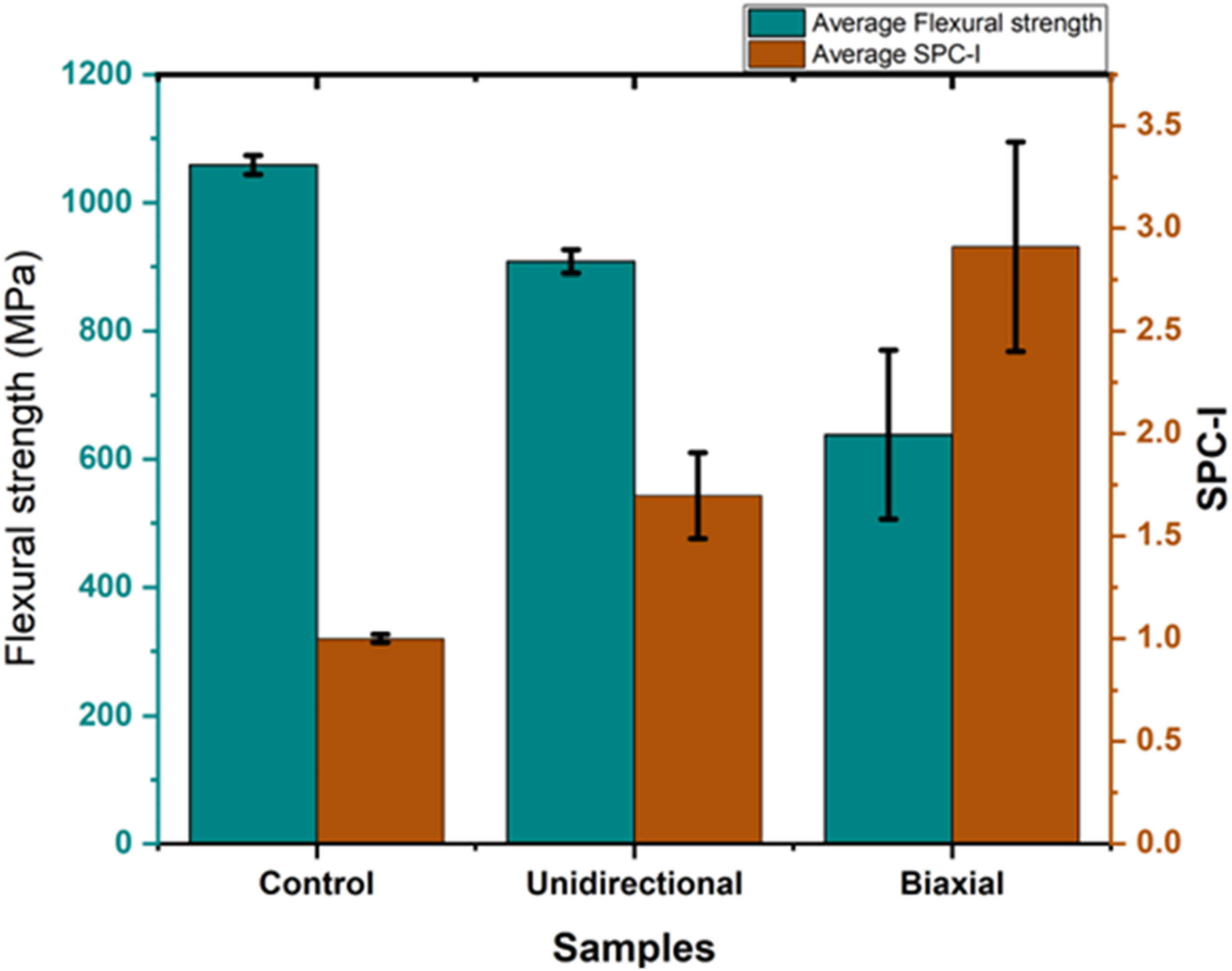
Spectral dissipation index (SDI)
Complementing SPC-I, the SDI framework explains energy dissipation mechanisms governing the 7-layer composite performance. The UD architecture’s continuous fiber alignment minimized interfacial discontinuities, yielding an SDI of 1.94 ± 0.22, consistent with its robust flexural strength (Figure 13). Optical microscopy revealed that UD specimens maintained structural integrity, with stress redistribution enabled by through-thickness fiber continuity. Conversely, the 7-layer biaxial configuration exhibited SDI values of 2.78 ± 0.33, reflecting energy loss through interlaminar slip and microplastic deformation at alternating 0°/90° interfaces. These ply boundaries, quantified as having higher void density than UD specimens, generated localized stress gradients that broadened FFT spectra and enhanced viscous damping. The inverse SDI/flexural strength correlation i.e. 638 MPa for biaxial versus 908 MPa for UD highlights how interfacial complexity governs mechanical degradation. Critically, SDI detected damages in UD specimens despite their near-target performance, demonstrating its utility for identifying subcritical damage in structurally sound coatings. Flexural strength versus SDI for Control, UD and Biaxial samples.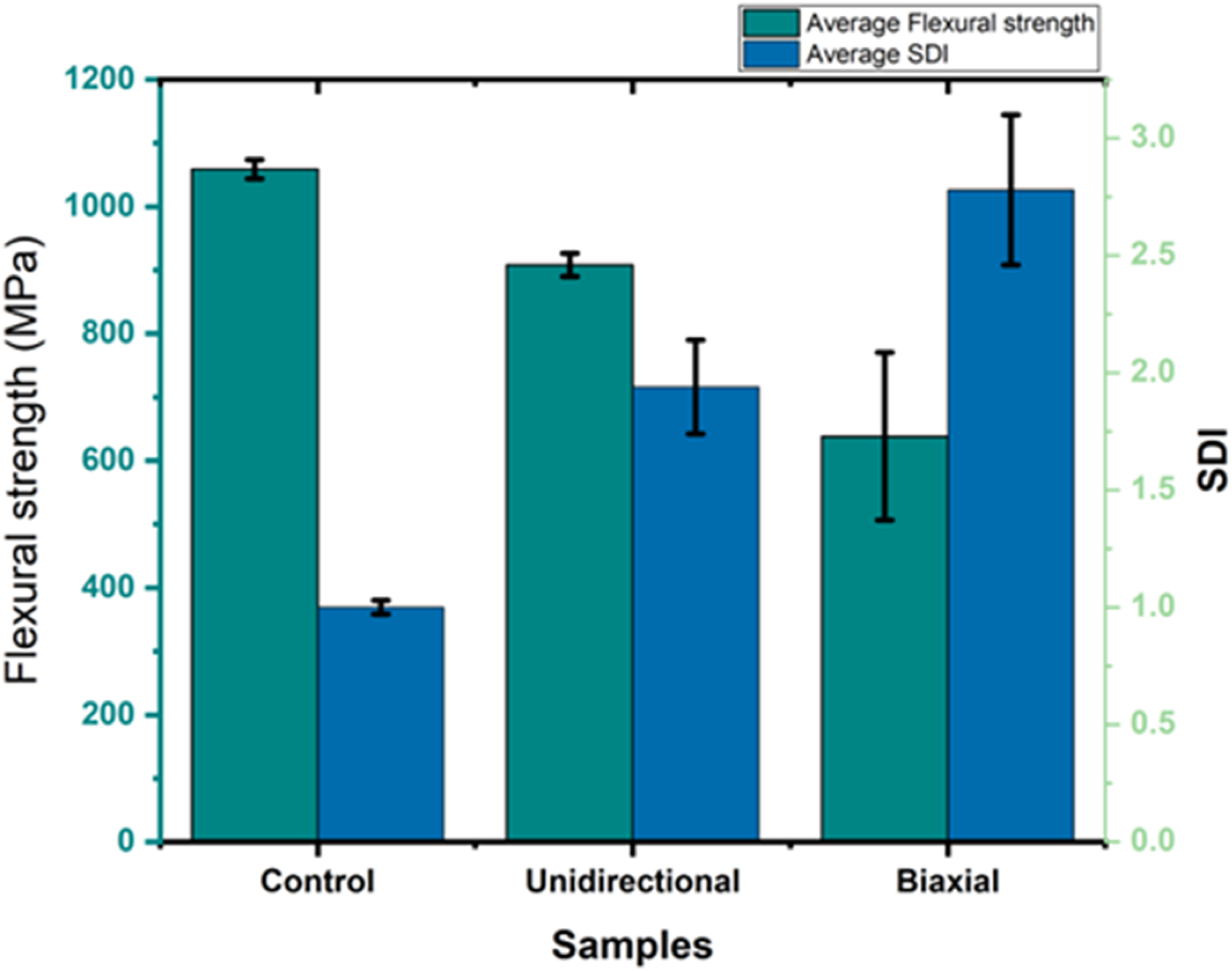
The synergy between SPC-I and SDI provides a comprehensive framework for evaluating 7-layer composite integrity. Biaxial specimens’ elevated indices (SPC-I: 2.91, SDI: 2.78) versus UD (SPC-I:1.70, SDI: 1.94) directly reflect their microstructural vulnerability: each 0°/90° interface introduces 15% additional wave scattering and energy dissipation compared to UD’s continuous fibers. The 7-layer UD’s mechanical superiority emerges from its aligned architecture, which reduces interfacial discontinuities compared to biaxial, minimizing both nonlinear wave interactions and energy loss. This microstructure-driven performance is captured in the hybrid indices’ predictive capacity-SPC-I maps interfacial defect density, while SDI tracks bulk energy dissipation, together enabling multi-scale damage assessment. The methodology’s proven discrimination between failure modes and its correlation with mechanical outcomes validate its adoption for quality control in high-performance coating systems.
To demonstrate the applicability of the developed CFRTP composite coating to real steel pipelines used in the oil and gas industry, small prototype pipe sections were manufactured, as shown in Figure 14. Sheets of low-carbon steel were formed into pipes of different diameters (159.2 mm and 254.65 mm) and coated with single layer and multi-layer (7-layer) CFRTP composites using Araldite adhesive. Two demonstrators: steel pipes coated by single layer of CFRTP composite (Right) and multilayer (7-layer) biaxial composite (Left).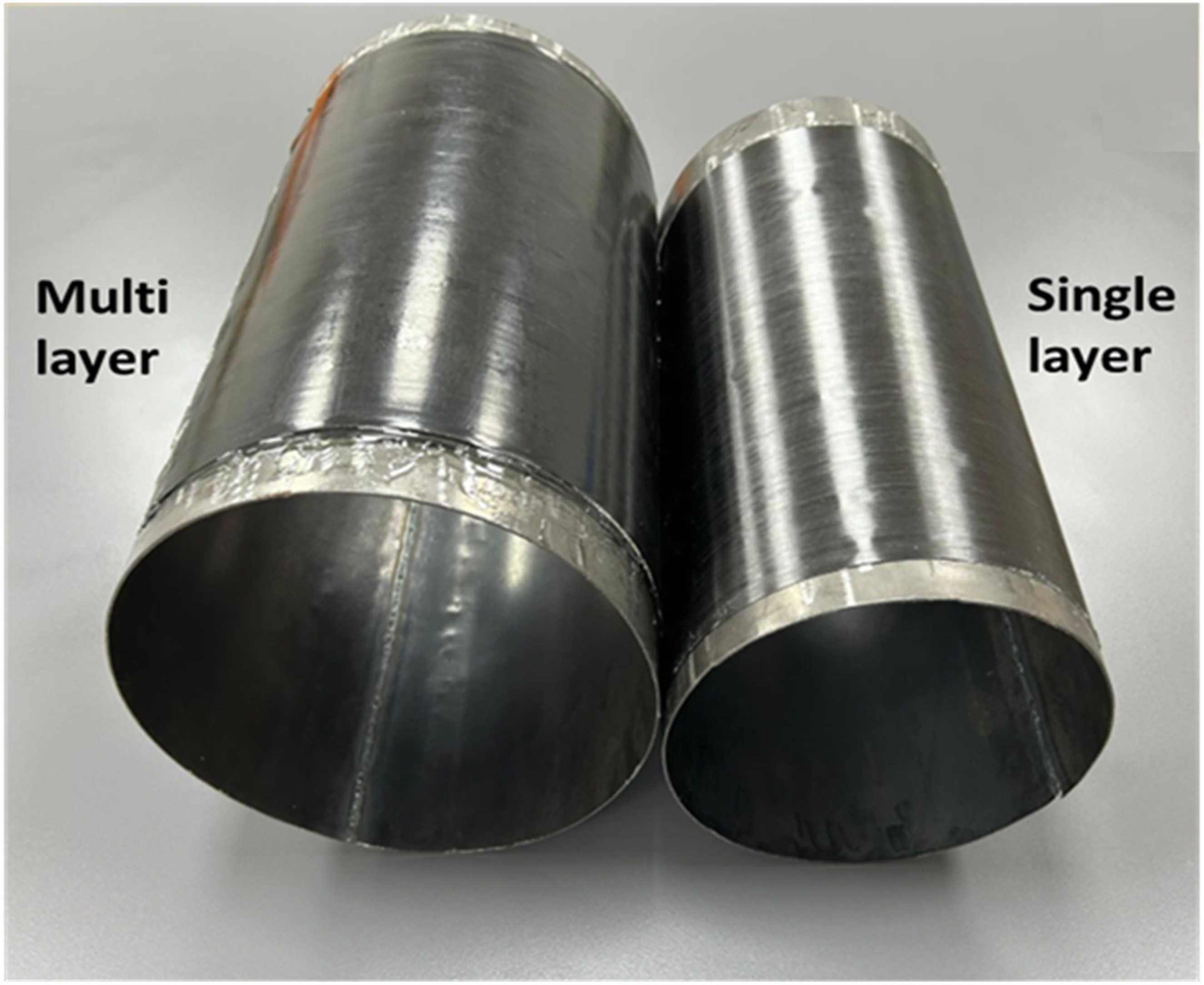
Visual inspection and handling of the coated pipe sections indicated strong adhesion between the composite coating and the steel substrate, suggesting feasibility or pipeline protection applications. The ultrasonic testing methodology developed in this research demonstrates potential as a valuable tool for nondestructive evaluation and quality assessment of advanced composite coating systems. With further development, this approach could be adapted into a portable field inspection tool suitable for oil and gas industry requirements. However, quantitative mechanical and ultrasonic testing of these curved pipe sections is needed to fully validate performance under realistic service conditions.
Conclusion
This study demonstrated the comparative effectiveness of ultrasonic testing integrated with mechanical testing and microscopy for assessing single-layer, double layer, and seven-layer carbon fiber/polyphenylene sulfide (CF/PPS) composite coatings on steel substrates across unidirectional (UD) and biaxial layup configurations.
The hybrid ultrasonic indices (SPC-I and SDI) exhibited substantially greater sensitivity to microstructural anomalies compared to conventional time-frequency analysis. For single and double-layer coatings, SPC-I and SDI reliably detected the composite layer’s presence and distinguished UD from biaxial configurations, capabilities absent in time-frequency analysis or standalone mechanical tests.
In 7-layer systems, the hybrid indices clearly differentiated UD and biaxial configurations. Biaxial samples showed elevated SPC-I (2.91 ± 0.51) and SDI (2.78 ± 0.33) values, correlating with reduced flexural strength (638 ± 132 MPa) and microscopy-verified inter-ply interfacial defects. In contrast, UD specimens displayed moderate changes in hybrid indices (SPC-I: 1.70 ± 0.21, SDI: 1.94 ± 0.22) linked to localized porosity but retained high flexural strength (908 ± 18 MPa) due to continuous fiber load transfer.
The 7-layer UD system’s achievement of 908 MPa flexural strength, meeting the 900 MPa design target, validated its structural reinforcement potential. Simultaneously, the sensitivity of SPC-I and SDI to subcritical damage in UD specimens demonstrated their capacity to identify damage precursors critical for pipeline coating maintenance. These hybrid indices directly mapped interfacial integrity and porosity density to mechanical performance, establishing their utility for nondestructive evaluation of multilayer CFRTP coatings. By integrating hybrid ultrasonics, microstructural analytics, and mechanical validation, this work advances robust quality assessment protocols for energy infrastructure, enabling early defect detection without compromising coating integrity during inspection.
Future work will focus on: (1) validating the ultrasonic methodology on curved pipe geometries under realistic service conditions, (2) investigating the effects of environmental aging (temperature, moisture, chemical exposure) on coating integrity and ultrasonic response, and (3) developing portable ultrasonic inspection tools for field deployment in pipeline applications.
Supplemental material
Supplemental Material - Nondestructive and structural evaluation of steel coated with CFRTP composites for metallic pipeline systems
Supplemental Material for Nondestructive and structural evaluation of steel coated with CFRTP composites for metallic pipeline systems by Umar Amjad, Ahmed I. A. Abd El-Mageed, Hamad N. Alnuaimi, Mohamed M. Desouky, Mamdouh El-Sayed, Tarek Salem, Ahmed Bahgat Radwan, Affaf K. Al-Oufy, Mohammad K. Hassan, Hassan M. El-Dessouky in Journal of Thermoplastic Composite Materials
Footnotes
Author contributions
Declaration of conflicting interests
The authors declared no potential conflicts of interest with respect to the research, authorship, and/or publication of this article.
Funding
The authors disclosed receipt of the following financial support for the research, authorship, and/or publication of this article: This paper is based upon work supported by the Science, Technology & Innovation Funding Authority (STDF) under grant number 46297.
Data Availability Statement
All data generated in this study are already included in this manuscript.
Supplemental material
Supplemental material for this article is available online.
References
Supplementary Material
Please find the following supplemental material available below.
For Open Access articles published under a Creative Commons License, all supplemental material carries the same license as the article it is associated with.
For non-Open Access articles published, all supplemental material carries a non-exclusive license, and permission requests for re-use of supplemental material or any part of supplemental material shall be sent directly to the copyright owner as specified in the copyright notice associated with the article.