
Abstract
This study investigated the impact of CNT film as functional interlayer on the mechanical and electrothermal properties of carbon fiber reinforced polyphenylene sulfide (CF/PPS) composites. Composites with varying interlayer structures were fabricated via vacuum hot-pressing. Microstructural characterization showed that PPS resin fully infiltrated CNT film micropores, forming strong interfacial bonding. The embedded CNT film also enhanced mechanical properties of the composites. Compared to CF/PPS, the tensile, compressive, and flexural strengths of CF/CNTs/PPS composites were enhanced by 6%, 6%, and 10%, respectively, while the interlaminar shear strength remained unaffected. The microscopic orientation of carbon nanotube bundles is characterized by the distribution along the horizontal direction within the plane. Thus, the in-plane oriented CNT film effectively inhibited crack propagation and provided additional load transfer paths during tensile, compressive, and bending deformations, but exhibited limited reinforcement in the through-thickness direction during shear. Additionally, the embedded CNT film endowed the composites with excellent electrothermal performance, including rapid response, uniform in-plane temperature distribution, and long-term stability, with the CNT film structure well preserved after hot-pressing. This study provides a novel approach for fabricating electrothermal-functional thermoplastic composites.
Keywords
Introduction
The rapid development of lightweight aerospace technologies and the integration of new energy vehicle battery modules are driving the increasing demand for high-performance, structurally integrated, multifunctional composites.1–5 In aerospace, the use of lightweight materials is essential to optimize payload capacity, extend flight range, reduce fuel consumption, and enhance overall aircraft performance. Carbon fiber-reinforced thermoplastic composites (CFRTP), known for the high strength, low density, and excellent processability, are gradually replacing traditional thermosetting composites as the core material for next-generation lightweight structures in aerospace.6–8 However, despite their outstanding strength, low density,9–11 and thermal stability, CFRTP still face limitations in electrical conductivity, thermal conductivity, and sensing properties. These shortcomings hinder their ability to meet the growing demand for multifunctional integration in next-generation aerospace systems.12,13 Therefore, enhancing the multifunctionality and structural mechanical properties of CFRTP composites through material design and optimization has become a key area of research in this field.14–19
To address these issues, Numerous researchers in recent years has been to utilize self-supported CNT film as independent functional layers embedded between composite layers.20–22 CNT film is typically prepared by floating catalytic chemical vapor deposition (FCCVD) or array spinning methods.23,24 This film serves as an independent conductive layer, imparting electrothermal, electromagnetic shielding, and other properties to the materials.25–29 It also improves the mechanical performance and thermal stability of the composite, thus enabling the outstanding properties of nanoscale CNTs to be realized at the macroscopic scale.30–33 In thermosetting composites widely used in the aerospace field, CNT film has been shown to significantly enhance both structural and functional properties. Peng Liu et al. 34 explored the effect of CNT film layers on the interlaminar fracture toughness of CF/EP composites. They found that, under mode I fracture, fracture toughness reached its maximum with the addition of two layers of CNT film, and under mode II fracture, fracture toughness gradually increased with the number of CNT film layers, reaching its maximum. Yaofei Huang et al. 35 utilized the FCCVD method to prepare CNT film, which was embedded as a functional layer in glass fiber/epoxy composite structures. This allowed the composite to rapidly heat up, demonstrating its electrothermal deicing function. However, these findings are based on thermosetting resin, and research on CNT film in the thermoplastic composite field remains relatively limited.36,37
Due to the fundamental differences in curing mechanisms, interfacial formation dynamics, and service temperature windows between thermoplastic and thermosetting composites,38,39 the toughening mechanisms and functional effects of CNT film in thermoplastic composites require further evaluation.40,41 Several studies have demonstrated the feasibility of this technology. For example, Díez-Pascual et al. 26 examined the mechanical, electrical conductivity, and thermal conductivity properties of single-wall CNT buckypaper (BP)-reinforced polyphenylene sulfide (PPS) and polyetheretherketone (PEEK) composites. Their results showed significant improvements in stiffness, strength, and thermal conductivity, while ductility and toughness slightly decreased. However, these studies did not systematically investigate the toughening mechanisms of buckypaper in the matrix material or provide long-term performance testing and analysis.
Therefore, this study investigates the effects of CNT film, prepared by floating catalytic chemical vapor deposition, as functional embedding layers on the mechanical and electrothermal properties of CF/PPS thermoplastic composites. Using vacuum molding, four types of composites were prepared: CF/CNTs/PPS, CF/PPS, CF/CNTs, and CF. The effects of CNT film on the mechanical properties of the composites were evaluated through tensile, compression, bending, and shear tests. The interlayer bonding characteristics and fracture mechanisms of CNT film with thermoplastic composites were explored through microscopic morphology characterization of the composite cross-section and fracture surfaces. Electrothermal performance tests were conducted to validate the structural integrity of CNT film within the CF/CNTs/PPS composite and to assess the stability of their electrothermal functionality.
Experimental Methods
Preparation of CNT Film and CF/CNTs/PPS Composites
Carbon fiber/polyphenylene sulfide thermoplastic unidirectional prepreg tape (PPS-CF), CNT film, and PPS film was used in this study. The PPS-CF consists of 52% carbon fiber and 48% polyphenylene sulfide (PPS) resin, with an areal density of 189 g/m2, the unidirectional PPS-CF prepreg, featuring highly aligned carbon fibers for superior mechanical performance, was supplied by Ningbo Zhene Precision Plastics Co., Ltd. The CNTs aerogel was synthesized by cracking carbon source at a high temperature of 1300°C using the FCCVD method. This aerogel was driven out of the reactor by the carrier gas and converted into a ribbon-like shape. Subsequently, the ribbon-like CNTs network was collected by a spindle that moved axially and rotated. The CNT film can be peeled off from the spindle once densified using an ethanol spray solution.
24
The CNT film with a sheet resistance of 0.5 Ω ± 0.05/, a calibrated thickness of 30 ± 3 μm, and an areal density of 14.9 ± 0.5 g/m2 was uesd in this study. The CNT film and its microscopic morphology are shown in Figure 1(a) and (b). The nanoscale CNT bundles are interwoven in the plane, creating voids that facilitate resin penetration during processing. Firstly, a high-energy laser was used to cut the CNT film into 140 mm × 90 mm sheets. Two copper foils, each 300 mm long and 10 mm wide, were used as electrodes. To ensure good contact between the copper foils and the CNT film, conductive silver paint was evenly applied to the junction between the copper foil and the film, ensuring a strong bond on both sides of the CNT film. The CNT film, PPS-CF, and PPS film were then arranged in different stacking structures and placed into a vacuum hot press mold for hot-pressing and melt-formation curing. CNT film: (a) Macro photograph, (b) microstructure.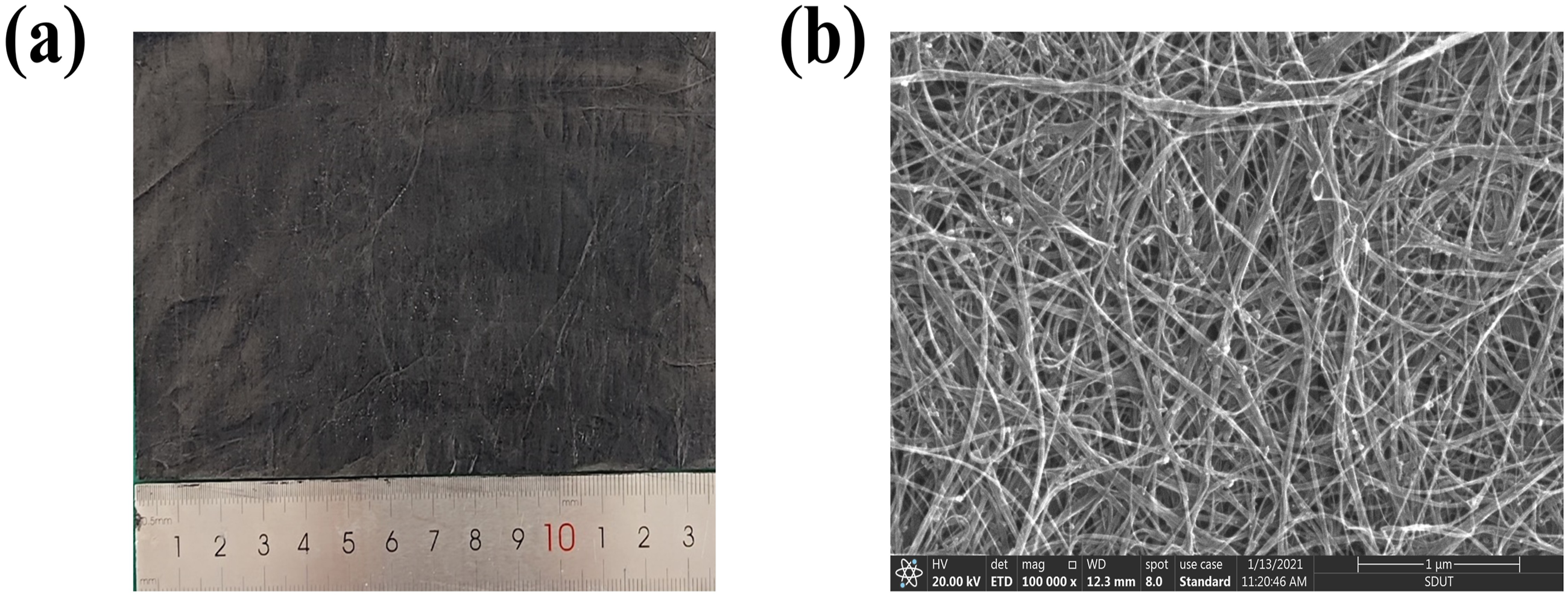
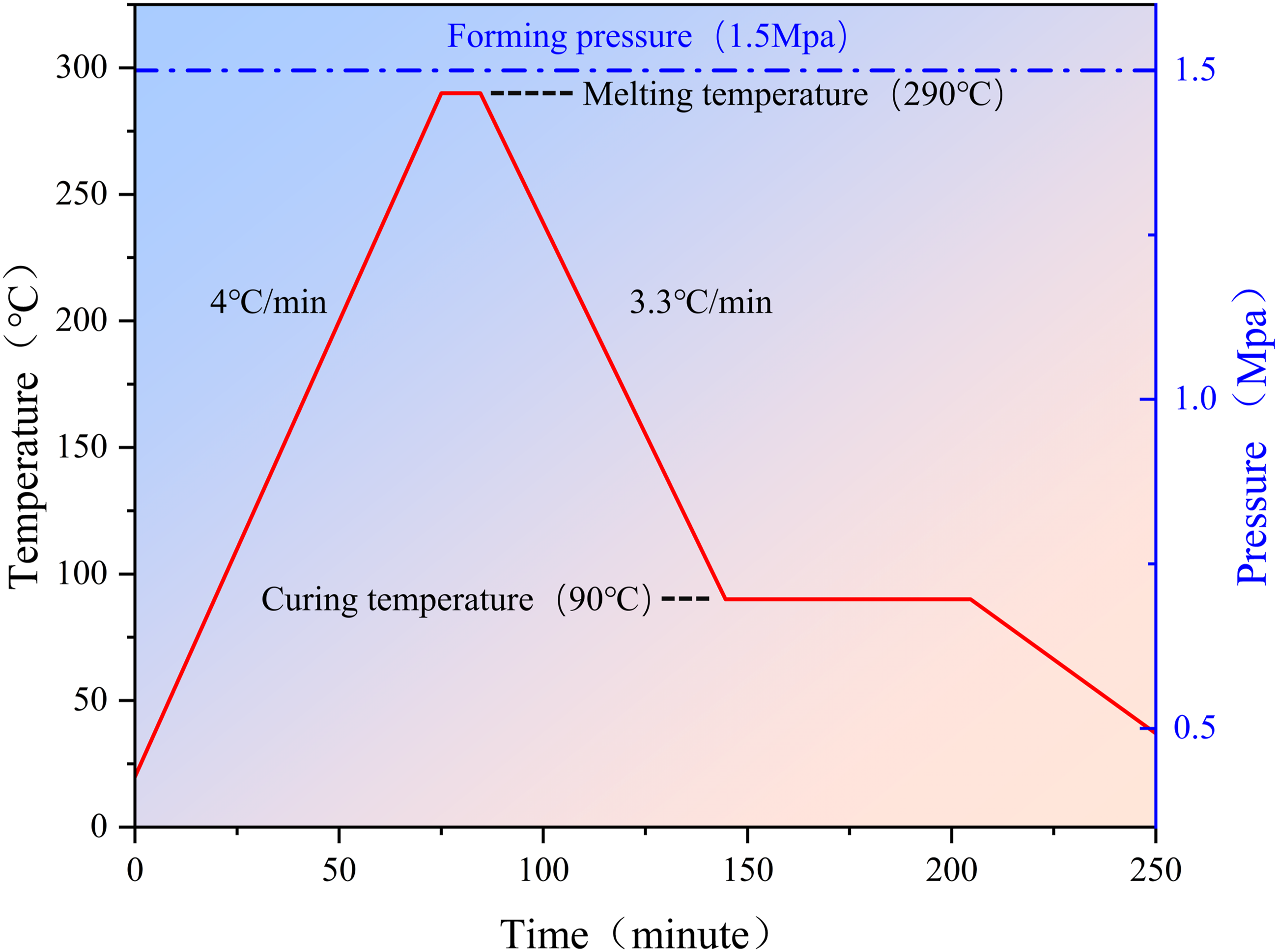
Four different stacking configurations were used to fabricate the composites: CF/CNTs/PPS, CF/PPS, CF/CNTs, and CF, as shown in Figure 2(a). Investigate how different layer combinations affect the composite properties. The stacked materials were then wrapped in PTFE insulation fabric and placed into the mold. The composite fabrication process is illustrated in Figure 2(b). Using a hot-pressing process, as illustrated in Figure 3, the composite plates were completed. The heating rate was set to 4°C/min, and upon reaching 290°C, the temperature was held for 10 minutes. The temperature was then lowered to 90°C, and the material was held for an additional 60 minutes. A pressure of 1.5 MPa was applied throughout the process, along with a vacuum of approximately −0.08 MPa to ensure full resin penetration into the CNT network and to remove any gases and volatiles. Finally, the composite was cooled to room temperature under pressure and then carefully demolded. Composite preparation process and interlayer structure: (a) Interlayer structure of the composite, (b) Schematic of the process flow. Process flowchart.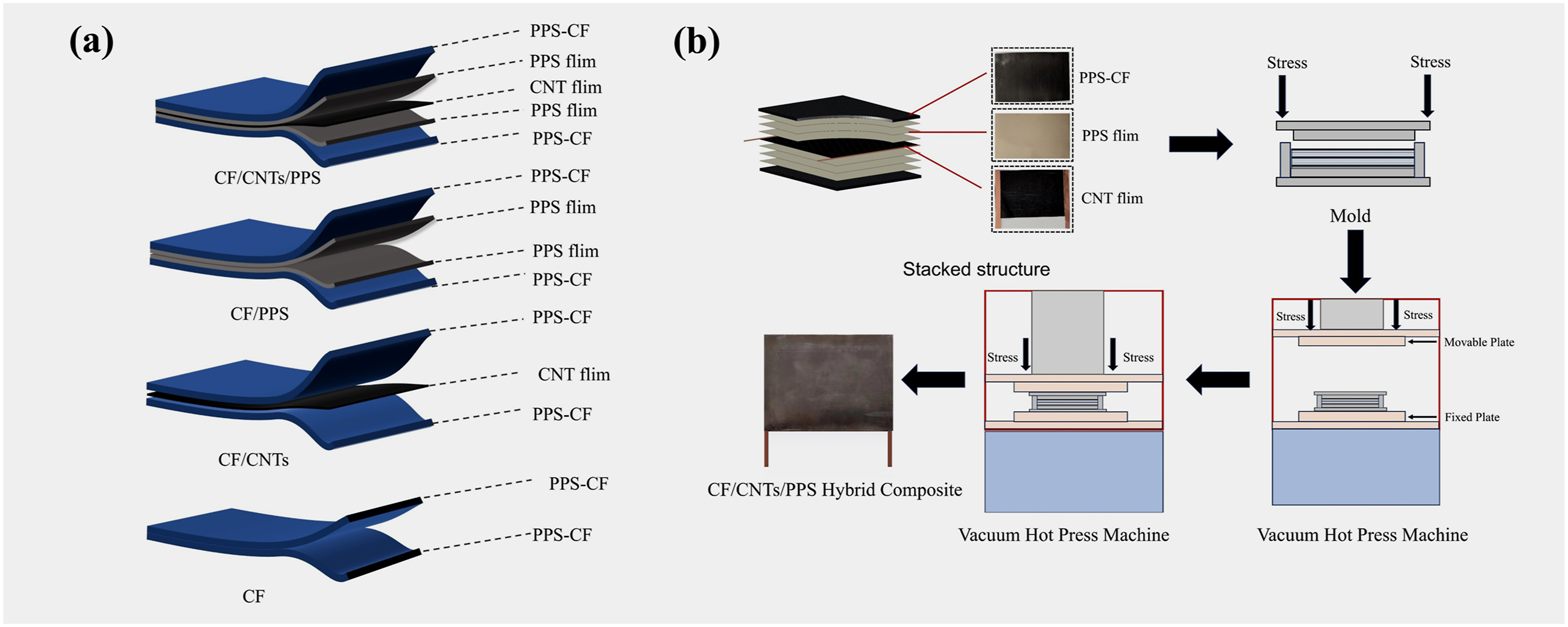
Degree of Crystallinity and Thermal Stability
To evaluate the degree of crystallinity in the composites, we employed dynamic differential scanning calorimetry (DSC). The cured composite samples were cut into 2 mm × 2 mm pieces and placed in an alumina crucible. These samples were then heated in a nitrogen atmosphere at a rate of 15°C/min to 400°C, held at 400°C for 2 minutes, and then cooled to 20°C at a rate of 15°C/min. The DSC test measured the melting enthalpy (ΔH
R
) of the composite materials, while the melting enthalpy (ΔH
O
) for fully crystallized PPS was assumed to be 77.8 J/g. Using equation (1), crystallinity was calculated based on the measured values.

In the equation, α represents the crystallinity of the composite material, and w pps is the mass fraction of PPS in the composite material.
Thermal stability of the composite materials was evaluated using a thermogravimetric analyzer (TG). Cured composite samples, cut into 2 mm × 2 mm pieces, were placed in an alumina crucible. Samples were then heated in a nitrogen atmosphere at a rate of 20°C/min, from room temperature to 800°C. The thermogravimetric curve, showing changes in sample mass with temperature, was recorded to analyze thermal decomposition and stability. Key thermal performance parameters, including the initial decomposition temperature (T 0 ) and the temperature at which the maximum decomposition rate occurs (T max ), were obtained from the TG test, enabling evaluation of the material’s heat resistance in high-temperature environments.
Microstructural Characterization
A Sigma 360 (ZEISS) scanning electron microscope (SEM) was used to observe the microscopic morphology of the cured composite cross-section, interfacial structural features, and fracture morphology after mechanical performance testing. Energy-dispersive X-ray spectroscopy (EDS) was used to characterize the element distribution across the composite cross-section, thus evaluating the degree of impregnation between the PPS resin and CNT film.
Mechanical Property Testing
Mechanical properties of the composite plates were evaluated using an MTS E45 universal testing machine. Uniaxial tension, compression, three-point bending, and short-beam shear tests were conducted according to ASTM D3039, ASTM D6641, ASTM D790, and ASTM D2344, respectively. The tensile specimens measured 80 × 8 mm with a gauge length of 32 mm, while the compression specimens were 80 × 13 mm, with a fixture gap of 5 mm. The bending specimens were 50 × 12.5 mm, with a support span of 40 mm, and the short-beam shear specimens were 40 × 12.1 mm, with a support span of 8 mm. All specimens had a thickness of 0.8 ± 0.1 mm. For the tensile, bending, and short-beam shear tests, the crosshead speed was maintained at 1 mm/min, while the compression tests were conducted at 1.3 mm/min until specimen failure occurred. To ensure the reliability and reproducibility of the results, at least three specimens were tested for each test type.
Electrothermal Performance
To further evaluate the electrothermal performance of the CNT film and composite materials, this study employed a DC power supply (SS-6030KPS) and an infrared thermal imager (FLIR E54) to investigate the electrothermal behavior of the CNT film and CF/CNTs/PPS composites. Initially, the specimens were positioned on mica insulation blocks with low thermal conductivity at both ends, and suspended in air. The ground was lined with aluminum foil to minimize heat loss, and an acrylic cover enclosed the experimental setup to mitigate air convection effects on the results. The dimensions of both the CNT film and CF/CNTs/PPS electrothermal specimens were 140 mm × 90 mm. Temperature changes and distribution were analyzed using the thermal infrared imaging camera. In a room temperature environment (20°C), the temperature responses of the CNT film and CF/CNTs/PPS composite were measured and compared at different voltages. Finally, 100 electrothermal cycles were performed on the CNT film and 1700 cycles on the CF/CNTs/PPS composite using a programmable power supply, further assessing the electrothermal fatigue stability of both materials.
Results and Discussion
Microstructure and Interfacial Thickness of Composites
The cross-sectional structure and interlayer element distribution of the cured composites are shown in Figure 4. A distinct boundary exists between the CNT film and the PPS resin matrix, with the CNT film fully isolated from the carbon fibers by the PPS resin. As seen in the magnified image in Figure 4(a), carbon nanotube bundles are pulled out from the resin and aligned sequentially along the grinding direction of the polished CNT film layer. This indicates that the micro-orientation of the CNT film is aligned with the plane direction of the composite material, with noticeable PPS resin residue on the surface of the CNT bundles. Microstructure and element distribution of composite cross-sections: (a) CF/CNTs/PPS, (b) CF/CNTs, (c-d) EDS surface scanning of CF/CNTs/PPS and CF/CNTs, (e-f) EDS line scanning and interface thickness of CF/CNTs/PPS and CF/CNTs.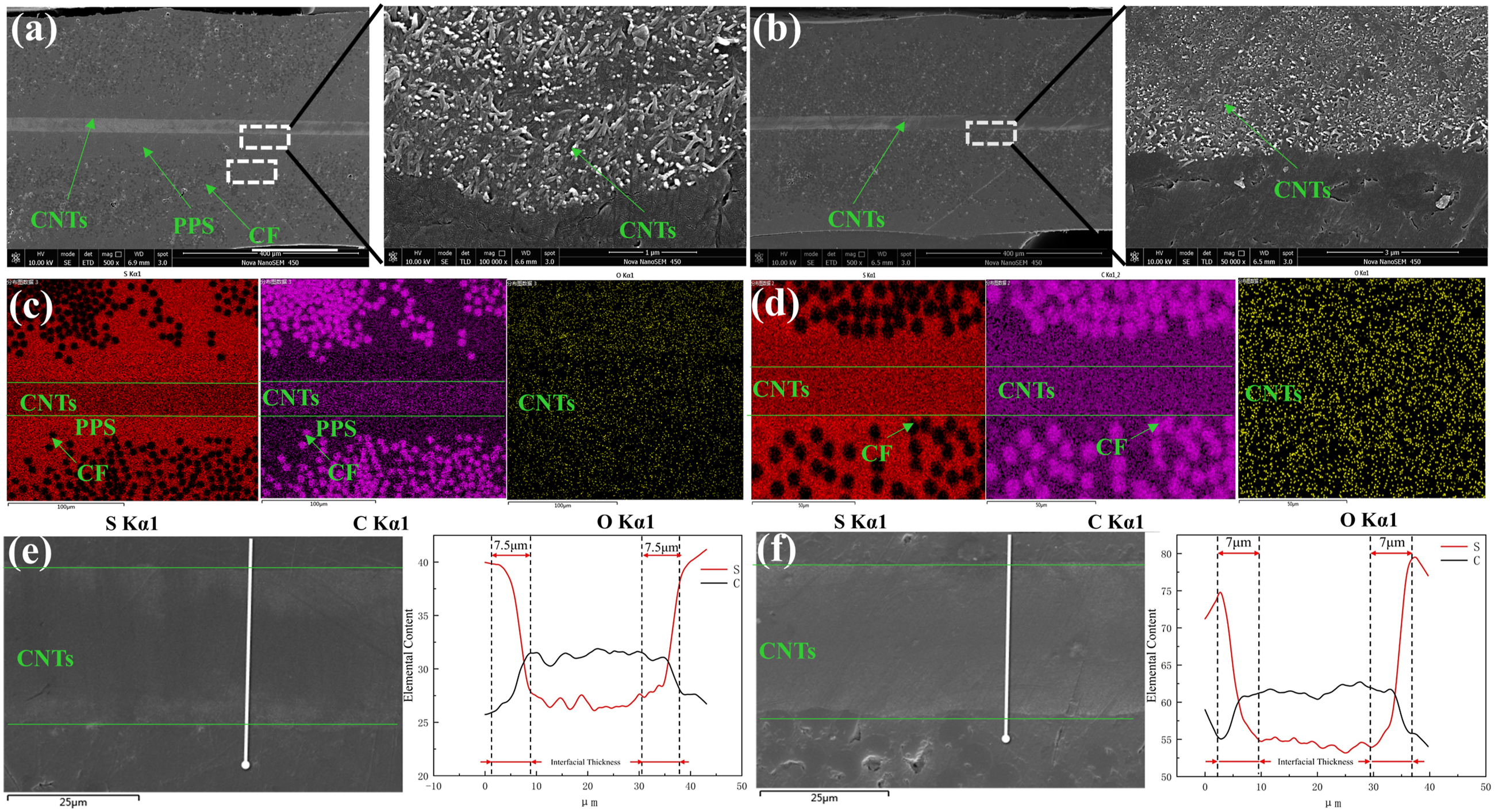
Figure 4(b) shows the CF/CNTs composite with a clear cross-sectional structure and a strong interfacial bond between the PPS resin matrix and the CNT film, with no observable delamination or detachment. The magnified image further reveals that the CNT film is evenly distributed and tightly arranged, with no cracks, pores, or other surface defects.
To analyze the impregnation of PPS resin into the CNT film, energy-dispersive X-ray spectroscopy (EDS) was used to examine the element distribution across the cross-sections of CF/CNTs/PPS and CF/CNTs composites, as shown in Figure 4(c) and (d). The “S” element, characteristic of PPS resin, is uniformly distributed in the CNT film, confirming that PPS resin successfully infiltrates and evenly distributes within the CNT film layer. The “C” and “O” elements are distributed in the CNT film and PPS resin matrix, respectively, with consistent patterns, indicating that the CNT film is continuously and integrally distributed across the composite cross-section. Additionally, the element distribution maps show that in CF/CNTs/PPS composites, the CNT film is isolated from the carbon fibers by the PPS resin. In contrast, in CF/CNTs composites, the CNT film is in direct contact with the carbon fiber bundles, which may cause local short circuits and result in uneven temperature distribution during electrothermal testing, with some areas experiencing excessive temperatures.
To comprehensively evaluate the degree of PPS resin impregnation into the CNT film, EDS line scanning was further used to perform a quantitative analysis of the elemental distribution along the depth direction at the CNT film and PPS resin interface. As shown in Figure 4(e) and (f), a typical element transition zone exists between the CNT film and PPS resin, reflecting the interface layer structure formed as PPS resin gradually infiltrates the CNT film. In the EDS line scan shown in Figure 4(e), it can be clearly observed that the “C’’ element content gradually increases from the outer region, away from the CNT film, towards the area near the CNT film. The “C” content stabilizes in the region close to the CNT film, while the S element content follows the opposite trend, gradually decreasing from the outer region towards the CNT film, and stabilizing after a certain point. This indicates that PPS resin gradually infiltrates from the outside into the CNT film, ultimately resulting in a relatively uniform distribution of PPS resin throughout the CNT film. To quantitatively analyze the thickness of the CNT-PPS interface layer, we selected a scanning path perpendicular to the CNT-PPS interface direction, which passed through both the PPS resin and CNT film. This generated a curve showing the variation in “S” and “C” element content along the scanning path. By analyzing the length of the interval from the initial change phase to the stable phase in the curve for “S” and “C” element content, we defined this interval length as the thickness of the interface layer formed by PPS resin penetration into the CNT film. As shown in Figure 4(e) and (f), the interface layer thickness for CF/CNTs/PPS and CF/CNTs composites was approximately 7.5 μm and 7 μm, respectively. This indicates that the addition of a PPS film between the CNT film and CF/PPS prepreg not only serves to isolate the CNT film from the carbon fibers, preventing direct electrical contact, but also increases the resin content at the interface, which facilitates the penetration of PPS resin into the CNT film. This leads to an increase in the interface thickness, improving the interfacial bond strength.
Crystallinity and Thermal Stability of Composites
DSC analysis results are shown in Figure 5(a). The cured CF/CNTs/PPS composite has a melting enthalpy of 26.28 J/g, with the PPS resin mass fraction at 68%. Crystallinity, calculated using equation (1), is 49.67%. In comparison, the uncured carbon fiber prepreg shows a melting enthalpy of 20.82 J/g and crystallinity of 55%. The decrease in crystallinity is primarily due to the confinement effect of the CNT film on the motion and crystalline growth of the PPS chain segments. The graphitized surface of CNTs provides heterogeneous nucleation sites for the aromatic PPS. More importantly, chain movement at the CNT-PPS interface is significantly restricted, limiting crystal growth and perfection.42,43 This macroscopic effect leads to a decrease in overall crystallinity.
44
Although crystallinity decreased by approximately 6%–7% after curing, it still falls within the performance range required for thermoplastic composites (40%–55%), thus meeting the requirements for practical applications. Crystallinity and thermal stability analysis of composites: (a) DSC heat flow curves: PPS-CF, CF/CNTs/PPS, (b) Thermogravimetric analysis curves: PPS-CF, PPS, CF/CNTs/PPS.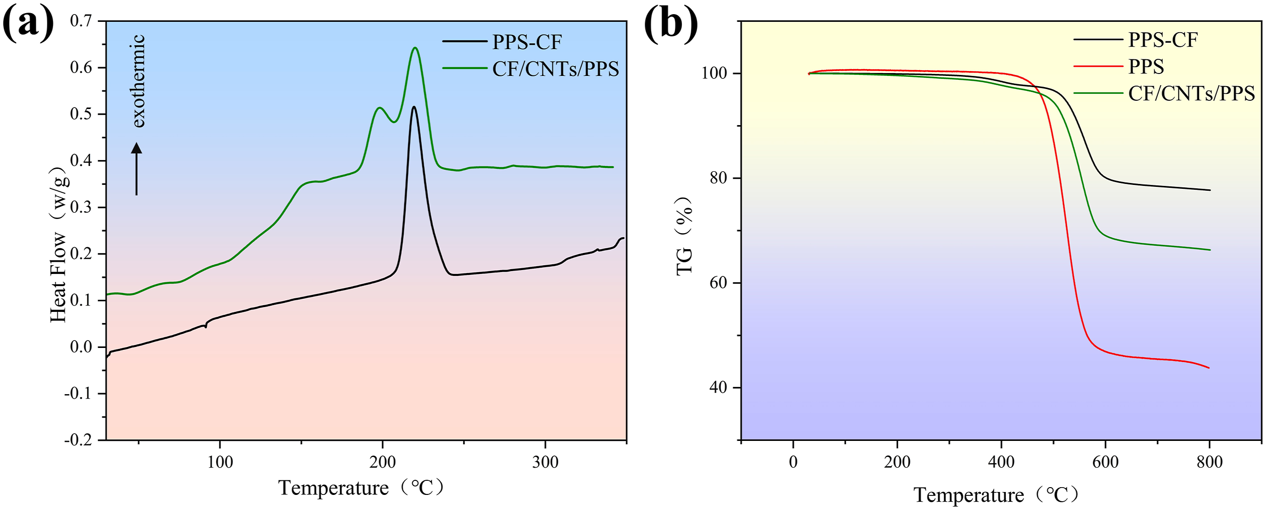
As shown in Figure 5(b), thermogravimetric analysis further illustrates the evolution of the thermal stability of the composites. Pure PPS exhibits a significant mass loss around 500°C, while the mass change of the carbon fiber prepreg and CF/CNTs/PPS composite occurs more gradually and is delayed. Notably, the maximum mass loss temperature of the CF/CNTs/PPS composite is increased to approximately 580°C, indicating that the incorporation of the CNT film significantly enhances the thermal stability of the CF/PPS thermoplastic composite. This improvement provides crucial performance support for its use in composite materials, particularly in high-temperature resistance applications.
Mechanical Properties of Composites
The stress-strain curves for room temperature tensile, compression, bending, and shear tests of composites with different interlayer structures are shown in Figure 6. The addition of CNT film significantly affects the mechanical properties of CF/PPS composites. In terms of tensile properties, the tensile strengths of CF/CNTs/PPS and CF/CNTs reached 974 MPa and 1548 MPa, respectively, representing improvements of 6% and 21% compared to CF/PPS and CF. As shown in Figure 6(a), the stress-strain curve of the composite without CNT film exhibits a sudden stress drop during the elastic deformation stage, indicating internal porosity damage. However, the addition of CNT film may have suppressed the early onset of porosity damage inside the composite. Similar phenomena have been observed in composites with vertically aligned CNT film produced using array methods.
45
Due to CNT film suppression of initial damage, the tensile strength of the composites with embedded CNT film was significantly improved. Stress-strain curves and comparison of mechanical properties of composites: (a) Tensile performance, (b) Compression performance, (c) bending performance, (d) Shear performance.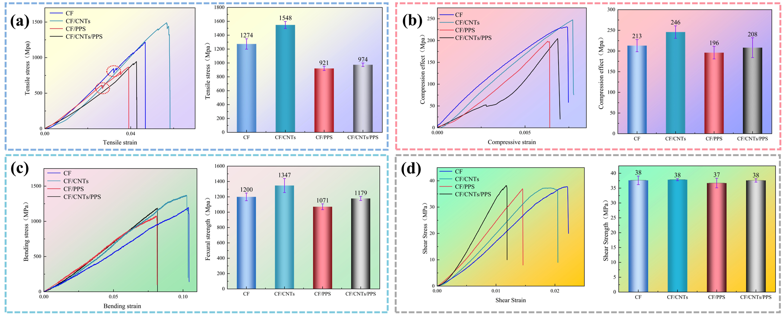
In terms of compression and bending properties, the compression strengths of CF/CNTs/PPS and CF/CNTs were 208 MPa and 246 MPa, respectively, and the bending strengths were 1179 MPa and 1347 MPa. Compared to CF/PPS and CF, the compression strength of CF/CNTs/PPS increased by 6% and 15%, respectively, while the bending strength increased by 10% and 12%. The stress-strain curves show that the addition of CNT film improved both the stress-bearing and deformation capabilities of the material. However, the CF/CNTs/PPS composite exhibits a noticeable stress drop at the early stage of compression, as shown in Figure 6(b). This is due to damage in some microstructures during compression, causing a temporary decrease in stress. The curve then recovers and eventually reaches its maximum value.
In terms of shear properties, the shear strengths of CF/CNTs/PPS and CF/CNTs were 37 MPa and 38 MPa, respectively. The embedding of CNT film did not significantly affect the shear strength of the composites compared to CF/PPS and CF. However, as shown in Figure 6(d), the CNT film significantly increased the shear modulus of the composites. The shear modulus of CF/CNTs/PPS and CF/CNTs were increased from 2.43 GPa to 1.79 GPa to 3.16 GPa and 2.05 GPa, respectively, compared to CF/PPS and CF. As noted in the study by Xukang Wang et al., 46 the introduction of CNT-modified PEEK film in CF/PEEK laminates significantly improved interlaminar toughness, while the interlaminar shear strength remained unchanged, which is consistent with the findings in this study. Additionally, the inclusion of PPS film greatly increased the shear modulus of the composites. This indicates that the material experiences less deformation under shear loads, contributing to improved overall structural stiffness, reduced deformation during service, and enhanced structural stability.
Furthermore, the incorporation of additional PPS film in the CF/CNTs/PPS laminates increases the matrix resin proportion while reducing the overall carbon fiber volume fraction, thereby slightly compromising the load-bearing framework and resulting in a modest decline in global mechanical properties. Nevertheless, the augmented resin content thickens the interlaminar region, facilitating deeper melt impregnation into the porous CNT film network and thereby enhancing interfacial stiffness and load transfer efficiency. Although this approach sacrifices some mechanical benefits afforded by higher fiber content, the PPS film effectively insulates direct conductive contact between carbon fibers and the CNT film, substantially mitigating the risk of short-circuiting due to percolating conductive pathways during electrothermal curing and in-service operation.
Overall, the addition of CNT film significantly improved the tensile, compression, and bending properties of CF/PPS composites, while also increasing the shear modulus without reducing shear strength. It can be concluded that the rational design of the interlayer structure between the CNT film functional layer and the thermoplastic matrix not only enables multidimensional reinforcement of the composites but also offers a new approach for structural optimization, balancing both mechanical performance and electrothermal functionality.
Fracture Characterization of Composites
Fracture morphology of composites with different interlayer structures after mechanical testing is shown in Figure 7. As seen in Figure 7(a) and (b), the CF/CNTs/PPS composite displayed no necking or fiber extension marks during tensile testing. The fracture surface was smooth, with significant resin remaining on the fiber surface and no noticeable fiber pull-out or exposure. Failure occurred uniformly, with the CNT film dissipating energy and suppressing crack growth through mechanisms such as CNT bundle pull-out, fracture, and the tough tearing of the film. In contrast, the CF/PPS composite, lacking CNT film, showed noticeable fiber pull-out and delamination, with exposed fiber ends and uneven tearing. Crack propagation followed a straight line, indicating insufficient overall toughness during tensile testing. Fracture morphology of composites: (a) CF/CNTs/PPS tensile, (b) CF/PPS tensile, (c) CF/CNTs/PPS compression, (d) CF/PPS compression.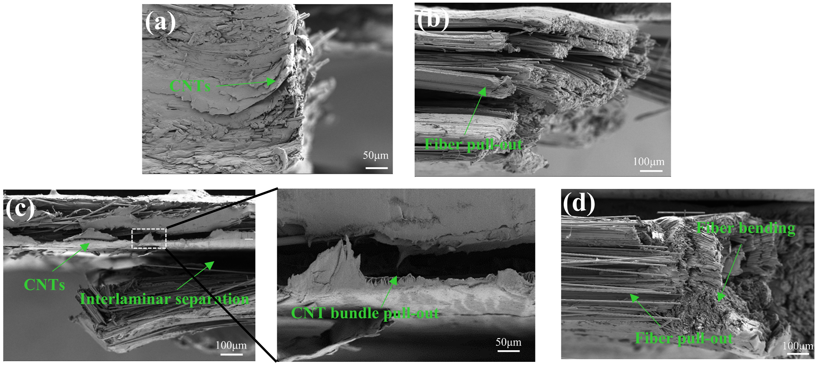
Figure 7(c) and (d) show the fracture morphology after compression. The fracture cross-section of the composite with embedded CNT film exhibited significant interlayer separation and matrix cracking. Some degree of delamination occurred between layers, and the cracks propagated along the interlayers, showing a complex, multi-branch crack structure. A magnified view of the image further indicates that interlayer separation is the primary failure mode. Along the crack propagation path, the separation between CNT bundles and the PPS resin matrix delayed crack propagation, consuming more energy during crack growth. This is reflected in the compression stress-strain curve. In the early stages of compression, when cracks form between the CNT film and the PPS resin matrix, CNT bundles are gradually pulled out from the matrix. This progressive process increases the overall toughness of the composite, leading to a lower compression modulus. However, in the later stages of deformation, the crack propagation rate increased, and the compression stress rapidly rose. Similar toughening mechanisms were observed in the study by Zhouyi Li et al., 47 which demonstrated that CNTs significantly improve interlaminar toughness and enhance the compressive performance of composites by dissipating energy during crack propagation. In contrast, the composite without CNT film showed significant fiber compression and bending after compression fracture, as shown in Figure 7(d). The fibers were clearly exposed, and extensive resin fragmentation occurred, exhibiting typical brittle failure characteristics such as fiber buckling, resin fragmentation, and fiber pull-out.
In terms of bending fracture morphology, as shown in Figure 8(a) and (b), the interlayer structure of the composite with embedded CNT film remains generally intact. Cracks primarily propagate along the interface between the CNT film and the resin matrix, exhibiting distinct interlayer delamination, while fiber pull-out and matrix failure are less pronounced. However, noticeable cracks appear in localized regions. A magnified view of these areas clearly shows crack initiation and propagation at the CNT film interface, with the overall fracture following a typical delamination failure mode. In contrast, the composite without embedded CNT film exhibited a failure mode characterized by fiber pull-out, fiber fracture, and matrix fragmentation during bending. The magnified view of the localized region shows clear sliding misalignment and fracture between the fiber bundles and the resin matrix. This microscopic interfacial damage can easily propagate, leading to overall structural instability under bending loads and ultimately resulting in material fracture. Fracture morphology of composites: (a) CF/CNTs flexural, (b) CF flexural, (c) CF/CNTs shear, (d) CF shear.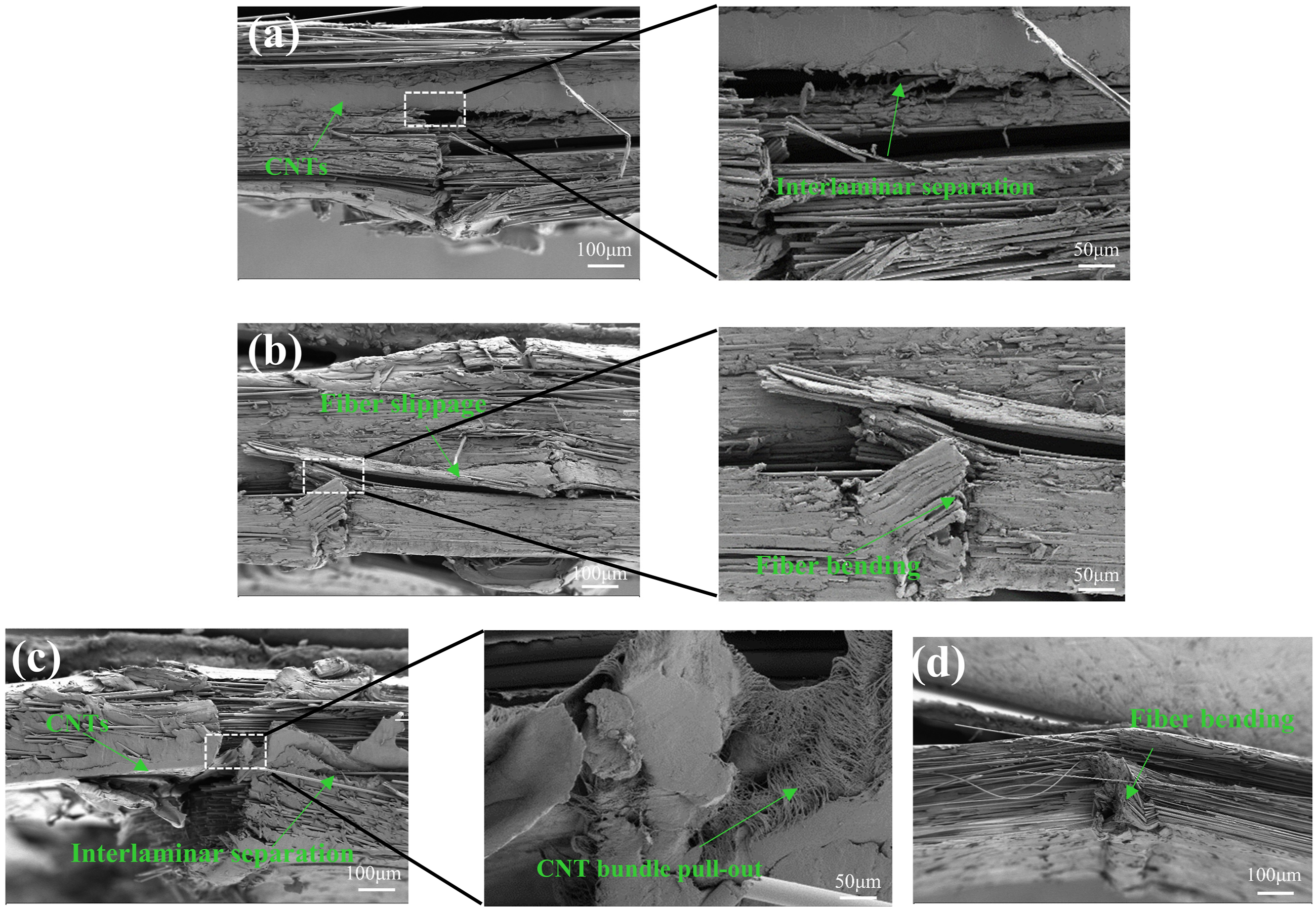
However, under shear load, as shown in Figure 8(c)–(d), stress concentration typically occurs at the interlayer interface of the composites. The fracture of the composite with embedded CNT film shows distinct resin-layered tearing and interlayer separation. The crack path is more regular, and due to local stress concentration, shear cracks propagate more rapidly at the CNT film interface. Additionally, the micro-orientation of the CNT film is primarily in the in-plane direction, with CNT bundles aligned along the plane of the composite material. The in-plane orientation of the CNT film is arranged primarily in the interlayer. 24 In tensile, compression, and bending deformations, the primary forces are transmitted along the in-plane direction of the composite, and the in-plane oriented CNT film provide reinforcement. However, during shear deformation, the shear force mainly acts on the interfacial layer between the CNT film and the composite matrix, limiting the activation of axial load-bearing or pull-out enhancement mechanisms of the CNT film, and resulting in a lack of enhancement in shear performance. In contrast, the composite without embedded CNT film exhibited typical fiber-matrix interface failure, dominated by ductile failure, accompanied by noticeable fiber slip and pull-out phenomena.
In conclusion, under tensile, compression, and bending loads, CNT film significantly enhance the load-bearing capacity of the composites. Their dense in-plane orientation structure effectively inhibits crack propagation, extends the crack path, and causes cracks to deflect along the CNT film interlayer, thereby dissipating more fracture energy. This phenomenon was also noted by Anran Fu et al. 48 in their study on the toughening mechanism of CNT film, explaining the significant performance improvement of the composites. However, under shear load, shear force is primarily concentrated at the interface between the CNT film and the PPS resin matrix. Due to the limitations of the layered structure, CNT film cannot effectively enhance shear performance. Additionally, shear loads quickly induce interlayer crack propagation, leading to localized stress concentration and crack initiation between the layers, preventing the toughening effect of CNT film from being realized. This aligns with the findings of Yunfu Ou et al. 49
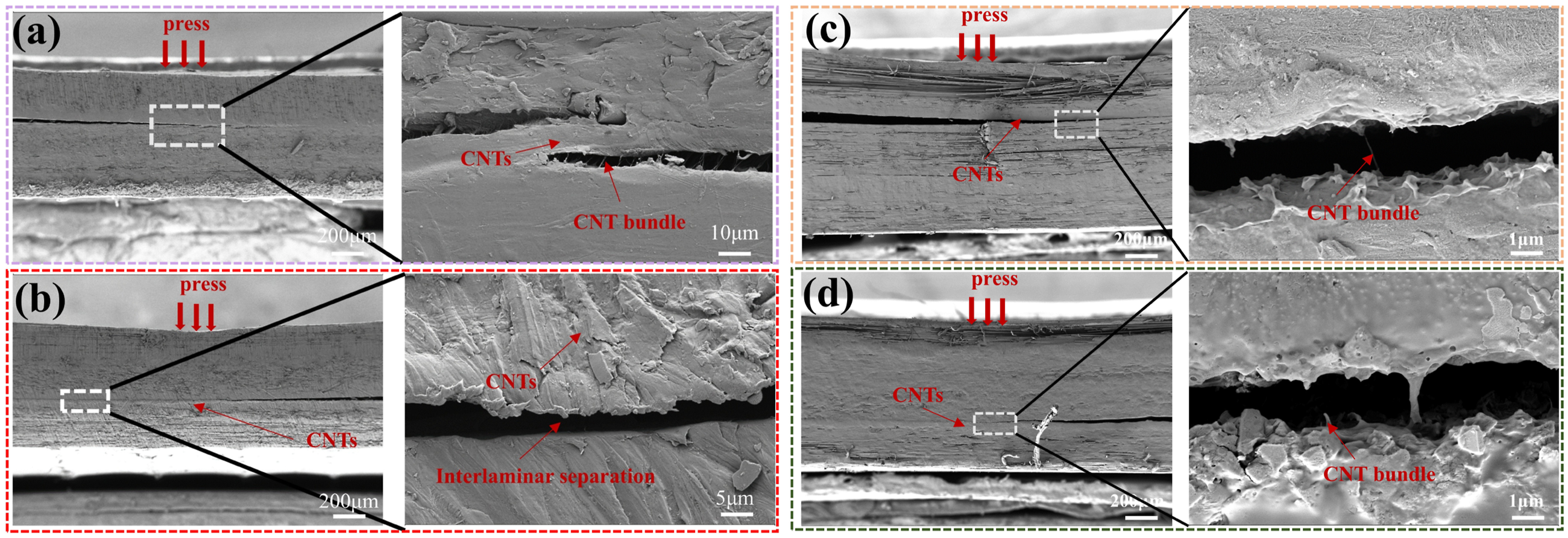
To further validate the toughening mechanism of CNT films, this study investigates the effect of varying the placement of CNT films within the composite stacking structure through a comparative analysis. The stacking configuration and loading methods are shown in Figure 9(a)–(d). In the shear tests, composites CF/CNTs/CF2 and CF/CNTs/CF3 were subjected to different loading conditions. As shown in Figure 10(a) and (c), when shear loads were applied to the single-layer CF/PPS prepreg, although the CNT film somewhat suppressed crack propagation, at higher stress levels, failure occurred at the interface between the CNT film and the PPS resin matrix, with cracks propagating on both sides of the CNT film. In contrast, when shear loads were applied to the double- and triple-layer CF/PPS prepregs, the composites exhibited more uniform crack propagation paths. Figure 10(b) and (d) show that cracks only appeared at the interface between the CNT film and the resin matrix on the loaded side, with crack propagation being smoother and stress distribution more even. These results suggest that the position of the CNT film and the location of the applied load significantly influence the fracture behavior and mechanical performance of the composites. Additionally, in the shear tests with double and triple-layer CF/PPS prepregs, the composites exhibited stronger overall integrity and higher shear resistance, as seen in Figure 9(e). (a-d) Shear test loading diagrams of CF/CNTs/CF2; shear test loading diagrams of CF/CNTs/CF3, (e) Shear stress-strain curves of CF/CNTs/CF2 and CF/CNTs/CF3. (a-b) Shear tests of CF/CNTs/CF2 under load from single-layer PPS-CF prepreg and double-layer PPS-CF prepreg. (c-f) Shear tests of CF/CNTs/CF3 under load from single-layer PPS-CF prepreg and three-layer PPS-CF prepreg.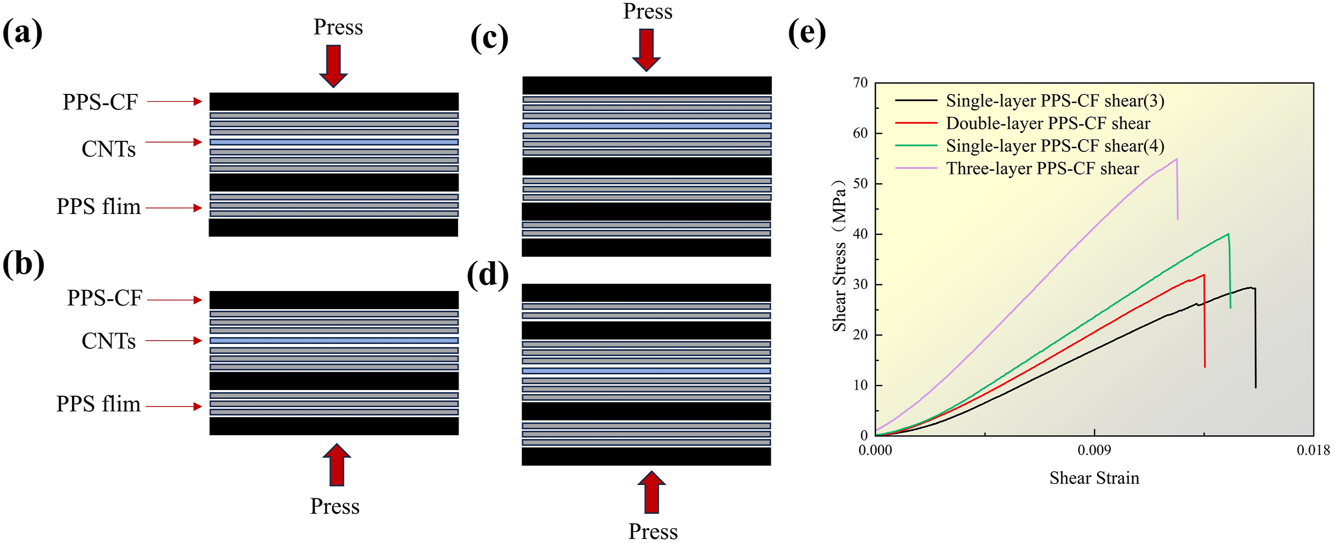
These results indicate that the toughening mechanism of CNT film depends not only on their position within the composite but also on the loading method. By rationally designing the distribution and loading methods of CNT film, the mechanical properties of the composite can be effectively enhanced, particularly under complex loading conditions such as shear and bending. Therefore, future research should explore the optimization effects of different CNT film layers and arrangement structures on composite performance to achieve more efficient material design.
Electrothermal Performance of Composites
Figure 11(a) and (b) shows the temperature variation over time for CNT film and CF/CNTs/PPS composites under different voltage conditions (2 V to 10.5 V). The results indicate that the CNT film reaches a steady-state temperature within about 0.5 seconds after the voltage is applied, with minor fluctuations of ±5°C. As the voltage increases from 2 V to 10.5 V, the power density of the CNT film rises from 0.056 W/cm2 to 1.427 W/cm2, and the steady-state temperature increases from approximately 40°C to over 290°C. In contrast, for CF/CNTs/PPS composites, the CNT film is encapsulated by PPS resin and carbon fibers. The heat must first be conducted layer by layer from the CNT film to the PPS resin and carbon fibers before diffusing to the surface. As a result, the temperature rise of the CF/CNTs/PPS composite is slower, requiring about 80 seconds to reach steady-state temperature. When the voltage increases from 2 V to 7 V, the power density of the CF/CNTs/PPS composite increases from 0.041 W/cm2 to 0.545 W/cm2, and the steady-state temperature rises from approximately 30°C to 215°C. Additionally, the presence of the PPS resin layer isolates the CNT film from the air, further enhancing the thermal stability of the CF/CNTs/PPS composite and significantly reducing temperature fluctuations. (a) Electrothermal testing of CNT film under 2 V to 10.5 V, (b) electrothermal testing of CF/CNTs/PPS under 2 V to 7 V.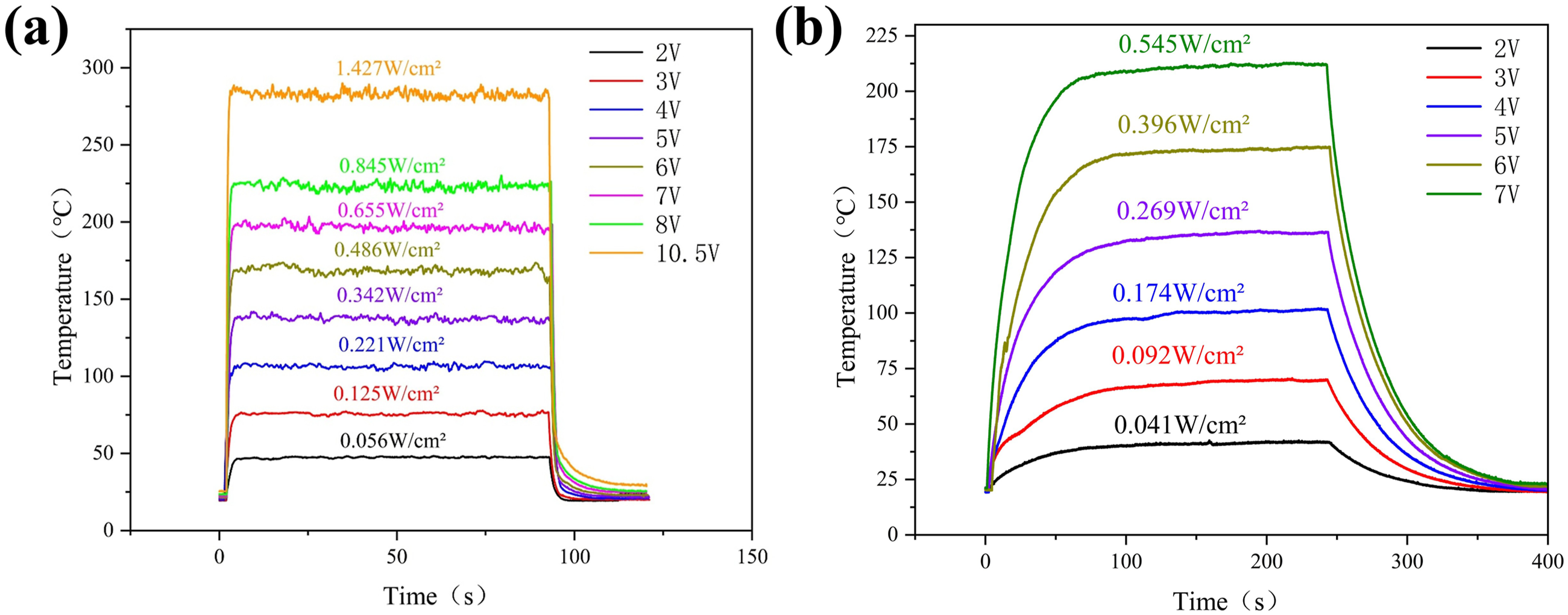
As shown in Figure 12, the steady-state temperature distribution on the surfaces of the CNT film and CF/CNTs/PPS composite materials is presented in three-dimensional heat maps. Figure 12(a)–(c) show that as the voltage increases from 2 V to 5 V, the temperature of the CNT film rises from 45°C to 120°C. The close connections within the CNT film network and between CNTs ensure a uniform temperature distribution from the center to the edges. However, due to the increased contact area of the edge regions with the environment, heat dissipation is faster, causing the temperature in these areas to drop sharply. The electrothermal uniformity characteristics of the CNT film were successfully retained in the CF/CNTs/PPS composite, as shown in Figure 12(d)–(f). When the voltage increased from 4 V to 9 V, the surface temperature of the CF/CNTs/PPS composite rose from 81°C to 206°C, with the temperature difference across the heated area remaining within 5°C. As the voltage increases, the heat generated by the CNT film is effectively dissipated through the resin. The heat transfer distance in the central region is shorter, resulting in higher temperatures, while the heat in the edge regions must travel a longer distance, causing the temperature to gradually decrease and forming a temperature gradient from the center to the edges. (a-c) Temperature distribution of CNT film at applied voltages of 2 V, 4 V, and 5 V, (d-f) Temperature distribution of CF/CNTs/PPS at applied voltages of 4 V, 7 V, and 9 V.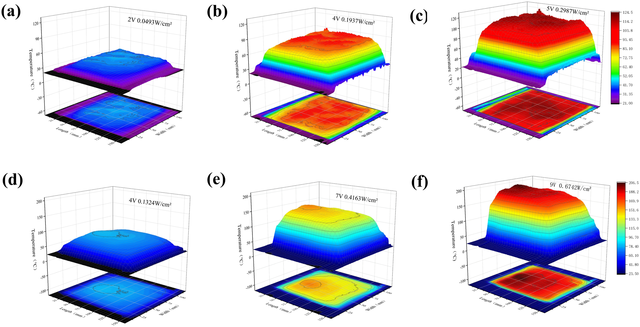
To verify the electrothermal durability of the composites, square wave cyclic voltages were applied to both the CNT film and CF/CNTs/PPS composite. A 7 V voltage was applied to the CNT film for 200 cycles, with a total power-on time of approximately 2000 seconds. For the CF/CNTs/PPS composite, a 5 V voltage was applied for 1700 cycles, with a total power-on time of approximately 113 hours, as shown in Figure 13(a)–(b). The cyclic curves show that, over the long duration of electrothermal cycles, the steady-state temperature of both the film and the composite remained stable, with no significant fluctuations. At the end of the experiment, the film and composite were still able to reach temperatures of 200°C and 150°C, respectively, indicating excellent electrothermal stability. (a) Cyclic curve of CNT film for 100 cycles at 7 V cyclic voltage, (b) Cyclic curve of CF/CNTs/PPS for 1700 cycles at 5 V voltage.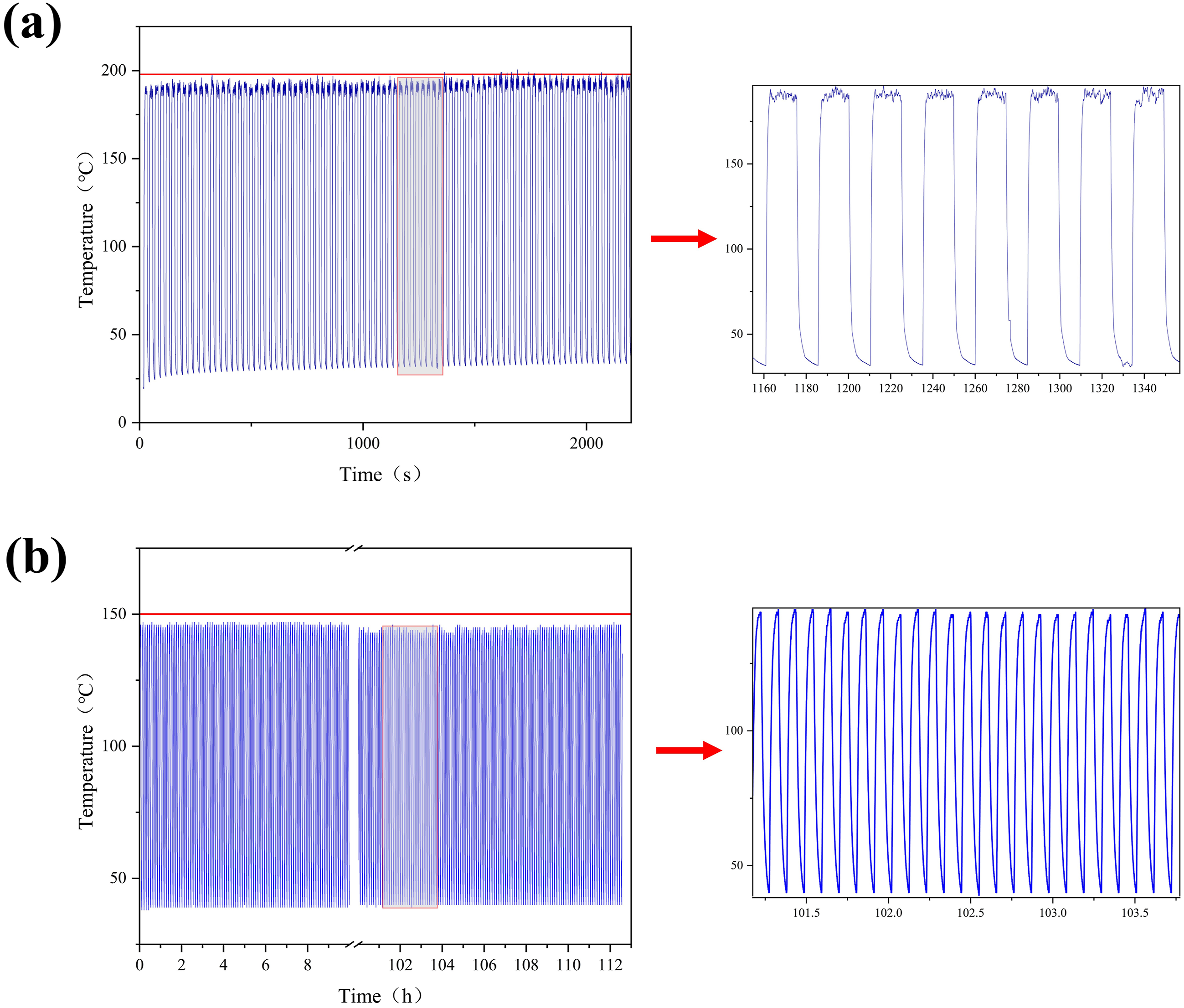
Through systematic electrothermal performance testing, the results showed that the composite material maintained a stable steady-state temperature after prolonged electrothermal cycling, demonstrating excellent electrothermal stability. To further evaluate the long-term performance of the composite, mechanical property tests were conducted on composites subjected to thermal fatigue treatment, and the results were compared with those of composites that had not undergone thermal fatigue. The test results showed no significant degradation in tensile, compression, bending, and shear properties for the composites subjected to thermal fatigue treatment, as displayed in Figure 14. Mechanical testing of CF/CNTs/PPS composites after thermal fatigue.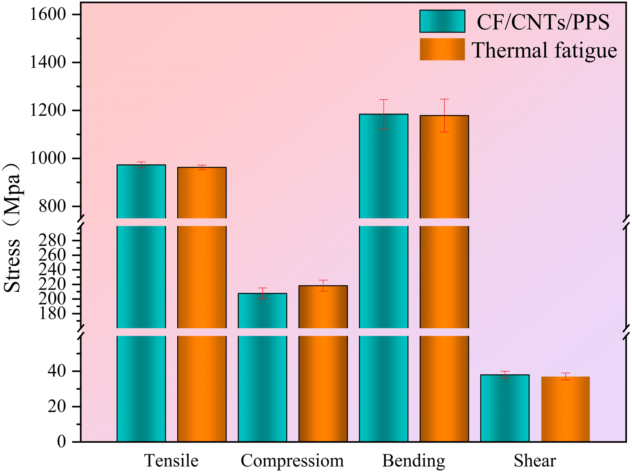
These findings confirm that the introduction of CNT film enhances the electrothermal performance of thermoplastic composites. After electrothermal cycling, the composites retained their excellent mechanical properties, demonstrating good long-term stability, which gives them a potential advantage in electroheating applications. Future research can further optimize the distribution and number of CNT film to improve electrothermal conversion efficiency and temperature control performance.
Conclusion
In this study, CF/CNTs/PPS, CF/PPS, CF/CNTs, and CF composites were prepared using a vacuum hot-pressing process. The effects of CNT film on the mechanical and electrothermal properties of CF/PPS thermoplastic composites were investigated through microstructural characterization, mechanical property testing, and electrothermal performance analysis. The main conclusions are as follows: (1) Thermoplastic composites with excellent overall performance were successfully prepared using the vacuum hot-pressing process. During hot pressing, PPS resin penetrated the CNT film, forming a continuous interfacial transition layer between the CNT film and the composite matrix, with an interlayer thickness of 7.5 μm. However, the interaction between the CNT film and PPS resin hindered the free migration of PPS molecular chains and the perfection of crystallization, leading to a slight decrease in the crystallinity of CF/CNTs/PPS composites. Nonetheless, the crystallinity still meets the standards for PPS-based composites. (2) The macromechanical results demonstrate that the incorporation of CNT films led to a substantial enhancement in the tensile, compressive, and bending properties of the composites. However, the interlaminar shear strength remained unaffected. This is due to the in-plane alignment of CNT bundles, which enhances performance in tensile, compression, and bending but limits shear improvement. Furthermore, the CNT film effectively resists crack propagation, lengthens crack paths, and deflects cracks, dissipating more fracture energy. However, under shear loading, they are more prone to local stress concentration and crack initiation at the interlaminar interfaces. Additionally, optimizing the placement and loading methods of CNT film can further enhance the composite’s mechanical properties. (3) Embedding CNT film enhanced the functionality of CF/PPS composites. Electrothermal experiments showed that the cured composite exhibited uniform temperature distribution, good electrothermal response speed, long-term stability, durability, and resistance to fatigue. This indicates that the CNT film is uniformly and continuously distributed within the composite material, with no signs of local damage.
Thus, the “CNT film embedding layer – vacuum hot pressing” method proposed in this study provides both structural reinforcement and functional integration. It offers new design concepts and process support for the application of thermoplastic composites in fields such as aerospace de-icing, electromagnetic shielding, wave absorption, and structural health monitoring.
Footnotes
Author contribution
Declaration of conflicting interests
The authors declared no potential conflicts of interest with respect to the research, authorship, and/or publication of this article.
Funding
The authors disclosed receipt of the following financial support for the research, authorship, and/or publication of this article: This work was supported by the Aviation Science Funds of China [grant No. ASFC-202200360Q3002], and the Young Scholars Program of Shandong University, Weihai, and Physical-Chemical Materials Analytical & Testing Center of School of Space Science and Technology.
Data Availability Statement
Data will be made available on request.