
Abstract
Carbon Fiber Reinforced Polymer (CFRP) is widely used in aerospace, automotive, and other high-performance industries due to its superior mechanical properties. However, its heterogeneous and anisotropic structure presents significant machining challenges, including high cutting forces, severe tool wear, and poor surface integrity. This paper investigates cutting force modeling and optimization strategies in CFRP machining, focusing on material removal mechanisms, cutting force models, and advanced techniques for efficient, low-damage processing. Key findings highlight that material removal is primarily governed by brittle fiber fracture, matrix cracking, and fiber-matrix debonding. Cutting force models, from macro to micro scale, offer insights into tool-CFRP interactions, although computational complexity remains a challenge. Optimization strategies such as tool trajectory control, Minimum Quantity Lubrication (MQL), and Ultrasonic Vibration-Assisted Machining (UVAM) effectively reduce cutting forces and improve surface quality. Laser-Assisted Machining (LAM) also aids machinability by enabling localized thermal softening. Future research should focus on multi-scale modeling, real-time force monitoring, and intelligent control strategies to optimize CFRP machining further. The integration of digital twin technology and hybrid machining approaches holds promise for improving efficiency and precision. This paper provides a theoretical foundation and practical guidance for advancing CFRP machining in intelligent manufacturing and precision engineering.
Keywords
Introduction
In the rapidly advancing aviation industry, the demand for high-performance lightweight materials, particularly in aviation engines, has become increasingly significant. Fan blades, which are critical components at the cold end of engines, constitute approximately 35% of the total mass of aviation engines.
Achieving high thrust-to-weight ratios and large bypass ratios necessitates the reduction of fan blade mass, a goal primarily addressed through the adoption of lightweight materials.1,2 Carbon fiber reinforced polymer (CFRP), noted for its excellent properties, serves as a prime example of such materials. Comprising a resin matrix integrated with carbon fibers—the reinforcing phase—CFRP components are bonded chemically or mechanically to form a robust interfacial phase, as depicted in Figure 1(a).
3
Based on the type of resin matrix, CFRP is classified into two main categories: thermoset resin-based composites and thermoplastic resin-based composites.4,5 Furthermore, depending on the fiber arrangement, CFRP is categorized into unidirectional, multidirectional, and 2D/3D woven structures, illustrated in Figure 1(b).
6
The material boasts an array of superior qualities such as low density, high strength, impact resistance, and oxidation resistance, showcased in Figure 1(c).7,8 These attributes facilitate its broad application across various high-performance domains, not limited to aviation engine fan blades, car engine hoods, ship propeller blades, and commercial aircraft wings and fuselages, as illustrated in Figure 1(d).9,10 Figure 1 provides a comprehensive overview of CFRP’s composition, structure, properties, and applications. CFRP material (a) compose, (b) structure, (c) property, (d) application.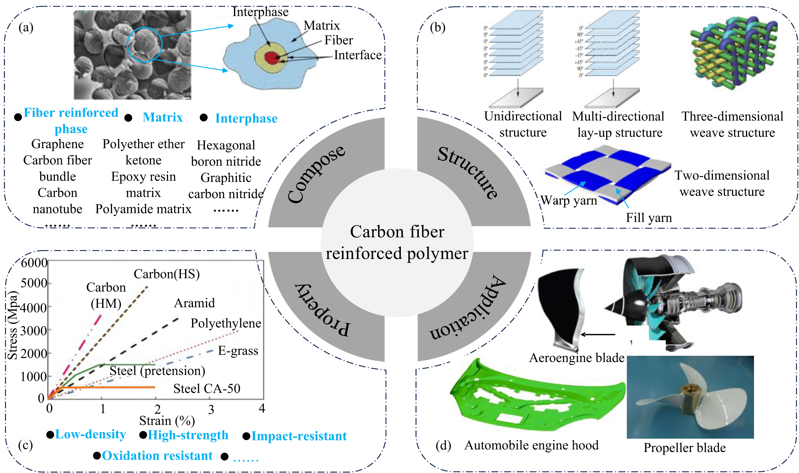
Currently, components made from CFRP are predominantly manufactured using near-net shape molding methods. However, to achieve necessary precision for processing assembly, secondary processing is frequently required.3,11 Milling, known for its strong applicability, high precision, high efficiency, and flexibility, has emerged as an essential technique for attaining the requisite accuracy and efficiency in machining CFRP components. However, CFRP presents significant challenges as a material that is inherently difficult to machine due to several characteristics: Firstly, CFRP is both brittle and hard; carbon fiber hardness can range from 1500 to 2500 HV, which substantially surpasses that of common metals, yet it exhibits low toughness and is susceptible to brittle fractures. 12 Secondly, the material is heterogeneous, consisting of carbon fibers, resin matrix, and interfacial phases. There are considerable differences in the properties of these components, compounded by the diversity in fiber arrangement methods, all contributing to its complex and variable mechanical properties. 13 Thirdly, CFRP demonstrates notable anisotropy; it exhibits significant variability in macro modulus and machining characteristics, 13 which means its milling process markedly diverges from that of traditional homogeneous materials.11,14 This divergence leads to issues such as unstable milling forces, 15 complex machining defects, 16 and severe tool wear. 17 Consequently, the pursuit of high-quality, high-efficiency, and low-damage machining of CFRP has become a critical challenge that demands immediate and focused research attention.18,19 Cutting force emerges from the interaction between the material and the tool during the milling process, serving as a crucial is also a key variable for monitoring this process, ensuring its stability, and maintaining surface integrity.20,21 Through the vigilant monitoring and control of cutting forces, researchers can thoroughly investigate the material removal mechanisms, assess surface integrity, curtail machining deformation, and diminish machining damage. 22 Additionally, heightened cutting forces during the cutting process led to increased deformation and friction, 23 surpassing a specific critical temperature may induce a glass transition in the matrix, potentially causing surface burns. Consequently, the development of a cutting force model and the optimization of milling force control processes hold substantial importance for realizing high-quality, high-efficiency, and low-damage machining of CFRP.24,25
In recent years, the demand for high-performance materials such as CFRP has surged, driving the expansion in its application fields and elevating processing requirements. Current research predominantly focuses on comparing and summarizing conventional and unconventional processes, yet there remains a notable lack of systematic reviews concerning CFRP cutting forces. This paper provides an exhaustive review of global research on CFRP cutting force modeling and optimization control strategies. The main framework of the paper is shown in Figure 2. It begins by addressing the requirements for high-quality CFRP processing, exploring the micro-mechanisms of material removal during milling. The review then progresses to a detailed examination of various CFRP milling force prediction models and outlines optimization strategies for tool structure design, cutting path, cooling lubrication technology, and ultrasonic vibration assistance, among other techniques. The discussion culminates with a summary and identification of future research directions. This research significantly enhances the understanding of CFRP milling mechanics, mitigates machining damage, and promotes the advancement of multi-energy field composite machining technologies. It also offers theoretical support for achieving high-quality, efficient, and damage-minimized machining of CFRP components, thereby encouraging further development and innovation in the field. Schematic diagram of the main framework of the article.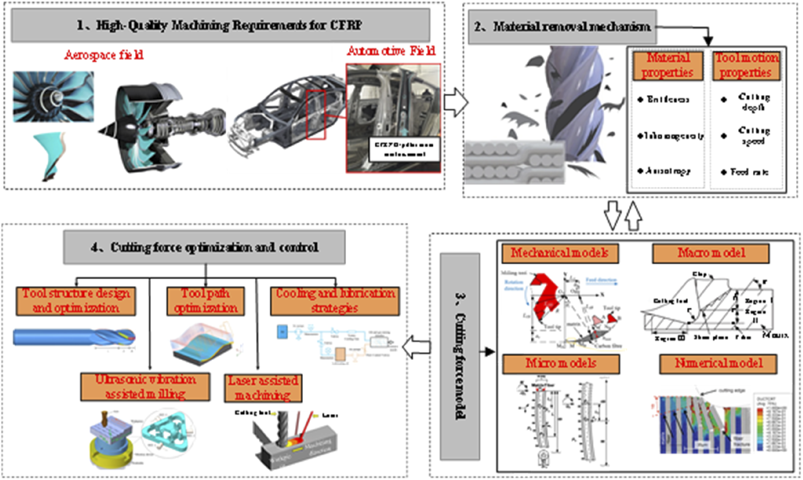
Material removal mechanism
CFRP is a multiphase material composed of a resin matrix, carbon fibers, and interfacial phases. Due to significant mechanical property differences among the individual phases, the interaction between these phases under the action of cutting tools makes the material removal mechanism and damage modes more complex. 26 The orientation of fibers directly influences the overall mechanical properties and deformation behavior of the material, and different orientations of fibers interact differently with the cutting tools on a microscopic level. Moreover, the CFRP milling process involves a complex process of intermittent material removal carried out by multiple cutting edges on the tool. The cutting edges interact with the carbon fibers, resin matrix, and interfacial phases on multiple scales during the cutting process. Therefore, not only the inherent properties of the material itself but also the CFRP material removal mechanisms and tool motion characteristics (such as cutting depth, cutting speed, and feed rate, etc.) are inseparably linked.24,27,28
Material properties
The cutting process involves the synergistic interaction of thermal and mechanical loads, 29 with distinct removal mechanisms depending on the material type. Metals typically undergo plastic deformation through shearing and slipping during the cutting process. 30 In contrast, brittle materials such as ceramics and glass are susceptible to cracking under load, a condition that propagates and culminates in fracture, thereby exhibiting a brittle mode of removal. 31 However, CFRP stands out as a notably challenging material to machine due to its inherent brittleness, heterogeneity, and anisotropy. These characteristics make the cutting process of CFRP substantially more complex and its material removal mechanism significantly more intricate. 32
Koplev et al.
33
conducted through orthogonal cutting experiments on unidirectional CFRP that chip formation primarily results from the material’s brittle fracture. Zhang et al.
34
identified that the primary cause for the appearance of chips as short, broken fibers is due to radial cutting stress surpassing the strength limits of carbon fibers during milling, leading to brittle fracture failures. Su et al.
35
performed milling experiments on plain weave CFRP positioned upright, observing that the weft fibers exhibited five distinct fracture morphologies, as depicted in Figure 3(a). Given that carbon fiber is a brittle and hard elastic material devoid of plastic flow characteristics, its fibers typically do not exhibit a necking phenomenon when fractured, resulting in a distinctly brittle break. Zou et al.
36
further elucidated in their studies that the brittle fracture of fibers can be classified into micro-brittle and macro-brittle fractures. They found that although micro-brittle fracture requires more cutting energy per unit volume of material removed than macro-brittle fracture, it yields a smoother fracture surface.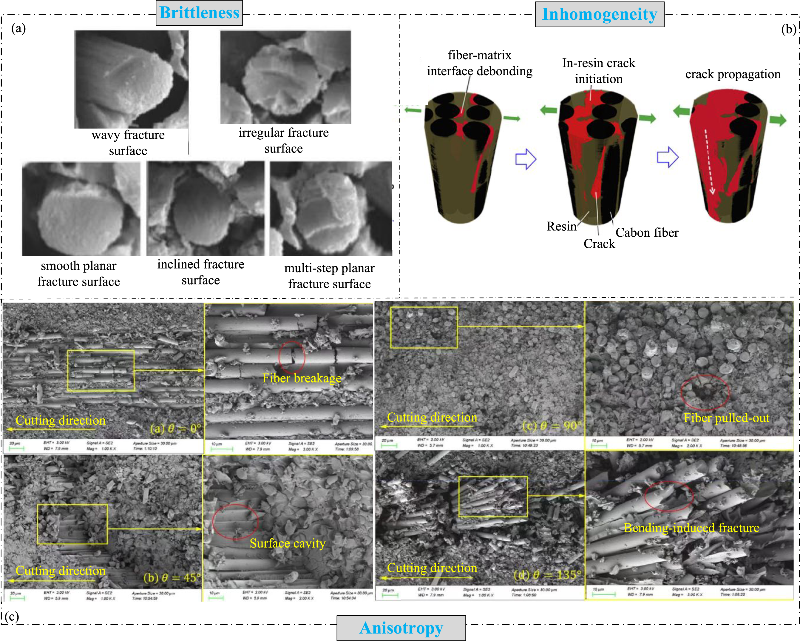
The primary distinction between fiber-rich and matrix-rich regions in CFRP lies in their heterogeneity, particularly under mechanical load, where carbon fibers, resin matrices, and interfacial phases exhibit marked differences in mechanical responses. Given that the bonding strength at the fiber-matrix interface is typically weaker than the failure strengths of both the matrix and fibers, crack initiation during the CFRP milling process generally occurs at these interfaces and propagates along them (Figure 3(b)).37,38 Research by Kimura et al. 39 indicates that the onset and progression of these cracks are significantly affected by the resin matrix’s thickness, especially the resin layer between adjacent carbon fibers. In regions with a ‘thin’ matrix, cracks predominantly advance through debonding at the fiber-matrix interface, while in ‘thick’ matrix areas, they progress through the plastic deformation of the resin matrix. According to Griffith’s fracture criterion, crack propagation follows the path of least energy consumption. Ahmadian et al. 40 have further demonstrated through experimental observations that cracks typically originate and advance within fiber-rich regions, where fiber spacing is tighter and interfaces are more concentrated, and tend to avoid matrix-rich areas.
The anisotropy of CFRP imparts distinct directional characteristics during the machining process, primarily due to the varying mechanical properties dictated by the fiber orientations. This variation significantly influences the material removal mechanisms.32,41 In contrast to unidirectional CFRP, where the cutting edge engages with fibers oriented in one direction, multidirectional CFRP involves interactions with fibers oriented in multiple directions during milling. Rong et al. 42 developed both macroscopic and microscopic finite element models for four typical Fiber Orientation Angles (FOAs) to thoroughly analyze the chip formation process, complementing their study with experiments on the machining surface. Liu et al. 43 elucidated the material removal mechanisms of multidirectional CFRP via orthogonal cutting experiments, noting a transition in the removal mechanisms—from interfacial separation to shear fracture, and eventually to bending fracture—as the FOA varied from 0° to 180°. Ni et al. 44 applied a multiscale finite element model in conjunction with experimental methods to explore the material removal mechanisms in multidirectional CFRP (Figure 3(c)).
Their findings suggested that at an FOA of 0°, where the cutting force aligns parallel to the fiber direction, the fibers exhibit brittle fracture with the fractured parts becoming visible on the machined surface. At an FOA of 45°, the fibers undergo bending and fracturing with interface debonding due to the cutting force, and radial cutting results in cavity defects; however, some of the resultant chips can fill these cavities, enhancing the surface quality. At a 90° FOA, where the cutting force is perpendicular to the fiber direction, the machining process of CFRP is predominantly governed by shear effects and tool compression. At an FOA of 135°, the fibers predominantly endure bending stress, leading to irregular fractures, and the concurrent thermal generation causes the resin to melt and adhere to the machined surface, thus diminishing the surface quality. Zhou et al. 45 conducted experimental research to assess the milling characteristics of twill woven CFRP at different FOAs. Their results demonstrated that the maximum depth of fiber bundle damage escalates with the FOA in the sequence of 0°, 45°, 90°, and 135°.
The findings indicate that CFRP presents complex machining challenges due to its brittleness, heterogeneity, and anisotropy. Material removal mechanisms vary with fiber orientation, transitioning from interfacial separation to shear and bending fractures. The alignment of cutting forces significantly affects fracture patterns, surface quality, and chip formation. Additionally, research underscores the influence of fiber-matrix interactions, resin thickness, and cutting stress on crack initiation and propagation, highlighting the necessity of optimized cutting strategies to mitigate defects and improve machining efficiency.
Tool motion properties
The characteristics of tool motion—encompassing cutting depth, cutting speed, and feed rate—significantly influence the cutting force dynamics during the milling process. Understanding how these factors affect the material removal mechanism is crucial for enhancing machining quality. Research into the impact of cutting depth on material removal, extensively validated within metal cutting domains, provides valuable insights for milling CFRP.46,47
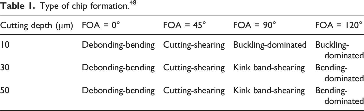
Type of chip formation. 48
Further studies emphasize the influence of cutting-edge radius and depth on machining outcomes. Cai et al. 50 studied precision machining of CFRP, concluded that comparable magnitudes of cutting depth and cutting-edge radius significantly influence the main cutting force, designating the cutting-edge radius as a pivotal factor. Qin et al. 51 observed that cutting depths that are less than or slightly exceeding the fiber diameter impede effective material penetration, causing fibers to undergo compressive fractures from the cutting edge’s squeezing action, which leads to extensive subsurface damage. Liu et al. 52 and Doluk et al. 53 conducted a systematic analysis of the influence of cutting parameters on the surface integrity of CFRP, revealing that an excessively small cutting depth would significantly increase surface roughness due to fiber damage. Kang et al. 54 used orthogonal cutting experiments and a micro-cutting model of CFRP and found that to effectively form a cutting action and reduce surface roughness, the cutting depth should exceed 10 μm. On the other hand, Böhland et al. 55 identified a linear relationship between the undeformed chip thickness and damage formation in their study on CFRP damage mechanisms and optimal machining parameters.
During milling, the cutting speed often reaches the order of meters per second, subjecting the material to dynamic loads. Its deformation behavior differs significantly from that under static or quasi-static conditions. Lee et al. 56 observed through optical experiments that T800/3900B CFRP exhibits rate-sensitive characteristics. Zhou et al. 57 investigated strain rates from 0.001 to 1300 s−1 in carbon fiber tensile tests, revealing that the elastic modulus and tensile strength of carbon fibers remain largely unchanged. Thus, during milling, carbon fiber properties remain stable and are unaffected by cutting speed variations. In contrast, the resin matrix exhibits significant strain rate dependence after curing, playing a crucial role in transferring cutting loads and constraining fiber behavior. 58 Consequently, CFRP inherently experiences strain rate-dependent effects during milling.
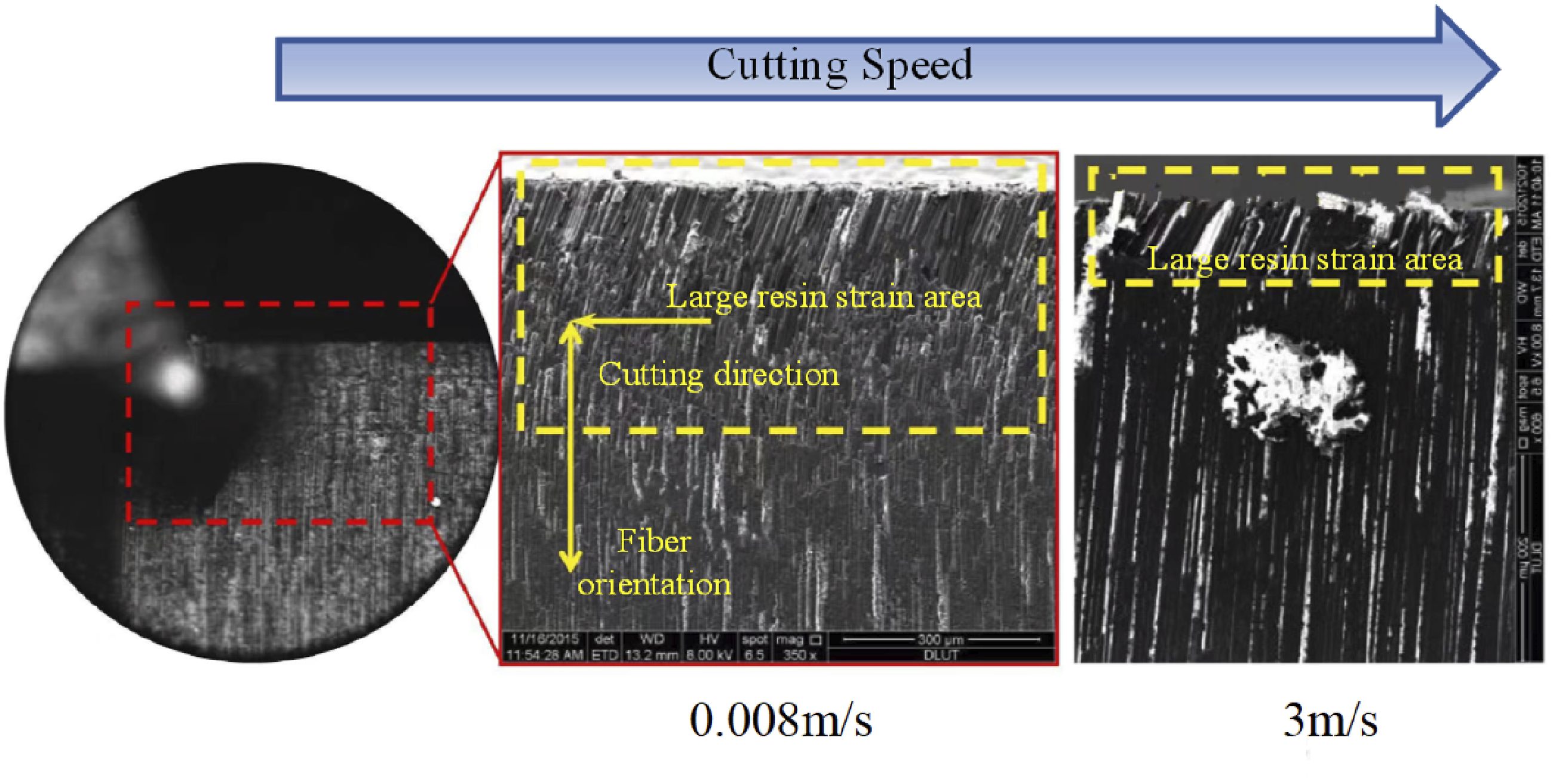
Su et al.
59
investigated the impact of cutting speed on the cutting mechanism of CFRP. As shown in Figure 4, increasing the cutting speed elevates the resin’s strain rate, enhancing the tangential constraints on the fibers. This accelerates fiber failure, causing brittle fracture once the strength limit is reached. Additionally, the improved mechanical properties of the resin reduce pre-fracture deformation, leading to localized damage in the cutting strain region. Wang et al.
60
conducted a comprehensive investigation into the chip formation mechanisms of CFRP under varying strain rate conditions, examining the influence of strain rate on material strength and establishing a coupled model that integrates strain rate effects with fiber orientation. Their study elucidated that chip formation is governed by the interactive contributions of stress and strain rate. Building upon this foundation. Wang et al.
61
developed a macroscopic numerical model incorporating strain rate sensitivity based on the Hashin-Puck failure criterion and an associated evolution law. This enhanced model achieved a 15% reduction in average cutting force prediction error compared to conventional models neglecting strain rate effects, and demonstrated improved consistency with experimental results, thereby enabling a more precise characterization of the cutting process. Strain regions at different cutting speeds.
59
CFRP milling is influenced by tool motion parameters, including cutting depth, cutting speed, and feed rate. Cutting depth variations impact chip formation and fracture mechanisms, with minimal depths producing powdery chips and higher depths inducing tensile deformations. Cutting-edge radius and multi-pass strategies contribute to enhanced machining performance. Cutting speed impacts deformation behavior, with CFRP exhibiting strain rate-dependent effects, particularly in the resin matrix. Numerical models incorporating strain rate effects improve cutting force prediction accuracy.
Cutting force model
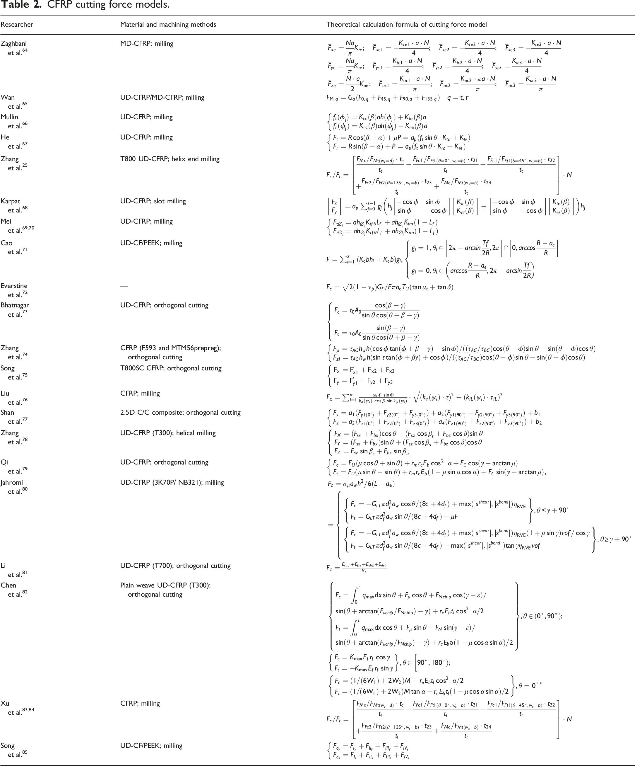
CFRP cutting force models.
Empirical models
Empirical models analyse experimental physical indicators, such as cutting force and tool wear, through data fitting methods. They intuitively reflect the relationship between milling force and cutting parameters, summarizing cutting process patterns. However, these models cannot reveal the underlying milling mechanisms, and their accuracy depends on extensive experimental validation.
Zaghbani et al. 64 utilized a higher-order regression analysis model to estimate the average cutting force of multidirectional CFRP composite materials during the milling process. Wan et al. 65 developed a unidirectional CFRP cutting force model based on multivariate nonlinear regression, capable of predicting instantaneous cutting forces for any layer configuration of CFRP. Investigating chip formation mechanisms under different FOAs, Mullin et al. 66 proposed a cutting force model where the cutting force coefficient follows a periodic function of FOA and introduced a parameter identification method based on average cutting forces. Experimental results showed accurate force prediction, though discrepancies were observed when FOA was 0°.
He et al. 67 analysed cutting and edge effects on cutting force variations, finding that the friction coefficient initially increases and then decreases with FOA, peaking at 55°–70° and reaching a minimum at 5°–15°. Compared to models that neglecting edge effects, this model demonstrated improved cutting force predictions. Zhang et al. 25 proposed a CFRP milling force prediction model that integrates the effect of the end mill’s bottom edge. Through multi-objective optimization, the model effectively suppresses cutting force fluctuations and controls delamination damage, significantly improving the accuracy of machining parameter optimization. Karpat et al. 68 developed a milling force model from slot milling experiments on unidirectional CFRP laminates, showing that maximum shear force aligns with delamination regions, while maintaining a 45° fiber cutting angle enhances surface quality.
In orthogonal CFRP cutting, Mei et al.
69
examined the impact of random fiber distribution on cutting forces, proposing a dynamic milling force model incorporating a Gaussian distribution. Analysis revealed that milling force variations primarily result from instantaneous cutting thickness, random fiber distribution, and FOA fluctuations (Figure 5(a)–(c)). Further, when fiber and cutting directions are fixed (Figure 5(d)), cutting force variations follow a Gaussian distribution.
70
Based on this, Cao et al.
71
developed a high-speed dry milling force model and proposed a two-dimensional joint probability distribution for fiber distribution. Experimental results indicated that carbon fiber is more responsive to milling parameters than the PEEK matrix, validating this model’s feasibility for carbon fiber reinforced polyetheretherketone (CF/PEEK) milling.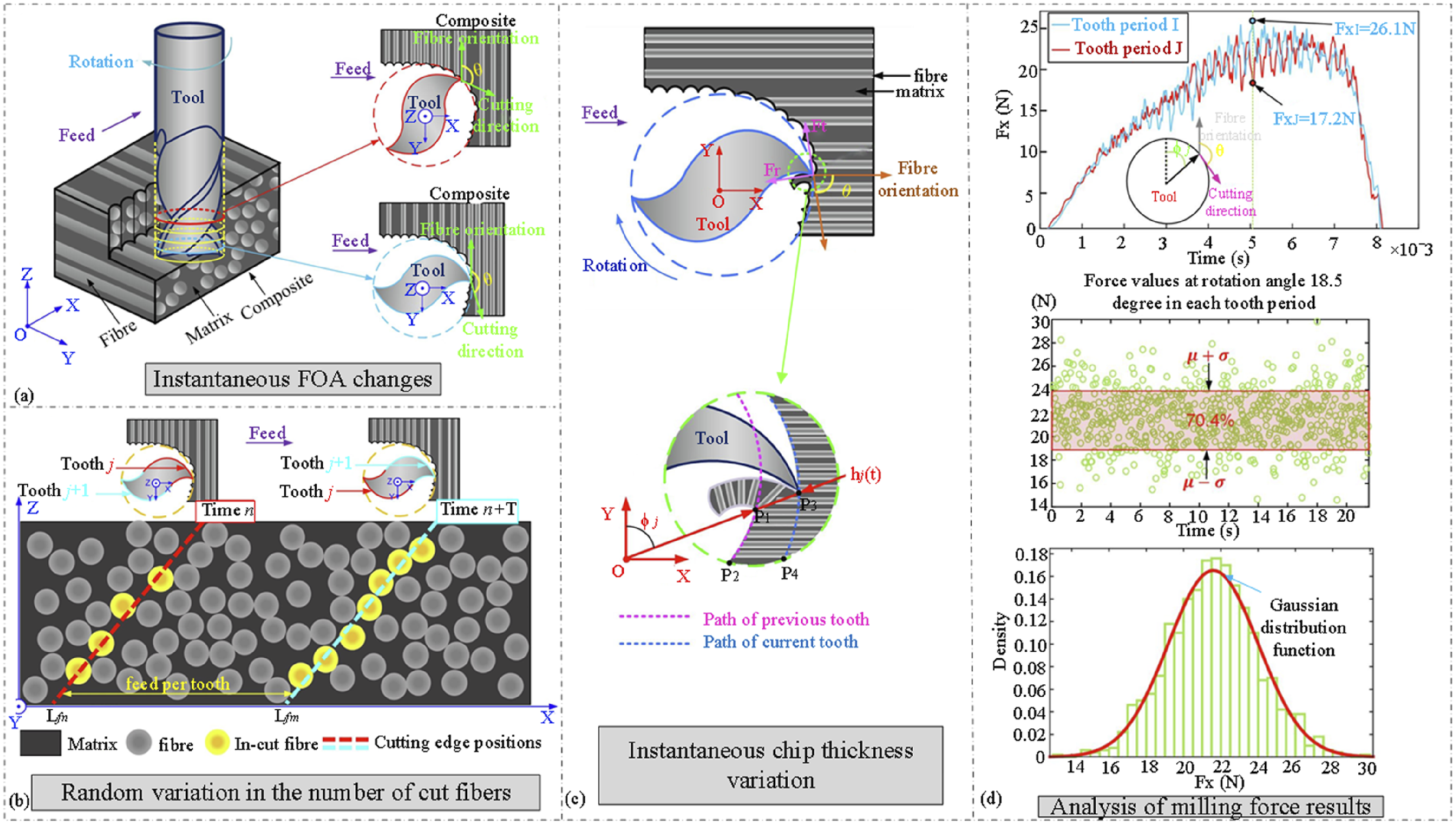
Empirical models, incorporating experimental data alongside theoretical or empirical refinements, demonstrate strong applicability and accuracy, particularly in predicting cutting forces under complex conditions. They are especially useful for rapid estimation of cutting forces in practical machining environments, preliminary process optimization, and parameter sensitivity analysis. However, their predictive capability is inherently limited by a reliance on empirical fitting, and they lack the ability to accurately capture the intrinsic material removal mechanisms of CFRP, particularly when dealing with highly anisotropic fiber orientations or dynamic and variable cutting conditions.
Macro models
Macro models conceptualize CFRP materials as continuous and homogeneous, constructing predictive models of the cutting process based on metal cutting theory.
29
These models fully account for material characteristics, enabling accurate representation of tool-material interactions, thereby optimizing cutting parameters and reducing cutting forces. In 1971, Everstine et al.
72
introduced a CFRP macro cutting force model based on shear plane theory, applicable only when the cutting direction aligned with the FOA. Subsequently, Bhatnagar et al.
73
developed a cutting force model based on the classical Merchant theory. Orthogonal cutting experiments revealed that reversing the cutting direction from positive to a negative FOA nearly doubled the resultant cutting force. Zhang et al.
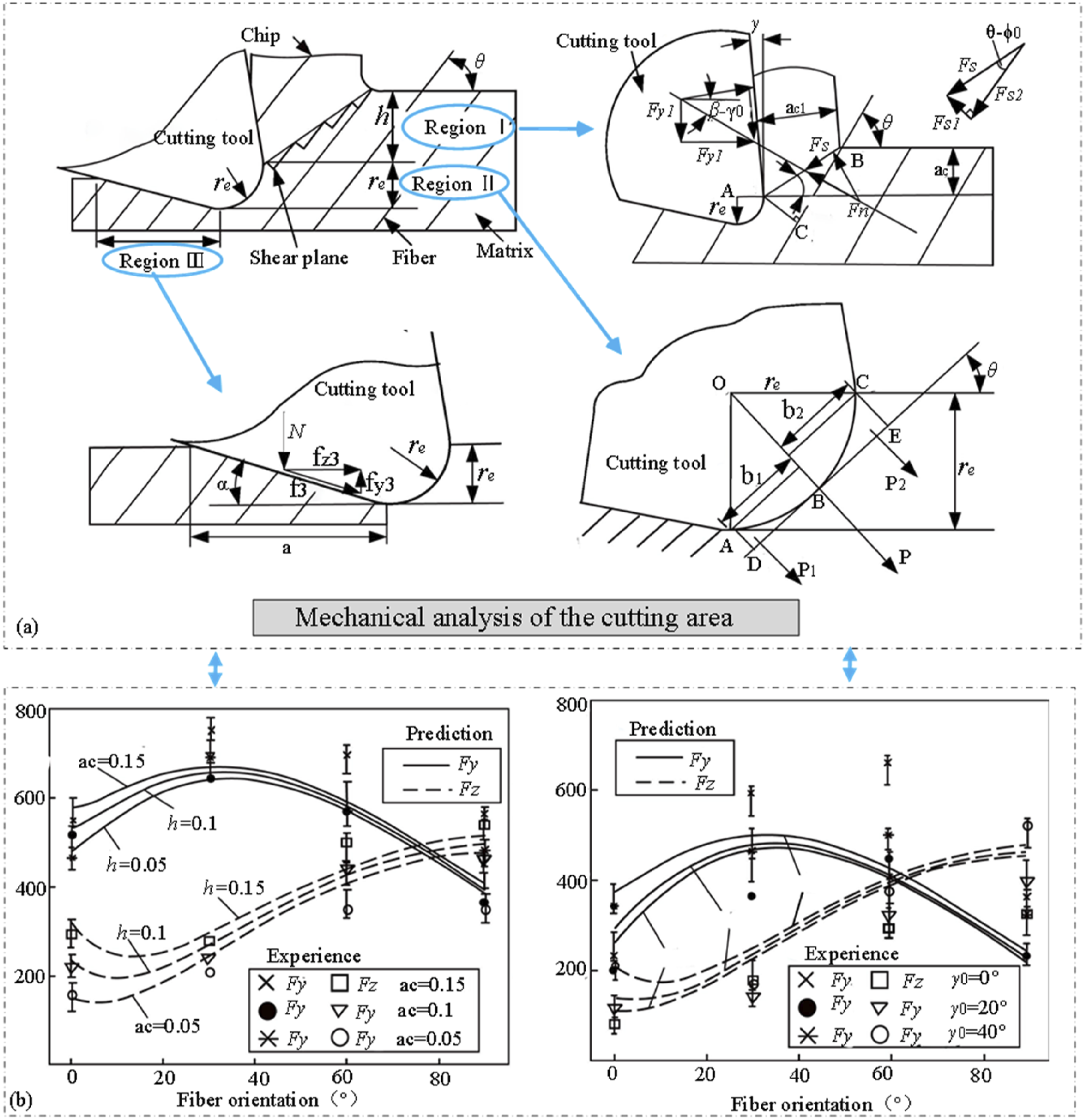
74
proposed an analytical mechanical model that partitioned the cutting area into three zones: cutting zone I (chip zone), cutting zone II (compression zone), and cutting zone III (rebound zone), solving the mechanical behavior of each region separately. As shown in Figure 6, with increasing FOA, the vertical force (F
z
) initially decreases before rising, while the horizontal force (F
y
) first increases and then decreases. Despite maximum errors of 37% and 27% in predicted vertical and horizontal forces, respectively, the model effectively captures key deformation mechanisms. Song et al.
75
developed a macroscopic model based on micro-textured tools to analyze the impact of micro-textures on the cutting zone, and successfully predicted the cutting force of CFRP using the critical shear stress and cutting-shear slip line models. Liu et al.
76
analysed the impact of CFRP material properties and fracture deformation mechanisms on cutting force, and revealed the coupling effect between fracture mechanisms and cutting force under different fiber orientations. Shan et al.
77
refined the model for the cutting process of 2.5D CFRP materials, reducing the maximum error to 10%, as confirmed by experimental validation. Model analysis and result comparison.
74
For the calculation of cutting forces in unidirectional CFRP helical milling, Zhang et al. 78 developed a mechanical model capable of transitioning from micro to macro scales and from static to dynamic states. Their study revealed that increasing spindle speed reduces milling force, whereas a larger pitch results in higher milling forces. However, due to its simplification of failure modes during milling, the model’s applicability remains limited.
Macro-scale models are effective for interpreting the overall cutting force behavior in quasi-homogeneous CFRP composites and provide valuable guidance for initial machining parameter selection. Nevertheless, their assumption of material homogeneity restricts their accuracy when dealing with the highly anisotropic, heterogeneous, and layered nature of actual CFRP structures, especially at extreme fiber orientations or high-speed cutting conditions.
Micro models
Micro models utilize the microscale characteristics of CFRP to capture the fundamental physics of the machining process. Unlike macro mechanical models based on classical metal cutting theories, micro models account for failure mechanisms in chip formation, including fiber-matrix fracture, fiber-matrix debonding, fiber micro-buckling, and bending. These models primarily employ beam theory, representing chips, individual fibers, or representative volume elements (RVEs) as beam structures. They construct mechanical models using linear elastic fracture mechanics, composite material mechanics, or energy-based methods. While micro models accurately predict material behavior during machining and elucidate cutting mechanisms, their application is complex due to the extensive number of parameters requiring experimental measurement and calibration.
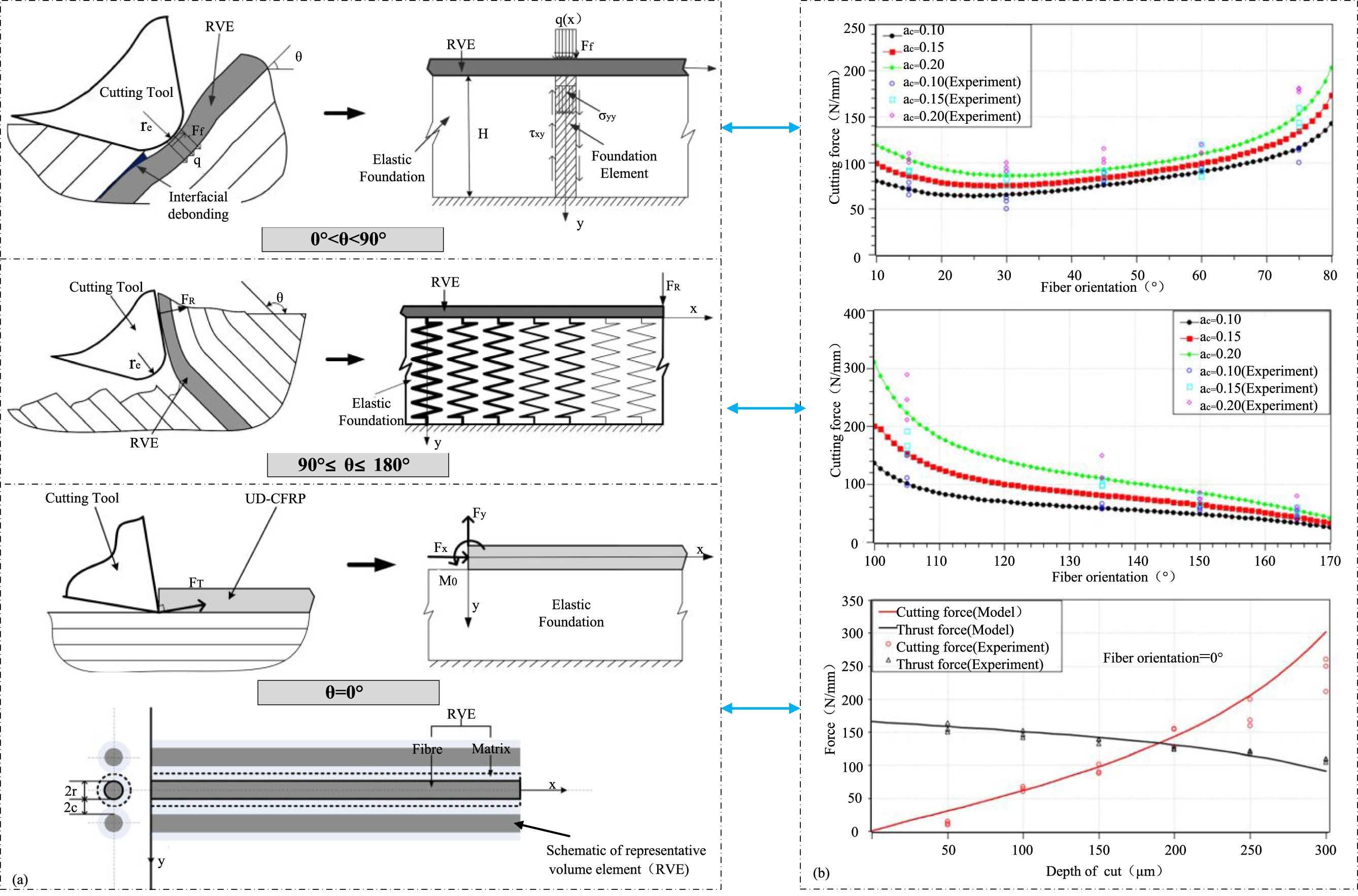
Qi et al.
79
developed a cutting force prediction model for unidirectional CFRP orthogonal cutting at the microscale by analysing three deformation zones—sliding, delamination, and adhesion. By applying the minimum potential energy principle to an RVE comprising a single fiber and its surrounding matrix, they derived the critical cutting-edge force at RVE fracture. Jahromi et al.
80
incorporated external lateral forces, strain energy, and shear energy into an energy balance model to predict orthogonal cutting force variations within the FOA range of 90° to 180°. Simultaneously, Li et al.
81
applied the law of energy conservation to identify energy dissipation pathways in CFRP orthogonal cutting, including surface formation energy, frictional energy at the tool-chip interface, fracture energy in chip formation, and subsurface damage energy. Chen et al.
82
modelled fibre deformation as a beam bending problem on an elastic foundation and developed a cutting force model applicable within the 0° to 180° FOA range. As shown in Figure 7, for 0° < FOA < 90°, the cutting force was determined via shear angle-cutting force integration using Piispanen’s model; for 90° ≤ FOA < 180°, it was calculated using non-uniform Winkler theory. At FOA = 0°, an energy equation was formulated using virtual crack closure techniques to derive the thrust force between the tool face and the chip, elucidating the relationships between cutting force and variables such as FOA, tool face angle, and cutting depth. For multi-fiber hybrid composites, Li et al.
83
established an RVE cutting force prediction model by incorporating multiphase microstructural characteristics. The reliability of this model in predicting cutting forces was validated through orthogonal cutting experiments. Additionally, through up-milling and down-milling process trials, the differential impacts of cutting forces on surface machining quality were systematically analysed.
84
Due to the size effects between carbon fibers and the cutting edges, Song et al.
85
proposed a dry milling cutting force model for CF/PEEK. Experimental validation showed strong agreement with actual data, with a maximum relative error of only 8.3%, highlighting the role of size effects and the composite rope model in explaining CFRP material removal mechanisms. Model sketches and result comparisons under different FOAs.
82
Micro-scale models, incorporating CFRP’s microstructural characteristics, can precisely predict localized damage like fiber fracture, matrix cracking, and interfacial debonding. They also enhance cutting force prediction accuracy by capturing the microscale cutting process physics and accounting for microscopic behaviors in chip formation and material deformation. However, their applicability is limited by a heavy reliance on material-specific microstructural parameters that demand extensive experimental measurement and calibration. Moreover, the high computational complexity and limited scalability to industrial-scale operations restrict their practical use in real - time process optimization and large-scale CFRP machining.
Numerical models
Numerical models employ computational methods to mathematically simulate the cutting process of carbon fiber reinforced polymer (CFRP). Given the high costs of cutting experiments and the challenges such as severe tool wear and poor surface finish, numerical models serve as an effective alternative. They are widely used to analyze cutting mechanisms, chip formation processes, and machining mechanics. Currently, the primary numerical approaches include finite element models (FEM) and discrete element models (DEM). Generally, an increase in model accuracy is often accompanied by an increase in computational time. FEM is based on continuum mechanics and treats CFRP as a continuous medium. It discretizes the material into a mesh composed of elements and constructs a global stiffness matrix through the continuous displacement fields at the nodes to solve macroscopic mechanical responses such as stress and strain. In CFRP machining, by defining the material constitutive relations and boundary conditions, the finite element model can accurately simulate the macroscopic behavior of fibers and the matrix during the cutting process, and is particularly suitable for predicting cutting forces.
For instance, Rao et al.
86
employed FEM to develop a two-phase micromechanical model comprising elastic fibers and an elastoplastic matrix, successfully computing cutting forces in orthogonal cutting and visualizing force generation processes. Calzada et al.
87
introduced continuous elements to model the fiber-matrix interface, accurately predicting cutting forces and chip lengths across various FOAs. Abena et al.
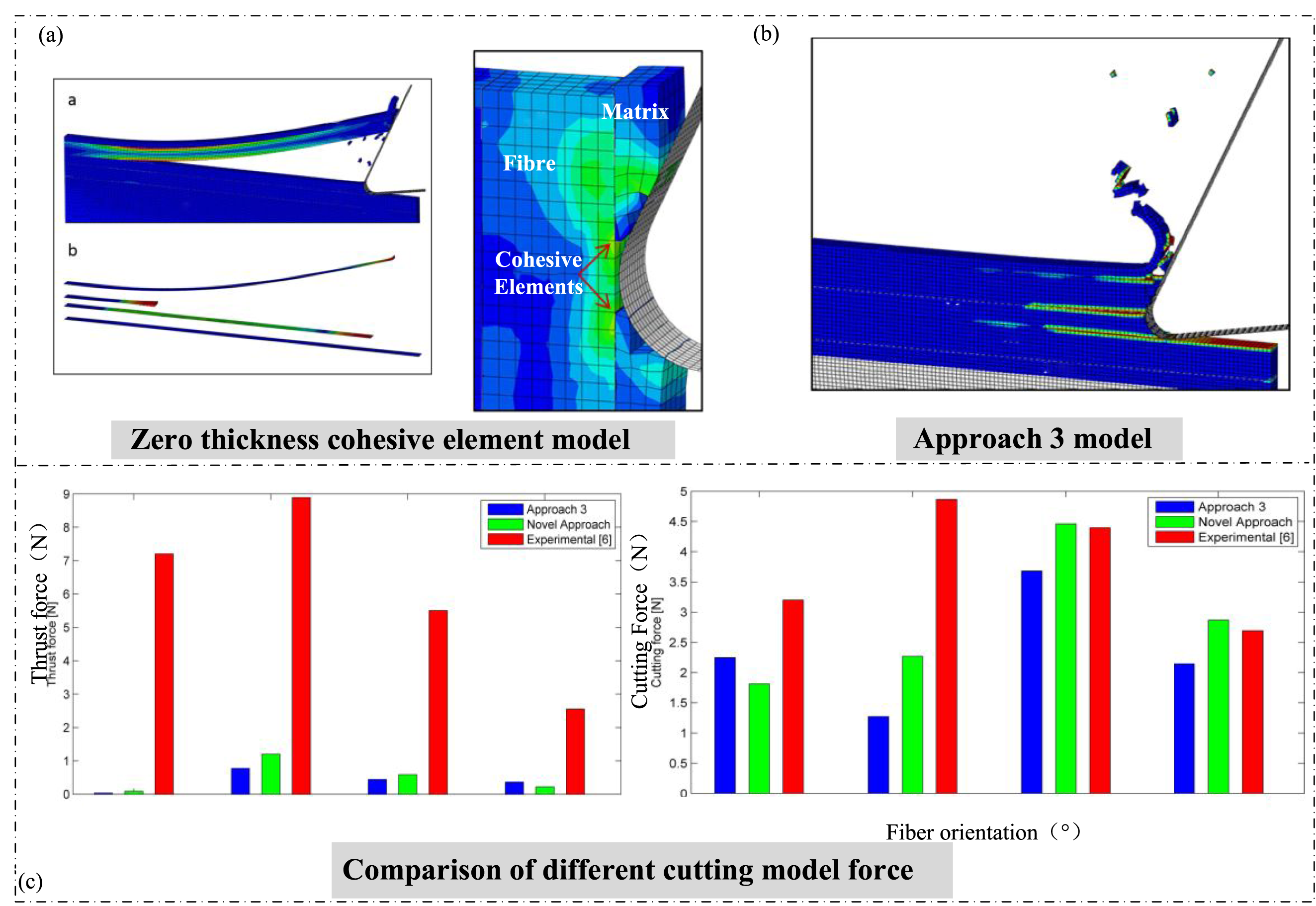
88
proposed a zero-thickness cohesive element model based on a traction-separation law, which, as shown in Figure 8, outperformed surface-based cohesive models in predicting primary cutting forces when compared to experimental data. Cheng et al.
89
developed a thermo-mechanical coupled FEM model, revealing that cutting forces peak at an FOA of 90° and consistently exceed thrust forces. Similarly, Hassouna et al.
90
and Zhang et al.
91
enhanced cutting force prediction accuracy by optimizing machining parameters using FEM models. However, FEM exhibits limitations in cutting force prediction, particularly for thrust forces, as noted by Abena et al.,
88
and requires sophisticated techniques to address discontinuous phenomena such as cracks or delamination. Relying on mesh discretization and implicit algorithms, FEM is ideal for static or quasi-static problems, but mesh distortion can compromise accuracy, and computational costs escalate with mesh refinement. Finite element analysis.
88
DEM is rooted in discrete medium mechanics, modeling CFRP as an assembly of independent particles interacting through contact forces, such as friction, cohesion, or fracture forces. By employing explicit time integration to compute particle motion, DEM captures the microscopic dynamic behavior of fiber fracture and matrix delamination during CFRP machining, providing a microscale perspective on the mechanisms underlying cutting force generation. Iliescu et al.
92
utilized DEM to simulate CFRP machining, reproducing physical phenomena, such as fiber breakage and chip formation (Figure 9), through microscopic particle interactions, thereby indirectly supporting cutting force analysis. Although DEM does not directly focus on quantitative cutting force prediction, its simulation of microscopic failure mechanisms aids in understanding the origins of cutting force fluctuations.
93
Similarly, Wan et al.
94
developed a three-dimensional DEM model for the progressive delamination process in CFRP, incorporating the law of energy conservation and a power-law energy distribution mechanism to successfully simulate the microscopic failure behaviors of Mode I, Mode II, and mixed-mode fractures. Such microscopic insights offer theoretical support for understanding cutting force variations caused by interface failure during machining. DEM model and chip formation process.
92
(a) DEM tool model. (b) DEM workpiece model. (c) DEM simulation and experimental processing.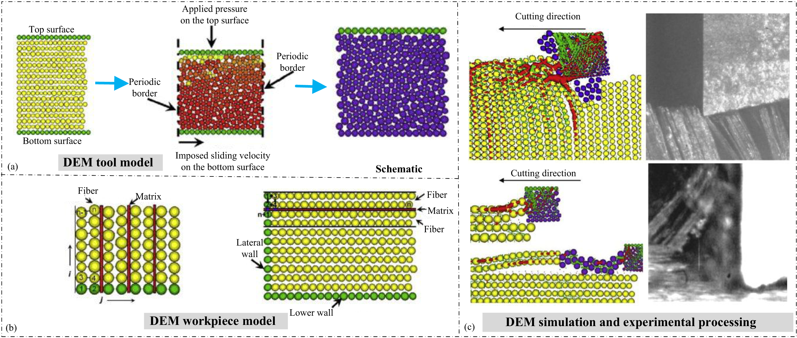
In the simulation of CFRP processing, FEM and DEM stand as two crucial numerical models. They diverge fundamentally in their assumptions regarding material behavior and modeling logic. Rooted in the theory of continuous-medium mechanics, FEM simplifies the carbon fiber cloth as a macroscopic continuous medium. It breaks down the material through mesh discretization and then constructs the global stiffness matrix via the governing equations. Subsequently, it predicts the distribution of continuous physical quantities such as cutting force and temperature field. Conversely, DEM operates within a discrete-medium mechanics framework. It deconstructs the material into individual particles or bonding units. By applying Newton’s laws, it explicitly calculates the contact forces between particles, making it well-suited for the dynamic simulation of discontinuous processes. The finite element method takes the lead in process parameter optimization and macroscopic mechanics prediction. This is mainly due to its well-established commercial software ecosystem and efficient multi-physics field coupling capabilities. Although DEM is constrained by high computational resource consumption, it offers an irreplaceable mesoscopic perspective. This perspective is invaluable for uncovering the physical mechanisms underlying the fluctuations in cutting force.
Cutting force optimization and control
High-frequency variations in milling forces are an inherent characteristic of CFRP machining,69,70 often resulting in material damage that negatively impacts surface quality, assembly tolerances, and may even lead to part rejection. 95 To effectively control cutting forces during CFRP machining, extensive research has been conducted globally, leading to the development of several viable solutions. These primarily include tool structure design and optimization, machining path refinement, cooling and lubrication strategies, and ultrasonic vibration assistance.
Tool structure design and optimization
The abrasive wear action on CFRP materials can lead to premature tool wear, blunting, and coating delamination, which not only shortens tool lifespan but also compromises cutting force stability and machining efficiency. Therefore, selecting an appropriate tool structure and implementing effective optimization measures are crucial for improving machining performance.
Tools used in CFRP machining must exhibit excellent wear resistance to mitigate tool abrasion. 96 Inoue et al. 97 conducted slot milling experiments on multidirectional CFRP using carbide tools, PCD tools, and TiAlN-coated tungsten carbide tools, analysing milling force patterns and tool wear. Duan et al. 98 demonstrated through tool wear experiments that PCD tools not only generate the lowest milling forces but also exhibit the longest tool life, making them highly suitable for CFRP processing. 99 Additionally, Raghav et al.97,100 highlighted that the high hardness and low friction characteristics of tool coatings can significantly enhance cutting performance and extend tool service life.
Xu et al.
100
conducted slot milling experiments on plain weave CFRP and found that diamond-coated tools with CrCN-WS2 coatings—combining the hardness and wear resistance of CrCN with the friction-reducing properties of WS2—exhibited significantly lower cutting forces compared to PCD tools. Zhang et al.
101
further validated the effectiveness of CrCN-WS2 coatings, reporting reductions of 40% in radial thrust forces and 31.5% in cutting temperatures compared to uncoated tools. Chen et al.
102
investigated tool wear mechanisms and milling force evolution, designing a spiral staggered diamond-coated milling cutter (Figure 10(a)). While this tool initially performed well during the coating particle wear stage, a substantial increase in milling forces was observed as wear intensified, leading to coating detachment and a 49.3% increase in tangential forces.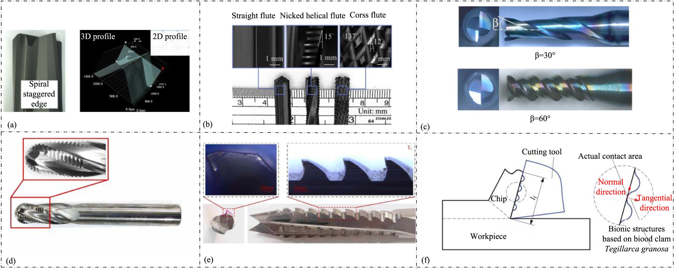
Kuo et al. 103 examined the effects of straight, cross, and spiral groove mill structures on the milling performance of woven CFRP (Figure 10(b)). They found that the interaction between the main and secondary cutting edges in cross and spiral groove mills significantly reduced horizontal cutting forces by 77% and 65%, respectively. Hosokawa et al. 104 conducted side milling experiments using end mills with varying helix angles (Figure 10(c)), demonstrating that both tangential and normal forces decreased as the helix angle increased. For the machining of weakly rigid CFRP curved surfaces, Li et al. 105 developed a discrete edge ball end mill (Figure 10(d)), designed to operate with a smaller tip length while maintaining a constant cutting depth. This approach reduced material removal per tooth and decreased milling forces by 43%. Su et al. 106 introduced a micro-textured tool based on biomimetic principles (Figure 10(e)), confirming its effectiveness in mitigating subsurface damage during CFRP machining. You et al. 107 drew inspiration from the unique geometric grooved network structure of clam shells to design a biomimetic tool (Figure 10(f)). Compared to traditional non-textured tools, this design reduced primary cutting forces by 17.79%, radial forces by 33.92%, and feed forces by 26.48%, validating its feasibility for CFRP machining.
CFRP machining suffers from tool wear and efficiency loss due to abrasive effects. PCD tools offer superior performance with lower cutting forces and longer lifespan. Coatings like CrCN-WS2 enhance durability by reducing friction and cutting temperature. Optimizing tool geometry, such as groove structures and helix angles, minimizes cutting forces. Additionally, biomimetic designs inspired by natural structures improve cutting efficiency and wear resistance, making them a promising approach for CFRP machining optimization.
Tool path optimization
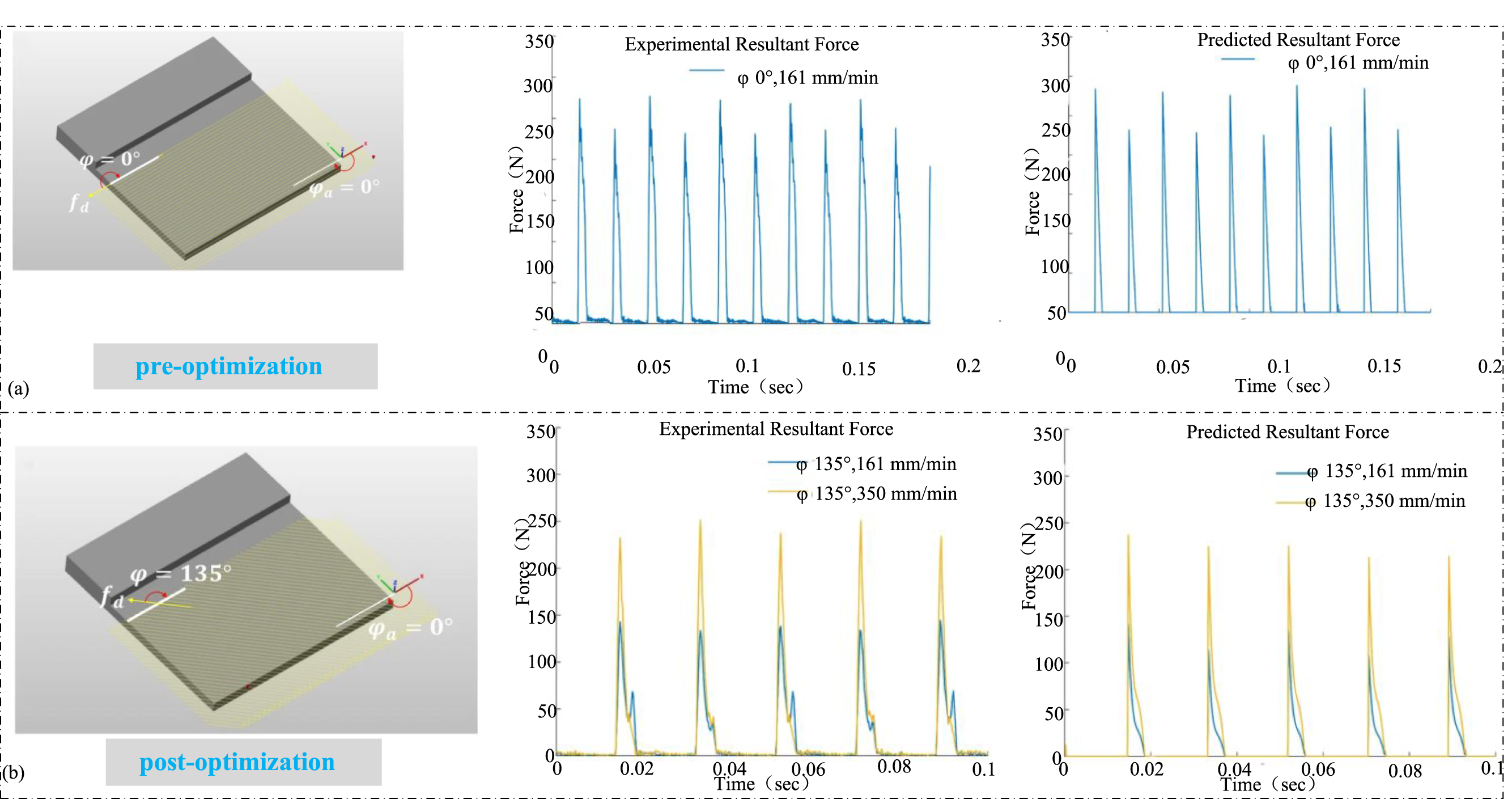
CFRP curved parts often feature complex structures and large volumes, and they require high machining precision. During the milling process of curved parts, the tool path directly affects the quality of the machined parts, thus, optimizing the tool path becomes a key technique to enhance the quality and efficiency of machining CFRP curved parts. 108 By rationally designing the tool path, it is possible to effectively reduce fluctuations in cutting forces, decrease tool wear, and enhance the stability of the machining process. Li et al. 108 proposed a method for selecting tool tilt angles aimed at minimizing machining damage for milling CFRP curved parts, and they verified the effectiveness of variable tilt angle tool trajectories in improving the milled surface quality. Kim et al. 109 proposed a method to determine the tool feed direction (Figure 11), by changing the feed direction to adjust the FOA, thereby minimizing milling forces. Milling experiment results indicated that under optimal feed direction, the cutting force and cycle time were reduced by 54% and 53%, respectively.
Hole-making is a common machining process in the manufacturing of CFRP parts, where traditional hole-making often causes specific machining damages such as delamination, matrix softening, and fiber pullout. Spiral milling, with its continuous spiral feed path, can meet the machining needs of different hole diameters.
110
Sadek et al.
111
noted that in spiral milling, the majority of the tool’s feed motion is tangential, resulting in a 45% reduction in axial force compared to traditional drilling. Amini et al.
112
conducted spiral milling on CFRP materials and found that the tool’s eccentricity and the spiral path help in chip detachment, improving hole-making precision. Wang et al.
113
compared the axial forces under the same cutting conditions for traditional CFRP drilling and spiral milling, showing that the axial force in spiral milling is only 33.97% to 51.23% of that in traditional drilling. Schulze et al.
114
proposed a five-axis oscillating milling method for CFRP, which significantly reduces machining damage by directing the cutting forces inward, although it requires more machining time. Pereszlai et al.
115
compared unidirectional CFRP’s oscillating milling, spiral milling, and conventional drilling techniques, finding that oscillating milling can significantly reduce the number of uncut fibers; furthermore, the precision of CFRP holes made by oscillating milling can reach IT8 grade. Milling forces based on optimized feed direction.
109
Cooling and lubrication strategies
Cooling and lubrication strategies are essential in machining, as they reduce friction at the tool-material interface and prevent tool and workpiece overheating. Due to CFRP’s poor thermal conductivity, heat accumulates in the cutting zone, causing thermal damage and severe tool wear. 116 Implementing effective cooling and lubrication measures is crucial for maintaining workpiece surface integrity and ensuring cutting force stability.
Wang et al. 117 observed that when the cutting temperature surpasses the glass transition temperature of the resin matrix, the surface or subsurface resin in CFRP degrades, compromising fiber support. Additionally, the hygroscopic nature of the resin matrix makes traditional cutting fluid cooling problematic, as it can cause water absorption and expansion, reducing mechanical properties. To mitigate these issues, Seo et al. 118 employed liquid nitrogen as a cryogenic coolant in slot milling experiments on unidirectional CFRP. Their findings indicated that low-temperature conditions significantly reduced the damage coefficient, surface roughness, and cutting temperature, although the overall milling force increased. Morkavuk et al. 119 further demonstrated that cryogenic cooling induced brittleness in CFRP, which helped prevent thermal damage and enhanced chip breaking. However, compared to ambient dry milling, the milling force increased by 45%. Kumar et al. 120 conducted similar experiments and concluded that the increase in milling force under cryogenic cooling was independent of FOA and machining parameters.
To further reduce milling forces and enhance machining quality, researchers have explored Minimal Quantity Lubrication (MQL) (Figure 12(a)) as a green cooling-lubrication technology.120–123 Cococcetta et al.
124
evaluated the milling performance of 3D printed CFRP under dry, cryogenic, and MQL conditions, concluding that MQL significantly minimizes milling forces by improving lubrication at the tool-workpiece interface. Yang et al.
125
further compared cooling-lubrication conditions and found that MQL reduced normal, tangential, and axial forces by 36.12%, 32.64%, and 36.36%, respectively, compared to dry milling. Zhang et al.
126
demonstrated that incorporating graphene-based nanoparticles (Gr-NMQL) into the MQL fluid further enhances friction-lubrication properties, as shown in Figure 12(b), reducing milling forces by 15%∼25%. Additionally, Chen et al.
127
introduced a nano cutting fluid composed omolybdenum disulfide (MoS2) and silicon carbide (SiC) nanoparticles, achieving a 4.78%∼24.84% reduction in milling forces under NMQL conditions. However, due to limited optimization of nanoparticle proportions, the cooling and lubricating performance may not have been fully realized. Wang et al.
128
proposed a cold plasma jet-assisted MQL system, which significantly improved CFRP machinability. The hydrophilic modification effect of the plasma jet enhanced the wetting of the milling area by the MQL fluid, leading to a >10% reduction in milling forces compared to conventional dry milling.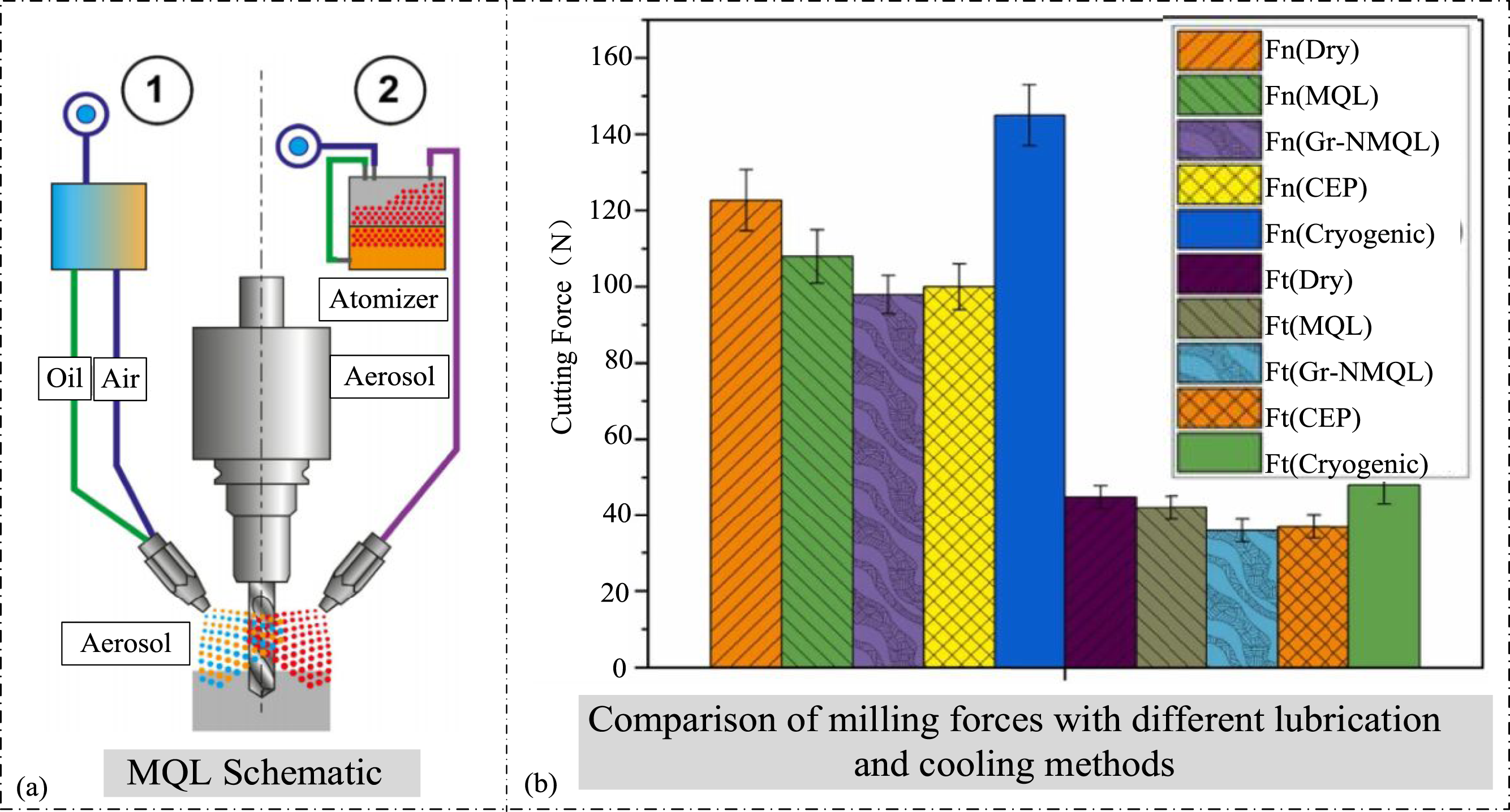
Effective cooling and lubrication are critical in CFRP machining to reduce friction, prevent thermal damage, and stabilize cutting forces. Cryogenic cooling minimizes surface damage but increases milling forces. MQL and nanoparticle-enhanced lubricants improve lubrication efficiency, reducing cutting forces significantly. The integration of cold plasma jets further enhances MQL performance, demonstrating its potential as a sustainable cooling-lubrication strategy for CFRP machining.
Ultrasonic vibration assisted milling
Ultrasonic Vibration Assisted Milling (UVAM) is an advanced machining technique that uses a transducer (e.g., piezoelectric ceramics or magneto-strictive materials) to convert high-frequency electrical energy into mechanical energy, enhancing material removal efficiency.
129
The tool tip undergoes micro-scale amplitude displacements at ultrasonic frequencies, reducing cutting depth, material removal volume, cutting forces, fiber breakage, cracks, and matrix damage.130,131 With advancements in materials and machining, UVAM has evolved from one-dimensional to multi-dimensional modes, (Figure 13(a)–(c)), exhibiting distinct tool movement characteristics and microscopic material interactions.132,133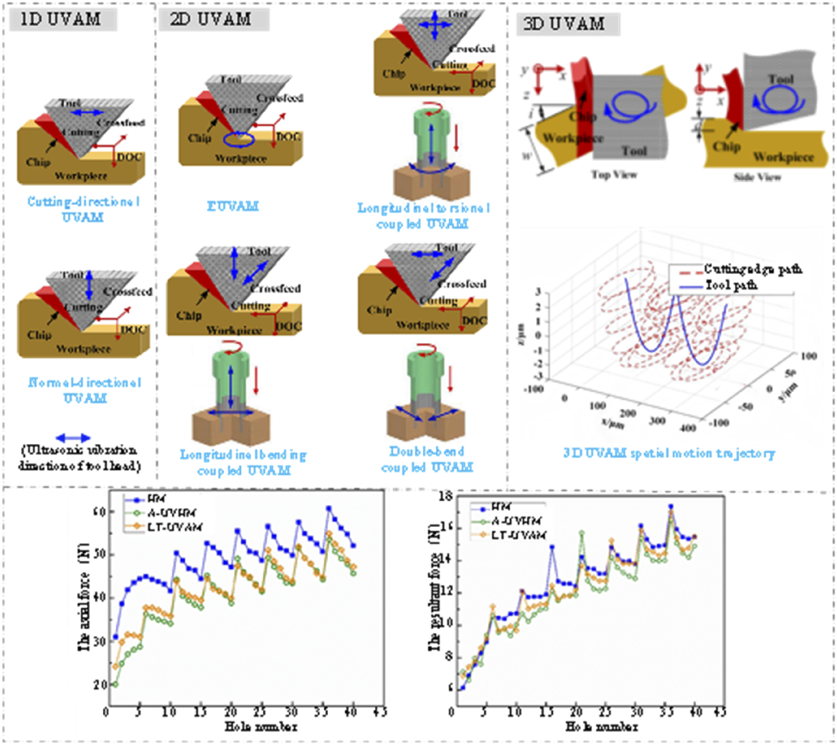
One-dimensional UVAM applies vibration in a single direction, inducing periodic reciprocating motions such as horizontal or axial vibrations.132–134 Ishida et al. 135 demonstrated that combining ultrasonic vibration with low-temperature cooling creates a synergistic effect, significantly reducing thrust forces and suppressing delamination in CFRP machining. Abd et al. 136 found that tool vibration facilitates material removal, lowering milling forces and temperatures by 20% and 15%, respectively; however, axial vibration increased surface roughness. Wang et al. 137 identified that axial ultrasonic vibration induces an eruption effect on the machined surface, compromising quality. To counter this, horizontal vibrations were introduced, effectively mitigating surface roughness issues. 138 Chen et al. 139 developed a macro model for unidirectional CFRP plates using the Hashin failure criterion, replacing traditional cutting loads with horizontal ultrasonic vibration loads. Studies indicate that UVAM reduces cutting forces by 13%–80%, with negligible effects from varying FOAs.
Two-dimensional UVAM applies ultrasonic vibrations simultaneously in both axial and horizontal directions. 132 Common modes include ultrasonic vibration spindles and elliptical ultrasonic vibration-assisted milling (EUVAM), with spindles further classified into longitudinal-torsional, longitudinal-bending, and dual-bending coupled vibrations. 131 Xu et al. 140 analyzed EUVAM’s tool vibration characteristics, finding that axial and horizontal vibrations enhance fiber breakage localization, while the elliptical tool tip motion optimizes machining. However, beyond a critical cutting depth, the influence of tip vibration on fiber-matrix debonding weakens. 141 Geng et al. 142 demonstrated that EUVAM effectively reduces milling forces—up to 43% compared to conventional milling—by utilizing instantaneous FOA changes, intermittent cutting, and superior chip removal. Li et al. 143 proposed a vibration stability model, further validating EUVAM’s superiority in machining brittle materials.
Shi et al. 144 proposed a longitudinal-torsional coupled ultrasonic milling method using a multi-fluted micro-tooth cutter, conducting experiments on CFRP honeycomb structures. High-frequency vibrations facilitated brittle fiber fracture, which reduced average milling force by 23.2% compared to conventional milling. Liu et al. 145 applied longitudinal-torsional ultrasonic vibrations in CFRP spiral milling, demonstrating a 35.7% reduction in axial force, which resulted in vibration-induced directional shear and micro-impact effects (Figure 13(d)). Based on this foundation, Wang et al. 146 indicated that this method can substantially reduce drilling-induced damage in CFRP. Wang et al. 147 utilized high-pulse, intermittent ultrasonic vibrations in CF/PEEK milling, significantly shortening tool-material contact time and reducing milling forces by 4%–54.1% compared to conventional methods.
The tool path in three-dimensional UVAM is formed by harmonic vibrations in the X, Y, and Z directions, generating complex motion trajectories such as elliptical and Lissajous curves. Research on three-dimensional UVAM is still in its early stages. Duan et al. 148 developed a dual-frequency three-dimensional ultrasonic vibration-assisted turning device, demonstrating that cutting forces are positively correlated with cutting parameters. The Lissajous curve trajectory vibrations effectively reduced cutting forces, achieving reductions of up to 59.5% in cutting forces and 44.9% in cutting temperatures compared to traditional turning. Wang et al. 149 designed a non-resonant vibration-assisted milling device and found that vibration amplitude significantly influences milling forces, followed by spindle speed and vibration frequency. Their study also revealed that under vibration excitation, the tool’s trajectory follows a complex helix (Figure 13(c)).
UVAM significantly enhances CFRP machining by reducing cutting forces, fiber breakage, and matrix damage. One-dimensional UVAM improves material removal and minimizes thrust, while two-dimensional UVAM optimizes machining through elliptical tool motion. Although still in its early research stages, three-dimensional UVAM shows promise for further force reduction. Empirical studies confirm UVAM’s effectiveness, demonstrating milling force reductions of up to 80%, underscoring its superiority in enhancing machining quality and efficiency for CFRP and other brittle materials.
Laser assisted machining
Material mechanical properties are highly influenced by temperature variations, which directly impact machinability.116,150 Hard and brittle materials, such as CFRP, exhibit enhanced plastic deformation capabilities when heated. 150 Laser-Assisted Machining (LAM) takes advantage of this thermal effect by locally heating the shear zone, reducing yield strength and improving plasticity.22,151 In recent years, LAM has emerged as a key technique for high-performance machining, offering significant advantages in precision and efficiency. 152
To address the issue of thermal defects in CFRP components caused by laser processing, Chen et al.
153
proposed a laser-assisted numerical control milling method and conducted experimental validation using 10 mm-thick CFRP plates (Figure 14(a) and (b)). The experimental results demonstrated that surface roughness decreased from 8.74 μm to 5.43 μm, and the cutting force was reduced to approximately 9 N. During laser irradiation, the high-energy laser beam rapidly induced thermal pyrolysis and vaporization of the thermosetting resin matrix on the CFRP surface, enabling selective removal of the resin phase, which subsequently reduced cutting forces and machining damage during mechanical milling (Figure 14(c)).
154
Kong et al.
155
performed experiments on unidirectional CFRP using a laser-assisted machining approach and developed an orthogonal cutting simulation model, revealing that LAM reduced the maximum axial force from 77.622 N to 62.253 N while shortening the cutting edge engagement cycle from 0.32 s to 0.18 s. Su et al.
156
demonstrated that during milling after laser ablation, carbon fiber fracture modes transitioned from brittle to ductile, with cutting forces in X-, Y-, and Z-directions decreasing by 59.6%, 59.3%, and 51.2% respectively under identical milling parameters. Another strategy involves maintaining a constant spatial offset between the laser beam and the cutting tool during dynamic machining to achieve synchronized laser-assisted and mechanical milling (Figure 13(d)).
157
Wiedenmann et al.
158
demonstrated that laser irradiation induces localized softening of CFRP (Figure 13(e)), significantly reducing the mechanical and thermal loads on the tool during milling. To prevent excessive thermal damage to the remaining workpiece, precise control of laser power is essential. Park et al.
151
proposed a low-power direct laser-assisted machining (DLAM) approach, utilizing a 4.3 W fiber laser for CFRP flat milling, which reduced cutting forces from 44.5 N to 33.8 N, a decrease of approximately 24%, and improved surface roughness by up to 56%. In side milling, the cutting force was reduced by up to 34%. Xiong et al.
159
conducted dual-robot laser-assisted milling experiments, showing that, compared to conventional milling, laser irradiation softened CFRP plates in the heat-affected zone, leading to reductions in milling forces in the x, y, z directions and the total milling force by 28.02%, 26.31%, 23.68%, and 27.63%, respectively.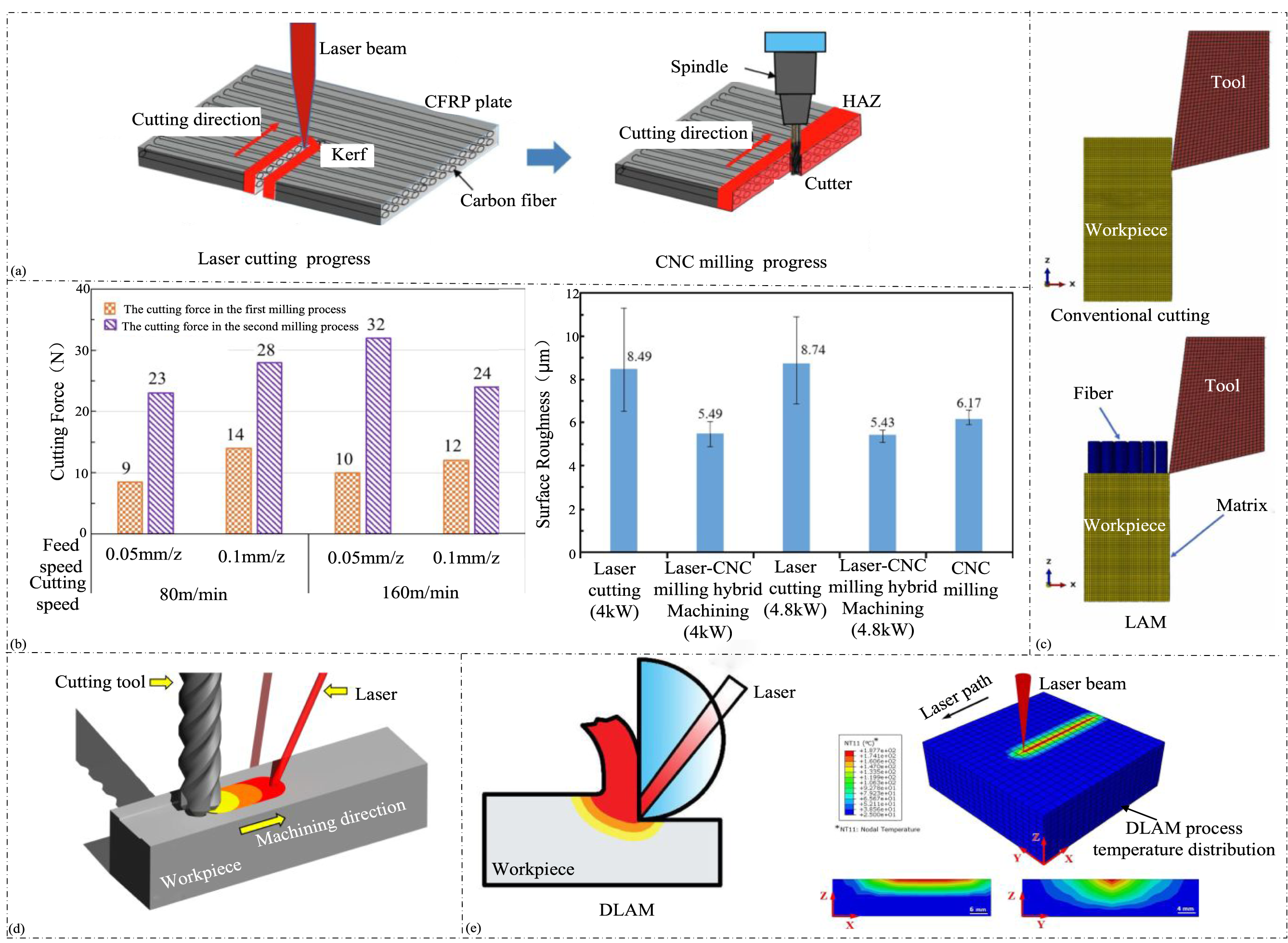
LAM enhances CFRP machinability by locally heating the shear zone, reducing yield strength, and improving plastic deformation. Collaborative laser-CNC processing significantly reduces cutting forces and machining damage, with force reductions up to 67%. Advanced methods like DLAM further minimize thermal effects, lowering cutting forces by 24%–34%. Precise laser power control is crucial to avoid excessive material damage, demonstrating LAM’s effectiveness in high-precision CFRP machining.
Conclusions
In this study, a systematic investigation was conducted into the cutting force modeling and optimization strategies for CFRP machining. The research comprehensively analyzed the material removal mechanisms, reviewed various cutting force models at macro, micro, and numerical scales, and evaluated process optimization strategies including tool geometry design, trajectory planning, cooling and lubrication methods, and advanced assisted machining techniques such as UVAM and LAM.
The major findings reveal that brittle fracture of fibers, matrix cracking, and fiber-matrix debonding dominate the material removal process; multiscale cutting force modeling enhances the understanding of machining behavior; and process optimizations effectively reduce cutting forces and improve surface quality. These findings not only deepen the theoretical understanding of CFRP machining but also offer practical engineering guidance for enhancing machining stability, improving product quality, extending tool life, and supporting the development of intelligent manufacturing for advanced composite components: • • • •
Future trend
As CFRP machining technology advances, it faces both significant challenges and opportunities. Based on the findings of this study, the following areas are identified as critical directions for future research: • • • • •
In summary, while significant progress has been made in the study of CFRP machining, several key issues remain unresolved. Addressing these challenges through interdisciplinary research and technological innovation will be critical for the continued advancement of CFRP processing capabilities, ultimately leading to more efficient, precise, and damage-minimized machining solutions.
Footnotes
Declaration of conflicting interests
The author(s) declared no potential conflicts of interest with respect to the research, authorship, and/or publication of this article.
Funding
The author(s) disclosed receipt of the following financial support for the research, authorship, and/or publication of this article: This work was funded by the State Key Laboratory of High-end Heavy-load Robots (Open Fund Project No. HHR2025020106) and the Natural Science Foundation of Hunan Province (Grant No. 2024JJ7136).
Data Availability Statement
This study is a theoretical review and does not involve original experimental data. All analyses are based on published literature, and relevant mathematical models and parameters can be found in the cited references.