Abstract
This study experimentally and numerically investigated the effect of stacking sequences on the open-hole compressive (OHC) and tensile (OHT) strength and failure mechanisms in carbon-fiber-reinforced thermoplastic (CFRTP) laminates. Specimens with stacking sequences containing a higher proportion of 0° layers and those with more ±45° layers were considered, denoted as “hard” and “soft” specimens, respectively. Strength prediction simulations for CFRTP were conducted using the three-dimensional extended finite element method, previously validated for carbon-fiber-reinforced thermosets (CFRTS). In the OHC test, kink-bands formed before matrix-dominated damage occurred for both hard and soft CFRTP specimens, while the opposite was found for CFRTS specimens due to the higher matrix toughness of CFRTP. Consequently, in soft CFRTP specimens, stress redistribution to the ±45° layers after kink-band formation led to gradual damage progression, achieving a strength comparable to CFRTS despite the higher 0°-layer compressive strength in CFRTS. The OHC simulation effectively predicted CFRTP failure using the maximum stress criterion. In the OHT test, CFRTP exhibited a higher strength than CFRTS in both hard and soft specimens due to the higher 0°-layer tensile strength in CFRTP. The OHT simulation accurately predicted abrupt failure in hard CFRTP specimens using the Weibull failure criterion but underestimated the strength of soft CFRTP specimens. This discrepancy arose because CFRTP exhibited less matrix-dominated damage, allowing stress redistribution to the ±45° layers after fiber breakage, leading to gradual damage progression. X-ray micro-computed-tomography observations confirmed that dispersed fiber breakages progressively connected through splitting cracks and propagated perpendicular to the fibers.
Keywords
Introduction
Carbon-fiber-reinforced polymers (CFRPs) have gained widespread adoption as alternative materials to metals in various industries, including aerospace, automotive, and renewable energy, due to their exceptional mechanical properties and lightweight nature. Traditionally, carbon-fiber-reinforced thermosets (CFRTS), which incorporate thermosetting resins such as epoxy or polyimide as the matrix, have been predominantly used in these applications. Thermosetting resins provide high strength, stiffness, and excellent adhesion, along with superior resistance to solvents, corrosive agents, and heat,1–4 making them suitable for a broad range of structural applications. However, CFRTS also has significant drawbacks, including lengthy processing times and challenges in repair and recycling. Currently, most CFRTS systems are either disposed of in landfills or incinerated at high temperatures, 5 creating substantial challenges related to climate change, global warming, environmental sustainability, and the circular economy. In response to these issues, carbon-fiber-reinforced thermoplastics (CFRTP) have emerged in recent years as a promising alternative for next-generation aircraft structural materials. CFRTPs offer high fracture toughness, exceptional chemical resistance, superior impact resistance, and enhanced damage tolerance. Additionally, they can be manufactured rapidly and in large volumes due to their short production cycles.6,7 Moreover, the thermoplastic nature of CFRTP makes it particularly suited for localized melting and re-solidification processes, enabling joining and repairs through fusion bonding techniques—an approach that is challenging to achieve with CFRTS. This characteristic not only facilitates easier repairs but also enhances the recyclability of CFRTP, 8 thereby establishing it as a material with substantial advantages over CFRTS, particularly in its role as a recyclable material that aligns with the goals of a sustainable society. Furthermore, the outstanding properties of CFRTP have gained increasing recognition, leading to their adoption in aircraft structures in recent years, 9 with broader applications in aerospace structures anticipated in the future.
As CFRPs exhibit anisotropic behavior, they are commonly used in the form of quasi-isotropic laminates. However, under specific design and operational conditions, optimizing the stacking sequence can enhance structural stiffness, failure stress, buckling stress, and failure strain without adding weight.10–13 While the strength characteristics of CFRP can be tailored by altering the stacking sequence, the mechanisms of internal damage initiation depend on the stacking sequence in addition to several other factors, including laminate size, thickness, notch size, and ply thickness.14–22 To ensure an optimized design, it is crucial to understand the failure mechanisms associated with each stacking sequence. CFRP generally exhibits complex failure mechanisms and uncertain material properties due to its manufacturing methods,23,24 necessitating numerous certification tests to account for this variability. 25 Conducting tests for different stacking sequences can increase the number of required certification tests, thereby raising development costs and timelines. To address this challenge, computer-aided engineering evaluations become essential.
When CFRP is applied to aircraft structures, structural components are often fastened with bolts or rivets, resulting in numerous open-holes. These holes create stress concentrations, making it critical to account for this factor in design. Open-hole tension (OHT), open-hole compression (OHC), filled-hole tension (FHT), filled-hole compression (FHC), and bearing tests are commonly used as design criteria for structures requiring mechanical joints. 26 In particular, OHT/C tests are important indicators for conservative design because their strength is lower than that of FHT/C tests.26–29 Therefore, extensive experimental and numerical studies have been conducted to clarify damage progression and failure mechanisms during these tests.17,30–40 Research has also focused on how stacking sequence affects the OHT/C strength characteristics, along with the mechanisms of damage initiation and propagation in CFRTS.18,28,36,41,42 Moreover, research on the strength of CFRTP with open-holes has been conducted for several years. Gail et al. 43 investigated the damage mechanisms associated with compressive failure around open-holes in quasi-isotropic AS4/PEEK laminates. During OHC tests, they performed in-situ observations and post-test electron microscope examinations, capturing the fiber buckling failure process around the open-hole at the microscopic scale. Ding et al. 44 conducted OHT tests on quasi-isotropic AS4/PEEK laminates and performed elastoplastic analyses using the finite element method (FEM). Their experiments revealed that delamination between layers was the primary damage mechanism leading up to ultimate failure, with numerical analyses indicating that this delamination initiated at the edges of the open-hole and propagated perpendicular to the loading direction. Carlson et al. 45 carried out a comparative study of CFRTS and CFRTP in OHT tests to examine differences in failure modes between thermosetting and thermoplastic resins. Their findings indicated that the ductility of CFRTP caused significant necking around the hole in [45/-45]4s angle-ply laminates. As shown in the above studies, although experimental investigations on OHT/C of CFRTP have been extensively addressed, the analysis has primarily focused on stress analysis considering elastoplastic deformation. However, the demand for CFRTP has been increasing, leading to the development of CFRTPs with enhanced mechanical properties in recent years. 46 Consequently, research has shifted toward investigating the laminate strengths of CFRTPs designed for use in aircraft structural components.34,47,48 Recently, Shirasu et al. 34 experimentally and numerically investigated the stress-strain response and damage initiation and propagation mechanisms in OHT/C tests. Han et al. 48 also conducted OHT/C and bearing tests, showing that CFRTP and CFRTS exhibit different failure modes, and experimentally and numerically studied the damage processes in CFRTP. In addition to the aforementioned studies on unidirectional prepregs, OHT/C tests have also been conducted on CFRTP in applications involving automated fiber placement49–51 and 3D printing.37,38,52 These investigations, carried out both experimentally and numerically, highlight the potential of these advanced manufacturing techniques for improving production efficiency and meeting the growing demand for faster manufacturing processes.
Through these studies, both experimental and numerical approaches have elucidated the damage mechanisms in OHT and OHC tests for quasi-isotropic laminates. However, aircraft design requires OHT and OHC strength characteristics for various stacking sequences, as well as highly precise strength analysis methods, which necessitate further validation. In this context, the present study focuses on the following key aspects: • What are the primary damage mechanisms of CFRTP in OHT and OHC tests for various stacking sequences? • How do the damage mechanisms differ between CFRTS and CFRTP across different stacking sequences? • To what extent can existing nonlinear modeling techniques developed for CFRTS accurately predict the deformation field and strength of CFRTP in OHT and OHC tests?
To address these questions, this study conducted OHT and OHC tests on CFRTP (T700G/LM-PAEK) and CFRTS (T700G/2510) with two different stacking sequences: 0°-dominant and shear-dominant. During the strength tests, a high-speed digital microscope was used for in-situ observation of damage mechanisms, while internal damage was examined using X-ray computed-tomography (CT) available in our laboratory. For numerical analysis, the extended finite element method (XFEM), which has been successfully used for the strength prediction of CFRTS with various stacking sequences in previous studies,35,36 was employed to perform strength analysis for CFRTP. The accuracy of OHT/C strength predictions for CFRTP with each stacking sequence was then evaluated. Additionally, microscopic damage around the open-hole in the OHT test was analyzed using X-ray micro-CT at the 3 GeV synchrotron radiation facility NanoTerasu, providing new insights into the 0° damage mechanism in the shear-dominant stacking sequence.
Experimental methods
Stacking sequences of specimens.
Physical properties of specimens.
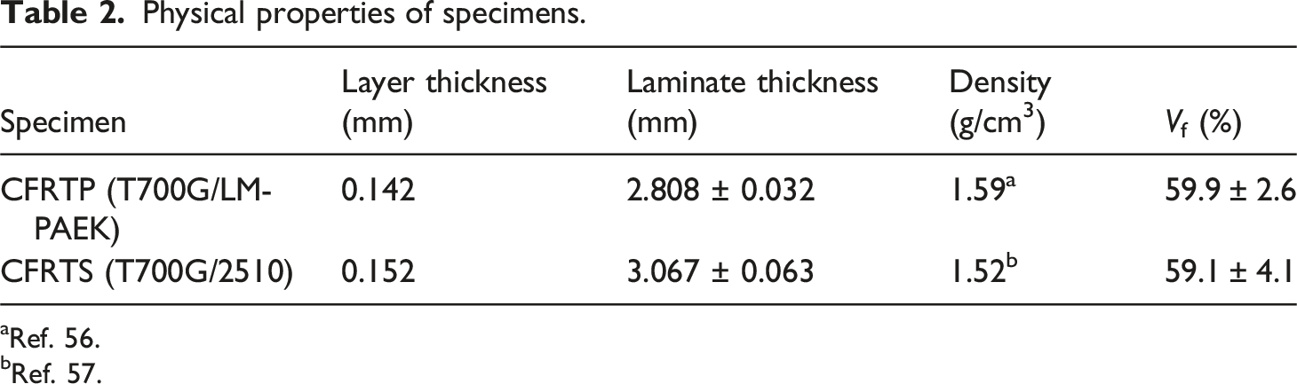
aRef. 56.
bRef. 57.
The OHT/C test setup is shown in Figure 1. The OHT/C tests were conducted following ASTM standards D5766
58
and D6484.
59
Strain in the loading direction was measured using strain gauges (Kyowa Electronic Instruments Co., Ltd.) attached 25.4 mm from the center of the open-hole. The tests were performed on a universal testing machine (5985, Instron) at a crosshead speed of 1 mm/min. In-situ observations of damage around the hole edge were conducted using a high-speed digital microscope (VHX-5000, VH-Z35, KEYENCE Corp.). In addition to strength testing, a stepwise X-ray observation during OHT/C tests was implemented to investigate the occurrence and progression of internal damage during the OHT/C tests. This method involved interrupting the test 10 to 13 times and performing nondestructive inspections using the X-ray CT system available in our laboratory. To enhance the visibility of in-plane damage distribution in the specimen, a zinc iodide contrast agent was impregnated into the damaged areas for these stepwise X-ray observations. Further detailed morphologies of the damaged areas were investigated via X-ray micro-CT at BL10U of the 3 GeV synchrotron radiation facility NanoTerasu, Japan. The X-ray micro-CT system is equipped with a CMOS camera (Orca-Flash4.0 V3, Hamamatsu Photonics K. K., Japan) and a scintillator and optical lens unit with ×10 magnification (AA-51, Hamamatsu Photonics K. K., Japan), yielding a field-of-view and pixel size of 1.3 mm and 0.65 μm/pixel, respectively. For the transmission of the X-ray beam, the damaged areas of the samples were cropped, and X-rays with a photon energy of 15 keV (corresponding wavelength of 0.0827 nm) were used. Experimental setup for (a) OHT and (b) OHC tests.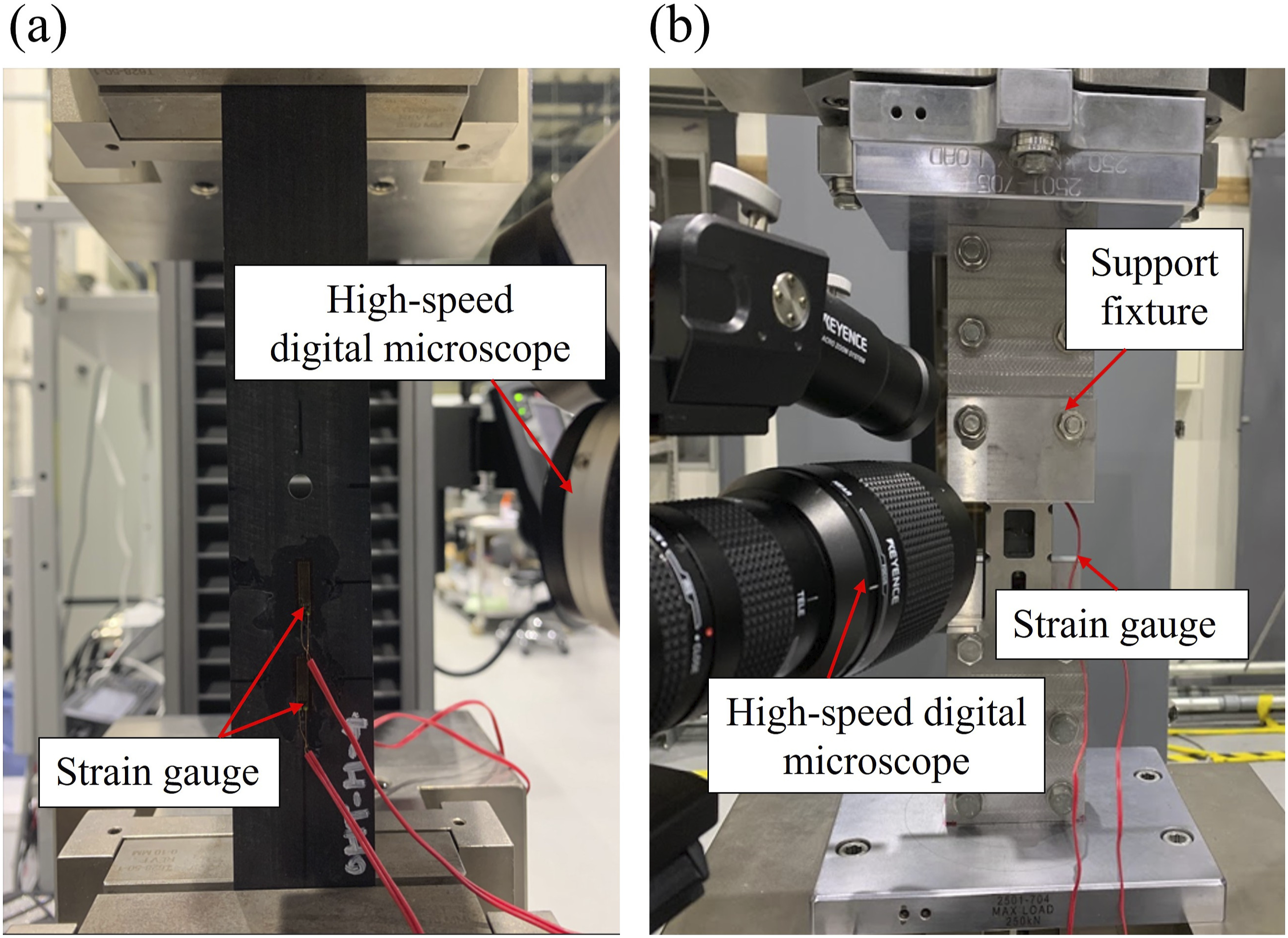
Numerical methods
In this study, OHT/C analysis of CFRTP laminates was conducted using the XFEM to evaluate its applicability to various stacking sequences of CFRTP. XFEM, traditionally applied to the OHT/C analysis of CFRTS, was assessed for its effectiveness in predicting the failure mechanisms of CFRTP. The simulation tool employed in this study is consistent with tools used in prior research.35,36 This tool incorporates various failure mechanisms observed in experiments, including plastic deformation, interlaminar delamination, multiple intra-laminar cracks, fiber breakage, and kink-band formation. However, geometric nonlinearity was not considered in the analysis. Figure 2(a) and (b) illustrate the OHT and OHC analysis models, respectively. The modeling process began by subdividing the two-dimensional characteristic planes of each layer into first-order triangular elements with three nodes. Independently, two-dimensional crack paths were modeled using multiple line segments. These triangular elements and crack paths were then extruded in the thickness direction to create six-node hexahedral elements and crack surfaces. This approach enabled the layer-wise modeling of each laminate, and the three-dimensional analysis model was constructed by connecting the layers using interface elements. Crack surfaces were pre-inserted at locations predicted for transverse cracks in each layer based on prior studies.
34
Because all laminated plates in this study are symmetric laminates, symmetry was assumed for damage occurrence relative to the symmetry plane. To reduce computational costs, only half of the laminate was modeled with respect to the plane of symmetry. The displacement in the thickness direction was constrained to zero relative to the plane of symmetry to maintain symmetry. The dimensions of the numerical models are as follows: the OHT model has a length of 204.8 mm, and the OHC model has a length of 101.8 mm. Both models have a width of 38.1 mm, a thickness of 1.42 mm, and a central circular hole with a diameter of 6.35 mm. The differences in model length from the actual specimens reflect considerations for gripping sections and fixture constraints. Boundary conditions were applied such that the left end was fixed, while a displacement was applied at the right end to simulate the loading conditions in the actual OHT/C tests. Additionally, a thermal analysis was performed before the load analysis to account for residual thermal stresses during molding. In the thermal analysis, free shrinkage due to the coefficient of thermal expansion (CTE) and temperature drop was allowed, while only the rigid body motion was constrained. The thermal analysis was assumed to be linear, and a one-step temperature drop simulation was carried out using the CTE. The matrix of the CFRTP (T700G/LM-PAEK) used in this study is semi-crystalline, and for such matrices, thermal stress accumulation occurs near the crystallization temperature.
60
Therefore, the temperature change was assumed to range from the crystallization temperature of the thermoplastic resin (263°C
55
) to room temperature (23°C), resulting in a temperature difference of −240°C. For the load analysis, a static solver was employed, as the crosshead speed was sufficiently low to be treated as quasi-static. The strain was calculated as the average displacement of nodes within a region corresponding to the strain gauge dimensions, positioned 25.4 mm from the center of the hole. Numerical models using the extended finite element method for (a) OHT and (b) OHC analyses.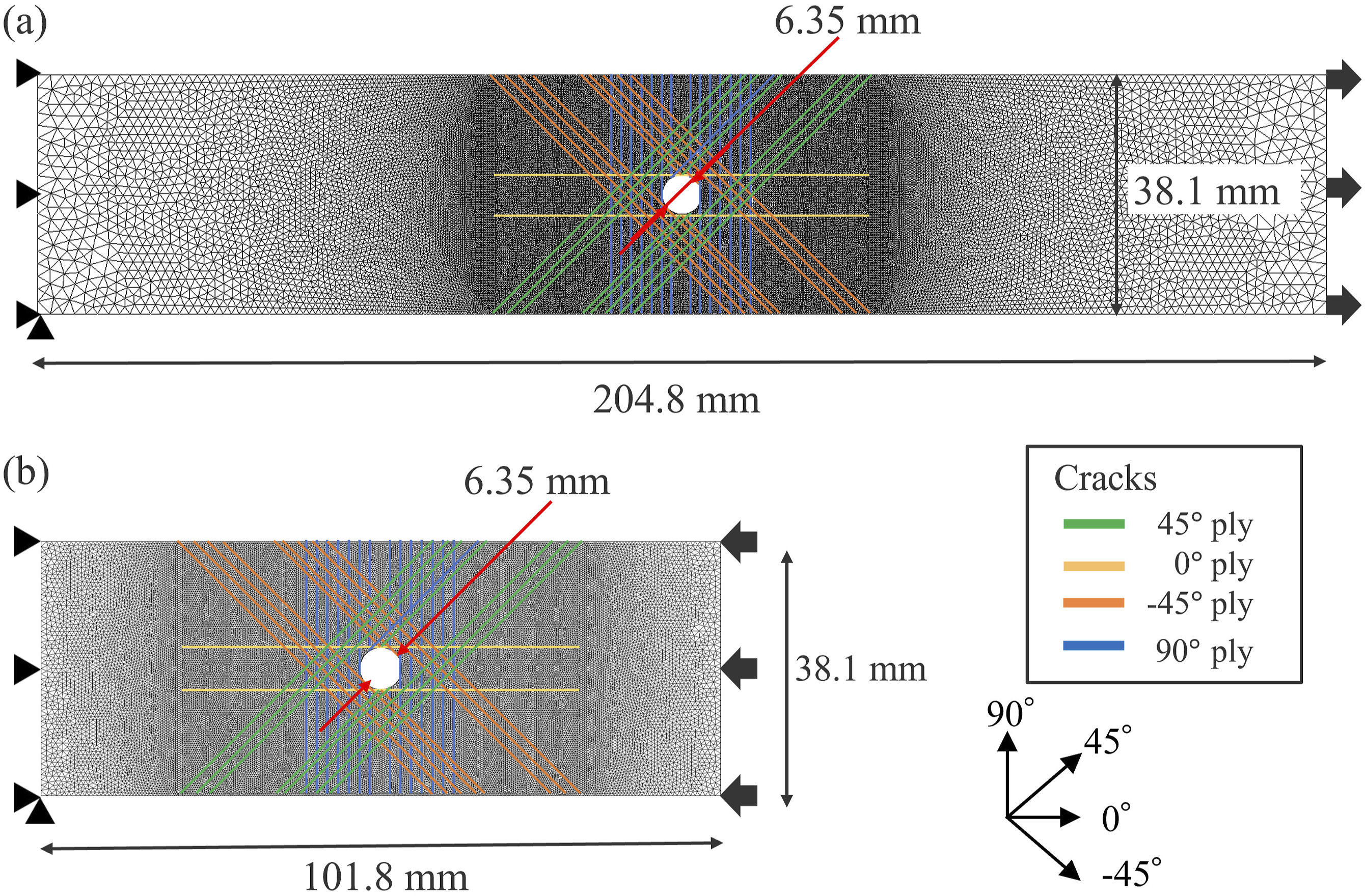
Anisotropic elastoplastic constitutive law
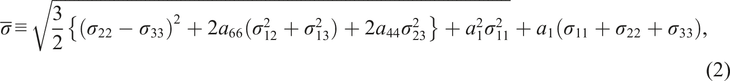
To predict damage caused by matrix-related factors such as plastic deformation, intralaminar cracking, and interlaminar delamination, it is critical to account for the hydrostatic pressure dependence of the matrix resin. Hydrostatic pressure is known to increase the yield stress of CFRP, thereby delaying the onset of cracks and interlaminar delamination. In this study, the hydrostatic pressure dependence of plasticity and cracking in CFRP was modeled separately. The nonlinear behavior due to hydrostatic pressure-dependent plasticity was modeled using the hydrostatic pressure-dependent anisotropic elastic-plastic constitutive model proposed by Yokozeki et al.
61
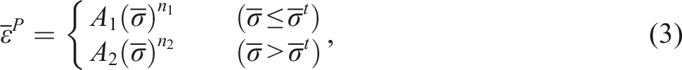
This constitutive model incorporates the unique property of CFRP, which exhibits distinct nonlinear responses under tensile and compressive loading conditions. Within this framework, the total strain increment is decomposed into elastic and plastic strain increments. The plastic constitutive law is represented by the incremental constitutive equation, as described below.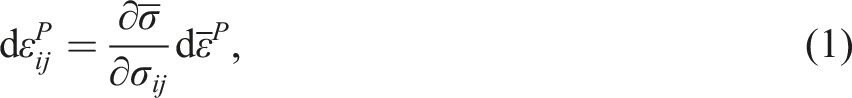
Parameters for plasticity of T700G/LM-PAEK.

Transverse cracks and interlaminar delamination
The hydrostatic pressure dependency of interlaminar delamination and intralaminar cracks was modeled using the cohesive zone model (CZM) proposed by Li et al.
63
This model is based on the Mohr-Coulomb framework and accounts for the increase in shear strength under out-of-plane compressive stress. Interlaminar delamination was modeled by applying the CZM to the interface elements
64
between each layer, while intralaminar cracks were modeled by introducing the CZM to the crack paths inserted independently of the mesh in the quasi-3D XFEM.
65
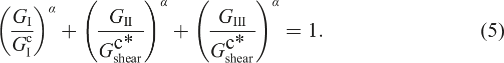
In elements containing crack paths, the discontinuity of the displacement field was reproduced by introducing discontinuous functions at the nodes. Additionally, elements with crack paths were subdivided into subdomains and interface elements for numerical integration. The hydrostatic pressure-dependent anisotropic elastoplastic constitutive law and the kink-band model, described later, were applied at the integration points of these subdomains. The CZM was implemented at the interface elements between subdomains, enabling the modeling of cracks within each layer independently of the mesh while capturing interactions between various damage modes. In the CZM, damage initiation was modeled using the stress criterion (Equation (4)), while damage propagation was modeled using the energy criterion (Equation (5)).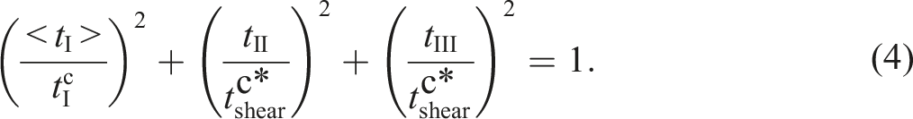
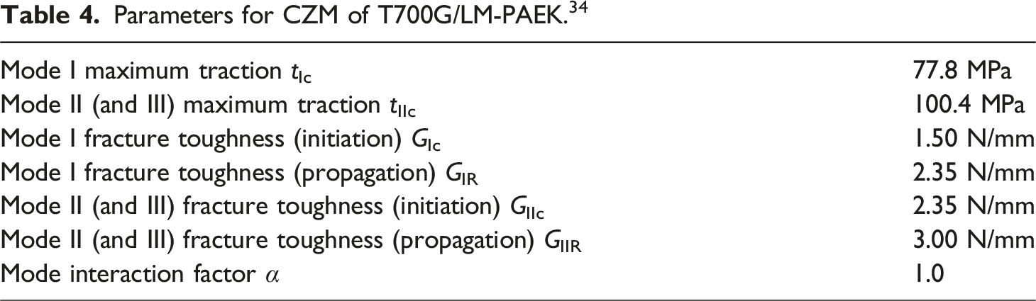
Parameters for CZM of T700G/LM-PAEK. 34
Fiber direction damage model and failure criteria
CFRP typically does not exhibit an ideal unidirectional fiber orientation; instead, it contains an initial misalignment angle. Consequently, under compressive stress, shear stresses develop between the fibers. These shear stresses induce further rotation of the fibers, and as the angle increases, the shear stress also escalates. This cycle continues until the shear stress reaches a critical value, resulting in the failure of the matrix supporting the fibers and leading to the formation of kink-bands.
67
In the OHC analysis, the criteria for kink-band formation were evaluated using two approaches: a simplified version of the LaRC03 failure criterion
68
proposed by Maimi et al.
69
and an approach based on the maximum stress criterion.
70
The LaRC03 failure criterion is determined by the following equation, which is defined by the stress components in the fiber shear coordinate system.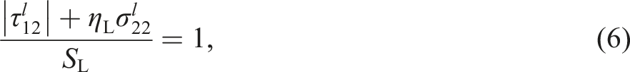
On the other hand, the maximum stress criterion is expressed by the following equation using the longitudinal compressive strength X−.
In fiber direction compression failure, localized kink-band propagation occurs prior to the overall fracture of the specimen, necessitating the modeling of the propagation process. In this study, the smeared crack band model (SCM) 71 was employed to appropriately handle energy dissipation during the propagation process. To prevent convergence issues during the softening process, the zig-zag softening law 66 was implemented, consistent with its use in the CZM. The fracture toughness for fiber direction compressive failure was set at 25.9 N/mm. 72 It should be noted that this value was derived from studies on CFRTS, as the fracture toughness of fiber direction compressive failure in CFRTP has not been investigated in previous research.
Carbon fibers are inherently brittle materials, and their tensile strength is governed by the statistical distribution of defects on the fiber surface.
73
Consequently, the tensile strength in the fiber direction of unidirectional composites composed of these fibers is also expected to follow the statistical distribution of potential defects. To predict the tensile strength in the fiber direction of such unidirectional composites, the Weibull fracture criterion proposed by Hallett et al.
17
was adopted in this study. The finite-element-discretized Weibull fracture criterion is expressed as follows when stress σ is used as the strength index.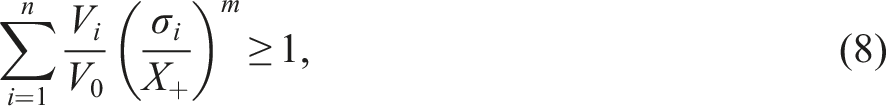
Laminate properties of T700G/LM-PAEK.
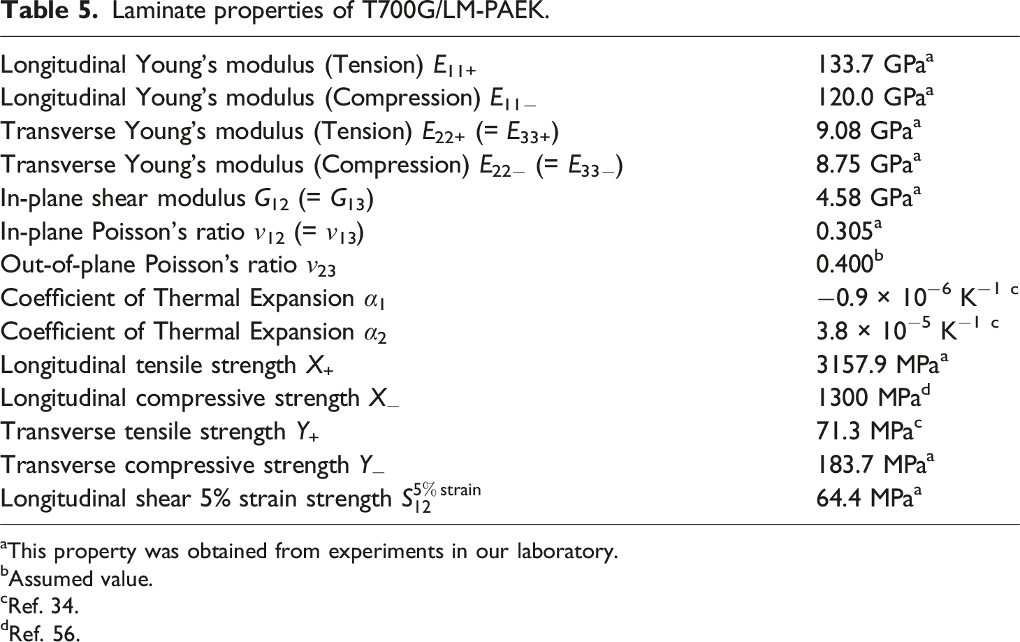
aThis property was obtained from experiments in our laboratory.
bAssumed value.
cRef. 34.
dRef. 56.
Results and discussion of OHC tests
Stress-strain response and strength evaluation of OHC tests
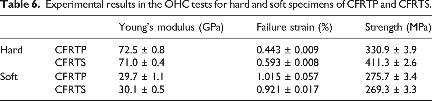
The stress-strain responses of CFRTP and CFRTS in both hard and soft specimens are shown in Figure 3, and the test results are summarized in Table 6. The hard CFRTP specimens exhibited an almost linear stress-strain response up to failure. This behavior is attributed to the limited plastic deformation and the absence of damage until just before failure (refer to the subsequent section for detailed observations). Although Young’s modulus showed little difference between the two materials, as indicated in Table 6, the strength of CFRTP was observed to be 19.5% lower than that of CFRTS. This difference aligns with the relationship between the fiber direction compressive strength of the two materials (CFRTP: 1300 MPa,
56
CFRTS: 1448 MPa
57
). For the soft specimens, nonlinear stress-strain responses were observed for both CFRTS and CFRTP due to plastic deformation. In particular, CFRTP demonstrated pronounced plastic deformation due to the ductility of the thermoplastic resin, which was reflected in its distinct nonlinear behavior. Additionally, the early onset of damage significantly influenced the nonlinearity of the response (refer to subsequent observations for details). Regarding strength, no substantial difference was observed between CFRTP and CFRTS in the soft specimens. Experimental and predicted stress-strain curves of the OHC tests for (a) CFRTP and (b) CFRTS. Experimental results in the OHC tests for hard and soft specimens of CFRTP and CFRTS.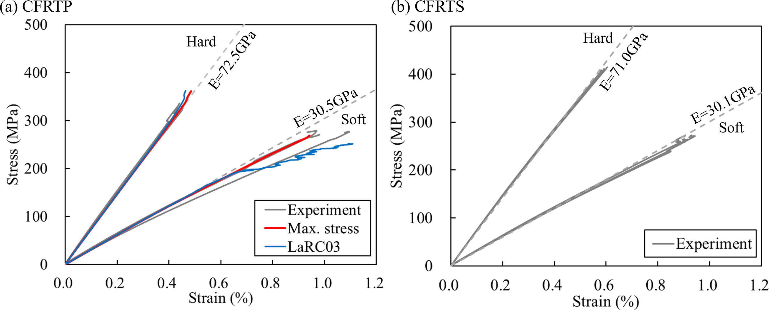
The stress-strain responses of CFRTP obtained from experimental and numerical results are compared in Figure 3(a). Two numerical analyses were conducted using different criteria for kink-band initiation: the LaRC03 criterion and the maximum stress criterion. For the hard specimens, the numerical analysis applying the LaRC03 criterion showed good agreement with the experimental results. However, for the soft specimens, the numerical results showed greater nonlinearity compared to the experimental results. The shear strength used in the CFRTP analysis was measured using the IPS test. Due to significant necking, the shear strength at 5% shear strain was used, which was lower than the shear strength of CFRTS (154 MPa 57 ). This lower value led to the overprediction of kink-bands in the CFRTP system by the simulation with the LaRC03 criterion, resulting in a stress-strain response that exhibited greater nonlinearity. In contrast, when the maximum stress criterion was applied, the numerical OHC analysis showed good agreement with the experimental stress-strain responses for both hard and soft specimens, with an error of less than 10% from the experimentally obtained strength. Based on these results, the maximum stress criterion is suitable for explaining the OHC strength of CFRTP. However, it is important to account for fiber micro buckling around the initial misalignment angle when discussing the mechanism of kink-band formation. As proposing a new criterion for kink-band formation that accounts for fiber micro buckling and reproduces the experimental results for the soft specimens of CFRTP lies beyond the scope of this study, such a criterion is not proposed here. Instead, a discussion on the failure envelopes proposed by LaRC03 and Camanho et al. 74 has been included in the Appendix. The following sections will present detailed observations of damage around the open-hole and discuss the damage evolution.
Progressive damage in OHC tests
The in-situ observation results from the OHC tests are presented in Figure 4. Comparing the damage behaviors of CFRTP and CFRTS in the hard specimens, CFRTP (Figure 4(a)) exhibited no clear splitting cracks before failure; only the formation of kink-bands was observed. In contrast, CFRTS (Figure 4(b)) exhibited the onset of splitting cracks, and they propagated along the loading direction. In addition, due to the immediate formation and growth of the kink-band, it was impossible to capture the destruction process with a high-speed microscope (operating at 60 fps). This is due to the low fracture toughness of CFRTS for fiber direction compressive failure, which causes small kink-bands to initiate and propagate rapidly. In other words, CFRTP is suggested to have higher resistance to crack growth during compression failure compared to CFRTS. In-situ microscope observation results in OHC tests for hard and soft specimens composed of CFRTP and CFRTS.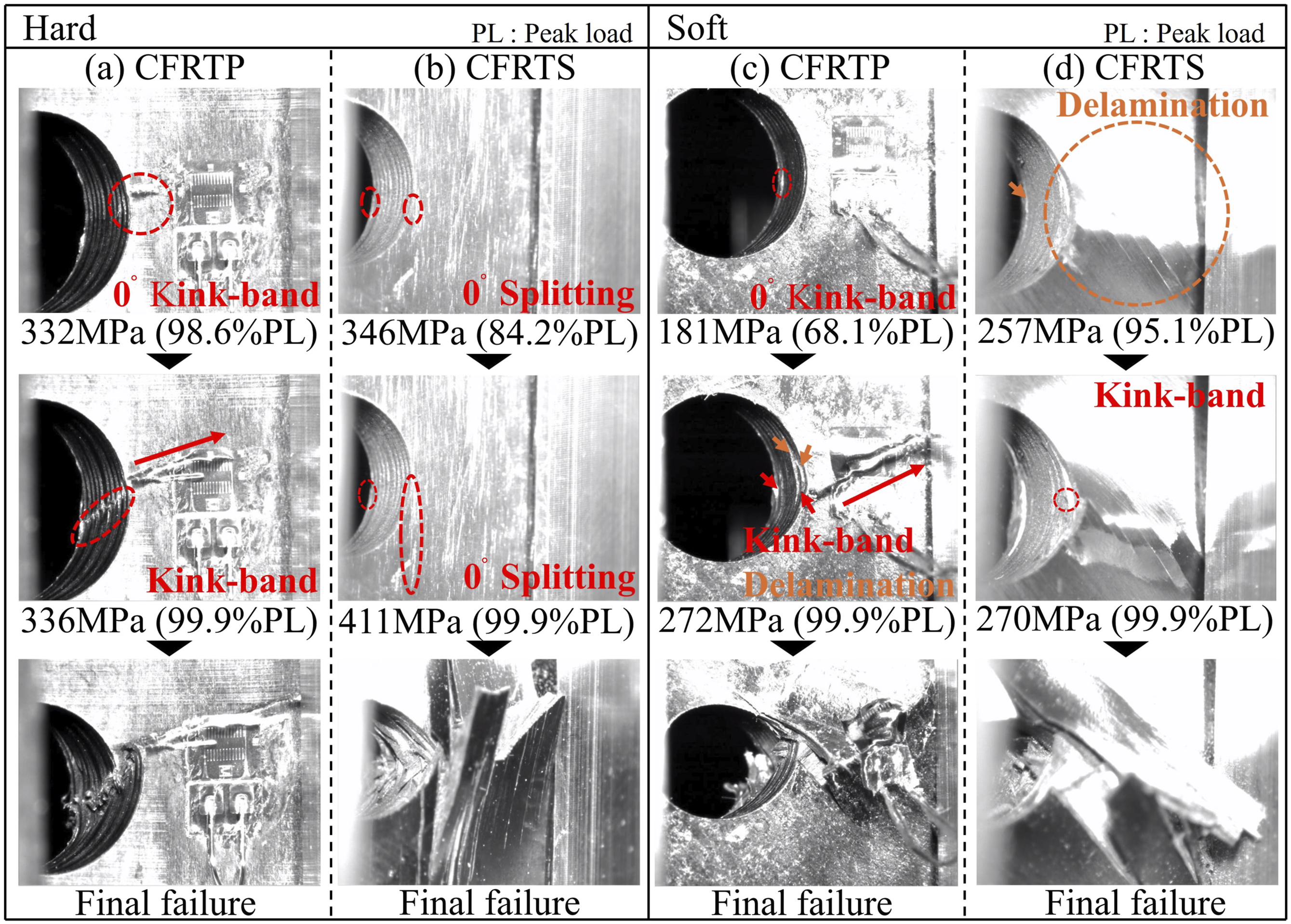
The in-situ observation results in the soft specimens were compared in Figure 4(c) and (d). For CFRTP (Figure 4(c)), kink-bands initiated in the 0° plies. The kink-bands in the 0° plies gradually propagated in the width direction, accompanied by damage in the adjacent ±45° plies, leading to failure. During this process, delamination occurred as the kink-bands evolved. This observation indicates that soft specimens of CFRTP fail with delamination and transverse cracking after the formation of kink-bands in the 0° layer. This is attributed to the higher interlaminar fracture toughness values of CFRTP. In CFRTS (Figure 4(d)), the delamination initiated before the kink-band occurred. When the load reached the peak load, a kink-band formed in the 0° plies, and the specimen failed. Therefore, these observations demonstrate that delamination occurred between the 0° and ±45° plies, and then the 0° layers were not supported by the adjacent ±45° plies, leading to failure. In summary, the higher interlaminar fracture toughness of CFRTP causes kink-bands to form first, followed by transverse cracking and delamination. Conversely, in CFRTS, transverse cracking and delamination occur first, culminating in failure through kink-band formation. This failure mechanism is consistent with the behavior observed in the hard specimens.
To investigate the detailed fracture mechanisms between the hard and soft specimens of CFRTP, stepwise X-ray observations were conducted. The results of these observations for the hard and soft specimens are shown in Figure 5(a) and (b), respectively. Each figure includes a table on the right side that clearly identifies the types and locations of damage observed. In the hard specimens, kink-bands were first observed in the 0° plies of four layers. As the load increased, additional kink-bands formed in other layers, eventually leading to failure. No clear splitting cracks or interlaminar delamination was observed in the hard specimens up to the point of failure. In the soft specimens, kink-bands were first observed in the 0° plies of two layers at 66.0 % of the strength. These kink-bands in the 0° plies propagated at an angle in the width direction and were accompanied by interlaminar delamination. During this stage, cracks and additional kink-bands were also observed in the adjacent ±45° plies. The damage in the ±45° plies closely matched the shape and in-plane position of the kink-bands in the 0° plies. Stepwise X-ray observation results of CFRTP in the OHC study for (a) hard and (b) soft specimens.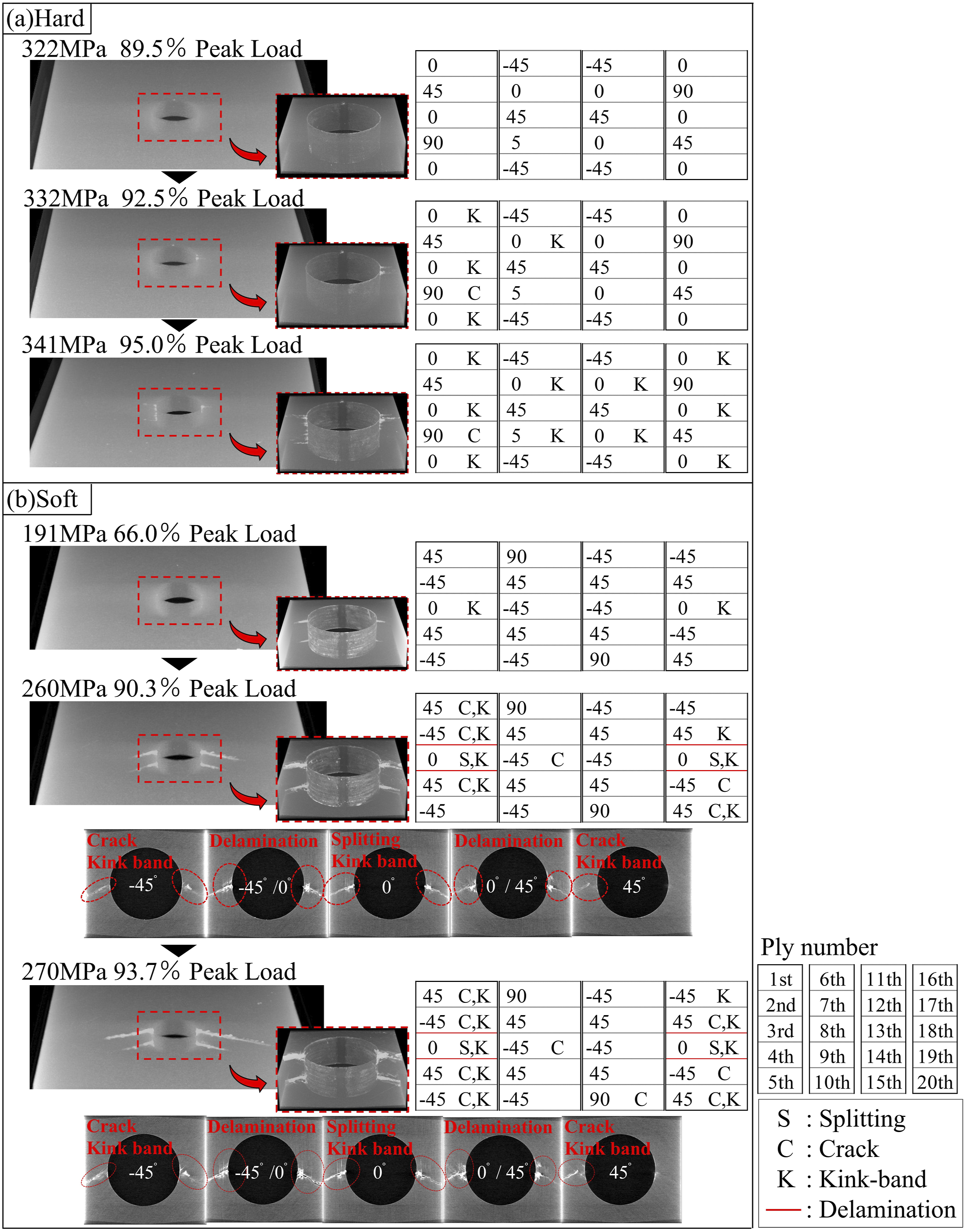
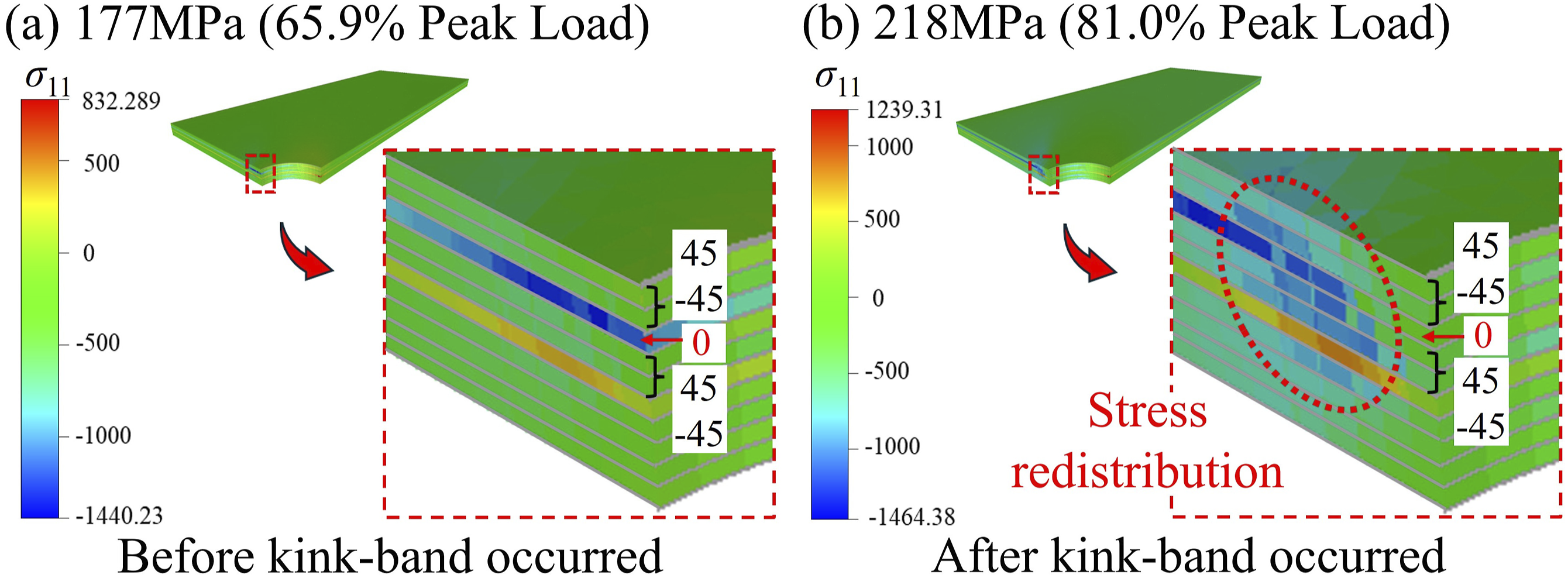
OHC analysis allows detailed observation of damage evolution. This section discusses the formation and propagation of kink-bands predicted by the maximum stress criterion. The damage distribution shown in Figure 6 was obtained from the numerical results. In the hard specimens, kink-bands formed in the 0° layer at 93.4% of the peak load and progressed slightly before final failure occurred. By contrast, in the soft specimens, kink-bands emerged in the 0° layer at 65.0% of the peak load and subsequently propagated at an angle in the width direction, accompanied by minor interlaminar delamination, ultimately leading to failure. These damage distributions and processes showed good agreement with experimental results. A comparison of the stress levels at which kink-bands formed highlights a significant difference: 93.4% of the peak load for hard specimens versus 65.0% for soft specimens. This indicates that kink-band initiation occurs earlier but propagates more slowly in the soft specimens. This difference is attributed to stress redistribution caused by damage in the 0° layer. In hard specimens, the 0° layer dominates the mechanical properties, delaying kink-band formation until higher stress levels are reached. Once kink-bands develop, the stress redistributes to other 0° layers, which also form kink-bands immediately, resulting in final failure. In contrast, Figure 7 shows the stress distributions in soft specimens before and after kink-band formation. After kink-bands form in the 0° layer of the soft specimens, stress redistribution occurs toward the ±45° layers. In these ±45° layers, plastic deformation dissipates energy, suppressing the progression of the kink-bands. Damage distribution from OHC analysis using the maximum stress criterion for (a) hard and (b) soft specimens. Comparison of stress distribution in soft specimens before and after kink-band formation.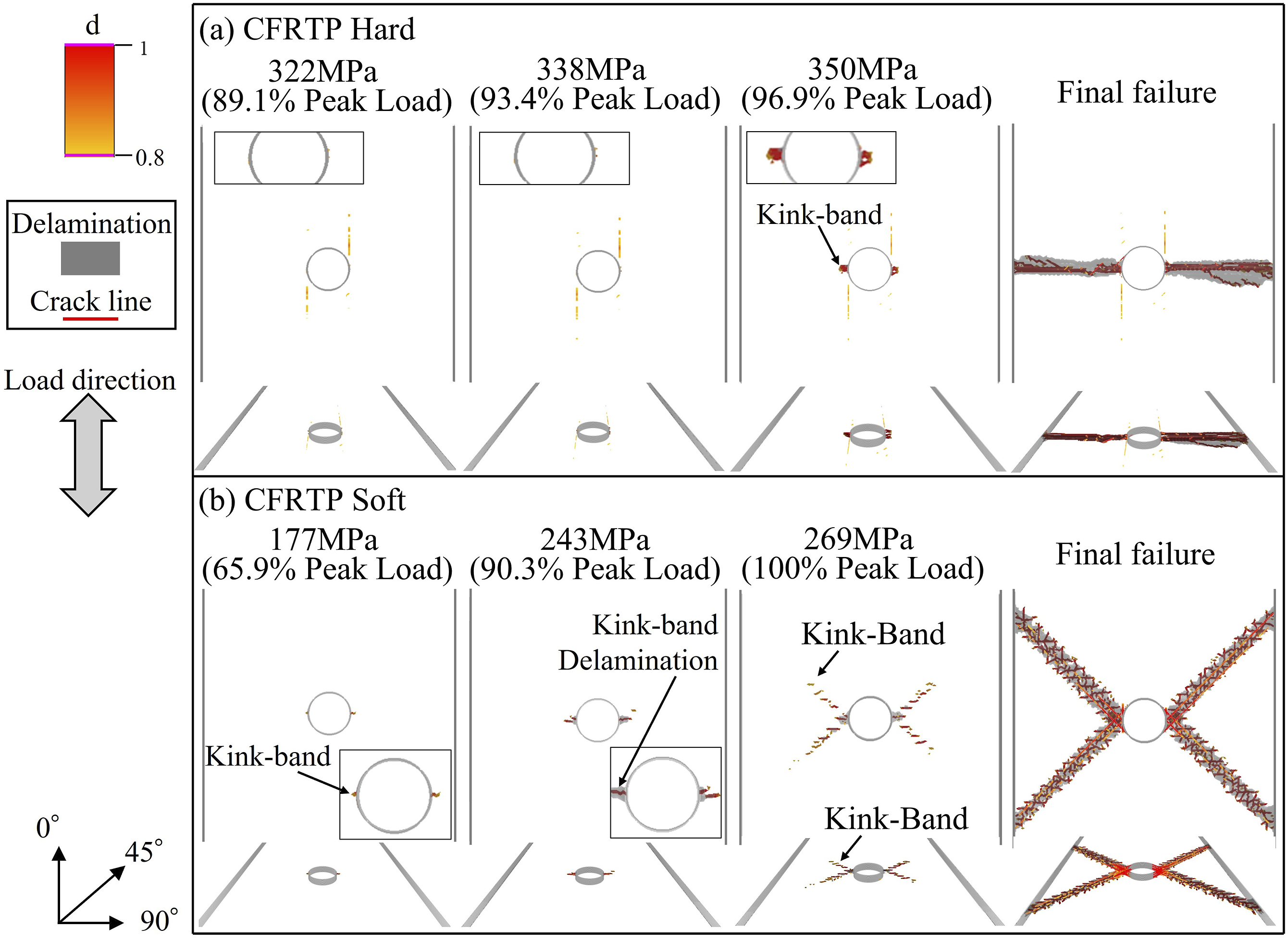
This section provides a comparative analysis of hard and soft specimens in OHC tests. The findings indicated that hard specimens exhibited a brittle stress-strain response in both material types. CFRTS specimens were prone to splitting, leading to immediate failure. In contrast, CFRTP demonstrated resistance to crack growth, and failure occurred after the formation of small kink-bands. These findings suggest that CFRTP provides resistance to compression failure in the fiber direction. For the soft specimens, CFRTS exhibited a relatively linear stress-strain response, while CFRTP displayed nonlinearity due to plastic deformation. In the CFRTS specimens, initial delamination was followed by the formation of a kink-band in the 0° layer, culminating in failure. Conversely, in CFRTP, kink-band formation initiated transverse cracking and delamination along the path of the kink-band. The higher interlaminar properties of CFRTP (tIc = 77.8 MPa, tIIc = 100.4 MPa, GIc = 1.50 N/mm, GIIc = 2.35 N/mm) 34 compared to CFRTS (tIc = 44.3 MPa, tIIc = 86.2 MPa, GIc = 0.227 N/mm, GIIc = 0.788 N/mm)57,75 reduced delamination. As a result, stress was redistributed around the kink-bands, leading to further damage. These failure mechanisms were validated and elucidated through numerical finite element analysis using the maximum stress criterion.
Results and discussion of OHT tests
Stress-strain response and strength evaluation of OHT tests
Figure 8 illustrates the stress-strain responses of hard and soft specimens made from CFRTP and CFRTS, while Table 7 summarizes the test results. In the hard CFRTP specimens, a non-hookean behavior76,77 was observed, characterized by increasing stiffness due to fiber crystalline reorientation. The strength of CFRTP was 39.7% higher than that of CFRTS. This difference aligns with the relationship between the fiber direction tensile strength of the two materials (CFRTP: 3157.9 MPa, CFRTS: 2172 MPa
57
). In the soft CFRTP specimens, plastic deformation of the ±45° plies caused a reduction in stiffness, resulting in a convex-shaped stress-strain response. This behavior could be attributed to the low elastic limit of the CFRTP matrix. Numerical results from the FEM analysis are shown as a red line in Figure 8(a). As discussed in the previous section, the OHT analysis employed the Weibull failure criterion. The results for the hard specimen demonstrated a good agreement between the numerical and experimental stress-strain responses. However, the analysis for the soft specimens resulted in an underestimation of the strength. This discrepancy may be attributed to the fact that the damage state in the vicinity of the open-hole differs from the experimental results. The following section will present a comprehensive analysis of the damage state observed during the OHT test. Experimental and predicted stress-strain curves of the OHT tests for (a) CFRTP and (b) CFRTS. Experimental results of the OHT tests for hard and soft specimens of CFRTP and CFRTS.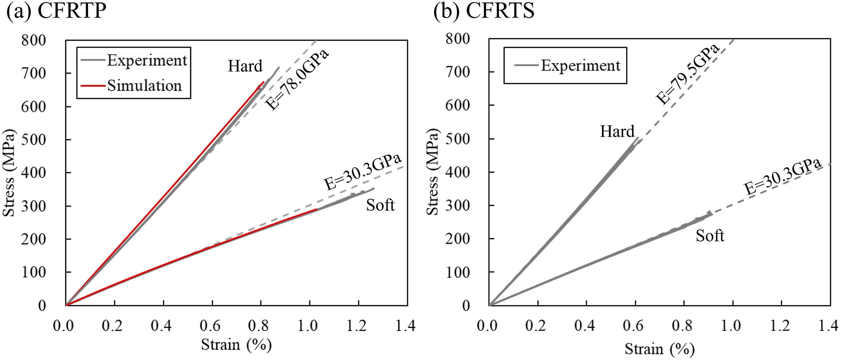
Damage observation in OHT tests
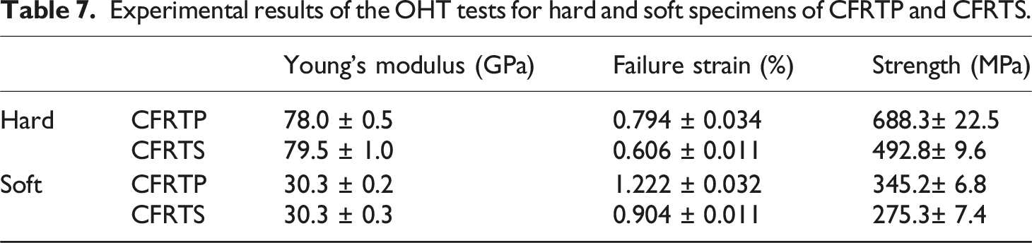
This section discusses the evolution of damage during the OHT test in detail. Figure 9 illustrates the results of in-situ observations during the OHT test. For the hard specimens of both CFRTP and CFRTS (Figure 9(a) and (b)), the first observed damage was splitting cracks in the surface 0° layers. Subsequently, splitting cracks were observed in the inner 0° layer. In the soft specimens of CFRTP (Figure 9(c)), the first observed damage was also a splitting crack in the 0° layer. As the test progressed, delamination occurred. Transverse cracks were also observed in the 90° and 45° layers, ultimately leading to failure. For the soft specimens of CFRTS (Figure 9(d)), the first observed damage was a transverse crack in the surface 45° layer. Due to the limitations of the high-speed digital microscope during in-situ observations, detecting the splitting cracks in the inner 0° layers was challenging. It is, therefore, possible that the initial damage originated in the 0° layers. As the test progressed, delamination and the initiation and propagation of transverse cracks in the 90° and 45° layers were observed, ultimately leading to failure. While comparing the damage occurrence between CFRTP and CFRTS in the hard specimens is challenging, comparing the soft specimens revealed that CFRTP exhibited less matrix-dominated damage. This is due to the higher strength and toughness of the CFRTP matrix, which helped suppress the initiation and progression of damage. In-situ microscope observation results in OHT tests for hard and soft specimens composed of CFRTP and CFRTS.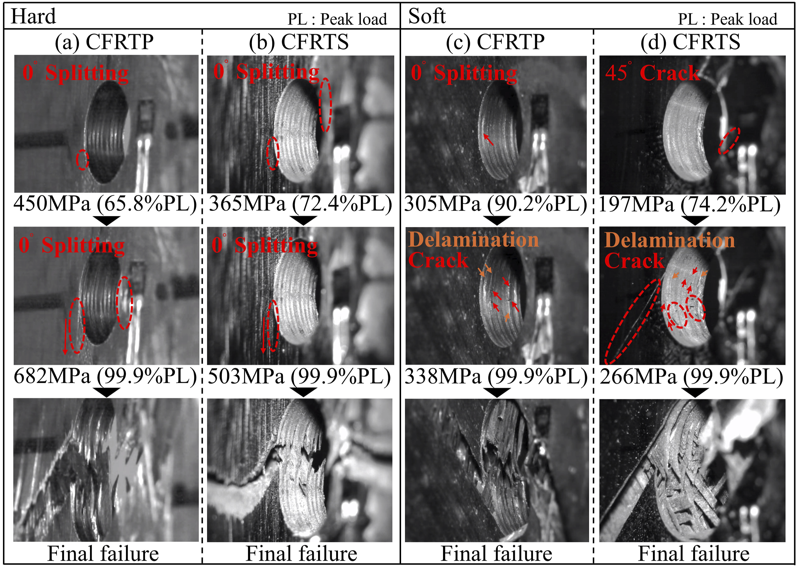
Hallett et al.
17
classified failure modes in OHT tests into three types: brittle, pull-out, and delamination. Figure 10 presents images of the specimens after the OHT test. The OHT specimens used in this study had thin ply thicknesses, resulting in consistent observations of pull-out failure modes. Green et al.
15
reported that delamination failure modes are rare in OHT tests with reduced ply thicknesses, a finding consistent with the results of this study. However, due to the significant difference in fracture toughness values between CFRTP and CFRTS, variations were observed in the hard specimens (Figure 10(a) and (b)). In the CFRTP hard specimen, the fracture surface in the 0° ply propagated from the lower edge of the open-hole at an angle of 45°. In-situ observations revealed no damage in the 0° layer other than splitting cracks, indicating that this fracture surface formed after fiber breakage around the open-hole. This failure mechanism is attributed to stress redistribution to the 45° ply through the interlaminar region following fiber failure in the 0° ply. Crack propagation in the 45° ply, caused by redistributed stress, interacted with the fiber failure in the 0° ply, leading to fracture propagation at a 45° angle from the hole’s lower edge. In the CFRTS hard specimen, the fracture surface propagated perpendicularly to the tensile direction, indicating a more brittle failure mode. This behavior can be attributed to the lower interlaminar fracture toughness of CFRTS. After fiber failure in the 0° ply, the 45° ply lost its load-transfer ability due to immediate delamination and transverse cracking. Consequently, stress redistribution to the 45° ply through the interlaminar region did not occur, causing the crack to propagate exclusively within the 0° ply. For the soft specimens, both CFRTP and CFRTS exhibited similar fracture surfaces. The fracture surface of the 0° ply propagated from the lower edge of the open-hole at a 45° angle, indicating a failure mechanism comparable to that observed in the CFRTP hard specimens. Fracture surfaces of each specimen.
Next, detailed observations from OHT tests using stepwise X-ray imaging and FEM-based damage analysis are compared. Figure 11 presents the stepwise X-ray observations for CFRTP hard and soft specimens, while Figure 12 shows the numerical results obtained using XFEM. As illustrated in Figure 11(a), the hard specimens exhibited initial damage at approximately 64.4% of the peak load, observed as a splitting crack in the surface 0° ply. Subsequent cracking was detected in the inner 0° plies, ±45° plies, and the 90° ply; however, no interlaminar delamination was observed prior to final failure. Notably, the surface 0° ply, which experiences less constraint from adjacent layers, exhibited greater propagation of splitting cracks compared to the internal plies.78,79 The numerical results in Figure 12(a) demonstrate good agreement with the stepwise X-ray observations, accurately capturing damage progression from the initial damage to the maximum load. Stepwise X-ray observation results of CFRTP in the OHT study for the (a) hard and (b) soft specimens. Damage distribution from the OHT analysis for the (a) hard and (b) soft specimens.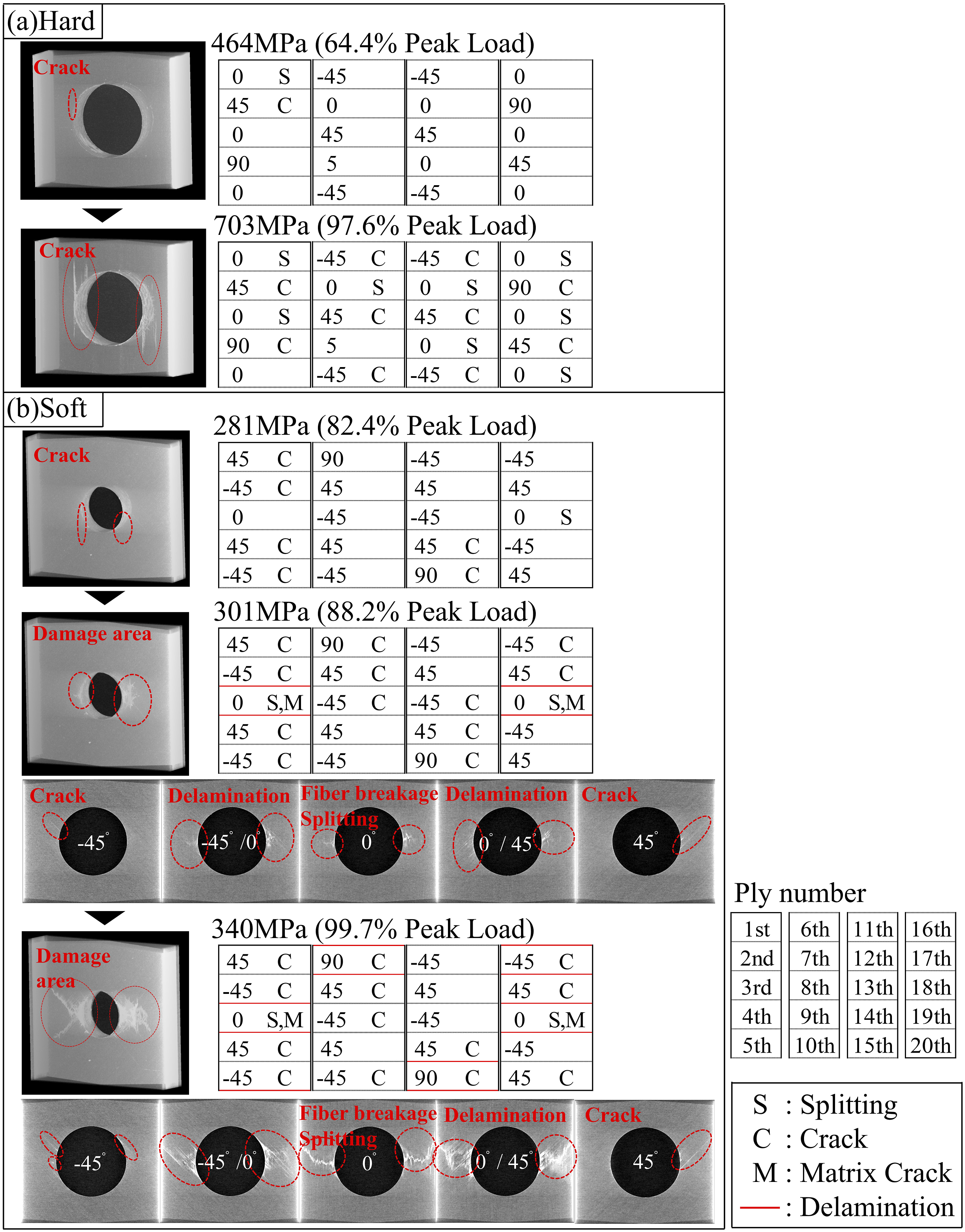
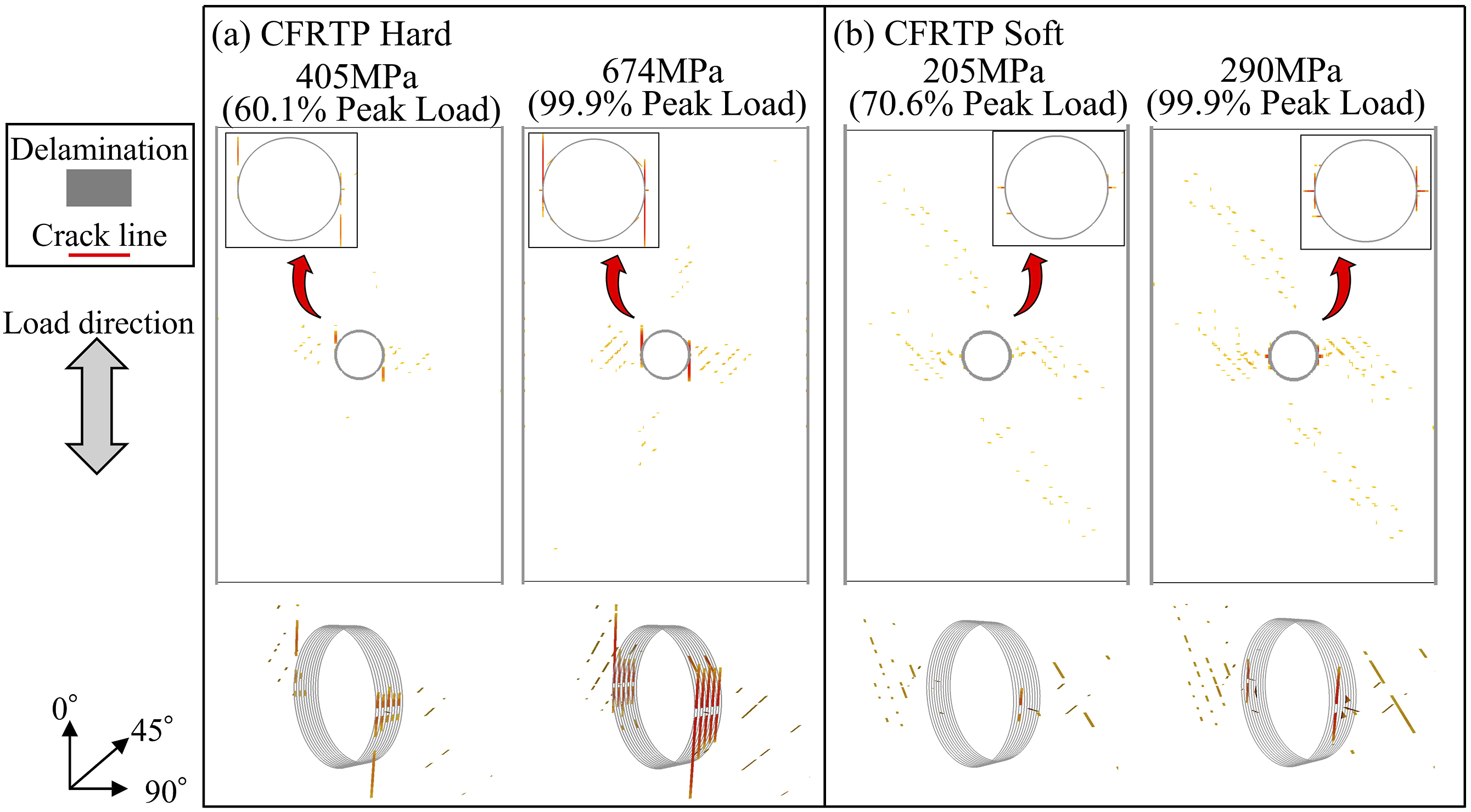
For the soft specimens, initial damage was observed as a splitting crack in the 0° ply, as shown in Figure 11(b). At 281 MPa (82.4% of the peak load), cracks appeared in other layers, although no delamination was detected at this stage. As shown in Figure 12(b), the damage distribution in the numerical analysis at this stage closely matches the results of the stepwise X-ray observations. At 301 MPa (88.2% of the peak load), matrix cracks perpendicular to the fibers propagated in the 0° ply. These damages were likely tensile fractures potentially accompanied by fiber breakage. Delamination and transverse cracking initiated and propagated concurrently with the occurrence of matrix cracks in the 0° ply. However, the FEM analysis failed to reproduce damage progression and delamination after a tensile fracture. This limitation arises because the FEM model assumes that tensile failure propagates instantaneously; once tensile failure occurs in a part of the model, the simulation terminates. Despite this limitation, the predicted strength value of 290.9 MPa from the FEM analysis aligns well with the stress range of 280–300 MPa, where tensile fractures were observed during the stepwise X-ray observations. Therefore, it can be concluded that this numerical approach sufficiently predicts the stress-strain response and damage progression up to the point of tensile fracture. Based on these findings, the following insights were obtained regarding how differences in CFRTP specimens affect failure mechanisms: • Hard specimens: The mechanical properties of hard specimens are dominated by the 0° layers, which prevent tensile failure until high stress levels. Once tensile failure initiates in one 0° layer, stress is redistributed to other 0° layers, resulting in immediate tensile failure in those layers and ultimately leading to catastrophic fracture. • Soft specimens: In contrast, the soft specimens, which contain only two 0° plies, experienced tensile fracture at the hole edge of the 0° ply at relatively low overall stress levels. However, the remaining ±45° plies (16 plies in total) were able to bear the load sufficiently after tensile fracture in the 0° ply. This behavior was evidenced by the rapid crack propagation in the ±45° plies following the tensile fracture of the 0° ply. In the ±45° plies, plastic deformation and crack propagation progressed, leading to energy dissipation. As a result, energy dissipation in the soft specimens was greater than in the hard specimens, suppressing the progression of tensile fractures and preventing instantaneous failure.
The numerical method using the Weibull fracture criterion is effective for scenarios like the hard specimens, where localized tensile fracture immediately leads to overall failure. However, for cases like the CFRTP soft specimens, where localized tensile fracture does not result in immediate failure, the application of this numerical method has limitations.
Detailed observation at NanoTerasu
In the previous section, matrix cracking occurred in the 0° layer of the soft CFRTP specimen, suggesting stable propagation of fiber orthogonal damage. As a final discussion in this paper, further detailed observations of the damage in the 0° layer are carried out to clarify the tensile fracture mechanism of the soft specimens.
Matrix cracks in the 0° layer of the soft specimen were observed using the X-ray micro-CT at the BL10U beamline of NanoTerasu. Prior to observation, the OHT-damaged specimen was cut in the width direction to include the region around the open-hole. Care was taken to ensure that the cut was sufficiently large to prevent new damage in the observation area. The cut section was then polished, reducing the specimen width to approximately 4 mm. The configuration of the prepared specimen is shown in Figure 13. The observed specimen was one for which testing had been interrupted at 306 MPa (88.6% of the average peak load). It is important to note that this specimen differs from the one shown in Figure 11(b). Figure 14(a) presents an image captured using the laboratory X-ray CT, while Figure 14(b)–(d) are images captured using the X-ray micro-CT at NanoTerasu. The images in Figure 14(b)–(d) were obtained by shifting the imaging position to the right three times and reconstructed into a continuous sequence, covering a total length of approximately 4 mm. During the OHT test, damage in the 0° layer of the soft specimens propagated perpendicular to the fibers and was accompanied by fiber breakages and splitting cracks. Most fiber breakages formed clusters, where multiple fibers broke in bundles. These clusters were distributed in a scattered manner within specific regions but, in some areas, extended continuously across the width direction. At the tip of the damaged area, isolated fiber breaks were scattered throughout without forming clusters. CFRTP soft specimen imaged via X-ray micro-CT at NanoTerasu. Damage observation results: (a) laboratory-based X-ray CT, (b)–(d) X-ray micro-CT at NanoTerasu. (b) Image at the hole edge (damage root), (c) image in the middle of the damage site, and (d) image at the damage tip.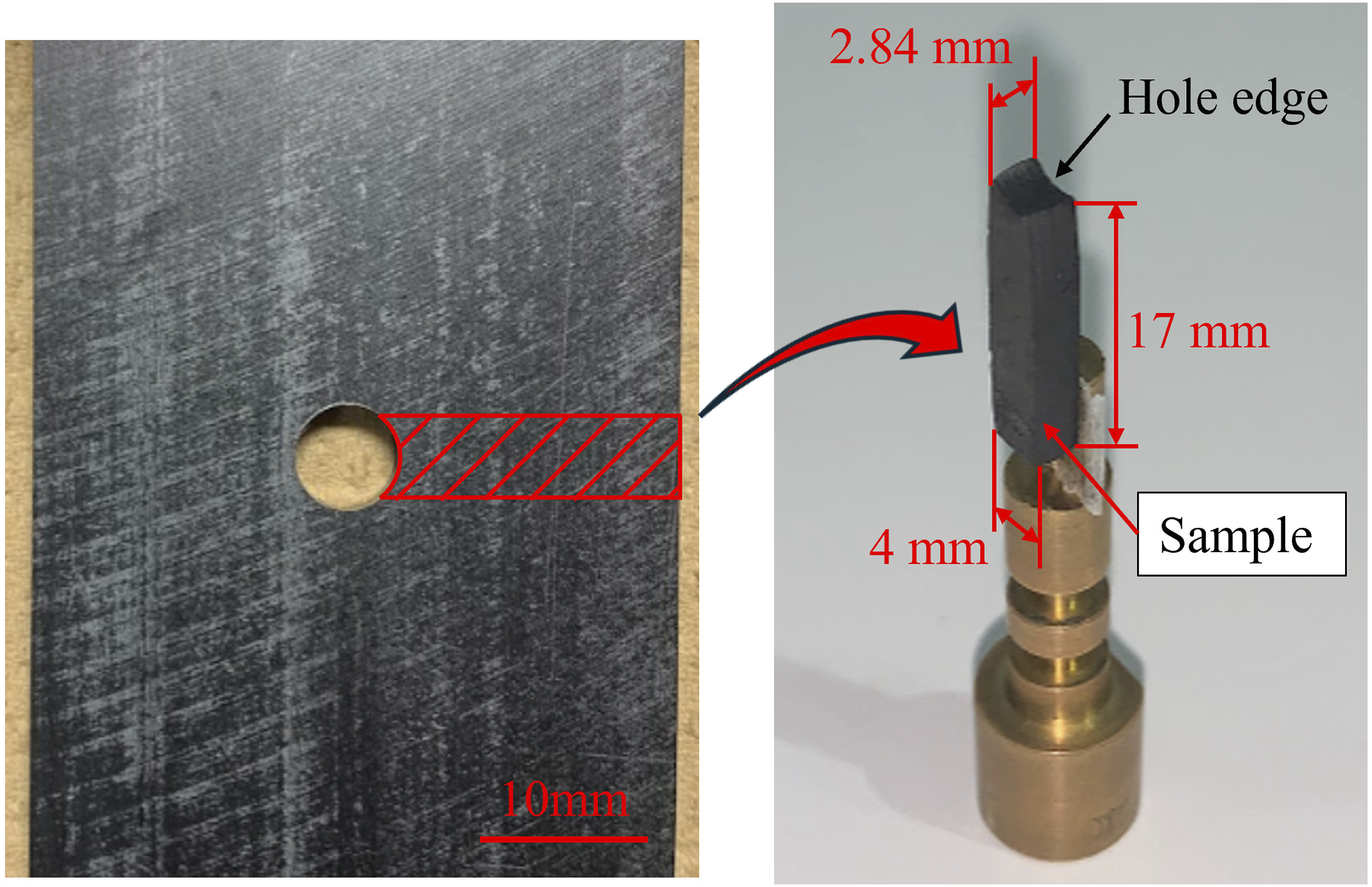
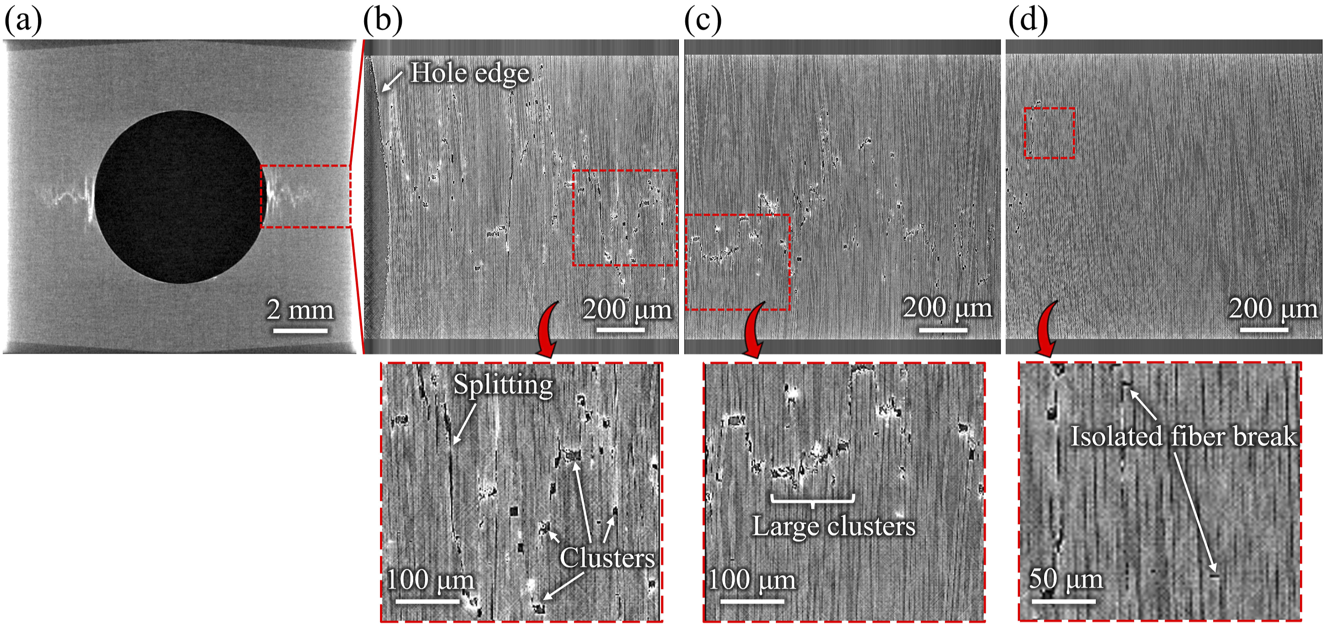
From a macroscopic perspective, as shown in Figure 11(b), damage propagated in the width direction. Microscopically, fiber breakage either accumulated continuously at locations where fibers had already broken or occurred in different areas. The former type of fiber breakage occurs in regions immediately adjacent to the initial break due to the stress concentration, leading to successive breakage at the same location. By contrast, the latter type of fiber breakage is primarily attributed to dynamic stress concentration.80,81 When weaker areas exist in fibers surrounding the initial break but are not present immediately adjacent to it, these fibers may fail in regions slightly removed from the original breakage point. This observation aligns well with previous studies.82,83 Splitting cracks occurred between the scattered fiber breaks, suggesting that fiber breakage first occurred in a dispersed manner, followed by the formation of splitting cracks between these breaks. The mechanism by which splitting cracks developed between broken fibers can be explained as follows: fibers that broke transmitted load through the matrix resin via shear stress. When adjacent fibers also broke, the matrix between the broken fibers experienced increased shear forces under tensile loading, leading to the generation of splitting cracks.
Observations using X-ray micro-CT revealed that fiber-orthogonal damage in the 0° layer progresses stably in OHT soft specimens. This stable damage propagation reduces stress concentration around the open-hole and increases the ultimate strength. Therefore, the damage evolution observed in this section explains why the Weibull criterion underestimated the strength of the soft specimens in the OHT analysis. It also clarifies why CFRTP exhibited higher strength than CFRTS. The higher fracture toughness of the thermoplastic resin compared to the thermosetting resin inhibits matrix-crack propagation, leading to a delay in the expansion of fiber fracture clusters caused by the stress concentration at the matrix crack tip. These properties slow the propagation of damage in the width direction and enhance the OHT strength of the soft specimens.
Conclusion
In this study, the effect of stacking sequences on CFRTP laminates with holes was investigated through a combination of experimental and numerical approaches. Experimentally, in-situ observations were conducted using a high-speed digital microscope, stepwise X-ray imaging was performed with a laboratory X-ray CT, and damage progression in soft specimens subjected to interrupted OHT tests was analyzed using X-ray micro-CT at NanoTerasu. These methods provided detailed insights into the mechanisms of damage progression. In the numerical analysis, XFEM simulations were conducted, considering the material nonlinearity. The maximum stress criterion and SCM for fiber direction failure were used to predict OHC strength, and the Weibull failure criterion was used to predict OHT strength. The following findings were obtained in this study. • In the OHC tests, the strength of the hard specimens was lower than that of CFRTS due to the lower compressive strength of CFRTP in the fiber direction. In contrast, the strength of the soft specimens was comparable to that of CFRTS because kink-band propagation was suppressed by energy dissipation through plastic deformation, which was more pronounced in CFRTP. In the CFRTS specimens, initial delamination was followed by the formation of a kink-band in the 0° layer, ultimately leading to failure. Conversely, in CFRTP, kink-band formation initiated transverse cracking and delamination along the path of the kink-band. This difference is attributed to the higher interlaminar properties of CFRTP. These failure mechanisms were validated through numerical finite element analysis and explained using the maximum stress criterion. • The strength in the OHT tests was higher for CFRTP than for CFRTS in both stacking sequences. Once tensile failure initiated in the 0° layer of the hard specimens, it propagated rapidly, leading to the failure of the entire specimen. In contrast, energy dissipation in the soft specimens inhibited the progression of tensile fracture, preventing instantaneous failure. The strength prediction using the Weibull failure criterion was accurate for the hard specimens but underestimated the strength of the soft specimens, which results from the gradual progression of tensile fracture, as observed in the soft specimens. • Observation of the area around the hole in the soft specimen during the OHT test via X-ray micro-CT at NanoTerasu showed that the gradual damage progression involved fiber breakage and the formation of splitting cracks. The high fracture toughness of thermoplastics inhibits matrix crack propagation and delays the expansion of fiber fracture clusters. The OHT strength of CFRTP was increased due to the above mechanisms.
The results of this study have clarified the fracture mechanisms in the OHT and OHC tests of CFRTP laminates and provided essential guidelines for developing methods to predict the OHT and OHC strengths of CFRTP. As a future issue for consideration, it is necessary to review the modeling of the 0° layer fracture in the OHT strength. For the soft specimen, it is necessary to introduce fiber direction damage and model the points where immediate and gradual 0° layer failure differs depending on the stacking sequences of laminates. For the OHC strength, the modeling in this study could not account for the micro-buckling of the fibers. It has been suggested that the initial irregular angle of the fibers in CFRTP increases during the molding process, and it is a challenge to model the initial irregular angle and kink-band formation.
Footnotes
Acknowledgements
We would like to express our gratitude to all the members of QST NanoTerasu Center and PhoSIC for their support in utilizing NanoTerasu.
Declaration of Conflicting Interests
The author(s) declared no potential conflicts of interest with respect to the research, authorship, and/or publication of this article.
Funding
The author(s) disclosed receipt of the following financial support for the research, authorship, and/or publication of this article: This work was supported by JSPS KAKENHI Grant Number JP24K17167. This work was based on results obtained from a project, JPNP20010, subsidized by the New Energy and Industrial Technology Development Organization (NEDO).
Appendix
Figure 15 depicts the longitudinal damage distribution in the soft specimen obtained from the open-hole compression (OHC) analysis using the LaRC03 criterion for kink-band formation. Kink-bands were observed to initiate at approximately 180 MPa in both the 0° and ±45° layers. With increased strain, multiple kink-bands appeared in the ±45° layers, forming an X-shaped pattern around the open-hole. As the strain increased, multiple kink-bands developed in the −45° and 0° layers. In this analysis, the damage in the 0° and ±45° layers exhibited a rapid progression starting from approximately 200 MPa, resulting in an overestimation of damage compared to the experimental results. This stress level aligns with the sharp increase in nonlinearity observed in the LaRC03-based analysis, as depicted in Figure 3(a). Consequently, the discrepancy between the numerical results based on the LaRC03 failure criteria and the experimental data is attributed to the overestimation of damage and the associated energy dissipation. Damage distribution from the OHC analysis using the LaRC03 failure criterion for the soft CFRTP specimen.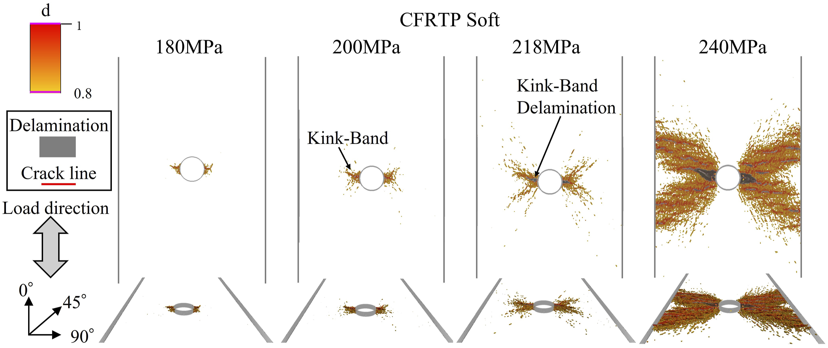
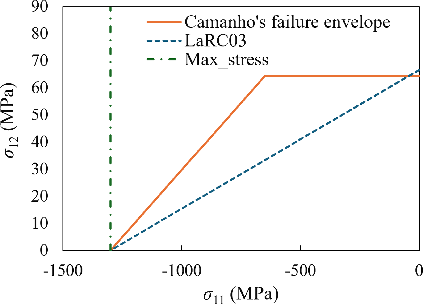
Next, we discuss the reasons behind the overestimation of damage according to the LaRC03 failure criterion. Figure 16 presents a comparison of the LaRC03 failure criteria and the criteria proposed by Camanho et al.
74
in the σ11 − σ12 space. It is inferred that the overestimation of damage in the LaRC03 failure criteria is attributable to shear stress. According to the LaRC03 failure criteria, when a component experiences shear stress close to its shear strength, it is deemed to be in a state of failure if there is any slight compressive stress acting on that component. In contrast, Camanho et al.
74
assert that failure does not occur even if shear stress reaches shear strength, provided that the compressive stress remains below a certain threshold. The soft specimens are characterized by shear-dominated behavior, making them susceptible to failure due to the combination of high shear stress and low compressive stress, particularly in the ±45° layers. Furthermore, interlaminar delamination is less likely to occur in CFRTP, allowing for an easier redistribution of stress to the ±45° layers following the failure of the 0° layer. As a result, the shear stress increases, further facilitating damage in the ±45° layers. This overestimation of damage in the ±45° layers is believed to contribute to the discrepancies observed between the experimental results and the numerical predictions. Comparison of failure envelopes for the maximum stress criterion, LaRC03 criterion, and Camanho’s failure envelopes.