
Abstract
The mechanical recycling process of fiber-reinforced composite parts involves shredding long continuous fibers into shorter discontinuous fibers. Since the performance of the shredded short fibers is not as high as that of the original long fibers, the application of recycled composites is limited. The objective of this study is to enhance the structural performance of recycled composite parts by integrating of a set of continuous fiber composite precuts during the molding process. The 2-dimentional precuts were positioned in the structurally critical regions of the recycled composite part, and the remaining area was then filled with shredded composite material. An aircraft overhead bin door pin bracket was used as the part geometry. The mechanically recycled material and the precuts were made from 60% by weight carbon fiber reinforced polyetherketoneketone (PEKK) composite. Three different combinations of precuts were designed to create the pin bracket, and their performance was assessed by mechanical testing of the pin bracket. Additionally, digital image correlation (DIC) technology was used to analyze local strain changes and investigate the failure mechanisms of the parts throughout the testing process. The test results demonstrated that the inclusion of properly designed precuts significantly improved the performance of the recycled composite part.
Introduction
The fiber-reinforced composite materials have widely used across various industries such as aerospace, aviation, automotive, wind energy, construction, and sporting goods. The advanced composite materials offer advantageous mechanical and physical properties, including high strength-to-weight ratio, stiffness, and low coefficient of thermal expansion (CTE).1–3 As a result, their demand has been steadily increasing, with projections indicating substantial growth in the global composites market.4–7 However, along with the increased usage of composite materials comes the challenge of addressing their sustainability throughout their lifecycle.8–10 The management of end-of-life (EOL) composite parts has been a significant concern, as their disposal through traditional methods like landfilling has not only ineffective in terms of sustainability but also severe damage to environment.8,11–13 To address this issue, many regulations related to EOL composites were implemented to encourage recycling or promote alternative waste management practices for composites.9,14
Composite recycling methods generally fall into three categories: mechanical, pyrolysis, and chemical recycling.15–17 Both pyrolysis and chemical recycling methods offer the advantage of extracting long continuous fibers from end-of-life (EOL) composite parts. However, they come with the drawback of being intricate and expensive processes.16,17 Mechanical recycling is one of the most commonly used methods due to its simplicity and cost-effectiveness.11,18,19 Composite mechanical recycling includes shredding and grinding the composite material to reduce it into smaller fragments.9,18,20 These shredded recycled composite materials are reused in new composite product or reinforcement additives. However, the mechanical recycling process may result in a reduction in the performance of the recycled composite compared to the original composite.9,20–23 Previous studies have reported that mechanically recycled composites showed a reduction in fiber length with each recycling iteration, resulting in a subsequent degradation of their mechanical properties.22,23 Therefore, the applications of mechanically recycled composites are often limited.9,20 It is important to find a way to enhance the performance of recycled composite parts and broaden the application range of them to enhance the sustainability and to promote the recycling of composite materials.
Several literatures have been introduced to enhance the performance of parts made with short fibers.24–30 One common example is hybrid long and short fiber composite overmolding, a technique that involves molding both long and short fibers together within the part.25–29,31 Typically, long fibers are positioned in structurally critical areas, while the remaining sections or complicated geometric portions are filled with short fibers, resulting in structurally enhanced parts with complex geometries.31–35 Conventional hybrid overmolding processes typically involve the use of continuous fibers in ply form, primarily suited for reinforcing long fibers in relatively simpler geometries.27,31,35 Barocio et al. 36 presented an innovative approach to the hybrid long and short fiber composite overmolding process, using a 3D printed continuous fiber-reinforced composite preform. The application of 3D printing technology allows for higher design flexibility in the positioning of continuous fibers within the part. They fabricated pin brackets with thermoplastic short fiber composite platelet and the 3D printed preform. They reported that embedding just 16% by weight of 3D printed continuous fiber. Reported a 60% improvement in structural performance. 36 Kim et al. 37 enhanced the structural performance of recycled composite parts by incorporating 3D printed continuous fiber composites into parts made from mechanically recycled composite material. Despite the 3D printed continuous fiber composite accounting for only about 17% of the total weight of the part, an approximately 61% increase in maximum load was reported compared to recycled composite parts without the preform. 37 Also, when compared to pin brackets made from pristine long discontinuous fiber platelets, the pin brackets made from recycled composites embedded with 3D printed continuous fiber preform showed around a 17% higher maximum load. 37 This demonstrated that incorporating a 3D printed preform not only facilitated recycling but also produced parts with superior performance compared to those made from pristine materials, representing an upcycling process.
This study demonstrated an innovative approach to enhance the mechanical performance of recycled composite parts through the integration of two-dimensional continuous fiber composite precuts. These precuts are fabricated by cutting them from composite laminates. They are selectively placed in structurally critical areas to reinforce the parts and provide additional strength in mechanically demanding sections. A key difference of approach of this study from traditional overmolding lies in the utilization of consolidated laminates rather than pristine or new continuous fiber composite plies.33,34 This approach enables the use of continuous fiber composite laminates, from which the precuts are obtained, that can even be sourced from End-of-Life (EOL) composite parts. Rather than shredding all composite parts in the composite recycling process, the suitable composite parts can be used for precut fabrication. To implement this approach successfully, careful planning and consideration are required regarding precut design and how they will be cut from the parts. Not all composite parts have a two-dimensional flat geometry. Additional processes, such as composite part flattening, may be necessary before the precut fabrication. However, by utilizing EOL composite parts to create precuts, the need for additional new continuous fiber composite materials can be eliminated. This approach represents a closed sustainability loop, where materials can be continually recycled and repurposed without the introduction of new resources as shown in Figure 1. Closed composite material sustainability loop via continuous fiber precut integration approach.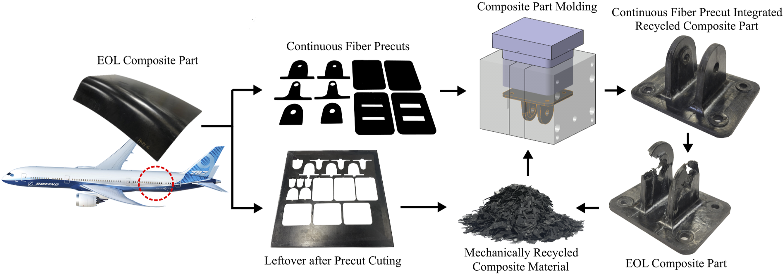
In this study, recycled composite parts were manufactured using mechanically recycled composite material. The load-critical areas were identified, and the precuts were specifically designed to reinforce those regions. Sets of precuts with different designs were fabricated and integrated into the recycled composite parts during the molding process. The mechanical performance of the recycled composite parts with precuts was then tested to assess how different precut designs improved their structural performance, and these results were compared to the performance of recycled composite parts without precuts. With the novel recycling approach, this study aims to contribute to the enhancement of sustainability by effectively utilizing EOL composite part and recycled composite materials, thereby creating additional applications and improving overall sustainability of the composite materials.
Methodology
An aircraft overhead bin door pin bracket was selected as a part geometry for this study. The pin bracket plays an essential role in providing strength and ensuring safety while maintaining a lightweight design. Furthermore, the manageable size of the pin bracket facilitated the production of multiple samples for testing purposes. The pin bracket consisted of two ears which have holes for pin insertion. The ears had an approximate height of 30.48 mm, with varying thicknesses. The thicker section measured approximately 5.08 mm. These ears were connected to a base with dimensions of around 63.40 mm by 50.70 mm and a thickness of approximately 2.54 mm. The base has four screw holes to which screws are fastened to install the pin bracket. Figure 2 shows the pin bracket design. Aircraft overhead bin door pin bracket design.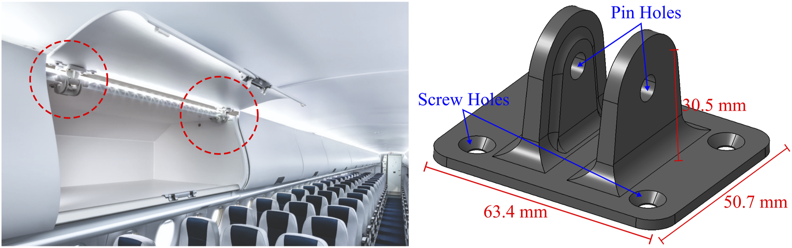
First, the continuous fiber precuts that was integrated into the pin bracket needed to be designed. The strategic design of the precuts was crucial to optimize the load distribution and maximize the structural performance of the part. The previous testing on carbon fiber-reinforced thermoplastic composite sheet molding compound (SMC) pin brackets showed that failures occurred in the ear and base regions.36,37 In the ear section of the pin bracket, particularly in the areas above the pin hole and in the center where the load was applied was failed. During the compression molding process of manufacturing pin brackets using SMC, the material flow resulted in the formation of welding lines at the ear above the pin hole. Welding lines occur when the molten material flows around obstacles or merges with other material flow fronts, resulting in a line that can weaken the structural integrity of the pin bracket.36,37 In the base section, the failures occurred in the areas where screws were installed. This is due to the localized stress formation around the screw holes when the screws are installed and subjected to loading.36,37
To address this issue, it was essential to reinforce the ear section, specifically the upper portion above the pin hole, with continuous fiber. The precut had an ear-shaped with a pin hole, allowing for the simultaneous molding with the pin during the manufacturing process was designed. This design approach eliminated potential welding lines and enabled the precise placement of continuous fiber around the pin hole area. To improve the performance of the base section, a continuous fiber precut of the same size as the base was integrated into the design. The base design aimed to reinforce the base and distribute the load more evenly, reducing stress concentration and the risk of failure in the screw-fastened areas Figure 3(a) shows the precut design set 1. In the primitive experiment, the pin bracket with the precut design one was mechanically tested. The test result showed that the pin bracket no longer experienced failure at the ears or the base. However, it failed at the area where the ears were connected to the base. The test result addressed the need to develop a precut design that would effectively connect the ears and base sections with continuous fiber. The new precut design was developed to have slots in the base and allowed the ear to pass through the slot. The ear precuts had a wider section on the bottom that enabled the ear to withstand the pulling load without simply slipping through the slot. This precut design concept is similar to three-dimensional puzzle, where the components interlock and provide structural integrity. Figure 3(b) shows the precut design set 2. As a final iteration of the precut design, additional layers of precuts were added each ear, while the basic design of the ear and base were same as the previous three-dimensional puzzle design. This designed aimed to enhance the load-carrying capacity by increasing the amount of continuous fiber within the pin bracket. Through these design refinements, the study aimed to achieve a more robust and effective precuts design that would contribute to the overall improvement of the recycled composite part’s mechanical performance. Figure 3(c) shows the precut design set 3. Precut set and assembled precut image for (a) the precut design 1, (b) the precut design 2, and (c) the precut design 3.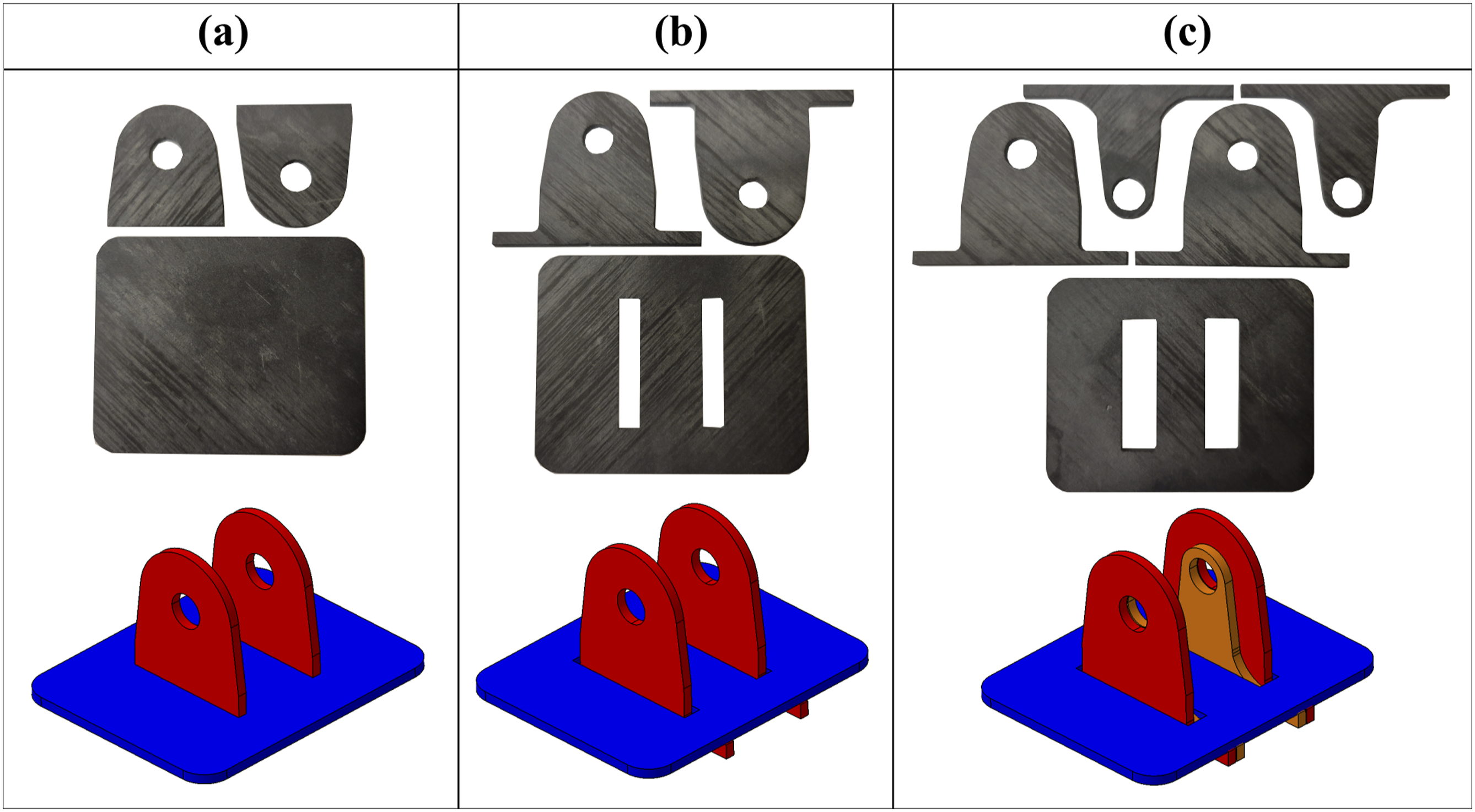
For both precut and mechanically recycled material, a unidirectional tape consisting of 60% by volume AS4D carbon fiber-reinforced Polyether-Ketone-Ketone (PEKK), produced by Solvay, was used. The precut was fabricated from a 20-ply quasi-isotropic laminate, approximately 2.54 mm thick, with a fiber orientation of [45/90/-45/0/90/0/0/45/90/-45]s. The precuts were cut from the laminate using an abrasive waterjet. After cutting, the surface of the precuts was lightly sandblasted to remove any remaining release agents or grease and to enhance bonding with the recycled material. The precut design set one weighed 16.67 g, set two weighed 19.37 g, and set three weighed 22.17 g. The recycled material was shredded from the continuous fiber laminate using Wanner “The Baby Series” granulator, and the resulting shredded material was predominantly in the form of chips or flakes. The average fiber length of the shredded material was 4.7 mm. To measure the fiber lengths, the shredded material was thermally decomposed in a furnace to remove the polymer matrix, and the remaining fibers were analyzed microscopically. The fiber diameter of AS4D was 6.7 µm, resulting in an average aspect ratio of approximately 700. Figure 4(a) shows the shredded recycled composite material and its fiber length distribution. (a) Mechanically recycled CF-PEKK material and its fiber length distribution. (b) Compression-molded recycled CF-PEKK plate and the test specimen layout. (c) Ultimate tensile strength of the recycled material (x- and y-directions) compared to continuous 0° and 90° laminates. (d) Tensile modulus of the recycled material (x- and y-directions), continuous 0° and 90° laminates, and the predicted modulus of the quasi-isotropic laminate used in this study.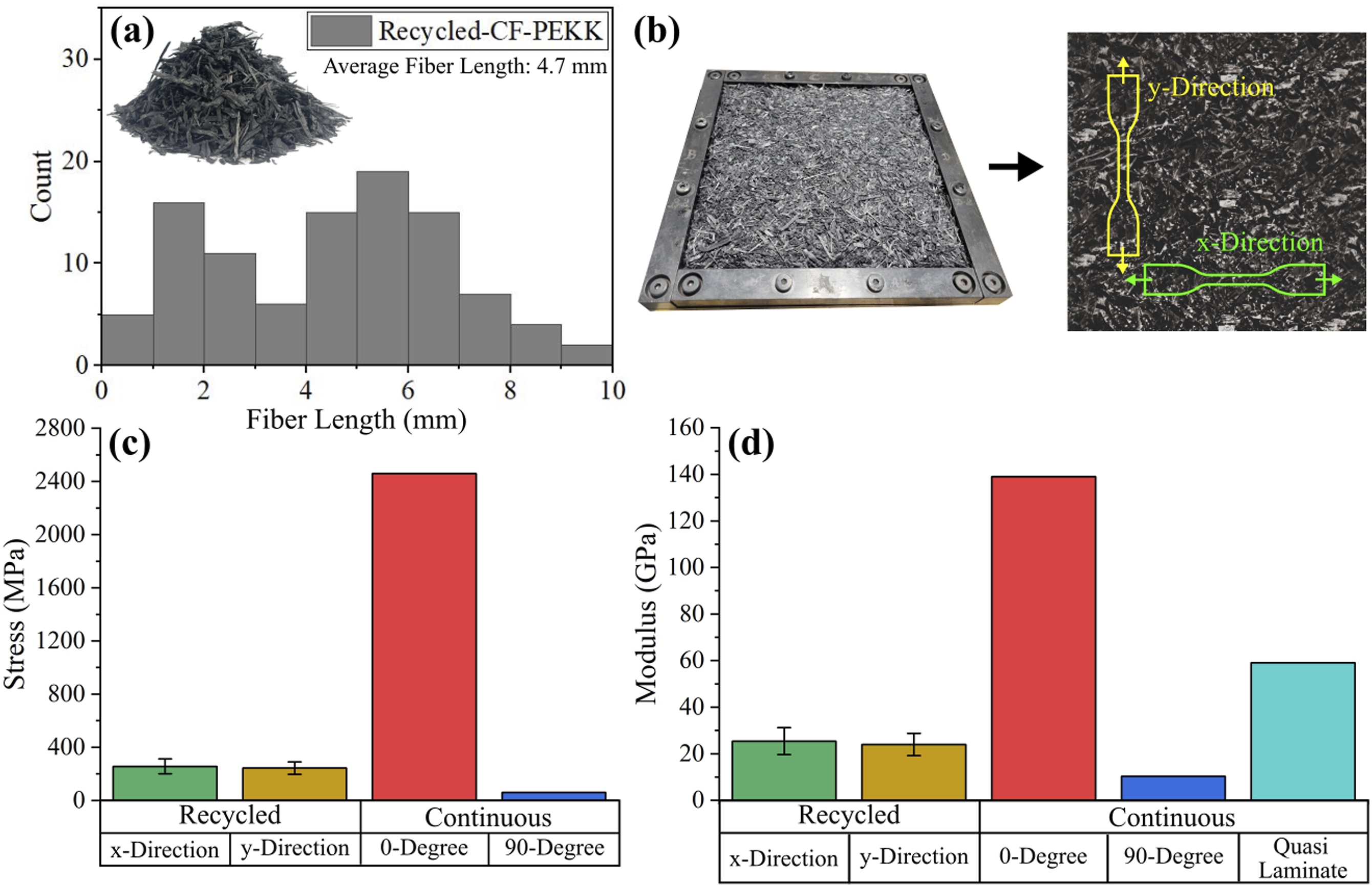
To evaluate the mechanical properties of the recycled shredded material, the recyclates were compression molded into flat plate, as shown in Figure 4(b). Tensile test specimens were cut from the molded laminate and tested in two orthogonal directions. The results showed that the first direction (x-direction) had an average tensile strength of 256 MPa and a modulus of 25.4 GPa, while the second direction (y-direction) had an average tensile strength of 244 MPa and a modulus of 24.0 GPa. These results did not show a significant difference in tensile properties between the two orthogonal directions of the recycled material. According to the technical data sheet provided by the material manufacturer, the 0° continuous fiber composite has a tensile strength of 2460 MPa and a tensile modulus of 139 GPa, while the 90° continuous fiber composite has a tensile strength of 61 MPa and a tensile modulus of 10.3 GPa. The predicted modulus of the 20-ply quasi-isotropic laminate, calculated using Classical Laminate Plate Theory (CLPT), was approximately 59 GPa. Figure 4(c) and 4(d) show bar graphs of the ultimate tensile strength and tensile modulus of the molded recycled material laminate, the continuous fiber-reinforced composites in 0° and 90° directions, and the predicted modulus for the quasi-isotropic laminate.
A compression molding tool made from H13 tool steel was used to fabricate the pin bracket geometry. The exploded view of the compression molding tool shown in Figure 5 provides an overview of the different sections of the tool and the inserts used to mold the pin hole and the screw holes at the base of the bracket. The tool is equipped with a thermocouple well to record temperature during manufacturing. Compression molding tool used to fabricate the pin bracket.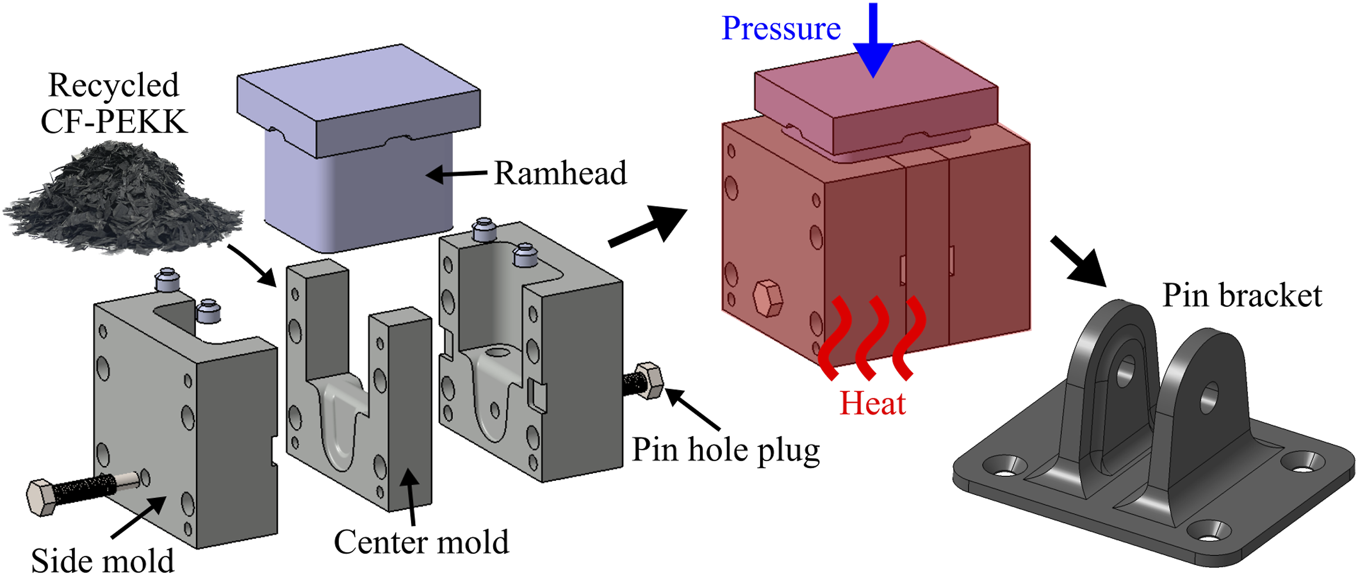
Each precut design had a unique method for installation. For the first precut design, the ear precuts could be easily installed to the tool during the tool assembly process as shown in Figure 6(a). Then, the recycled material was poured into the tool, and the base precut was placed on the top of the recycled material as shown in Figure 6(b). The second and third precut designs had more challenges since the ear and base precut were interlocked, prohibiting separate installation. Therefore, the ear and base precuts were assembled together and integrated into the tool while the tools were assembled as shown in Figure 6(c) (precut design 2). Then, the recycled material was poured into the tool. To ensure that there was an enough material to fill the ear cavities fully, some recycled material was pushed into the ear cavities through the slots on the base precut while the recycled material was poured as shown in Figure 6(d). All pin brackets were fabricated with the same amount of composite material. The total amount of composite material including both continuous fiber precuts and the recycled material in the pin bracket were 31.4 g. Manufacturing of the pin bracket including continuous fiber precuts. (a) The placement of the ear precut of the precut design one and (b) the placement of the base precut of the precut design 1. (c) The placement of the assembled ear and base precuts into the tool while the tools were assembled, and (d) the tool cavity filled with the recycled materials.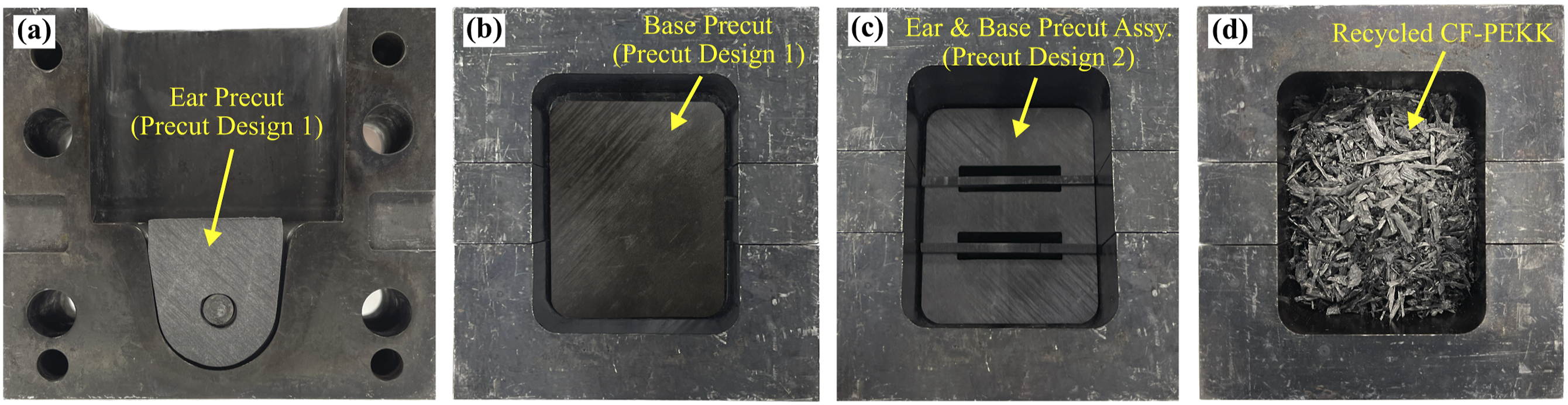
Process conditions for compression molding. 36
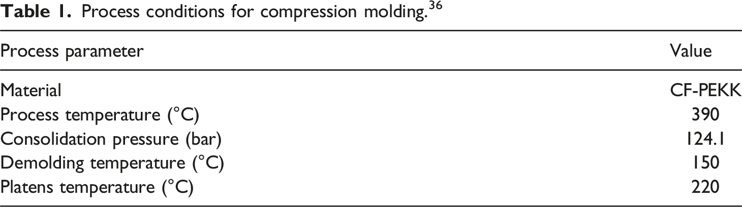
Quasistatic tests of the pin brackets were conducted with a universal test machine MTS 810 equipped with a 100 kN load cell. A displacement control procedure was carried out at a rate of 2 mm/min until the ultimate failure of the bracket was reached. A custom-made fixture was utilized to load the pin bracket in tension as shown in Figure 7(a). The pin bracket was installed on the test fixture with four 10-32 screws torqued to 40.67 Nm. Digital Image Correlation (DIC) was used to record the strain field developed at the surface of the pin bracket’s ear during loading. Figure 7(b) shows the strain field in the load direction developed before and after ultimate failure of a pin bracket reinforced with continuous fibers. Three pin brackets for each precut design and four pin brackets with only recycled material for the baseline were tested. (a) Mechanical testing setup for the pin brackets.
36
(b) Strain field in the load direction obtained from DIC analysis before and after failure in the pin bracket.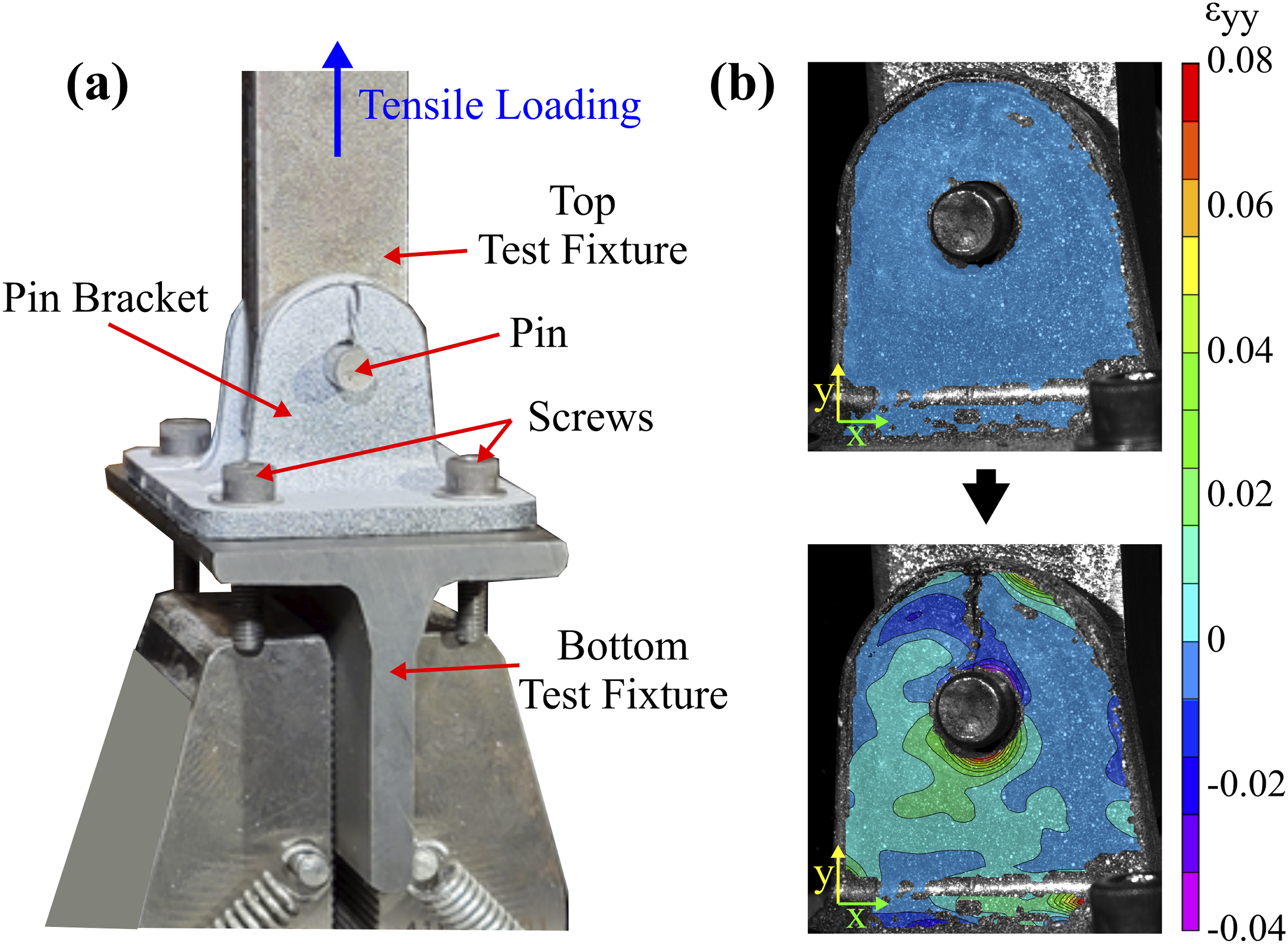
Results
The pin brackets with three different precut designs and the pin brackets without precuts, only with the recycled composite material, were successfully fabricated. Three pin brackets were manufactured for each precut design, and four pin brackets were fabricated without any precut, making a total of 13 pin brackets. There was no evidence of any defects such as void or crack on the surface of the pin brackets. After manufacturing the pin brackets, the pin holes on the ears and screw holes on the base were finished with drills, as well as sanding to remove any burrs. To observe the fiber distribution within the molded pin brackets and to observe any defects, such as void, inside of the pin brackets, microscopic image of the cross-section of the pin bracket with different precut were made as shown in Figure 8. The microscopic images demonstrated that the fibers were effectively placed along the boundaries of the ear and pin hole sections. Similarly, in the base sections, the fibers adequately covered the screw holes. For the precut design 1, it was found that the ear precut were pushed inside of the ear cavity and it made a noticeable continuous fiber gap between the ear precut and base precut. The gap between the precuts was filled with the recycled composite materials. In the precut design 2 & 3, the ear precut held its position during the forming process. The continuous fiber was observed across of entire ear, and the wider bottom section of the ear preform positioned properly underneath of the base precut. For all the precut designs, it was found that the fiber orientation of the ear precut laminate (quasi-isotropic) was not maintained during the forming process, resulting many wavy fiber orientations and buckling were observed in the precut. The base precut relatively remained same location where it was installed during the precut placement process. No defects were observed on the cross-sectional area of the pin bracket in the microscopic image. The microscopic image of cross-sectional area of the pin brackets fabricated with the precut design 1 and 2 & 3.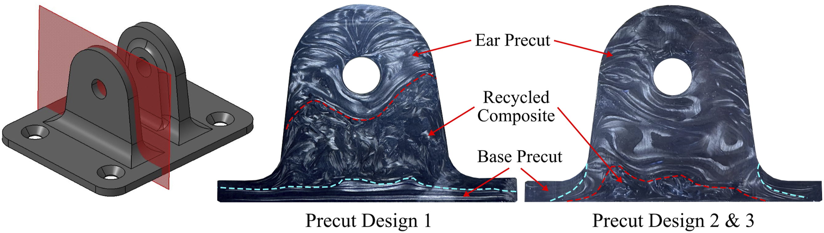
The mechanical test results, showing load versus displacement for each pin bracket, are depicted in Figure 9. The maximum load, onset failure load, and displacement at failure for each pin bracket with different precut designs were compared. The maximum load represents the highest load experienced by the pin bracket during the test. While some pin brackets reached the maximum load and failed immediately, others demonstrated a gradual decrease in load due to crack propagation before experiencing complete failure. Figure 10 shows bar graphs of the average maximum load, onset failure load, and displacement at failure for pin brackets fabricated without precut, with precut designs 1, 2, and 3. The pin brackets without any precut, that is only made with the recycled material, had an average maximum load of 10.5 kN. The pin brackets fabricated with precut design one had an average maximum load of 12.8 kN, which is 22% higher than the average maximum load of pin brackets fabricated only with the recycled material. The pin brackets with the precut design two had an average maximum load of 13.6 kN, which is 30% higher than the average maximum load of the recycled pin brackets. The pin brackets fabricated with precut design three had an average maximum load of 14.1 kN, which is 34% higher than the average maximum load of the recycled pin brackets without the precuts. Load-displacement plot during the mechanical testing of the pin bracket (a) without precut, (b) with the precut design 1, (c) with the precut design 2, and (d) with the precut design 3. Average (a) maximum load, (b) onset failure load, and (c) displacement at failure of the pin brackets fabricated without precut and with the precut design 1, 2, and 3.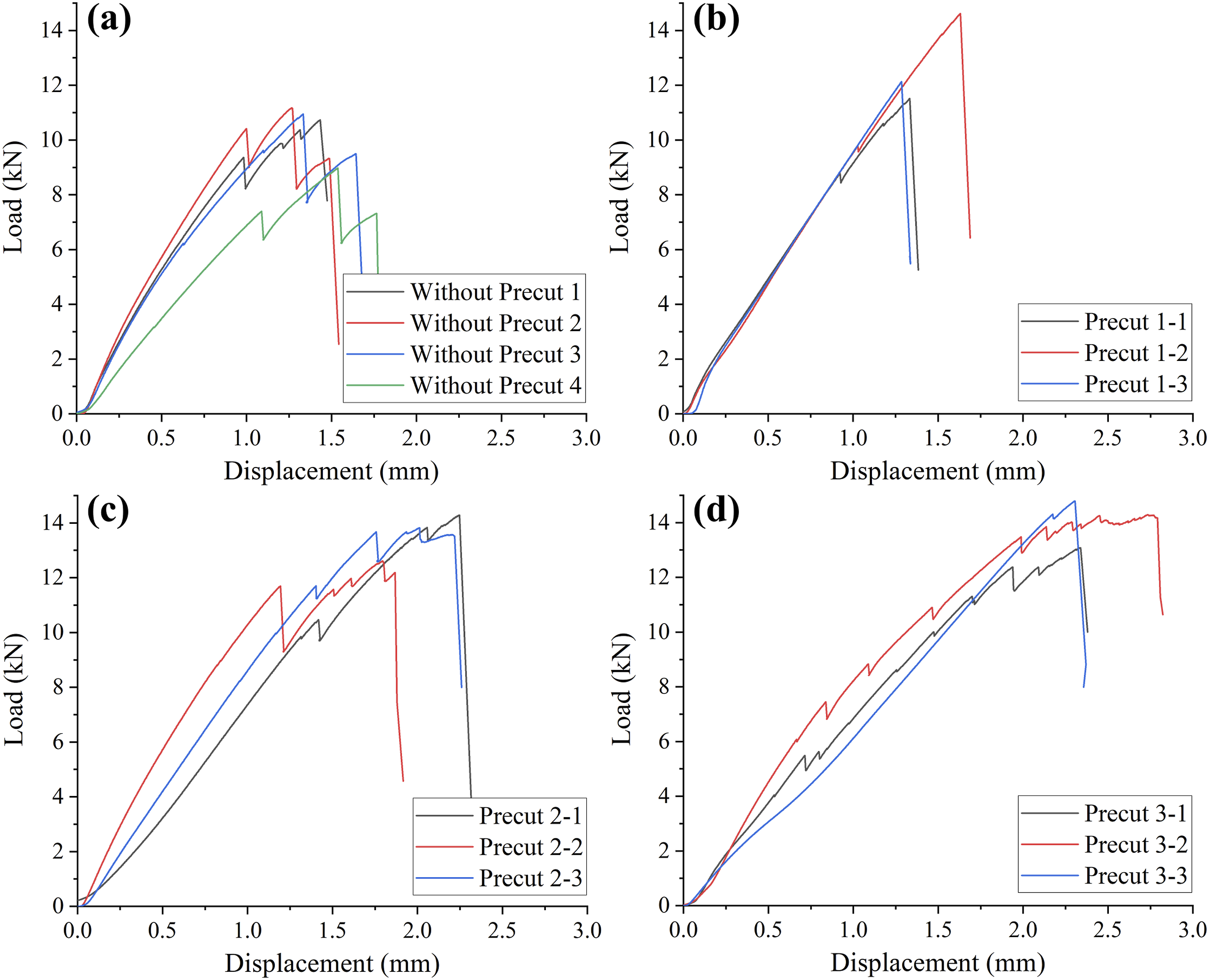
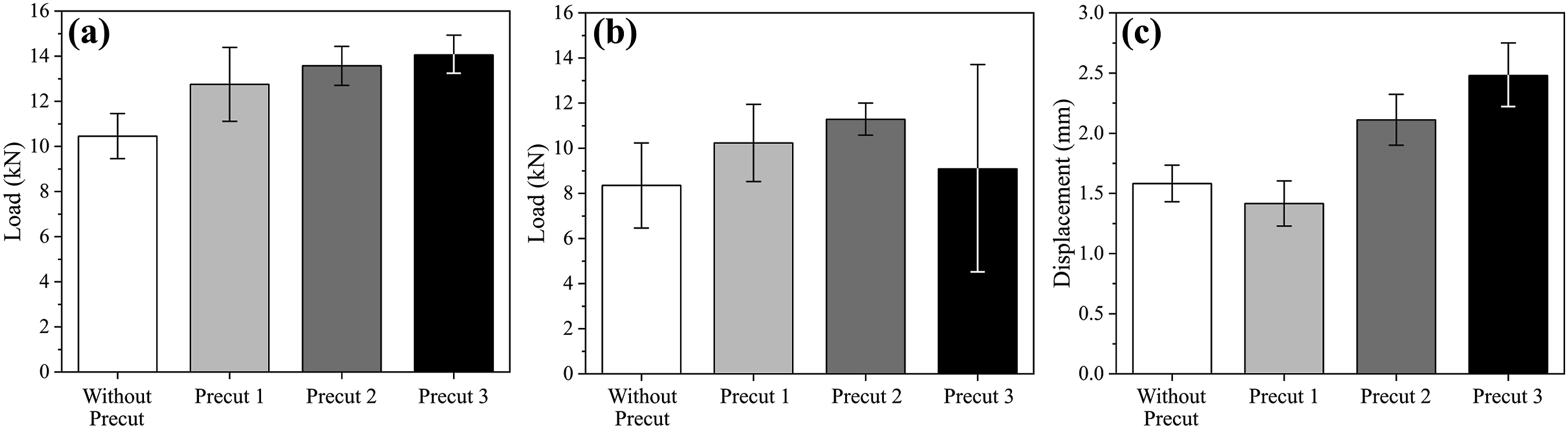
The onset failure load refers to the load at which the pin bracket begins to show signs of failure or damage. For the pin brackets made only with the recycled composite material, the onset failure load was 8.4 kN. The pin brackets made with the precut design one had the average onset failure load of 10.2 kN, indicating a 23% increase compared to the pin bracket without any precut. The pin brackets with the precut design two showed the average onset failure load of 11.3 kN, which is 35% higher than the recycled pin brackets. The pin brackets with the precut design three had the average onset failure load of 9.1 kN, which is 9% higher than the pin brackets without any precut. While the pin brackets fabricated with the precut design one and precut design two showed significant increases on onset failure load, the precut design three did not show a significant increase. The pin brackets fabricated with the precut design three showed large variation on the onset failure load. While two pin brackets out of three had an onset failure at low loads (5.5 kN and 7.5 kN), one pin bracket had highest onset failure load among all the pin brackets tested (14.3 kN).
The pin brackets fabricated with different precut designs yielded various displacement at failure values. The pin brackets without the precut had the average displacement at failure of 1.58 mm. The pin bracket made with the precut design one had the average displacement at failure of 1.42 mm, which was 10% lower than the recycled pin brackets value. The pin bracket fabricated with the precut design two and three showed higher average displacement at failure values, 2.11 mm (33.5% higher than recycled material) and 2.48 mm (56.7% higher), respectively. The load-displacement plot of the pin bracket mechanical testing showed that the pin bracket without the precuts had two or three major failures before the complete failure of the pin brackets. The pin brackets with the precut design one tended to have a single complete failure, while the pin brackets made with the precut design two and three had numerous minor load drops before the complete failure.
DIC analysis was conducted to observe local strain changes and the failure behavior of the pin brackets. The pin brackets without precuts showed significant strain changes, particularly in the upper portion of the pin hole during the test. The strain did not show a distinct pattern, but the cracks occurred in the upper region of the pin hole toward the load was applied. The failed pin bracket fabricated without precut and the DIC analysis are shown in Figure 11(a). All pin brackets made only with the recycled composite material without precuts failed in the same way. The pin brackets fabricated with the precut design one experienced a drastic strain change occurred at the middle of the ear region, where the recycled composite material was filled. The strain change in this region gradually increased and led to failure. When one side failed at the middle of the ear region, the pin tilted, and the strain on the opposite side at the middle of the ear was relieved. Eventually, the angled pin failed the ear pin hole region of the opposite side ear. The failed pin bracket fabricated with the precut design one and the DIC analysis are shown in Figure 11(b). All pin brackets fabricated with the precut design one had the same failure behavior. For the pin brackets with the precut design 2, the failure occurred at the flange where the ear and base were connected. The failure in the pin brackets with the precut design two did not happen suddenly like in the precut design 1. Instead, it occurred gradually as the ear was slowly pulled out from the base through the slots as shown in Figure 11(c). Similar to the pin brackets with the precut design 1, when one side failed at the ear-base connection region, the pin tilted, and the ear on the opposite side failed. The pin brackets with the precut design three had a similar failure behavior to those with the precut design 2. However, the strain changes in the ear region were less significant compared to the precut design two due to the greater amount of continuous fiber in the ear region. The strain changes at the flange occurred at a slower and more gradual pace compared to the precut design 2 as shown in Figure 11(d). Unlike the precut designs one and 2, the pin brackets with the precut design three experienced failures at the flange area for both ears. Images of the pin bracket after failure and local strain changes via DIC analysis for each design: (a) without precuts, (b) with the precut design 1, (c) with the precut design 2, and (d) with the precut design 3.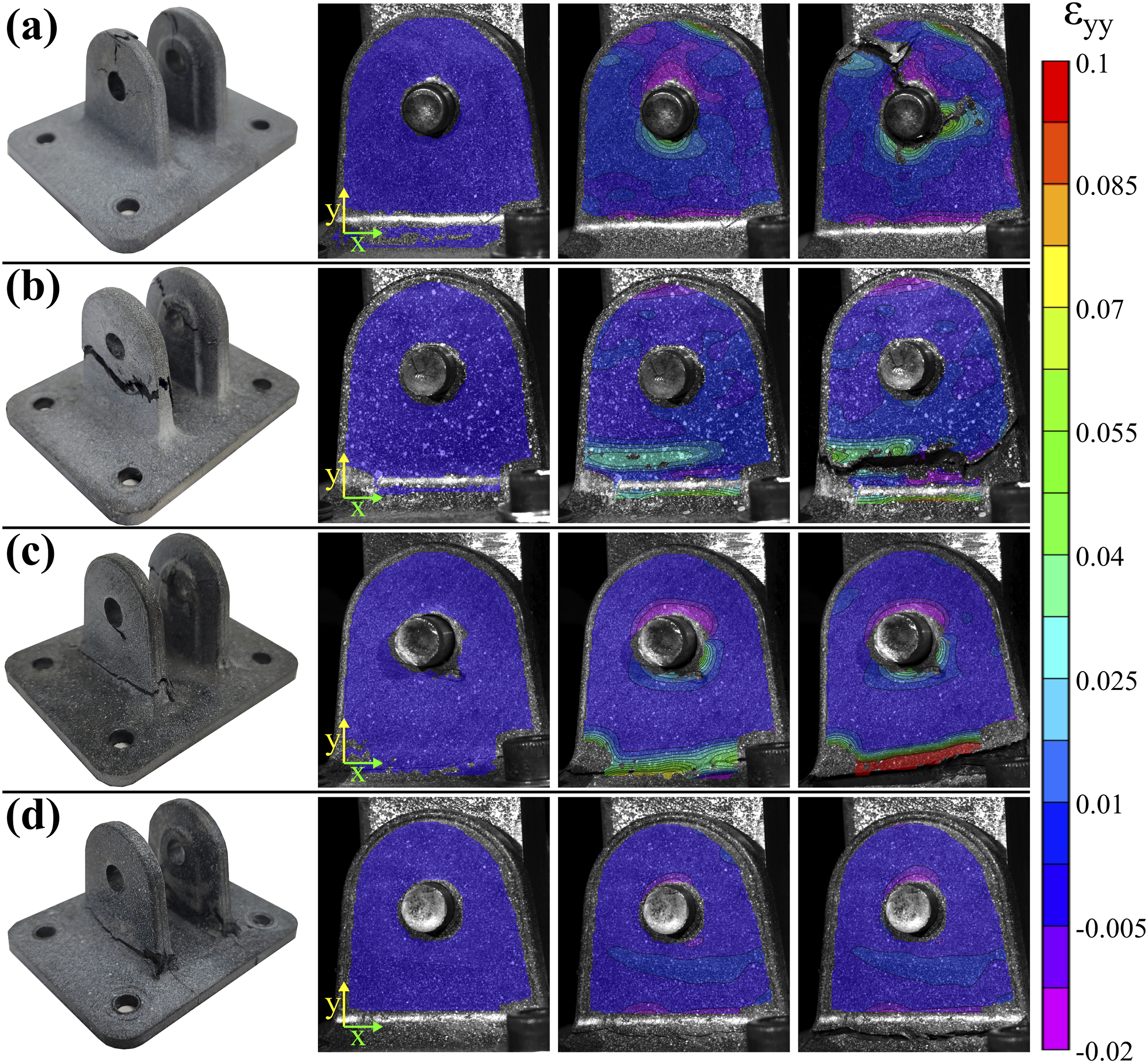
Upon examining the fractured surface of the pin brackets, as shown in Figure 12, it was observed that the fibers were not uniformly oriented in the pin brackets. During the molding process, not only did the recycled composite material flow, but the laminate also underwent deformation. This resulted in the disruption of the quasi-isotropic orientation of the original laminate precuts. The fractured surface did not show a significant number of sharp, broken fibers crossing the fracture path. Instead, the majority of fibers were oriented in the in-plane direction. As cracks formed and propagated, they tended to follow the structurally weakest path. In this case, the lack of fibers in the direction of failure resulted in lower fracture toughness, causing the crack to propagate and ultimately leading to failure along this path. The disruption of fiber orientation in the laminate precuts increases the variability in the structural performance of the pin bracket, making predictions more difficult. One of the biggest challenges in composite part recycling is variability.38,39 During the composite part mechanical recycling process. The size of the shredded composite varies, and the length of the fibers in the pellets differs. The question is whether parts made from recycled composite material can consistently and reliably perform in service, and this orientation disruption caused by precut deformation makes this even more challenging. To address this, it is necessary to develop a method that can maintain the orientation of the precuts while molding with recycled composites. Fractured surface of the failed pin bracket with the precut design 1 and 2.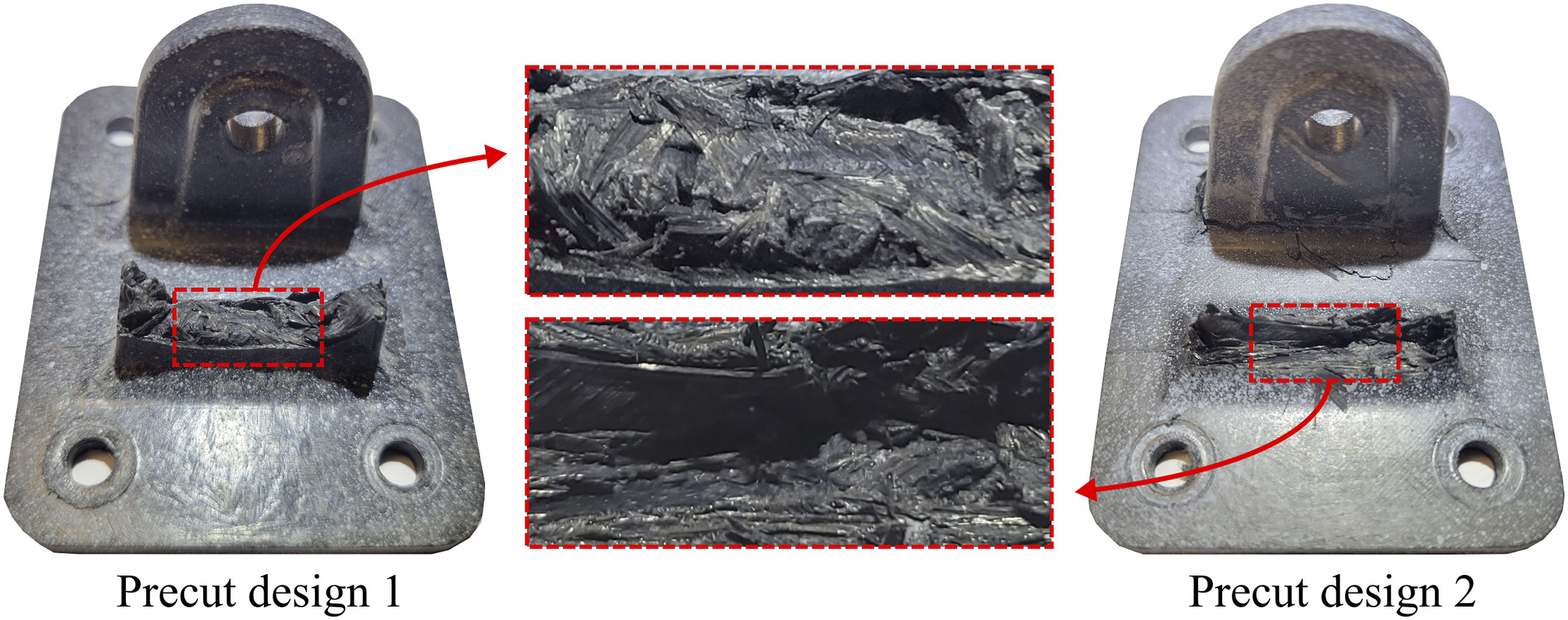
Discussion
The precut design one had a weight of 16.67 g which was approximately 53% of the total weight of the pin bracket. Integration of the precut design one resulted in an increase in the average maximum load, from 10.5 kN to 12.8 kN, increasing by 2.3 kN which is approximately 22% compared to the pin bracket without precuts. The precut design two had a weight of 19.37 g which represents that the 62% by weight of the pin bracket is continuous fiber. The average maximum load was 13.6 kN which was 3.1 kN (30%) higher than the pin bracket without precuts. The precut design three had a weight of 22.17 g which is 71% of the total weight of the pin bracket. The average maximum load increased by 3.6 kN (34%), reached to 14.1 kN, compared to the pin bracket without precuts.
The test results showed a positive relationship between the amount of continuous fiber integrated through precuts inside of the pin brackets and the corresponding increase in maximum load. Performance enhancement-to-continuous fiber content ratio also can be calculated by dividing the increased maximum load value by weight of the continuous fiber precuts for each precut design. The performance enhancement-to-continuous fiber content ratio of the precut design 1, 2, and three was 0.137 kN/g, 0.161 kN/g, and 0.162 kN/g respectively. Although the results in this study showed a positive relationship between the amount of continuous fiber and both the average maximum load and the performance enhancement-to-continuous fiber content ratio, it may vary depending on the specific precut design. Therefore, depending on the application and conditions, the prioritization can be aiming to develop the precut design that yields the highest performance enhancement-to-continuous fiber content ratio, prioritizing maximum load capacity without considering of the weight of the continuous fiber, or a combination of both factors.
Different precut designs showed different structural performance and failure mechanisms. Compared to the pin bracket without precuts, the integration of the continuous fiber precuts in the structurally critical area, where failures typically occurred at the top, prevented local failures and enhanced overall performance. The DIC results showed that the pin brackets without precuts failed at the top, while all the pin brackets with the precuts failed at the lower ear area. This indicated that the continuous fiber was effectively located in the structurally critical area, as shown in the microscopic images of the cross-sectional area of the pin brackets. In the case of precut design 1, the continuous fibers in the ear were pushed downward during molding, causing them to be tightly packed at the ear tip, resulting in a discontinuous fiber zone between the ear tip and the base. However, for precut designs two and 3, the base precut and ear precut were mechanically interlocked, preventing the ear precut from being pushed during molding. This ensured the presence of continuous fibers throughout the ear, even though the orientation changed from the original laminate during molding. Through the innovative 2D precut integration approach introduced in this paper, the integration of various continuous fiber precuts into mechanically recycled materials has demonstrated significant potential. Particularly, the use of precut mechanical interlocking technology shows not only the integration of continuous fibers but also their precise location in the final part.
This study contributes to promoting the recycling of EOL composite parts, improving the overall sustainability of composite materials, and providing valuable insights for the industry on effective ways to expand the application of recycled composite parts. However, this approach has several considerations that need to be addressed for industrial application. Firstly, not all EOL composite parts are flat. Therefore, a part flattening process may be necessary. While the flattening process may be simple for parts with simple curve shapes, there are also parts where flattening poses challenges. Therefore, careful selection of composite parts suitable for precuts is required. Also, considering the varying thicknesses of the EOL parts, a strategic planning for precut design and incorporation is required. Moreover, continuous fiber precut integration approach does not always offer the optimal utilization of continuous fibers inside of the recycled composite part. Although efforts were made to design the most suitable precuts for the part, achieving the ideal fiber orientation for the structure may not always be possible. Further research is necessary to explore more effective precut designs, strategic planning for precut processing from EOL composite part, and methods to achieve optimal fiber orientation for maximize the structural performance of the part through precuts.
Conclusion
In this study, an innovative method to enhance the structural performance of mechanically recycled composite materials by integrating continuous fiber-reinforced composite precuts was demonstrated. Through the strategic design of various precut to reinforce critical load-bearing areas of the composite parts, significant improvements on structural performance were achieved. Three different precut designs were developed and their performance were evaluated by comparing them to the pin bracket without any precut. The microscopic image of the pin brackets indicated the location and shape of the continuous fiber in the pin brackets when they were fabricated with the different precut designs.
The pin brackets featuring various precut designs showed notable structural enhancements. The precut design 1, which incorporated separate precuts for the ear and base, showed a 22% increase in maximum load compared to the pin bracket without any precuts. For the precut designs two and 3, the base precut featured slots for the insertion and interlocking of the ear precuts. In Precut Design 3, two ear precuts were used in each ear to increase the amount of continuous fiber within the pin bracket. As a result, the maximum load of the pin brackets increased by 30% and 34% with precut designs two and three respectively. Also, not only the maximum load, but the onset failure load and displacement at failure also increased. The precuts inside of the pin brackets also affected the failure behavior of the pin brackets. Without any precuts, the pin bracket failed at the top of the pin hole in the direction of the applied load due to the localized stress in that specific region. The integrated ear precuts reinforced the top of the pin hole and transferred the load to the ear and base. Overall, the precuts integrated in the pin brackets enhanced the load-bearing capacity of the pin bracket.
The integration of continuous fiber precuts to enhance the structural performance of the recycled composite part showed a promising approach to overcome the limitations associated with mechanical recycling of composite materials. By strategically designing precuts, it is possible to maximize the utilization of continuous fiber within EOL composite parts and redirect their application towards continuous fiber precuts for recycled composite part, rather than shredding them all to short fibers. This study contributes to the advancement of sustainable fiber-reinforced composite materials and introduces an innovative approach to recycling composite materials to establish an environmentally friendly and economically sustainable loop.
Footnotes
Declaration of conflicting interests
The author(s) declared no potential conflicts of interest with respect to the research, authorship, and/or publication of this article.
Funding
The author(s) received no financial support for the research, authorship, and/or publication of this article.