
Abstract
Secondary injection molding is an effective method for joining polymer parts, where the weld interface plays a critical role in the overall performance of the part. This study discusses the influence of injection molding parameters on the interface strength of polypropylene and polypropylene (PP-PP) secondary injection molding and analyzes the welding interface structure. The injection molding parameters for PP-PP were optimized using the Taguchi method and the signal-to-noise ratio (S/N). The optimal injection molding parameters were determined to be a mold temperature of 120°C, injection temperature of 350°C, and injection speed of 100 mm/s. The interface tensile strength was measured at 33.42 MPa, corresponding to 98.1% of the tensile strength of the base material. Among these parameters, mold temperature has the greatest influence on the strength of the welding interface. Secondly, polarizing microscopy, scanning electron microscopy (SEM), and Fourier transform infrared spectroscopy (FTIR) were employed to observe and analyze the crystal structure and fracture failure modes at the interface. The results indicate that elevated injection molding parameters promote the formation of crystal nuclei and spherulite growth at the secondary melt interface, with the spherulite size at the interface significantly affecting the interface strength. This study offers valuable reference for the welding of other polymers and fiber-reinforced materials.
Keywords
Introduction
With the growing demand for high-performance composite materials, material forming and processing technologies are rapidly advancing. Injection molding technology has emerged as a critical foundation for advancing composite material development due to its high production efficiency, ease of processing, and low cost. 1 For some small and simple components, the process can usually be completed in a single injection molding cycle. However, when dealing with larger or more complex components, conventional injection molding is unsuitable and requires the design of multiple parts for assembly operations.2,3 As an effective manufacturing method, secondary injection welding molding technology not only enables the design and production of complex structures but also enhances the bonding strength and durability of materials, thereby receiving widespread attention.4–6 According to statistics, within the domain of lightweight automotive manufacturing, PP and its composite materials are the most commonly used plastics, comprising approximately 60% of the non-metallic materials used in an entire vehicle. Therefore, comprehensive research on PP and its composites will significantly contribute to advancements in automotive lightweighting.7–9
During the injection molding process of composite materials, as the injection parameters are increased, the resin transitions from a viscous fluid to a highly elastic state. The mold temperature and injection temperature have a decisive impact on melt fluidity, crystallization behavior of the polymer, as well as the structure and performance of the product. Fitchmun 10 found that the crystallization of polymers is influenced by flow, shear, and temperature variations, resulting in distinct crystallization behaviors and microstructural characteristics. Particularly in the injection molding welding process, the joint is typically the weakest point of the connected components, directly impacting the integrity and reliability of the product. Butler 11 discussed the formation mechanism of polymer-polymer interface strength during the welding of thermoplastic composites. In particular, the healing and close contact of the polymer interface are key mechanisms that determine bonding strength. Specifically, for polymer injection molding of identical types, the adhesion of the joint mainly depends on the mutual diffusion between interface molecules. Under appropriate injection molding parameters, the molecules diffuse and fuse across the interface, with the final adhesion strength approaching that of the bulk material. 12 Particularly when selecting semi-crystalline polymers as welding materials, the influence of the crystal structure formed near the interface on its final strength must be considered. 13 Wu 14 used secondary injection molding to weld polyamide 6 (PA6). Differential scanning calorimetry analysis concluded that changes in interface crystallinity under different injection molding conditions significantly impact welding strength and examined the relationship between phase changes and welding strength based on this analysis. Yan 13 analyzed the interface crystal structure of overmolded polypropylene (PP) and established the relationship between the interface crystal structure and interface bonding strength. The results showed that the interface bonding strength is enhanced by strengthening the interface transcrystalline layer (TCL). Cho 15 studied the transcrystalline growth of semi-crystalline polymer interfaces and its impact on interfacial adhesion, finding that the substrate surface energy has a considerable influence on the crystallinity, core density, crystal microstructure, and thickness near the transcrystalline region. Zhong 16 conducted shear-controlled directional injection molding of isotactic polypropylene (iPP) and polyethylene terephthalate/iPP (PET/iPP) blends, discovering that the surface layer exhibited a shish-kebab crystal structure (SK), and higher crystallization temperatures were observed to inhibit secondary nucleation. Kriegl 17 studied the flow-induced nucleation process of polypropylene (PP) crystallization. The results showed that the crystallization kinetics of polypropylene (PP) changed significantly during the flow process. The chain molecules were ordered along the flow direction under the influence of flow, gradually aggregated, and grew. Yu 18 examined the flow direction, structure, and mechanical properties of polypropylene (PP) injection molding materials. Through differential scanning calorimetry (DSC) analysis, it was found that the crystallinity of the gate region and the distal part of the injection molded body was identical, which should not explain the difference in mechanical properties between the two parts. Wang 19 increased the melting point of polypropylene (PP) samples to a certain extent by modifying the injection molding pressure, which was beneficial for enhancing the crystal structure.
It is well known that during the secondary injection molding process, the polymer interface in the amorphous state facilitates mutual diffusion and fusion of molecules. However, crystallization at the polymer interface occurs, making it difficult to achieve a strong weld, often resulting in bond failure. The injection molding process parameters significantly affect the formation of the interface’s crystal structure. Optimizing parameters such as mold temperature, injection temperature, and injection speed can effectively facilitate molecular diffusion and crystallization at the interface. These parameters directly influence the melt’s fluidity, melting properties, and crystallization behavior. Öktem and Luciano20–22 used the Taguchi experimental design method to select parameters such as melt temperature, injection pressure, and cooling time for the injection molding of polymer parts. The results indicate that mechanical properties exhibit a linear relationship with the injection parameters. Arencón 23 discussed the influence of mold temperature, hold time, and mold closing time on the mechanical properties of ethylene terephthalate (PET), finding that mold temperature plays a decisive role in the development of PET matrix crystallinity, which directly affects the material’s tensile strength and elongation at break. Islam et al. 12 studied the influence of injection molding process conditions and geometric factors on the bonding strength of different two-component polymer parts, concluding that melt temperature and mold temperature have the greatest impact on bonding strength. Leong 24 used film insert technology and peeling tests to discuss the strength relationship between polypropylene (PP) films and PP substrates. The results indicated that the injection speed and barrel temperature significantly influence the bonding between the film and the substrate, with the bonding force being more strongly affected by these parameters. Aurrekoetxea et al. 25 tested the interface strength in a shear configuration and explored the influence of processing parameters on welding interface strength. Their findings showed that interface strength increases with the rise in the thermal gradient. Mosey 26 compared currently produced injection-molded components with the optimal injection molding parameters determined by research and found that welds in the injection-molded components were reduced by approximately 7.5%.
Currently, in the field of PP-PP injection molding welding, researchers primarily focus on the influence of injection molding parameters on weld strength, while relatively few studies integrate the interface crystal structure with injection molding parameters. This gap restricts a thorough comprehension of the relationship between the microstructure of the welding interface and mechanical properties, especially in interfacial studies of composite materials. Consequently, this study will investigate the combined effects of injection molding parameters and interface structure on the welding strength of PP-PP joints. Initially, injection molding parameters were optimized based on the Taguchi method, and tensile strength was used as an evaluation metric for the welding performance of the PP-PP interface to determine the optimal process parameters along with their primary influencing factors. Simultaneously, this study conducts a detailed observation and analysis of the interface crystal structure and fracture modes while employing FTIR to elucidate the influence of the interface crystal structure on welding strength, thereby enhancing our understanding of the interface bonding mechanism. Moreover, this research considers the long-term performance of the material and serves as a valuable reference for future fiber-reinforced fusion welding, thereby enhancing the overall performance of injection-molded welded components.
Materials and methods
Materials
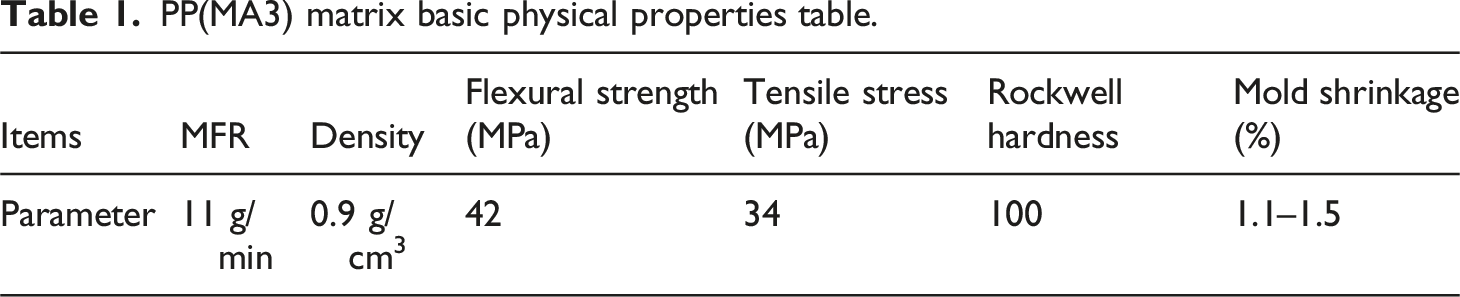
PP(MA3) matrix basic physical properties table.
Preparation of test samples
Initially, the raw PP material was dried (temperature: 80°C, time: 6 h), and then injection molded into a half-dumbbell shape using an injection molding machine (Nissei Resin Industry Co., Ltd. NP7-1 F) in accordance with JIS K 7161-2 1BA requirements. The sample is used as the first molded body. The injection molding process parameters of the first molded body are: mold temperature 40°C, injection temperature 200°C, injection speed 30 mm/s, and holding pressure 90 MPa. During the secondary injection welding process, the first molded body is manually inserted into the mold, the holding pressure remains unchanged, and the injection time is set to 10 s. After injection molding is completed, the holding time is 1 min and the cooling time is 10 min. Figure 1 presents a schematic diagram of secondary injection molding and welding. Schematic diagram of secondary injection molding fusion welding.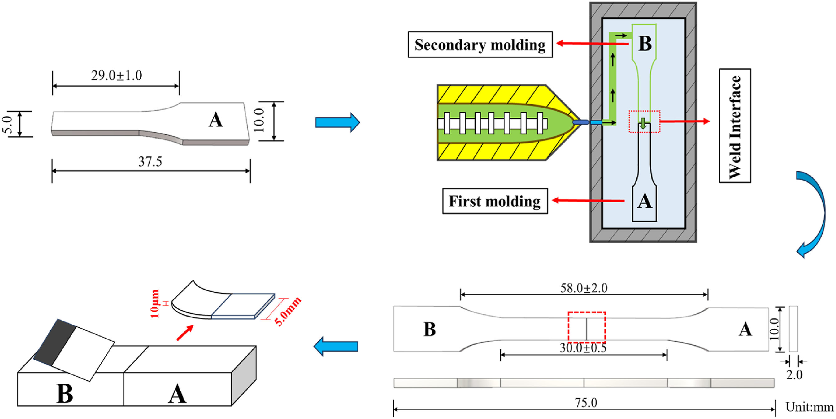
Test methods and equipment
Thermogravimetric analysis/differential thermal analysis test
To analyze the thermal properties of PP and select an appropriate injection molding temperature range, thermal gravimetric analysis (TGA) and differential thermal analysis (DTA) tests were conducted on PP using a differential thermal-thermal gravimetric analysis instrument (Shimadzu Corporation, DTG-60). PP samples, dried at 80°C for 4 h, were weighed (10 mg) and placed in aluminum pans. The temperature was then increased from room temperature to 600°C at a rate of 10°C/min under a nitrogen (N2) atmosphere.
Tensile property test
In order to assess the tensile strength of the interface after secondary injection welding, a universal material testing machine (INSTRON®, Series 3360) was used to perform a tensile test. The testing was performed at a speed of 10 mm/min and at room temperature of 23 ± 2°C. Each set of conditions was tested five times, and the results were averaged.
Observation of interface micromorphology
The connection interface and fracture morphology were observed using an optical polarizing microscope (VHX-60), and a rotary microtome (LEICA Ltd, RM2145) was used to slice the connection part with a slice thickness of 10 μm to observe and analyze the crystallization of the connection interface.
The fracture morphology of representative failed samples was observed using a scanning electron microscope (SEM, manufactured by Hitachi High-Technologies Corporation, S-4300) to analyze the morphological characteristics of PP connection interface under different injection molding conditions.
The crystalline structural changes at the welding interface were observed using Fourier transform infrared spectroscopy (Nicolet iN10MX FTIR microscope), analyzing variations at the welding interface under different injection parameters. Spectral scanning was conducted in the range of 650-4000 cm−1 with a spectral resolution of 8 cm−1.
Experimental design optimization method
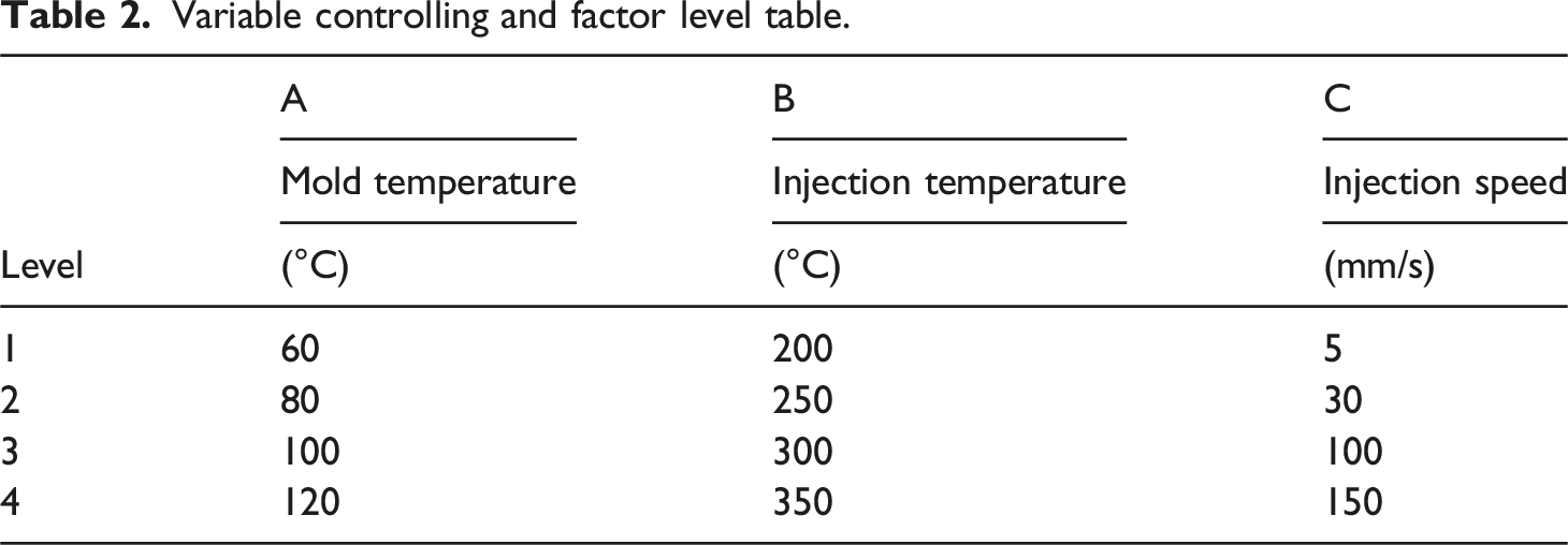
Variable controlling and factor level table.
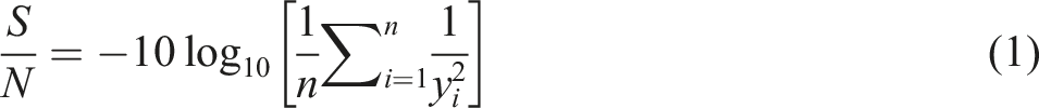
In the formula, S represents the main effect of the factor, while N represents the error effect. n denotes the number of samples in each experimental group, and
Results and discussion
PP Thermal analysis results
Figure 2 illustrates the thermal decomposition behavior of PP as measured by TG-DTA. From the TGA curve in the figure, it can be observed that the 5% thermal decomposition temperature of PP is 352°C, with complete decomposition occurring at around 450°C. The DTA curve reveals an absorption peak near 170°C, indicating the melting point. Since temperature significantly affects welding strength, this study will consider the impact of the limit values on welding strength. At the same time, the injection temperature for this study was selected based on this melting point temperature and decomposition temperature. TGA and DTA curves of PP.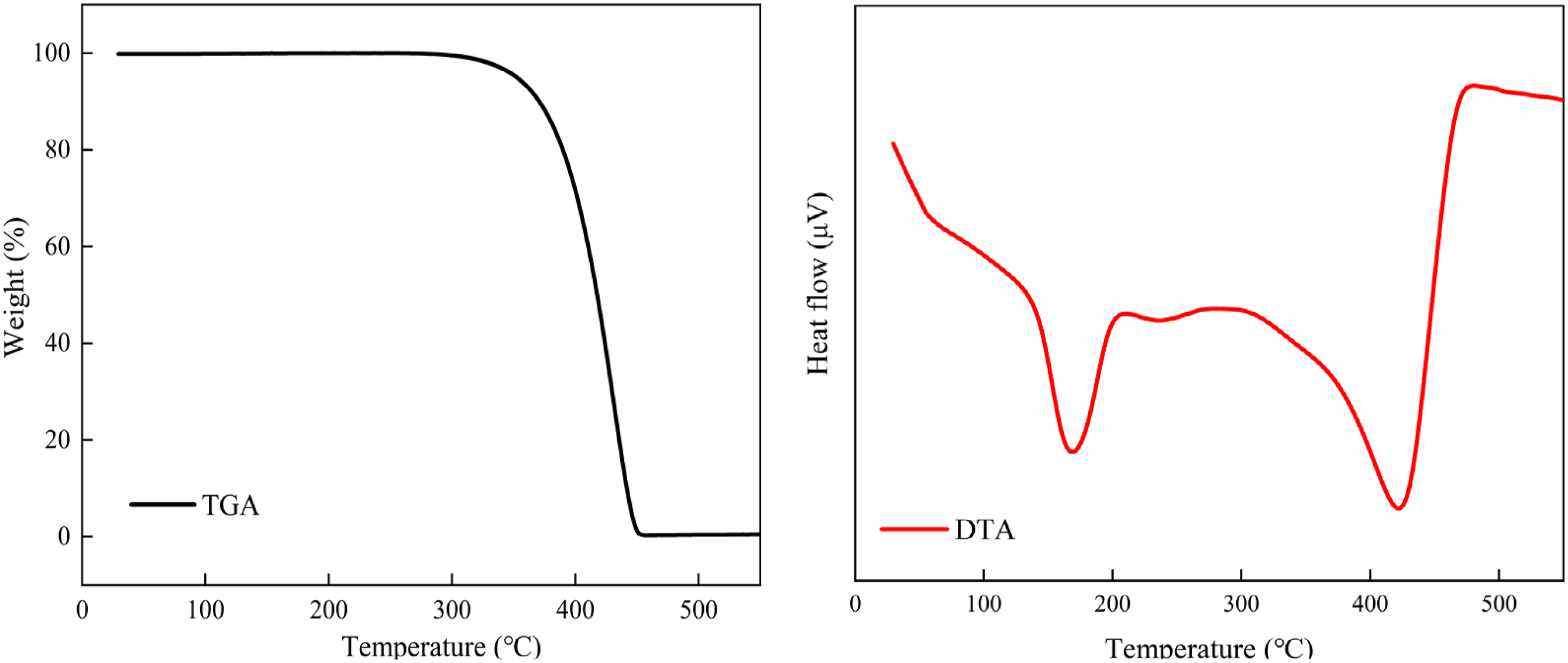
Tensile strength and S/N results
Tensile strength and S/N results.
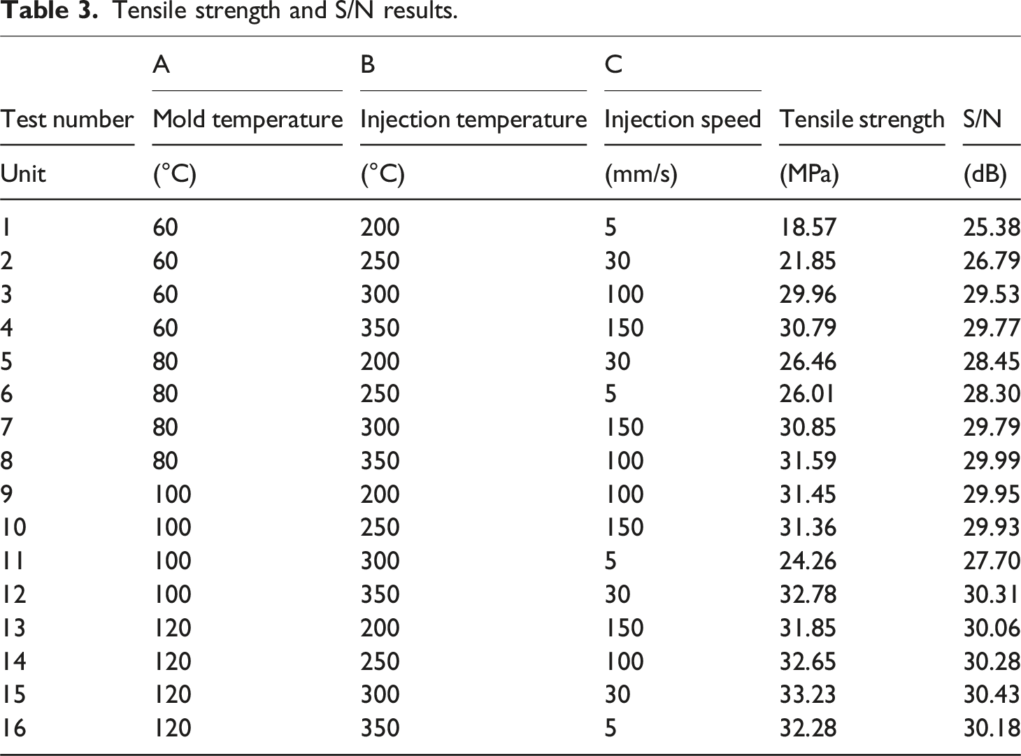
From Table 3, it is evident that under the first set of test conditions, the tensile strength was 18.57 MPa, reaching only 54.62% of the base material strength, with an S/N ratio of 25.38 dB, indicating a relatively low welding strength. In contrast, under the 15th group of test conditions, the tensile strength was 33.23 MPa, achieving 97.7% of the base material strength, with an S/N ratio of 30.43 dB, indicating the maximum welding strength. However, this is insufficient to determine which factor has the most significant impact on tensile strength. Therefore, further analysis based on the S/N ratio is required to identify the parameter that most significantly influences tensile strength.
Quantitative analysis results of tensile strength S/N range and variance values
Tensile strength S/N mean range analysis.
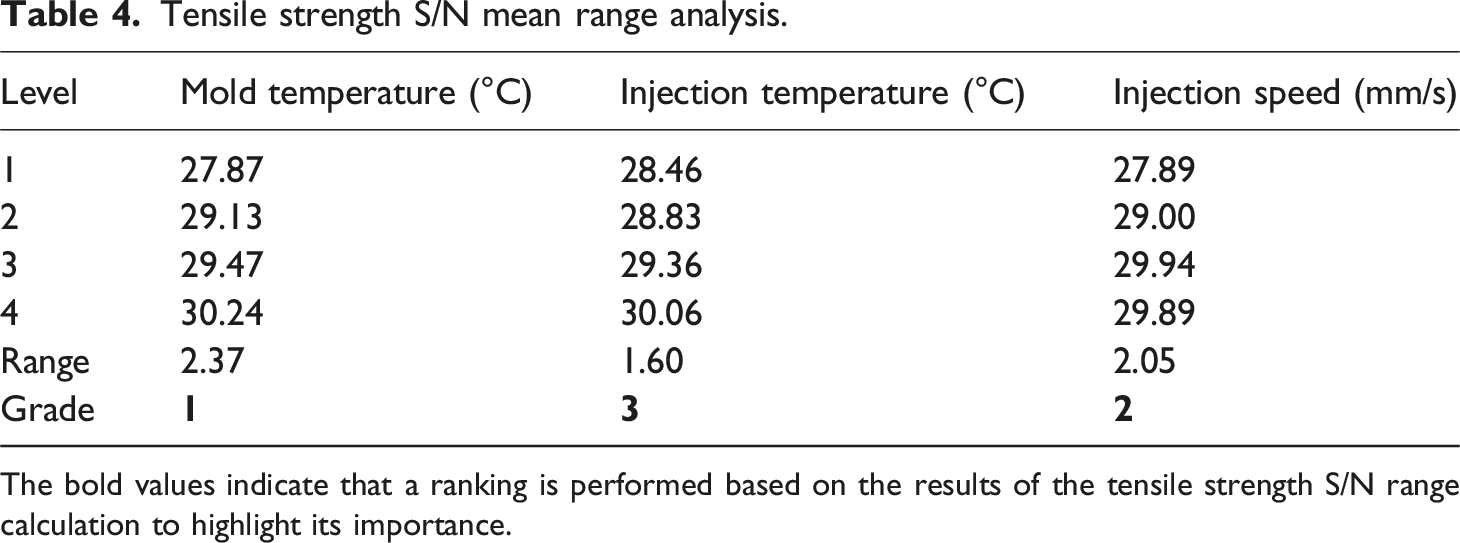
The bold values indicate that a ranking is performed based on the results of the tensile strength S/N range calculation to highlight its importance.
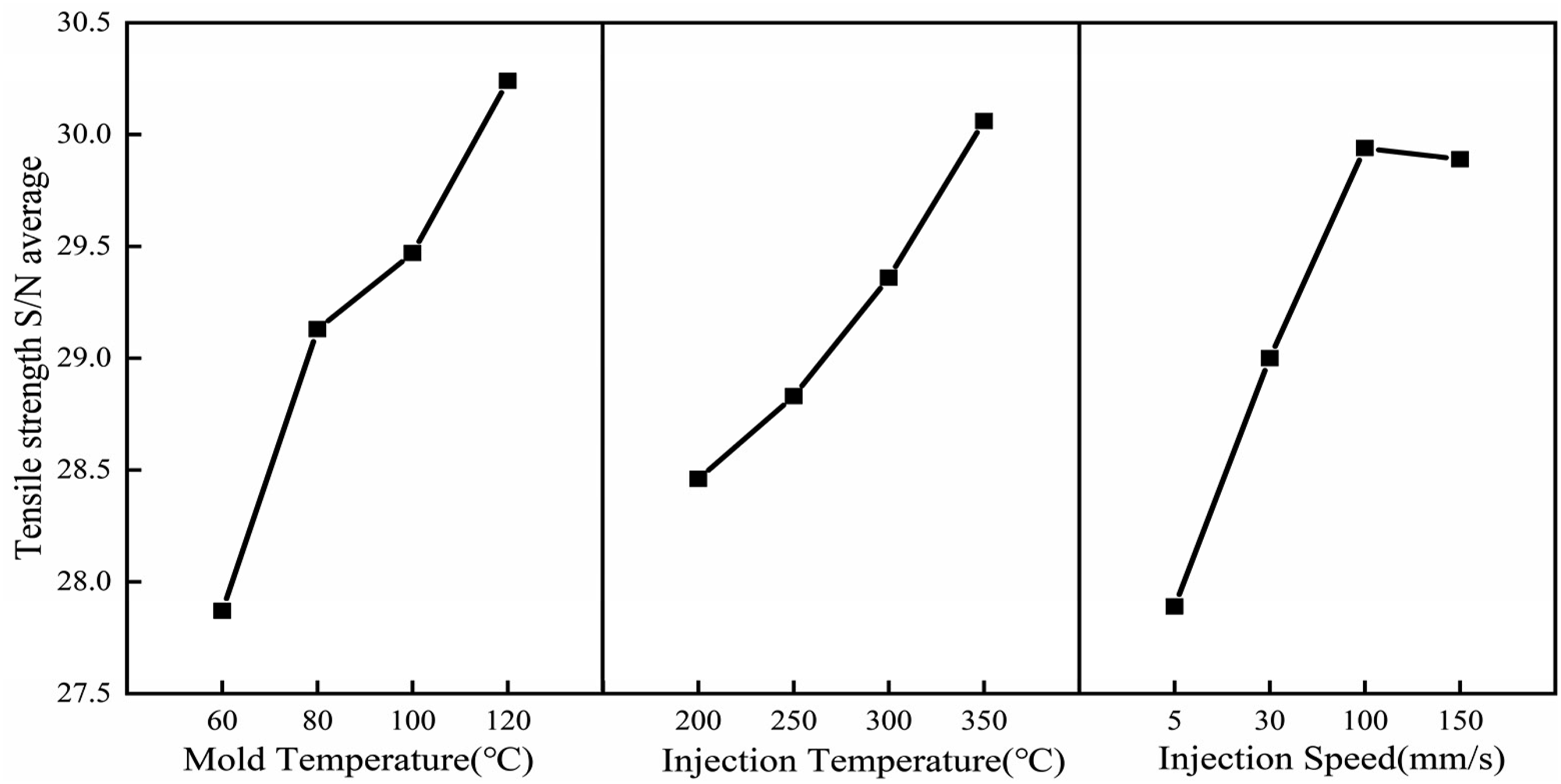
Tensile strength S/N main effect diagram.
The ranking of the range of tensile strength S/N ratios leads to the following conclusions: mold temperature (A) has the greatest significant impact on tensile strength, followed by injection speed (C), and injection temperature (B) having the least influence. These conclusions are consistent with the results of the variance analysis, as indicated by the p-value.
From the main effects diagram, it is evident that for tensile strength, the optimal injection molding parameter combination is A4B4C3, with mold temperature at 120°C, injection temperature at 350°C, and injection speed at 100 mm/s, resulting in the best performance for secondary injection welding tensile strength.
Interface crystal structure analysis results
Firstly, samples 1, 4, 8, 12, 15, and 16 were selected based on the tensile strength results for tensile performance testing, and stress-strain curves were drawn, as shown in Figure 4. Stress - Strain diagrams under different injection molding conditions.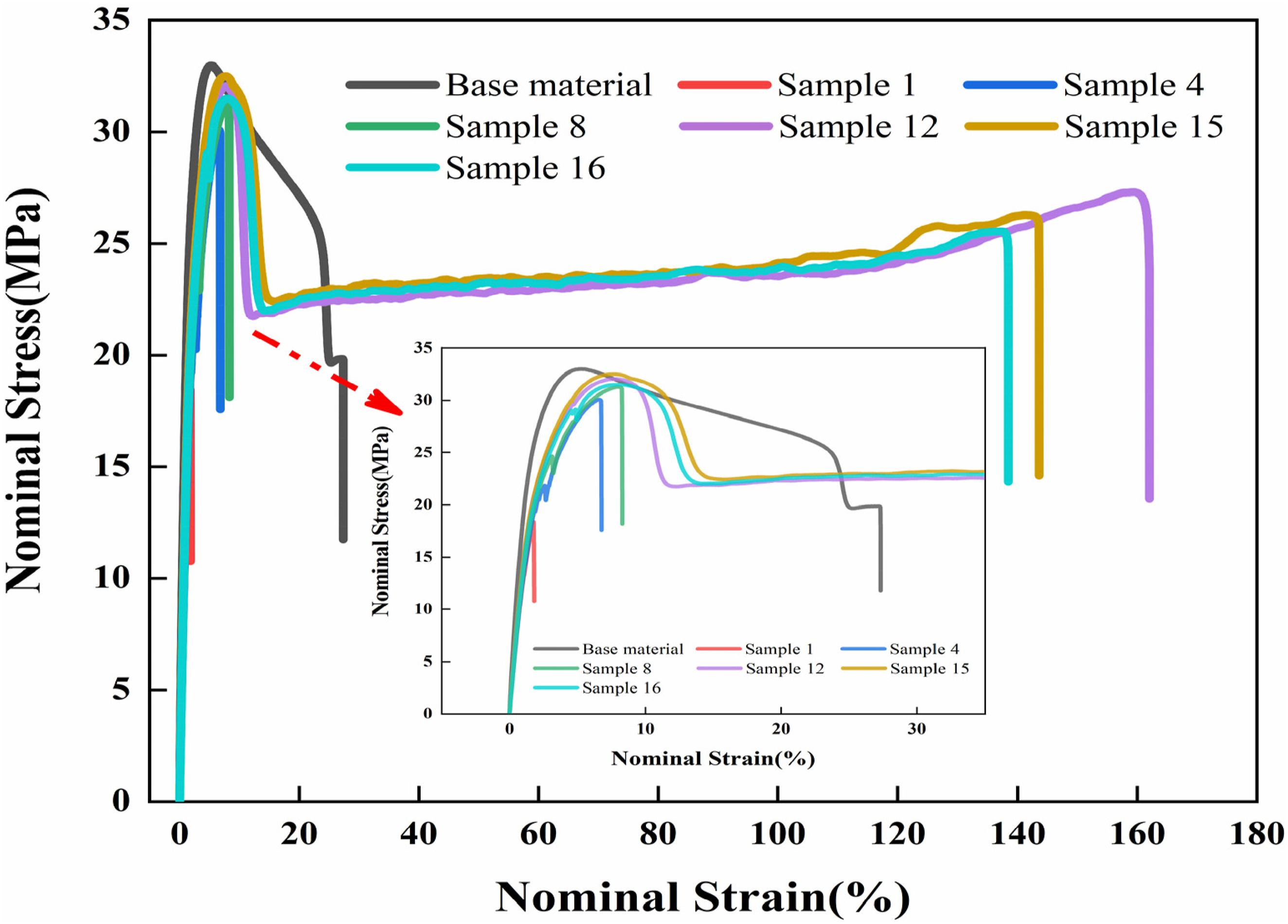
From Figure 4, it can be observed that with the increase in injection molding parameters, the tensile strength significantly increases. However, after reaching a certain strength level, the change tends to plateau, indicating that the welding effect has reached an optimal state. During the loading process, samples 1, 4, and 8 transitioned from the elastic stage to the yield stage, then enter the strengthening stage. Upon reaching the maximum tensile strength, the load suddenly decreases due to material reaching its limit, leading to complete specimen failure with brittle fracture characteristics and fracture elongation significantly lower than that of the base material. Conversely, the failure strains of certain welded samples (such as samples 12, 15, and 16) are significantly higher than those of the PP base material. This is due to the fact that compared with the lower molding parameters of the base material (mold temperature: 40°C, mold temperature: 200°C and injection speed: 30 mm/s), during the secondary injection molding welding process, the increase in mold and injection temperatures facilitates effective molecular diffusion and fusion at the PP-PP interface. Furthermore, the welding strength of the samples surpasses the yield strength, indicating enhanced ductility; they first undergo plastic deformation before experiencing fracture failure. Consequently, this results in higher failure strains compared to the base material.
Next, to observe the influence of crystalline structure at the interface under different injection conditions on welding strength, the selected specimens’ welding interfaces were sliced(10 μm), and the crystallinity at the welding interface was observed using a polarizing microscope, as shown in Figure 5. Interface crystallization structure diagram under different injection molding conditions. (a) Interface Crystal Structure of Sample 1 (Mold temperature: 60°C, Injection temperature: 200°C, Injection speed: 5 mm/s) (b) Interface Crystal Structure of Sample 4 (Mold temperature: 60°C, Injection temperature: 350°C, Injection speed: 30 mm/s) (c) Interface Crystal Structure of Sample 8 (Mold temperature: 80°C, Injection temperature: 350°C, Injection speed: 30 mm/s) (d) Interface Crystal Structure of Sample 12 (Mold temperature: 100°C, Injection temperature: 350°C, Injection speed: 30 mm/s) (e) Interface Crystal Structure of Sample 15 (Mold temperature:120°C, Injection temperature:300°C, Injection speed:30 mm/s) (f) Interface Crystal Structure of Sample 16 (Mold temperature: 120°C, Injection temperature: 350°C, Injection speed: 5 mm/s).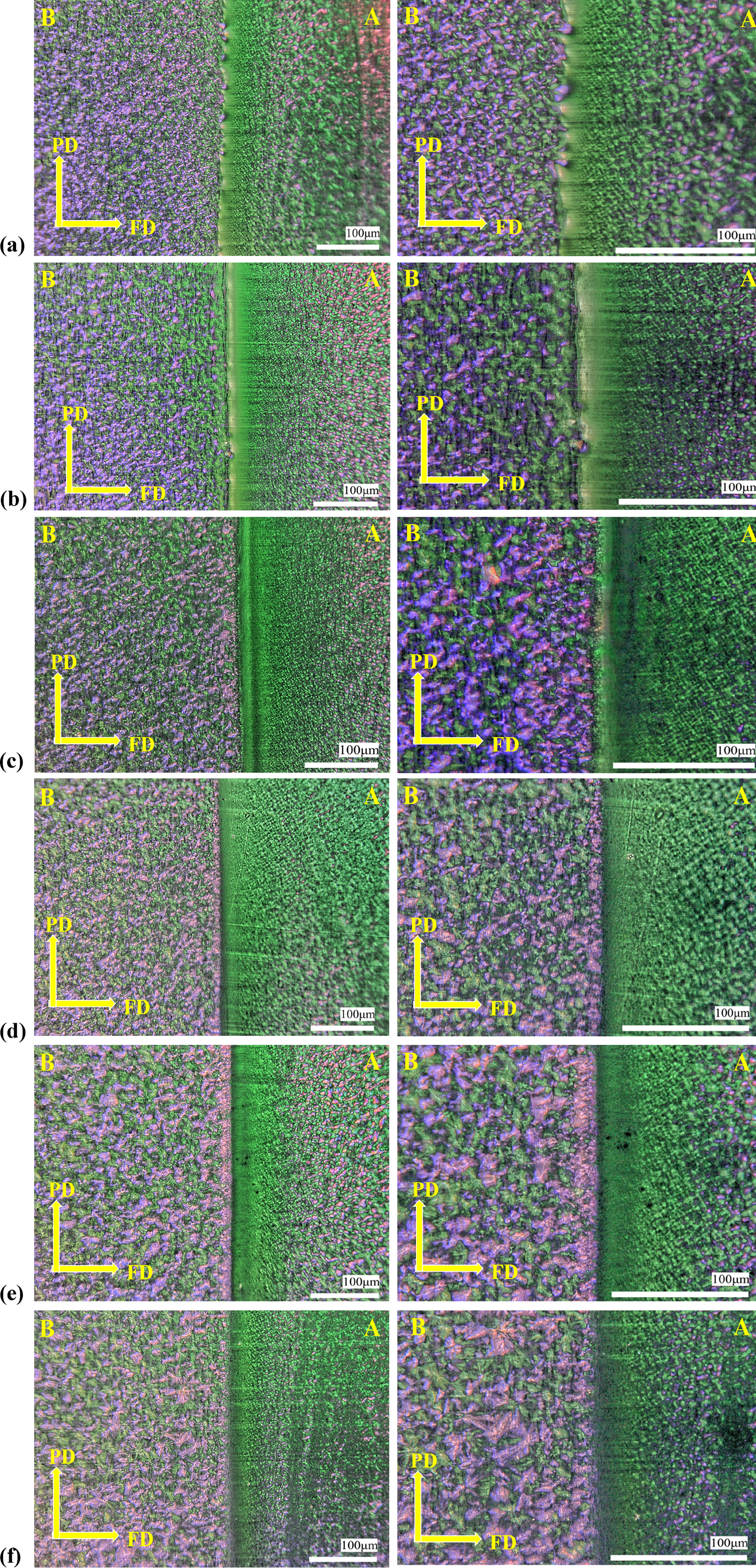
From Figure 5(a)–(f), it is evident that with the increase in injection molding parameters, the welding interface transitions from having obvious weld line to a more continuous and uniform structure. And the width of the weld seam also increases, enhancing the strength and stability of the interface further. It can be seen from the interface crystalline structure at the interface indicates that the size of interface spherulites significantly impacts welding performance. 30
From sample 1, a distinct boundary line can be observed at the interface. In the secondary molding body (B), the spherulite size is generally smaller, and along the FD direction, the crystalline density of α-PP decreases with no significant change in spherulite size. This is attributed to the mild injection molding conditions, resulting in the failure to form an obvious spherulite structure at the interface.
As temperature and injection speed increase, the fusion lines at the interface of sample 8 appears smoother and clearer. Along the FD direction, the crystalline density and spherulite size of α-PP gradually increase. Simultaneously, along the PD direction, a dense and continuous microcrystalline structure can be clearly observed at the junction with the first molding body (A). This is because as the temperature and injection speed of the secondary melt increase, the secondary melt exhibits greater molecular activity and diffusion capacity when it contacts the first molded body. The molecules rapidly diffuse at the interface and cross the grain boundaries. However, the high nucleation density of the crystalline structure on the surface of the first molded body restricts the lateral extension of the secondary melt, and as the temperature quickly cools and solidifies, a crystalline layer forms perpendicular to the interface, this structure is called an interface Transcrystalline Layer (TCL).31–33 The formation of TCL is one of the necessary conditions for promoting enhanced crystallization at the interface in injection welding. Not only does it help to enhance the adhesive strength of the welding interface, but it also improves the stability and durability of the interface.
Compared with sample 8, the spherulite structure of α-PP at the interface of sample 15 appears larger and more continuous. This is due to the further increase in mold temperature, which allow PP molecules to sufficiently align and diffuse at the interface. On the other hand, the high temperature and high speed promotes the formation and growth of nuclei. The formation of this structure helps to enhance the bonding performance of the welding interface, and its toughness is also strengthened. It is important to note that the crystallinity in the welding area is not consistent with that in the regions away from the weld. This discrepancy arises because crystallinity is influenced by molding conditions; when the molding conditions differ, the crystallinity will also change.
Surface roughness and cross-section damage analysis results
The welding interfaces of samples 1, 8, and 15 were selected respectively, and the roughness of their surface fusion lines and weld seams was observed and analyzed using a polarizing microscope, as shown in Figure 6. Surface roughness under different injection molding conditions. (a) Sample 1 (b) Sample 8 (c) Sample 15.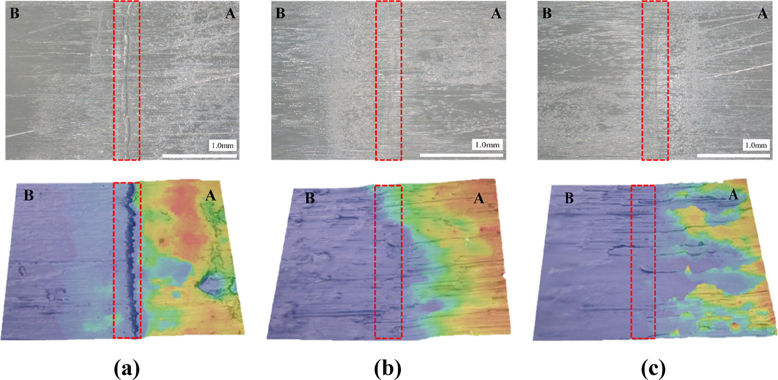
From the Figure 6, it can be clearly observed that as temperature and injection speed increase, the surface weld seam at the interface of the secondary injection molded body gradually becomes smoother. This phenomenon may originate from the injection molding process where, as temperature and injection speed increase, the front end of the secondary melt appears liquid, upon contacting the first molded body, it exhibits good viscoelastic properties. Simultaneously, the flow friction between the secondary melt and the mold walls decreases, allowing the surface molecular chains to diffuse more easily. Also, the interface of the first molded body melts as the temperature rises, leading to the development of a more homogeneous polymer interface. As a result, this manifests as a decrease in seam roughness and an increase in bonding strength, further highlighting the significant impact of temperature and speed on welding strength.
Next, the interface failure modes and cross-sectional morphologies of the three samples were observed and analyzed, as shown in Figures 7–10. Tensile failure modes under different injection molding conditions. Cross-sectional morphology of interface separation type failure. Cross-sectional morphology of mixed interface failure. Cross-sectional morphology of matrix material failure.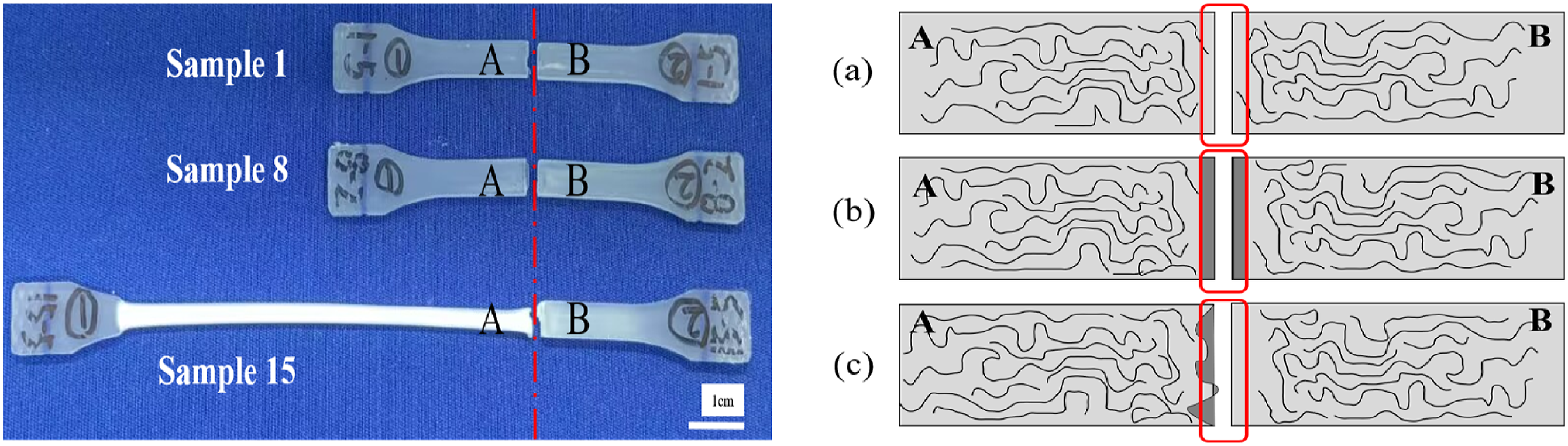
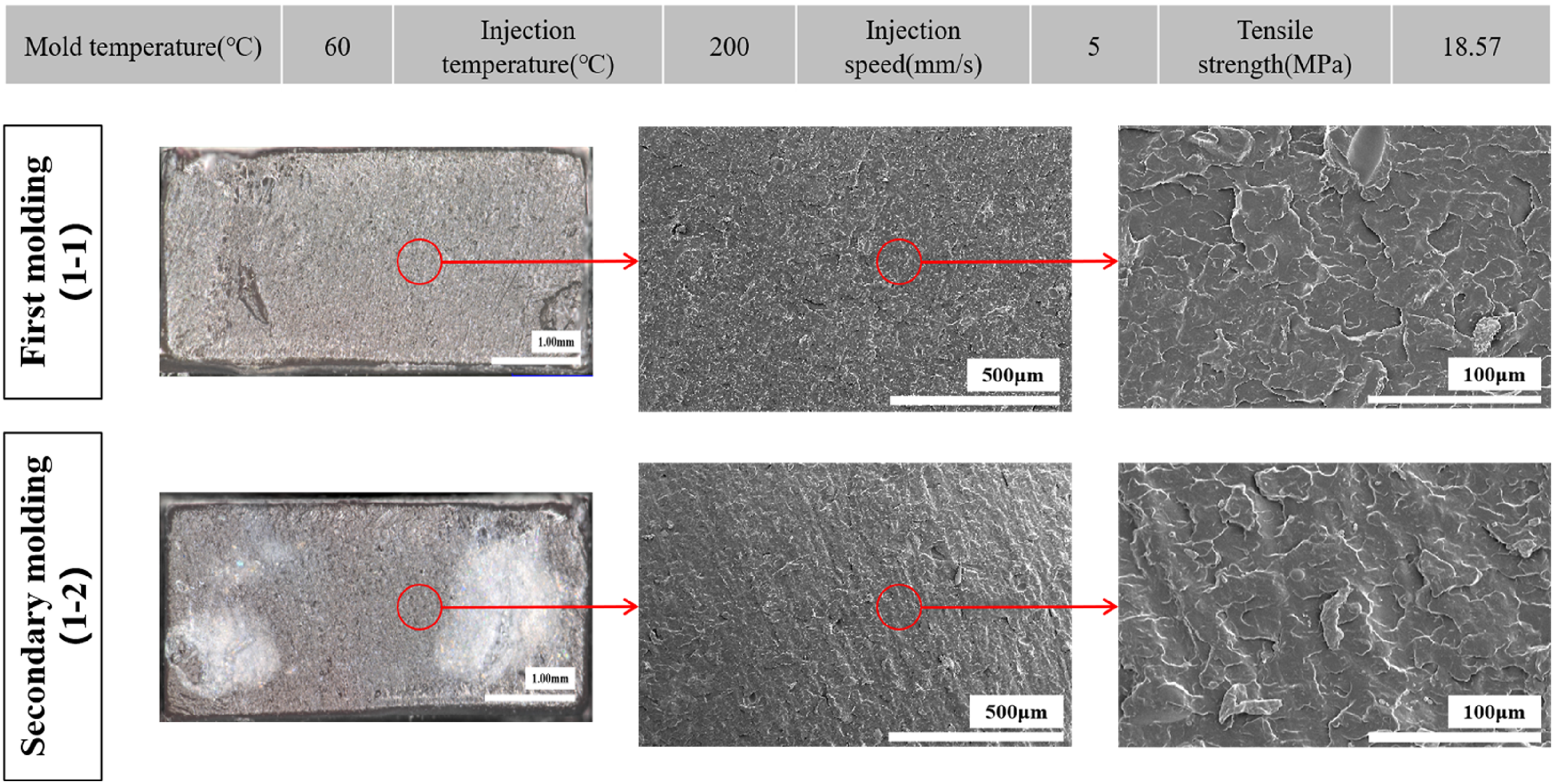
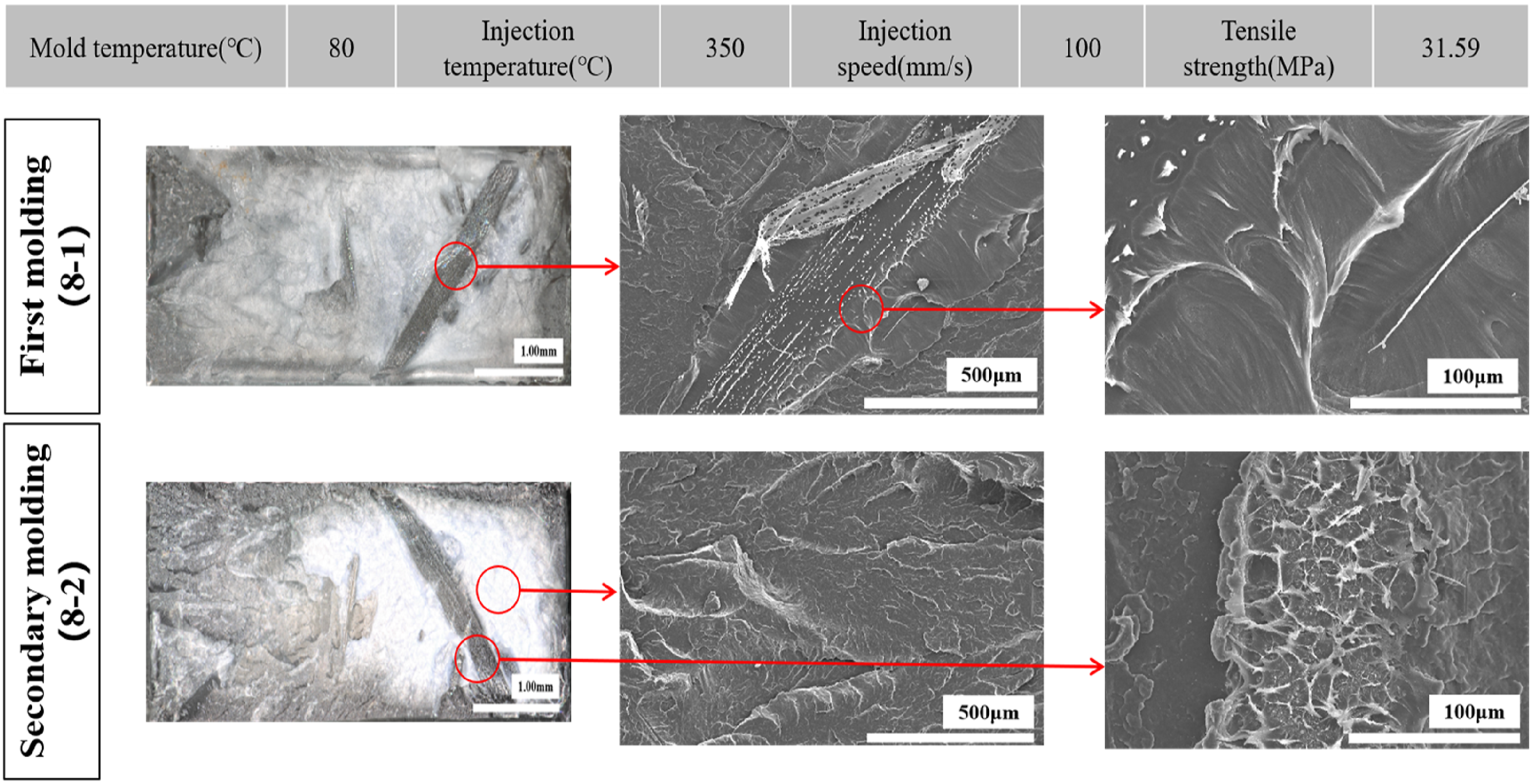
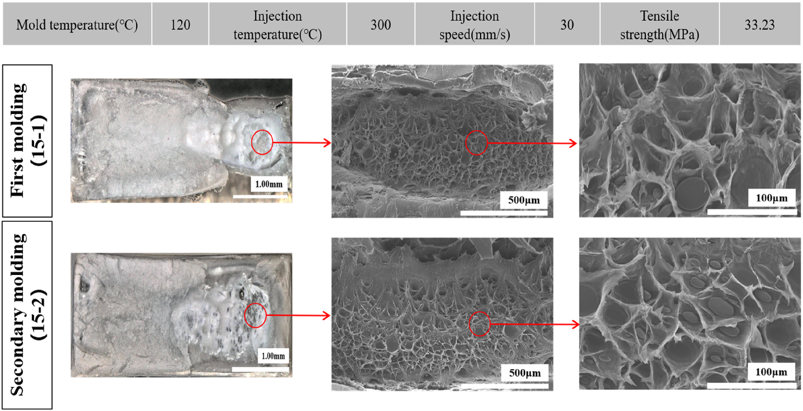
As illustrated in Figure 7, Sample 1 represents (a) interface adhesion failure, Sample 8 represents (b) interface mixed failure, and Sample 15 corresponds to (c) substrate failure. 34 With increased temperature and injection speed, the material failure mode progresses from the interface to the substrate, and the extent of failure deformation gradually approximates that of the base material. Under conditions of high temperature and rapid injection, the secondary melt of PP more readily achieves effective fusion between the welding interface and the base material, thereby enhancing the overall strength and durability of the welded joint.
It can be clearly shown in Figure 8, the cross-sections of both the first and second molding bodies of Sample 1 are relatively smooth. This is due to the relatively low injection parameters during the secondary injection welding process, which led to a reduced diffusion rate of the molecules at the interface of the secondary melt interface. This means that the molecular chains between the resins fail to form an effective cross-boundary bond. Consequently, this resulted in lower welding strength, manifesting as characteristics of interface separation type failure.
As clearly depicted in Figure 9, the cross-sections of the first and second molding bodies of Sample 8 exhibit a resin bonding morphology. This occurs because, during the secondary injection welding process, the temperature, and injection speed are increased, with the injection temperature significantly exceeding the melting temperature of the resin. This condition enhances the diffusion rate of the molecules at the interface of the secondary melt interface, allowing it to thoroughly encapsulate the interface of the first molding body. Furthermore, as the temperature decreases, the interface resins of both bodies intertwine, resulting in tighter adhesion and thereby increasing the welding strength, which is characterized by mixed failure at the interface.
It can be clearly seen from Figure 10 that the failure mode at the welding interface is matrix material failure, with the cross-sections of both the first and second molded bodies displaying a distinct honeycomb-like morphology. The location of the failure has shifted from the interface to the substrate of the first molded body, where significant necking of the first molded body is also observed, indicating optimal welding conditions. This is due to the increase in mold temperature during the secondary injection welding, which enhances the mobility of the molecules at the interface of the first molded body, initiating melting. Under the impact of high injection temperature, the secondary melt quickly intertwines with the molecules at the interface of the first molded body, forming a well-fiberized columnar structure. At this time, the interface welding strength is considered to have reached the strength of the substrate material.
Interface infrared analysis results
According to the literature,35–38 PP has three strong groups of infrared characteristic absorption bands within the frequency range of 400–3500 cm−1. The absorption bands within the 2800–3000 cm−1 range are attributed to the C-H stretching vibration modes of PP; those within the 1300–1500 cm−1 range correspond to the C-H bending vibration modes; and those within the 800–1000 cm−1 range pertain to the crystalline vibration modes of PP. Specifically, the absorption peaks at 1166 cm−1, 997 cm−1, 972 cm−1, and 840 cm−1 are related to the crystallinity of PP and are identified as the crystalline absorption peaks of PP. The intensity of these crystalline absorption peaks can be used to determine the degree of crystallinity at the welding interface.
To further investigate the impact of crystalline structure at the welding interface on welding strength under different injection molding conditions, FTIR scans were performed on the welding interfaces of samples 1, 8, and 15 using a surface scanning approach. For example, the absorption peak at 972 cm−1 is illustrated in Figure 11. Interface infrared analysis results under different injection molding conditions ((a) Scanning area of the welding interface (b) 2D spectral image of the welding interface (c) 3D spectral image of the welding interface).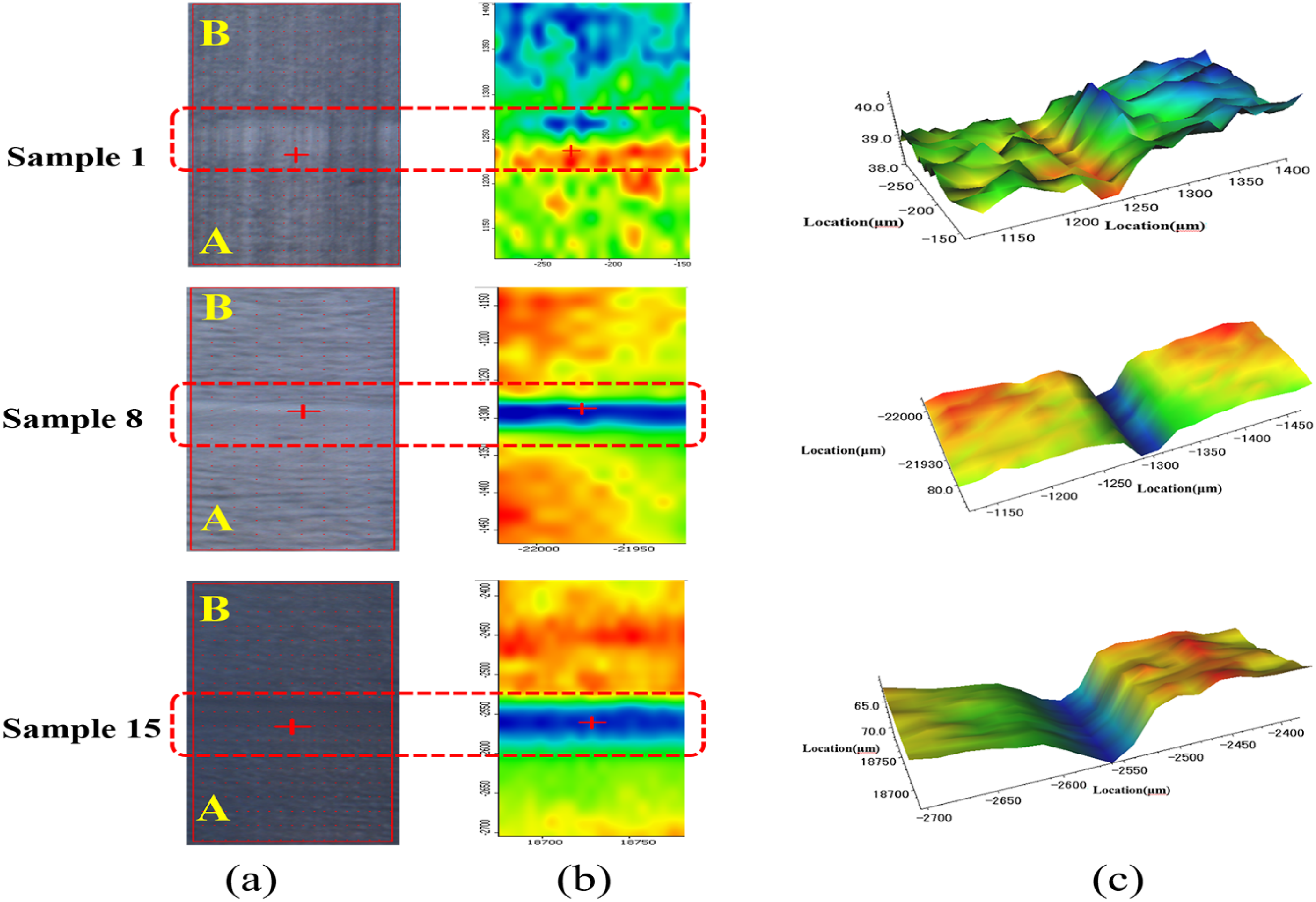
Within the red dashed-line area of the welding interface, the corresponding 2D spectral image reveals spectral bands in different colors, indicating crystalline structures. The blue striped bands represent the crystalline structure of the welding interface, and the green striped bands indicate the crystalline structure of the transition zone between the molded body and the welding interface. As the temperature and injection speed increase, the width of the interface crystalline structure noticeably widens, consistent with the trend of interface crystallinity changes observed in Figure 5. This occurs because the increase in temperature and speed during the injection molding process enhances the diffusion rate of the secondary melt molecules, allowing the PP molecules at the interface to more easily realign and reorganize. This leads to the formation of larger and more continuous α-PP crystalline structures, which exhibit stronger absorption peaks in the same regions of the infrared spectrum due to their highly ordered crystalline structure.
For Sample 1, due to lower injection molding conditions, when the secondary melt contacts the first molded body, its molecular arrangement is looser and the vibrations between molecules is freer. Consequently, this is manifested as weaker absorption peaks in the infrared spectrum. Correspondingly, the blue striped bands are not distinct, while the stronger red striped bands represent boundary crystallization after the secondary melt cools, indicating a poorer connection effect and lower welding strength. Similarly, from the corresponding 3D spectral image, it is clearly visible that as the temperature and injection speed increase, the spectral width and depth at the welding interface also increase.
Conclusions
This study is based on Taguchi analysis method and improves the interface strength of polypropylene butt welding by optimizing the injection molding process parameters. According to the main effect diagram of S/N, it was determined from the main effects diagram of the S/N ratio to be a mold temperature 120°C, injection temperature 350°C, and injection speed 100 mm/s, achieving a welding tensile strength of 33.42 MPa, which is 98.1% of the base material strength. Analysis of the crystalline structure at the welding interface revealed that the size of the spherulites significantly influences welding performance. The formation of the Transcrystalline Layer (TCL) at the interface plays a crucial role in enhancing the adhesive strength, as well as improving the stability and durability of the interface. Under low injection conditions (Sample 1), tensile failures predominantly exhibit brittle fracture, whereas under high injection conditions, failures occur mainly through plastic deformation. Additionally, under high temperature and high-speed injection conditions (Sample 15), the diffusion rate of the secondary melt’s interface molecules is enhanced, allowing for more effective bonding with the interface of the first molded body. This results in a tighter adhesion at the interface, thereby strengthening the welding strength. Lastly, the influence of the interface crystalline structure on welding strength was further verified by scanning the welding interface crystalline structure using FTIR.
Footnotes
Acknowledgements
Dr Tang wishes to acknowledge the financial support from the program of China Scholarship Council (202308050017). The authors would like to express their sincere thanks to Jianhui Qiu, Eiichi Sakai, Guohong Zhang and others for the assistance of project.
Declaration of conflicting interests
The author(s) declared no potential conflicts of interest with respect to the research, authorship, and/or publication of this article.
Funding
The author(s) disclosed receipt of the following financial support for the research, authorship, and/or publication of this article: This work was supported by China Scholarship Council (202308050017).