
Abstract
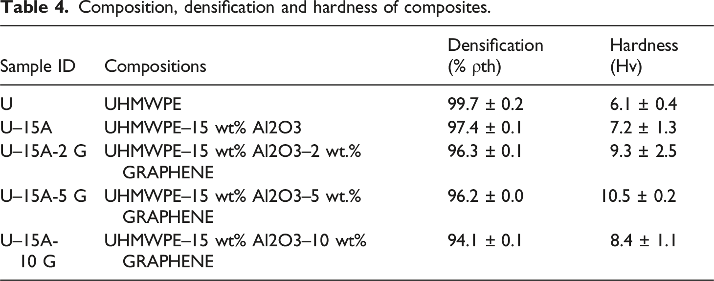
Aluminium oxide and graphene reinforced with ultrahigh molecular weight polyethylene (UHMWPE) composites offer significant potential for prosthetic and implant applications due to their unique combination of properties. In this article, a series of aluminium oxide and graphene reinforced with ultrahigh molecular weight polyethylene (UHMWPE) composites were successfully fabricated through compression moulding. The average hardness of all the composites was observed to be higher than the UHMWPE (6.1 Hv). Composite U-15A-5 G was found to be the hardest with hardness of 10.5 Hv owing to strong bond between Al2O3 and UHMWPE. The compression strength of the U-15A-5 G material was about 81.936 MPa, which is 40.9% better than the pure UHMWPE. The compression modulus was about 330 MPa which is 22.2% higher than neat UHMWPE. Composite samples were tribo tested under simulated body fluid (SBF) lubricating environment. Using combined entropy-COCOSO method it was found that 50 mm/s speed, 200N load and 5% graphene are the optimum tribological parameters. with Cof of 0.04 and wear rate of 4.8745*10−4 mm3/Nm. Microstructure analysis indicated that long-range structured lamellar structures and microfibers were created between the crystals with the assistance of graphene layers. Apatite layer was also found on the sample. The apatite layer included phosphate and carbonate ions, which is good for in vitro bioactivity on polymeric films. This composite is a good candidate for prosthetics and implant components.
Introduction
Biomaterials are materials that are designed and engineered for use in medical and biological applications, particularly in the field of healthcare. They can be natural or synthetic substances that interact with biological systems, ranging from cells and tissues to organs and organisms. Biomaterials play a crucial role in various medical applications, such as drug delivery, tissue engineering, regenerative medicine, medical implants, and diagnostic tools.1,2 Versatile materials such as metals, polymers, ceramics are used as biomaterials. Material combinations like polymer-ceramic composites or polymer-metal composites offer enhanced properties and functionality. 3
Inappropriate material selection, including issues such as wear resistance, corrosion, or biocompatibility, can lead to premature implant failure. Failures in orthopedic implants can occur due to various factors, leading to complications and the need for revision surgeries. Implants may fail if they are subjected to excessive mechanical stress or loading beyond their intended capacity. Over time, repetitive loading and motion can cause wear and fatigue in implant materials, leading to component failure or generation of wear debris. However, one of the most important aspects that must be taken into account for an implant to be effective is its biocompatibility and cytotoxicity, which are brought on by the implants and might result in unfavorable biological reactions and implant failure. 4
Some non-destructive alternatives were also devised to enhance the wear performance of the composites while preserving the original qualities of the materials. When fabricating prostheses with superior performance over fresh polyethylene components for complete joint replacement, the optimum approach is to strengthen a polymer matrix with both organic (carbon fibers, graphene, and zirconia) and inorganic (Al2O3) fillers. 5 Ultrahigh molecular weight polyethylene (UHMWPE) has been utilized in hip and knee total joint replacement as a bearing material for an acetabular prosthesis component because of its special qualities, which include low friction coefficient, excellent biocompatibility, and high impact strength. 6 However, because of its low Young’s modulus, poor load bearing, and inadequate anti-fatigue ability, the usage of UHMWPE has been restricted.7–9 Alumina is a ceramic material known for its excellent mechanical properties, including high hardness, stiffness, and wear resistance. It’s also biocompatible, meaning it’s generally well-tolerated by the body. 10 A single sheet of carbon atoms organized in a hexagonal lattice is called graphene. It is well known for having remarkable electrical conductivity, strength, and flexibility. Incorporating graphene into composites can enhance their mechanical properties and potentially provide other benefits, such as improved biocompatibility and conductivity. 11
Researchers have tried a number of approaches to improve UHMWPE’s mechanical and wear resistance. While pure UHMWPE showed Cof of 0.40 and wear rate of 4.7*108, UHMWPE reinforced with 0.1%, 0.5%, and 1% graphene resulted in Cof of 0.35, 0.28, and 0.24 and wear rate of 3.7*108, 3*108, and 1*108 mm3/m. Graphene can reduce wear and offer continuous lubrication while sliding when added to UHMWPE.
12
Another researcher reinforced UHMWPE with 0.1% ,0.3%,0.7% and 1% Graphene
Reinforcing UHMWPE using 1 wt% multiwalled carbon nanotubes (MWCNTs) increased ductility by approximately 140% and modulus by around 25%. 15 It is extensively known in the literature that MWCNTs are exceptionally strong with tensile strength of 200 GPa and Young’s modulus of 1 TPa and flexible (with break strain of 10%–30%). 16 The efficient incorporation of MWCNTs into a matrix is contingent upon their uniform dispersion within the matrix, while preserving the integrity of the matrices and the MWCNTs-matrix interface bonding, which is critical for the transfer of load across the MWCNTs-matrices interfaces when mechanical stress is applied. 17
It was observed that, at 30 wt percent of carbon fiber reinforcement, under dry sliding conditions, the hardness of UHMWPE rose by 91% and the wear volume decreased by 69%. 18 UHMWPE-0.5 wt percent CNT has an 80% greater wear resistance than pure polymer, indicating the lubricating effect of CNTs during articulation. 19
We may deduce that aluminum oxide serves as a reinforcing filler, enhancing the material’s resistance to wear and abrasion, while graphene lubricates and lowers friction between sliding surfaces. When these additives are used, a composite that is more wear-resistant than pure UHMWPE may be produced. Consequently, a great deal of focus has been placed on improving the mechanical, biological, and tribological characteristics of UHMWPE by altering it and creating UHMWPE-based composites. 20
The application of Multi-Criteria Decision Making (MCDM) techniques has grown significantly in recent years since they aid in decision-making when there are several choices and criteria to examine. The application of computational techniques that take into account several criteria and preference rankings in assessing and choosing the optimal choice among numerous options based on the intended results is known as Multi-Criteria Decision-Making (MCDM) theory. It appears hard, nevertheless, to compare the efficacy of all MCDM techniques in a single research. Rather, it is typical for each study to solely compare the efficacy of a few MCDM techniques. 21 After the decision matrix is constructed, the normalization procedure is the first stage in the Multiple Criteria Decision Making (MCDM) approaches. One of the most crucial steps in MCDM techniques is normalization, which has an impact on MCDM ranking outcomes. Therefore, in decision-making situations, selecting the proper normalization approach is crucial. Some approaches are known to be used for determining the weights of choice criteria, while other ways are just going to be used for ranking and alternative comparison. We can include TOPSIS, VIKOR, COPRAS, and a more contemporary technique called Combined Compromise Solution (CoCoSo) from this area. 22
The MCDM literature demonstrates how CoCoSo’s applications are expanding quickly. Owing to its comprehensible method and low implementation complexity, specialists across several fields attempt to employ CoCoSo in their investigations.23,24 The COCOSO approach, as well as the MARCOS, WSPAS, ARAS, TOPSIS, and EDAS methods, have been used to discover the optimal option for medical waste treatment. 25 When choosing suppliers for a construction company in Madrid, this strategy achieves the same level of accuracy as the COPRAS method. 26 The optimum way to reduce the financial risks in businesses is determined by combining three methods: COCOSO, TOPSIS, and CODAS. 27 The optimal option for selecting the transport provider for the enterprises is determined by combining five methods: COCOSO, MOORA, ARAS, WASPAS, and COPRAS, 28 etc. Moreover, CoCoSo’s versatility allows its application in diverse fields, such as material selection for construction, medical waste treatment solutions, supplier selection for construction companies, and risk minimization in enterprises. This broad applicability indicates that CoCoSo can address a wide range of decision-making scenarios effectively.
Common weight comparison. 30
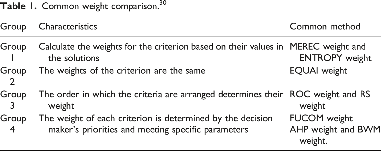
So, with the four weighing method groups shown in Table 1, the features of each method group are extremely varied, and the weights of the criteria vary when determined by different method groups. To have strong trust in the decision outcomes, it should select more than one way of computing the weights. This is the third factor that inspired the authors to conduct this investigation. The MEREC weight technique (first group) was applied in this investigation. This approach is highly accurate and is recommended for use. When used, this strategy produces the same ranking results as the ENTROPY weight method. 31 The EQUAl weight technique was only employed in the second group, thus it was used in this study as well. The third category includes two methods: ROC weight and RS weight. Although they belong to the same group, the weights of the criteria calculated by these two techniques are vastly different. The three approaches in four groups are similar in accuracy. 32 However, the FUCOM weight technique has fewer calculation steps than two other approaches, AHP weight and BWM weight. 33 The PCA approach, which was sensitive to outliers, could also be used to construct predicting and forecasting systems. The Entropy technique may be appropriate for all scenarios needing the MCDM. Robert et al. discovered that the Entropy approach delivers more accuracy than the PCA method. 34 So from the above conclusion ENTROPY weight method is used this study.
Materials and methods
Medical grade UHMWPE(U) was procured from Sigma Aldrich (CAS No. 9002-88-4) with an average molecular weight of 2.5*106 g/mol and a mean particle diameter of about 300 µm. Aluminum Oxide (A) with a molecular weight of 101.96 g/mol and a mean particle size of 20–50 nm was purchased from Adnano Technologies (CAS NO. 1344-28-1). Additionally, Adnano Technologies (CAS NO. 7782-42-5) provided graphene nanoplatelets (G) with a bulk density of 0.1 g/cm3. SEM Images of Al2O3 and Graphene sample as received shown in supportive document by figure S1(a) and S1(b). All the solvents and chemicals used to mix the solution were of analytical grade. The die used for sample preparation is made up of mild steel (MS) prepared using in-house facilities.
Fabrication of nano composite
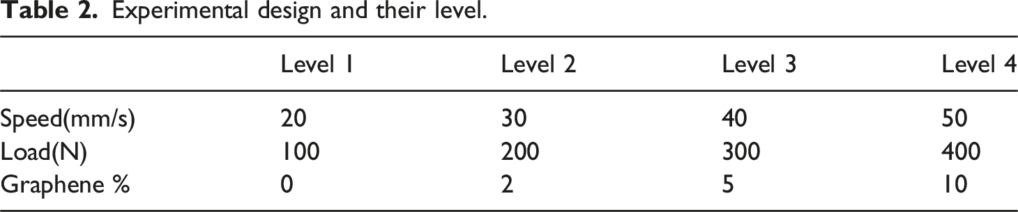
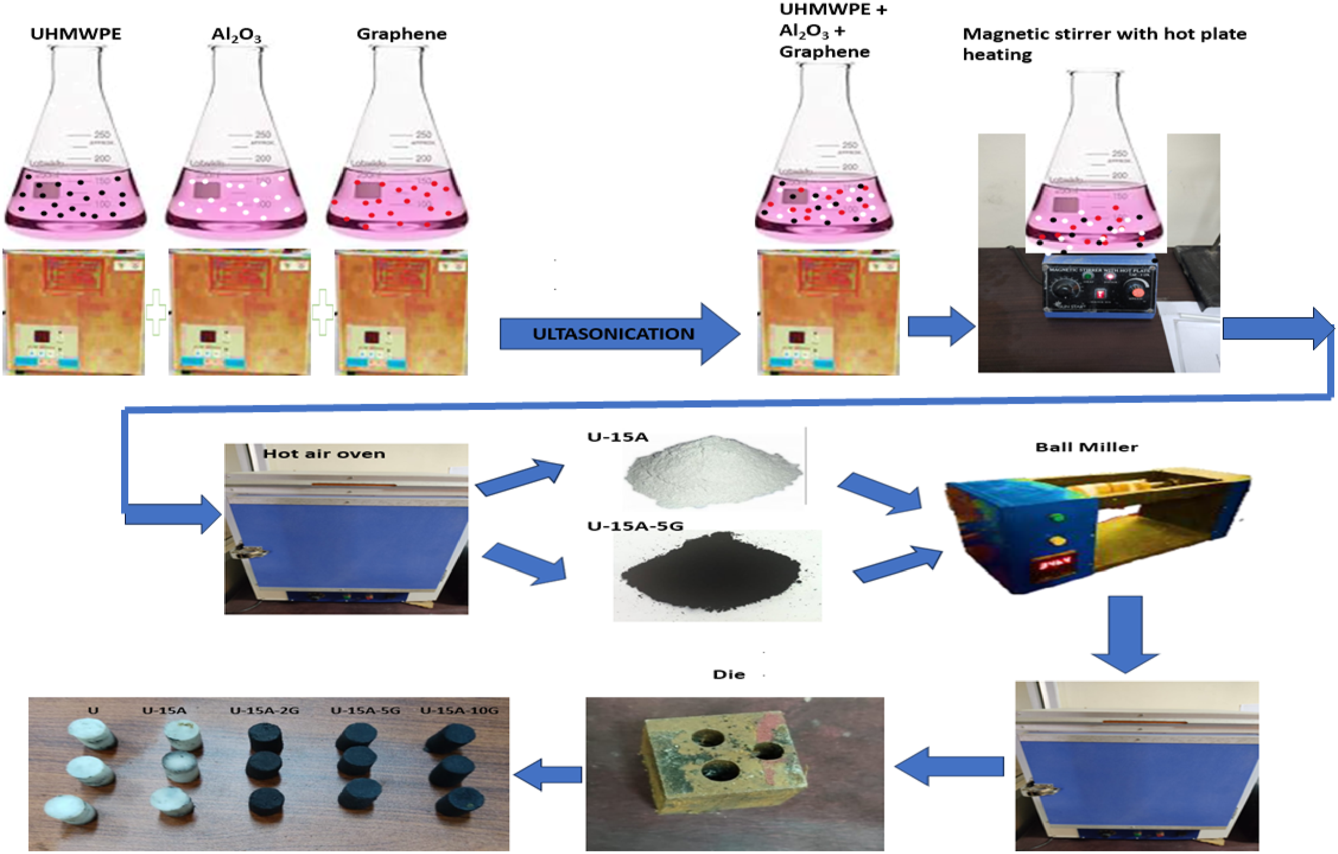
Hybrid nano composite samples were fabricated with varying weight (wt.) percentage of Graphene (i.e. 2, 5 &10%) and fixed wt. percentage of Al2O3 (i.e. 15%) as reinforcement added into the UHMWPE matrix. The first step in developing a hybrid nanocomposite material involves weighing the reinforcing phase and the polymer matrix powder. In order to evaluate how well Graphene and Al2O3 are incorporated into the polymer matrix, various weight percentages of Graphene (2 ,5 & 10 wt%), as well as 15 wt% of Al2O3 , were included in the matrix. After that, a suspension of Graphene and Al2O3 nanoparticles was produced by ultrasonication within 30 mL of acetone for an hour. In order to obtain the final nanocomposite powder with acetone in the liquid phase, the bifiller and acetone combination was first ultrasonicated for an hour before being added to the UHMWPE-50 mL acetone mixture. After that, the mixture was stirred by a mechanical stirrer fitted with a hot plate for 60 min at a temperature of 75°C in order to secure the maximum amount of solvent that should be evaporated. The resultant powder was baked in a hot air oven at 80°C for 5 h to improve solvent extraction. In the end, the powder mixture was ball milled for approximately 2 h to prevent the particles from deforming and to ensure they were properly mixed. In the second phase, the created bio-nanocomposite dry powders were transferred to a mild steel die and then hot-pressed for 1 h at a temperature of 210°C with a pressure of 100 bars. The resultant cylindrical pin-type nanocomposite samples were cooled to room temperature and prepared according to ASTM F732 standard with 13 mm in height and 9-mm diameter samples. SEM images of powder shown in Figure 1. Throughout the procedure, silicon oil was utilized as a lubricant to make removing the composite from the surface of the die as simple as possible. The proposed production procedure method is envisioned as an efficient and cost effective way to develop hybrid nanocomposite materials with desirable properties. The experimental design for three controllable variables with four levels, presented in Table 2. The detailed manufacturing process used for sample development is illustrated in Figure-2. SEM images of composite powder particles. Experimental design and their level. Fabrication procedure of nanocomposite samples for wear test.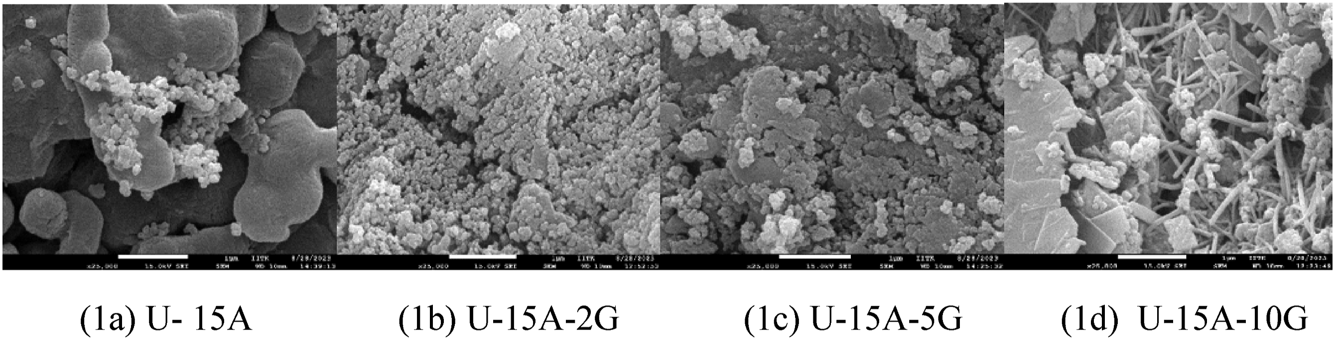
Preparation of SBF
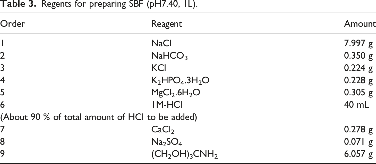
Some implantable materials are considered “bioactive” if they can connect to live bone, establishing a tight and chemically stable contact. This feature, which is inherent in specific glass compositions or may be generated by putting suitable surface treatments to otherwise bio-inert metals, can be tested in vitro by immersion tests in simulated bodily fluid (SBF), which imitate the composition of human plasma. 35
Regents for preparing SBF (pH7.40, 1L).
Densification and hardness of Sample
Composition, densification and hardness of composites.
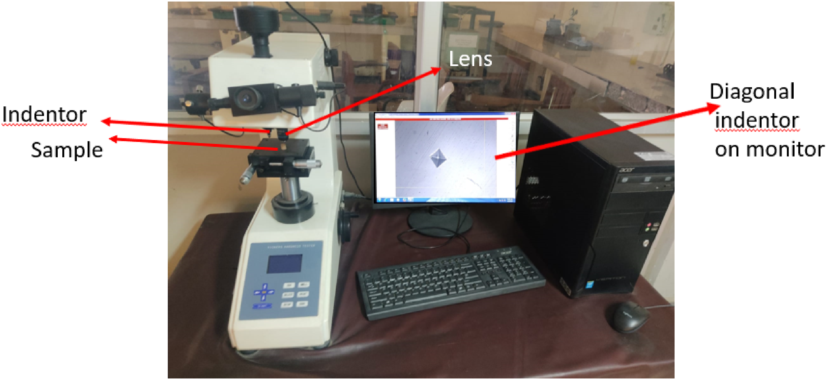
A Vickers micro hardness tester measures the hardness of materials, particularly small or thin samples, by pressing a diamond pyramid indenter (136° between opposite faces) into the material’s surface. The sample is first prepared to be flat and clean, then mounted on the testing stage. A known force is gradually applied and held for a specific duration. After indentation, the diagonal lengths of the indentation are measured under a microscope, and the Vickers hardness number (HV) is calculated from the average of these measurements. Figure 3 shows Vicker Micro hardness tester setup. The Vickers hardness number is calculated using the formula • 𝐹 is the applied force in Newtons. • 𝑑 is the average length of the diagonals of the indentation in milli meters. Vicker micro hardness tester.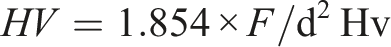
Experimentation
Compression test
The specimens were subjected to a compression test method on ELECTRA 50 Creep testing machine at IIT, Kanpur. By the requirements of the ASTM D695, the dimensions of the specimens were made Three separate runs were conducted for each composition at a 5 mm/min strain rate.The experiment’s technique ensured precision and accuracy as per testing requirements. Figure 4 shows the compression setup Compression setup.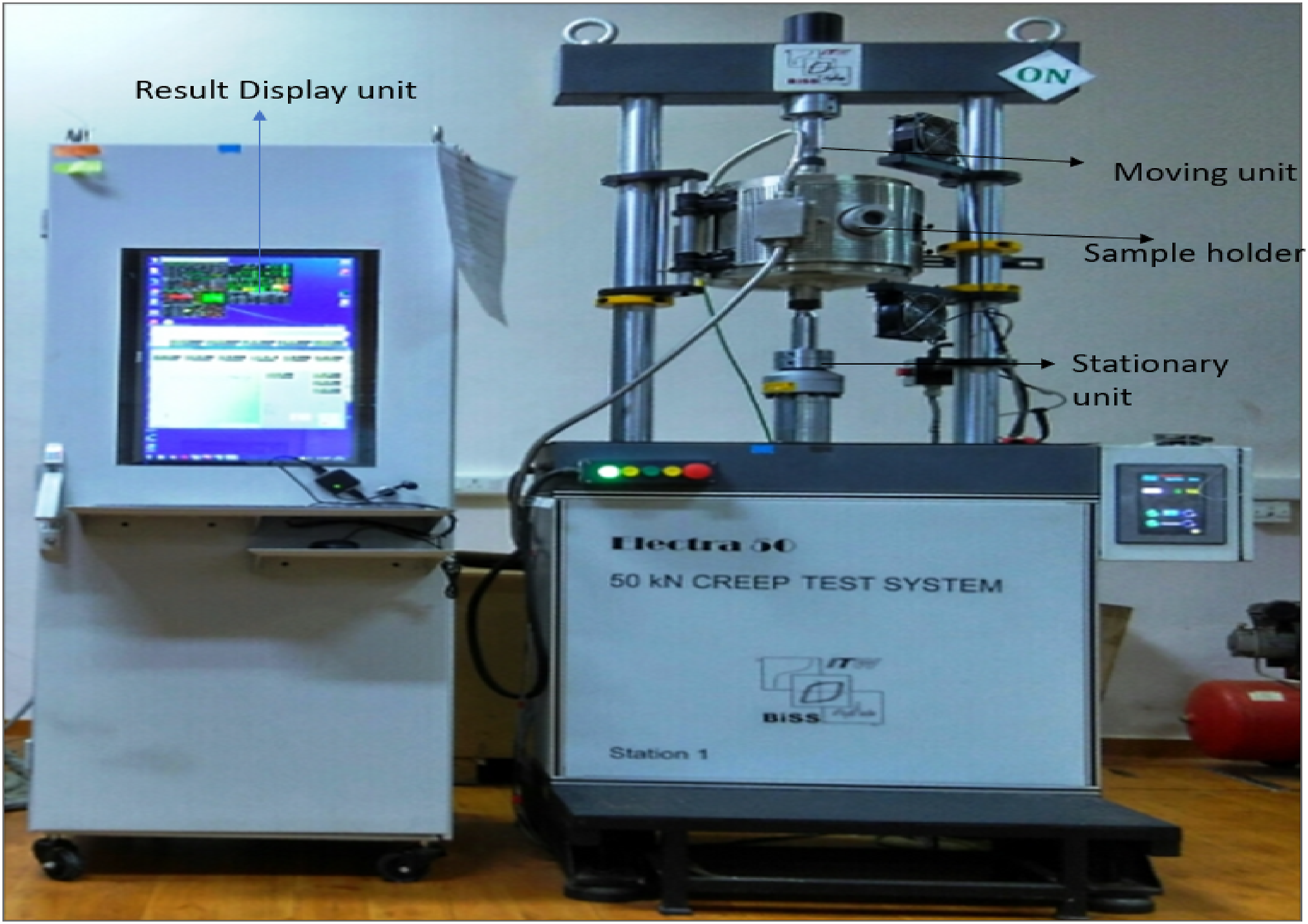
Tribological test
Wear is a surface phenomena in which material degradation occurs from one or both of two solid surfaces in solid-state contact.
37
Wear is determined by the internal resistance of the component to external forces; if the internal structural bonding is strong, it may resist wearing.
38
Figure 5 shows wear tester Bio-tribometer machine setup to measure the wear rate and frictional force. Bio-tribology studies friction, wear, and lubrication in biological systems. The Ducom Bio-tribometer is a precise lab tool used to evaluate the wear of materials, especially for joint prostheses. This tabletop device, with a mechanical unit and integrated electronic controller, is fully automated and operated via Windows-based software, WinDucom. Bio-tribometer components.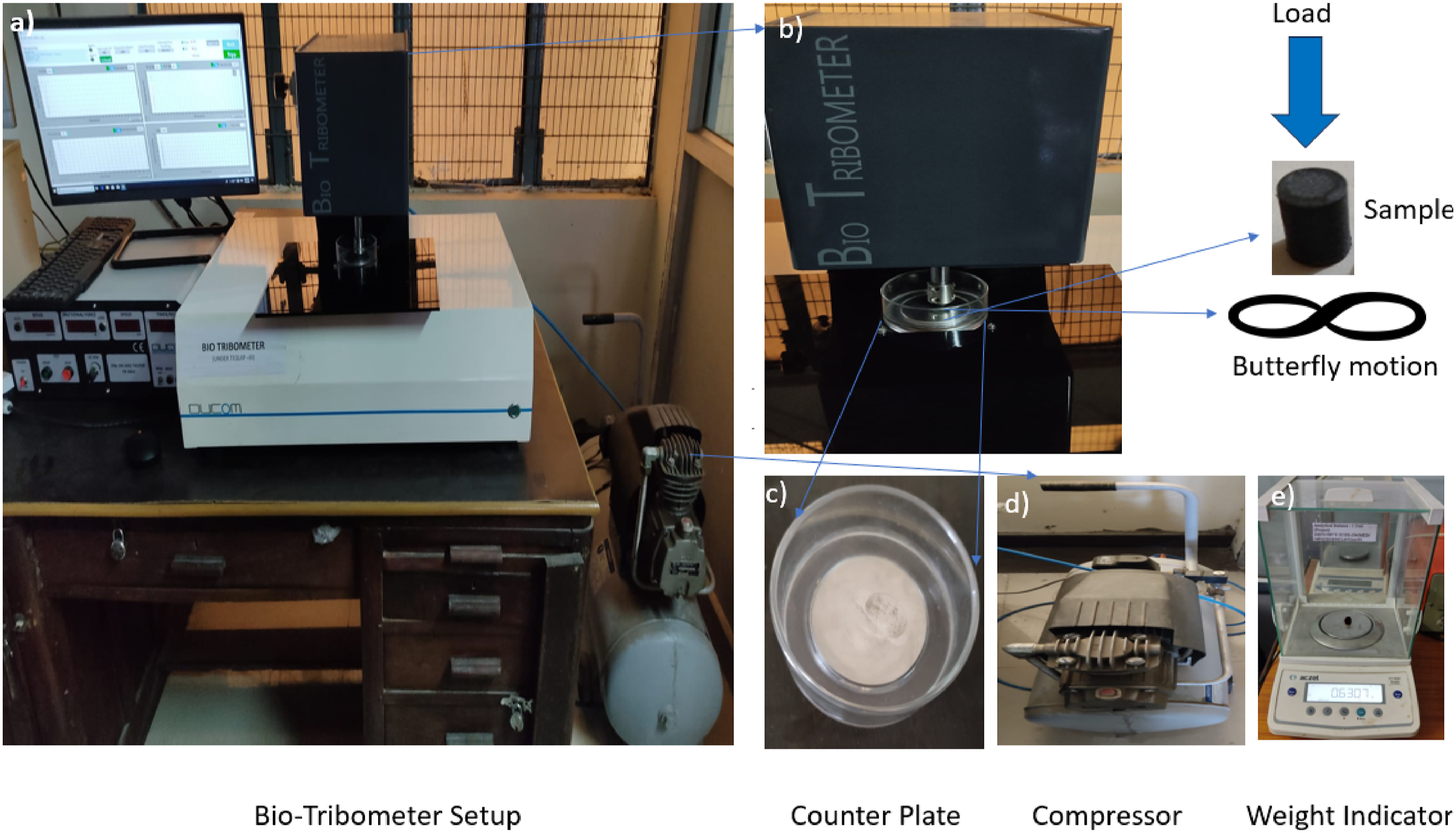
Response surface design
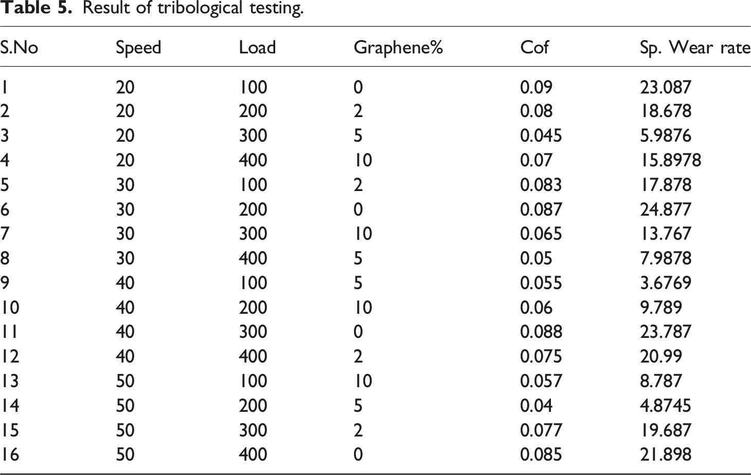
Result of tribological testing.
Weight determination
Entropy can be used in information theory to quantify a system’s disorganisation. When applying the idea of entropy to weight measurement, a characteristic with high entropy indicates that there is a wide variety of possible answers, which suggests that the attribute has a greater overall impact on the response.
39
Wen et al.
40
proposed the mapping function i.e. fi = [0,1]→[0,1] which is used in entropy, which should satisfy the three conditions: 1) fi(0) = 0; 2) fi(x) = fi(1 – x); and 3) fi(x) is increasing in the range of x Є(0,0.5). Thus, this function we(x) is used as mapping function in the entropy measurement as shown in equation (1):
At x = 0.5, this function reaches its maximum value, and the value e.5– 1 = 0.65. To allow mapping to provide results in the [0,1] range, Wen at al.
41
defined new entropy as by Equation (2)
According to Ref. 42’s recommended method for calculating the weights of each attribute,
Step 3.1 Project results are obtained by normalising the decision matrix arrays (performance indices) using equation (3).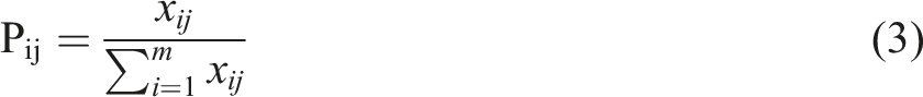
Step 3.2. Equation (4) is used to compute the entropy measurement of project results:
Step 3.3. Using equation (5) to define the objective weight based on the entropy concept: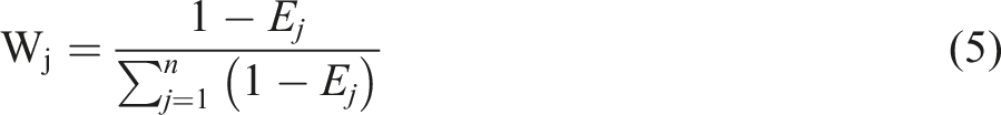
The result of multiplying the grey connection coefficient by the appropriate weight of each response characteristic is then added to determine the grey relational grade, which is provided by equation (6),
43
:
The number of observations for each sequence in the current research, m, is equal to 16, and the number of responses, n, is equal to 2.
Emperical model development and parametric optimization
The proposed method is based on a combined simple additive weighting and exponentially weighted product model. It might be a collection of compromise solutions. To answer a CoCoSo decision issue, after defining the options and relevant criteria, the following stages are validated:
44
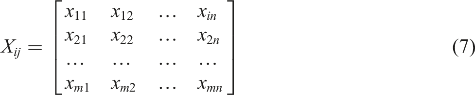
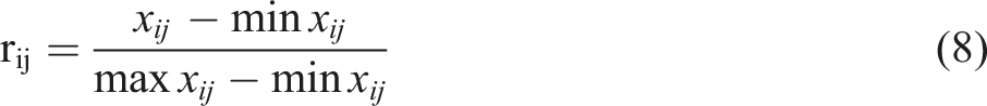
(1) The initial decision-making matrix is determined as shown below: (2) The normalization of the values for the benefit criterion (8) and for the cost criterion (9) are determined as follows (3) The sum of the weighted comparability sequence and the total of the power weight of comparability sequences for each alternative are represented by Si (equation (10)) and Pi (equation (11)), respectively:


this Si value is achieved based on grey relational generation approach:
this Pi value is also achieved according to the WASPAS multiplicative attitude. (4) Calculate the relative weights of options using the following aggregation procedures. In this stage, three appraisal score procedures are employed to determine relative weights of other options, which are derived using Formulas (12)–(14)
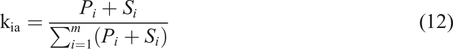
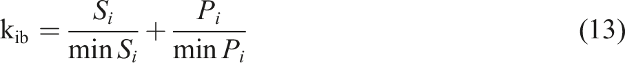

Equation (12) is regarded as the arithmetic mean of sums of WSM and WPM scores, whereas equation (13) reflects a total of relative WSM and WPM scores in comparison to the best. Equation (13) yields a balanced compromise of WSM and WPM model scores. In equation (13), decision-makers select λ (typically λ = 0.5). However, the suggested CoCoSo’s flexibility and stability can be based on different parameters. (5) The ultimate ranking of the options is established based on ki values (the more important, the better).

Invitro analysis
The U-15A-5G sample was cut into discs with diameters of 5 mm and thicknesses of 0.26 mm, rinsed with ethanol and ultra-high filtered water, and dried overnight at room temperature. The dried samples were submerged in 10 mM NaOH solutions for 48 h. The NaOH-treated samples were then washed, immersed in 1.5 SBF, and incubated at 37°C for 18 days. The samples were agitated every day. The SBF was updated every three days to ensure that the samples had fresh SBF. After being withdrawn from the SBF, the samples were air-dried at 37°C overnight. Before the FTIR analysis, the items were maintained in closed containers at room temperature.
Results and discussion
This section presents a complete analysis of the findings obtained from the compression and tribological tests carried out on UHMWPE with varying weight percentages of filler loadings. The tests were performed under different loading and sliding conditions to evaluate the mechanical and sliding properties of the material.
Compression test
Compressive strength and modulus values of composite samples.
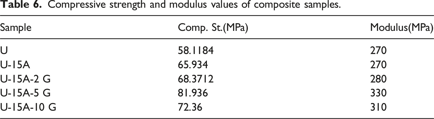
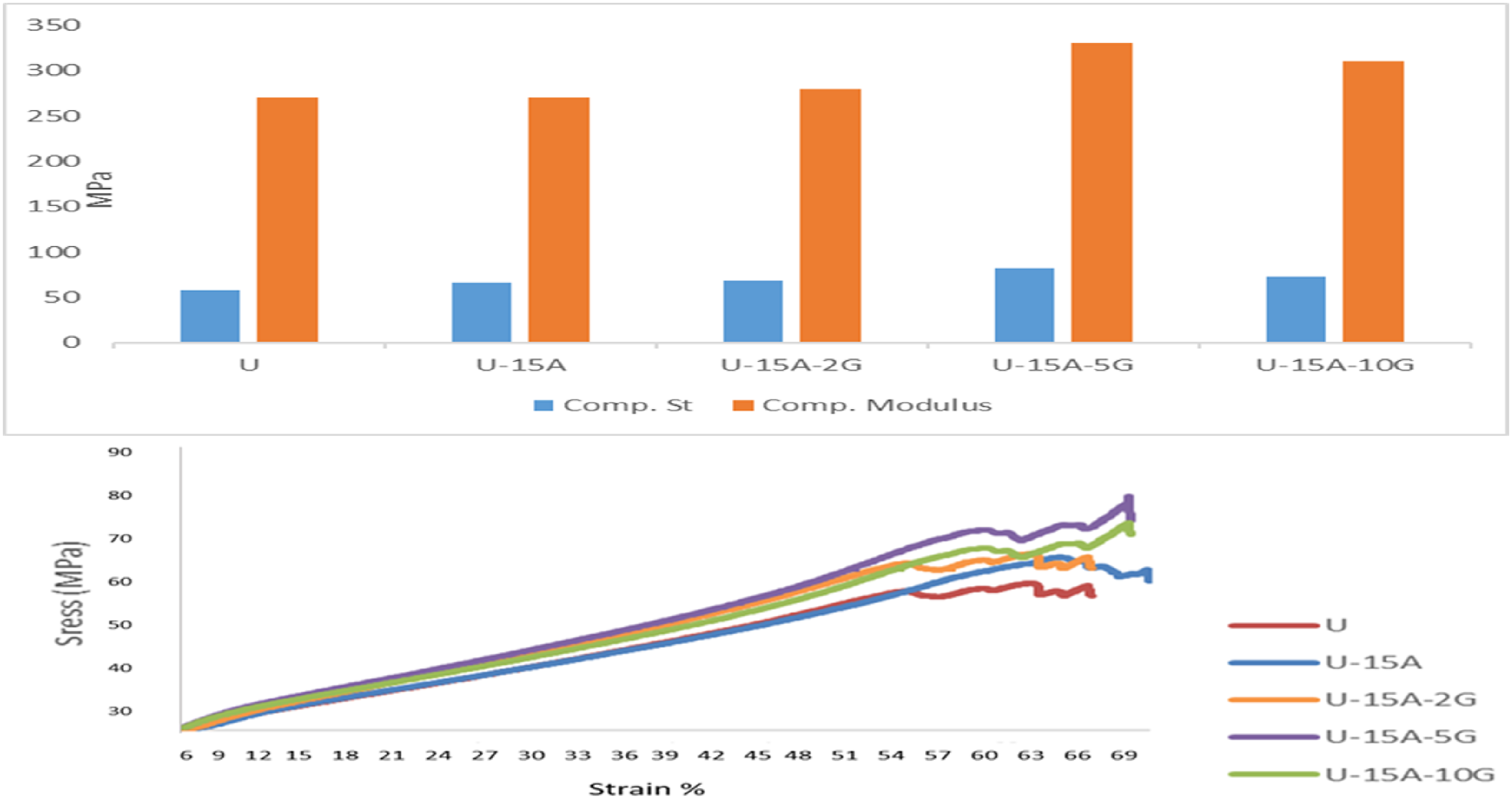
Compressive strength and modulus.
The composite U-15A-5 G has a compressive modulus of 330 MPa, which is the highest and 22.22% higher than neat UHMWPE’s compressive modulus of 270 MPa. Adding 15% Aluminium oxide and 5% Graphene nanoparticles to UHMWPE composition enhances its compressive strength. The main reason for the increment in compression strength is due to Aluminium oxide and Graphene nanoparticles are significantly stronger than UHMWPE; therefore, composites including Aluminium oxide and Graphene strengthen UHMWPE, Hydroxyapatite, a hard material, was incorporated into UHMWPE to enhance its mechanical properties, as previously reported by J. Crowley. 46 Aluminium oxide and Graphene nanoparticles reinforcing particles in a polymer matrix can obstruct the mobility of the UHMWPE molecular chain, increasing compression strength. As a result, the introduction of fillers into the UHMWPE matrix improves compression characteristics. Similar result shown by Hanna et.al. 47 Ceramic-filled polymer matrix composites have gained significant attention for biomedical applications due to their enhanced properties. Studies have investigated the effects of various ceramic fillers on polymer matrices, particularly unsaturated polyester resin. as the compressive stress increases, the nanofillers work to create additional paths that the stress must navigate through before causing the material to fail. This bridging effect effectively increases the distance that the crack must travel through the material before it can cause catastrophic failure. As a result, the overall compression resistance of the material is improved. 48
The material’s compressive strength is decreased when nano filler Graphene is more than 5%. This is because the degree of cross-linking is restricted, which leads to higher agglomeration of the fillers and matrix. 49
Tribological study
Tribological findings of the developed nanocomposite samples are discussed in this section. A total of 16 experiments have been conducted on various samples with different bifiller compositions. Table 4 shows the experimental findings of Specific wear rate and Coefficient of friction based on the used design parameters. The filler content of Graphene considered for the experiments is 2%, 5%, 10% and that of Aluminium Oxide is 15 wt%.
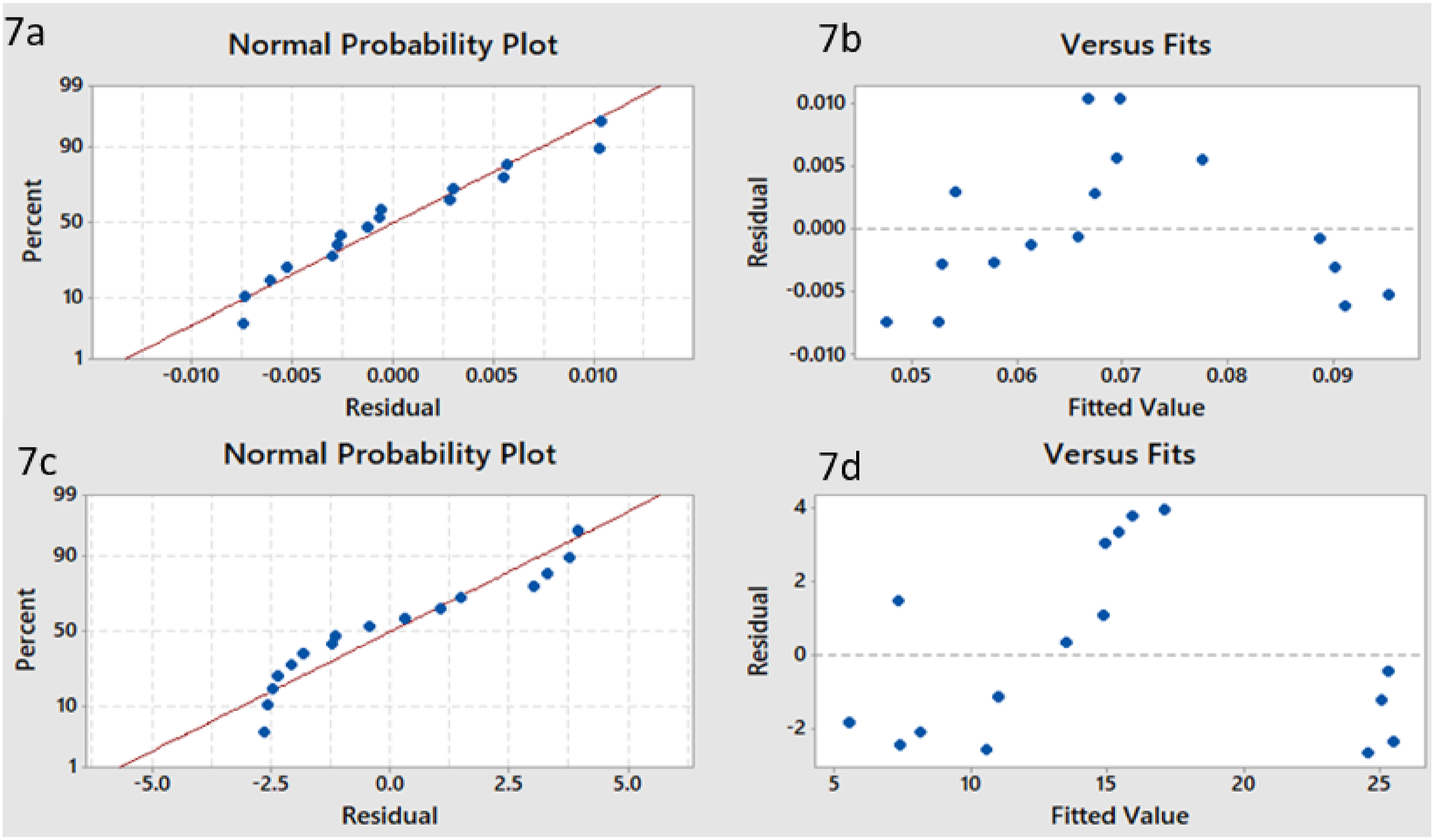
The results of the empirical model and regression analysis on the tribological properties of UHMWPE reinforced with aluminium oxide and Graphenedemonstrate that the model residuals for the UHMWPE wear rate are normally distributed. The observed linearity in the normal probability plot (Figure 7(a)) as well as the even distribution of the data versus the fits (Figure 7(b)) support this. (Figure 7(c)) shows the normal probability plot for SpWr rate and data versus fit shown in (Figure 7(d)). These results show that the model is reliable and may be used to accurately forecast the wear rate of UHMWPE and its composites. As a result, the confirmation of normal residual distribution in this research signifies the validity of the empirical model and regression analysis. Overall, our results show that UHMWPE reinforced with aluminium oxide and Graphene composites can potentially be a material with favorable tribological characteristics. Tables S1 and S2 given in supporting information show the analysis of variance (ANOVA) and regression coefficient of the UHMWPE composites reinforced with aluminium oxide and Graphene for coefficient of friction (CoF) and Specific wear rate. The probability (p-value) for coefficient of friction (CoF) and Specific wear rate the was 0.036 and 0.028, respectively. Both p-values were less than 0.05, which means that the model developed for the tribological study is satisfactory. The R2 values (both for friction and SpWr models), which was over 87%, were significant. Equations (16) and (17) were used to develop a model for theCoF and SpWr rate, respectively. The equations use coded units for filler content speed, load and Graphene%. Shanon entropy weight comes out to be 0.493586556 and 0.506413444 for Cof and wear respectively. Residual plot for Cof and wear.


In Table S1 given in supporting document, the T-values and p-values demonstrate the influence of each input variable on the CoF models. A smaller p-value and a larger T-value suggest a more vital link between the regression coefficient and the input variable. The Graphene content is the most crucial factor. The interaction between speed and load, Speed and Graphene, Load and graphene are less significant. Table S2 given in supporting document shows that the Sp. Wr. rate model implies that the relationship between graphene content has the most effect on the predicted regression coefficient of friction. On the other hand, the quadratic load, the interaction between the load and the speed are less significant.
Effect of Cof on parameters
The impact of process factors on the coefficient of friction is shown in Figure 8. Due to the shearing action between the disc and specimen, the coefficient of friction between the polymer specimen pin and the disc lowers as the sliding contact speed increases. At the interface, a small layer of polymer debris accumulates, and frictional contact occurs at the accumulated debris. Because of polymer debris at the contact, the friction attained a steady state after a specified number of rotations. As a result, as already reported, the COF decreases with an increase in rotational speed.
50
Main effect plot for Cof.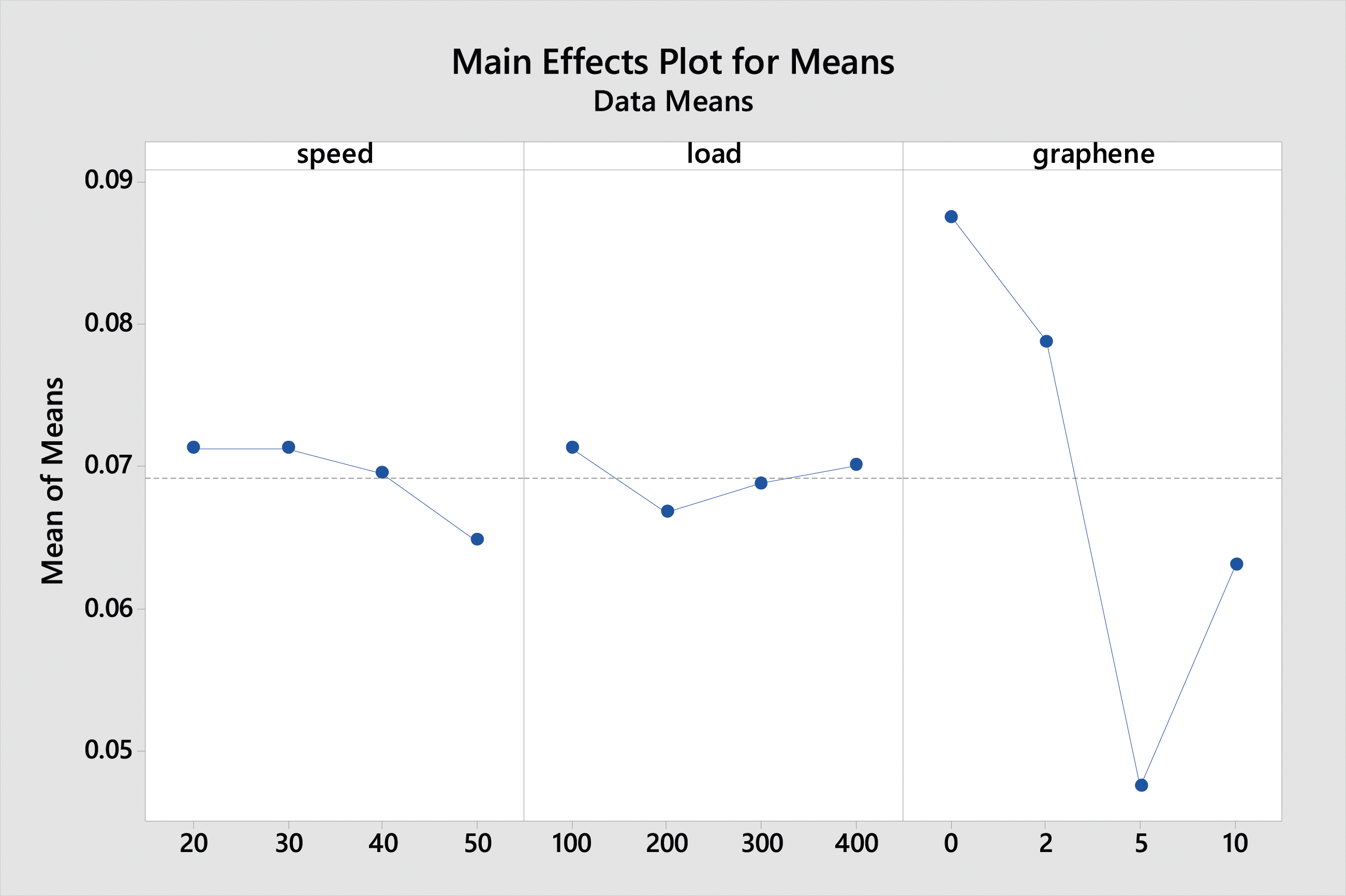
For certain types of polymers, particularly those that exhibit viscoelastic behaviour, an increase in load can indeed lead to a decrease in the coefficient of friction. This behaviour is often observed in polymers with high molecular weight and long polymer chains. When a load is applied to a polymer surface, the polymer chains may align in the direction of the applied force. This alignment can reduce the entanglement and intermolecular interactions between polymer chains, leading to decreased friction. Under higher loads, polymers may experience less deformation because they are already experiencing significant deformation at lower loads. This reduced deformation can result in lower frictional forces between the contacting surfaces. In polymers, especially those with long chains, molecular segments can slide past each other under load. This slippage between polymer chains can reduce the resistance to motion between the contacting surfaces, leading to lower friction. Polymers often exhibit viscoelastic behaviour, meaning they possess both viscous (flow-like) and elastic (reversible deformation) properties. Under increasing load, polymers may exhibit more pronounced viscoelastic effects, such as creep and stress relaxation, which can reduce friction. Some polymers can undergo changes in their mechanical properties, including friction, with changes in temperature. Increasing load may induce temperature rises in the contacting surfaces, altering the frictional behavior of the polymer. 51 One possible cause of inefficient force transmission from the soft polymer to the rigid nano- bifiller is the increased agglomeration of the bifillers. 52 Also, Figure S2 given in supporting document clearly shows the good dispersion of bifiller within the polymer matrix.
During sliding, the UHMWPE surface that comes into touch with the hard asperities of the counterface loses material, which is subsequently thrown away as wear debris. When accumulated worn debris accumulated, adhesive wear happens. A transfer film forms on the other surface following many movements. Finding match with Hussain et. al. that the presence of human serum lubricant led to the formation of a protective film on the surface of the composite pins, improving their wear resistance compared to dry sliding conditions. The use of alumina nanopowder reduced the wear of UHMWPE-based composites under human serum lubrication. 53 Over the course of application, this transfer film development stops further deterioration of the composite surface. therefore supporting implants that endure. Upto 5% Graphene, Coefficient of friction decreases and increases above this, The degree of cross-linking is constrained, which leads to higher agglomeration of the fillers and matrix. 49
Effect of wear rate on variables
The impact of process factors on the wear is shown in Figure 9. The relationship between speed and wear is complex and varies depending on the material and conditions. Saka (1977)
54
found that the wear rate of certain metals initially decreases with speed, but then increases again. Berman (2013)
55
observed a significant reduction in wear and friction on steel surfaces when covered with graphene layers, even at high speeds. Dressler (2011)
56
noted a decrease in wear rate in polyethylene following a change in sliding direction. Barrett (1992)
57
discovered that the wear of ultra-high molecular weight polyethylene is influenced by surface temperature and roughness, with an optimum roughness for minimal wear at low and medium speeds. Main effect plot for wear.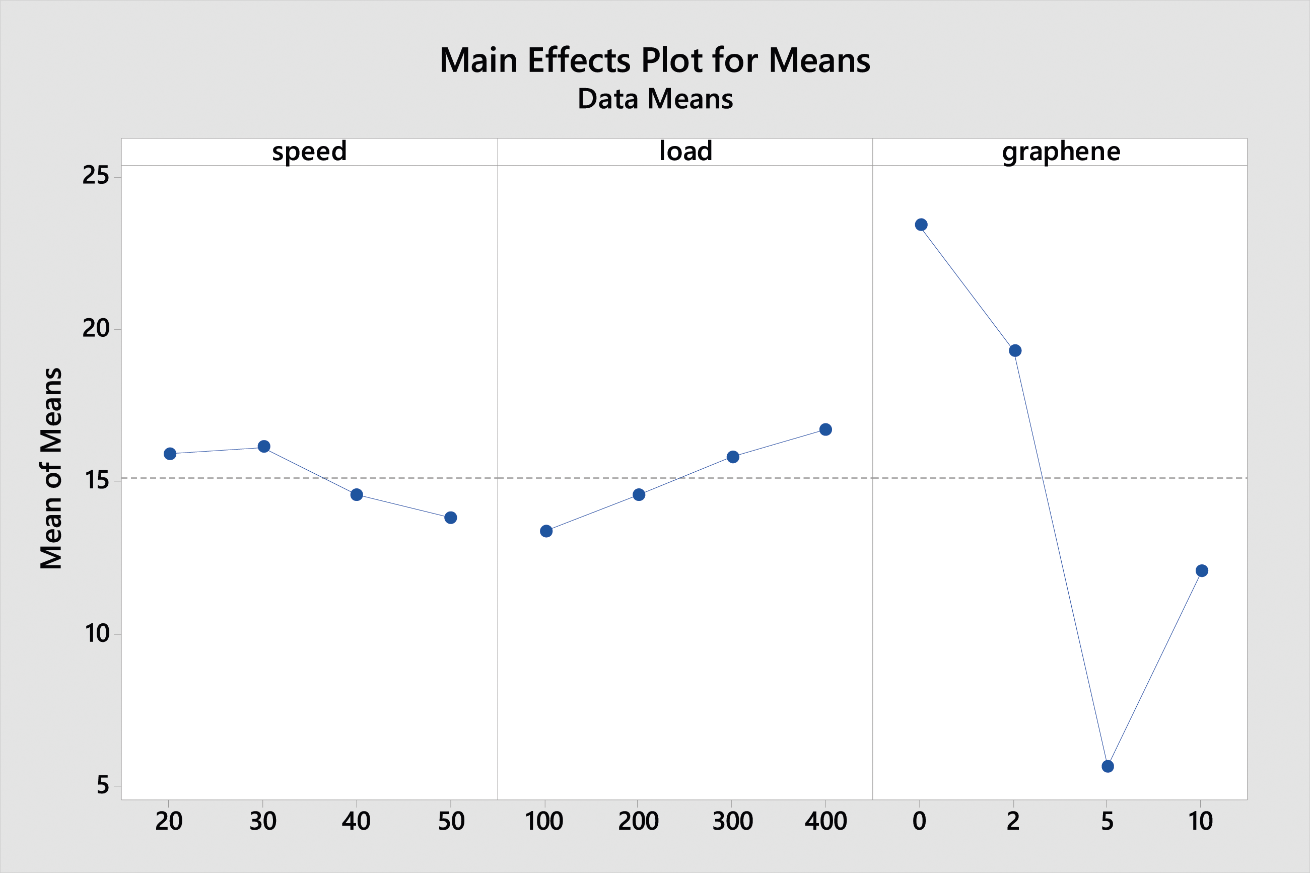
Due to the high flash temperatures obtained, the tribological behaviour may be an easier occurrence of plastic flow caused on by a reduction in shear strength in a specimen contact region or by local melting. The time available for heat dissipation is limited, especially in the hot-spots, at high speeds because the duration between passes of the cylindrical specimen over a similar region of the disc is reduced. A second aspect that may be influencing tribological behaviour under these conditions is that debris formed at low speeds is not expelled from the worn track and so continues to contribute to the track wear process in the form of abrasive wear, Finding matches with Dougherty et al. that on increasing load wear also increases. 58
The degree of shear stress that causes plastic flow increases with increasing load. Consequently, more material is moved as a result. With the load, the tensile stress will likewise increase. It favours cracking and causes the specimen to fracture at greater rates. It is also anticipated that when the load increases, the abrasive impact of the worn debris would do likewise. as the debris will encroach more inside the specimen. Therefore, when load increases, specific wear rate likewise rises as suggested by G. ferron et. al. 59
Discussion on the optimal parametric settings
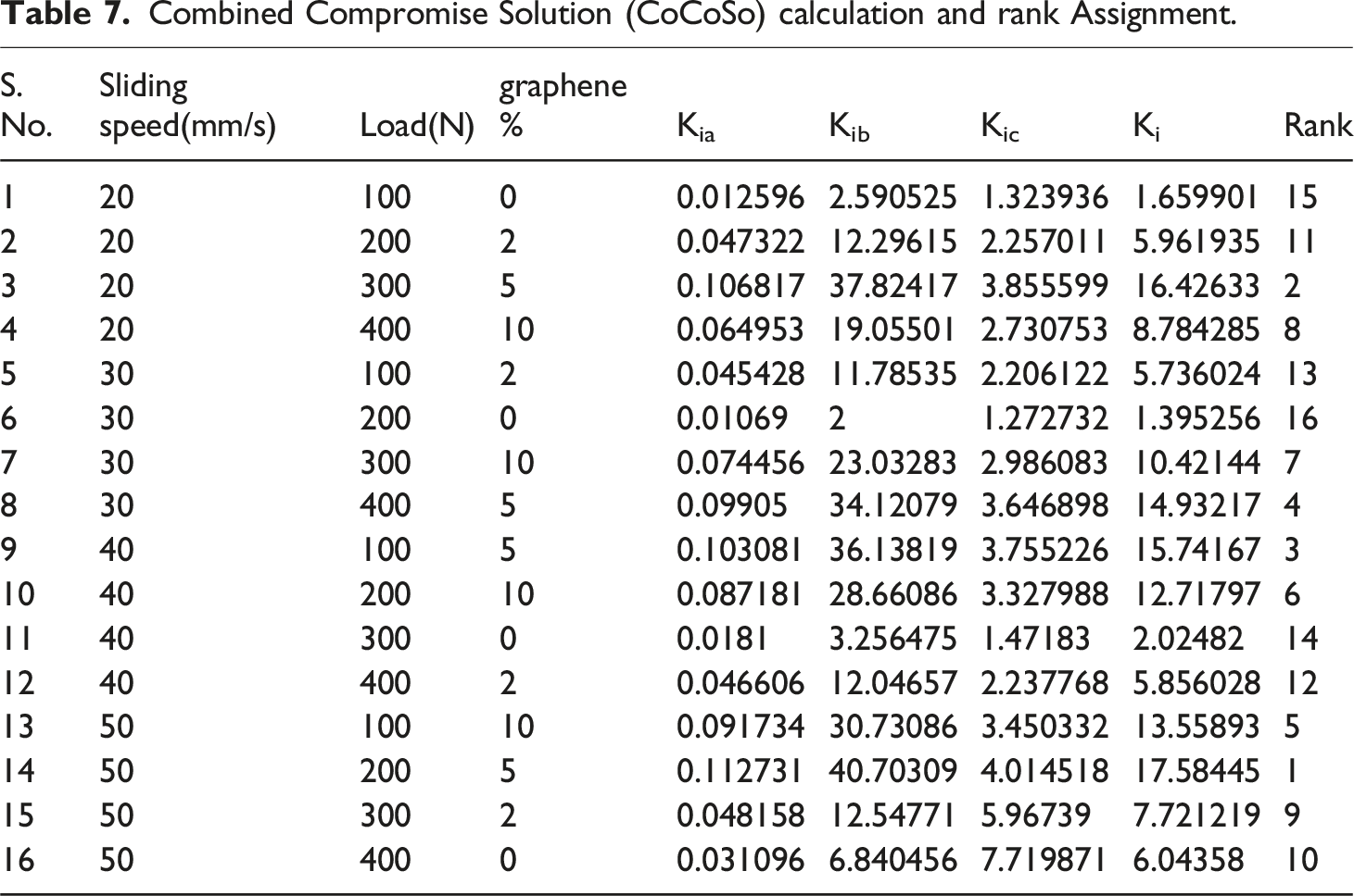
Combined Compromise Solution (CoCoSo) calculation and rank Assignment.
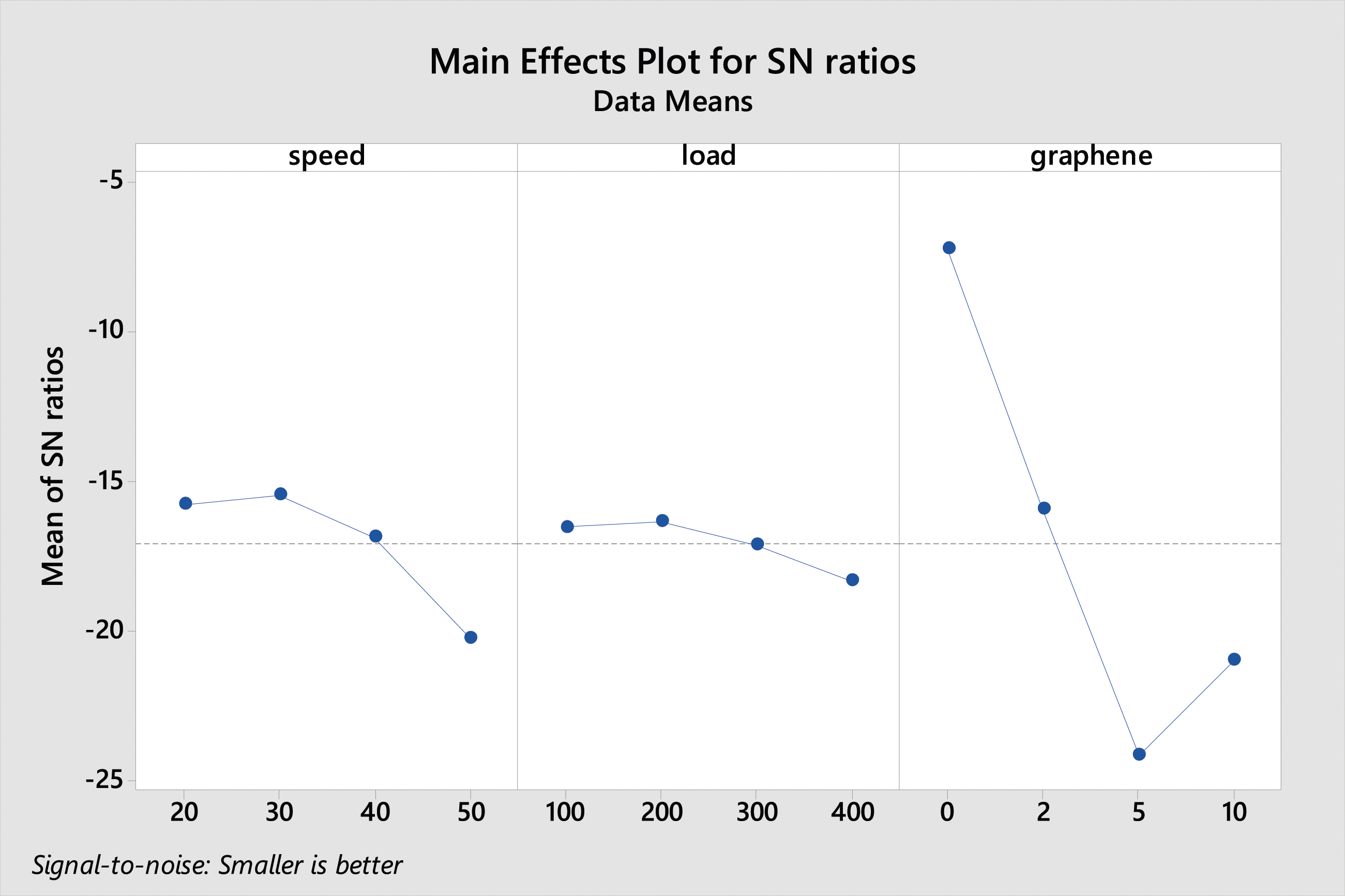
Main effect plot for CoCoSo.
The sliding motion of the graphene interlayer also contributes to the increased wear resistance of the polymeric composites. The self-lubrication property of graphene is largely due to the automatically smooth surface and the weak van der Waals force between its layers, which facilitates interlayer sliding. 60 When a metal surface rubs against a polymer, the softer material transfer onto the harder surface, creating a protective coating on the metal surface. With the presence of the graphene interlayer, this effect is further enhanced, forming a protective tribo layer that shields the polymer from the harsher parts of the counter surface. As a result, the wear mostly occurs through “like-on-like” sliding pairs, leading to reduced adhesive wear. 61
The optical microscopic analysis of the wear surface on the optimal condition are illustrated in Figure 11(a), whereas Figure 11(b) shows the most wear sample. It has been conclusively determined that during experiment number 14, the sample containing UHMWPE reinforced with15% Al2O3, 5% graphene fillers exhibited the lowest amount of wear. The combination of these fillers at specific weight percentages enhances load transfer between the soft polymer and graphene. Graphene’s high specific surface area and two-dimensional structure contribute to load transfer. Similar effects were observed in polyimide nanocomposites reinforced with rGO and Zirconia Oxide (ZrO2). Additionally, graphene’s high thermal conductivity and mechanical properties are beneficial for tribology applications in polymer nanocomposites.60,62,63 SEM images of (a) least and (b) most worn out sample surfaces during tribo testing.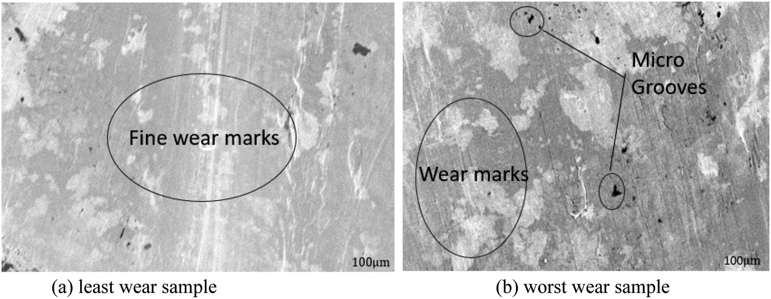
The combination of UHMWPE with graphene and aluminium oxide has shown promising results in tribological applications. Tai et al. 64 and Hu et al. 65 both found that the addition of graphene oxide (GO) to UHMWPE significantly improved hardness and wear resistance, with the latter also noting a reduction in friction coefficient. Aliyu et al. 66 further demonstrated the effectiveness of UHMWPE reinforced with graphene nanoplatelets (GNPs) in reducing friction and wear in dry and boundary lubrication conditions. Martínez-Morlanes 67 also reported a reduction in wear rate and friction coefficient with the addition of GNPs to UHMWPE, particularly at lower concentrations. These findings collectively suggest that the combination of UHMWPE with graphene and aluminium oxide could indeed be a strong candidate for tribological applications.
In-vitro analysis
As indicated in Figure 12. Peaks from the U-15A-5 G are seen at 2919 and 2848 cm−1. These bands correspond to asymmetric and symmetric CH2 stretching vibrations, respectively, whilst the characteristics at 1469 and 718 cm−1 are attributable to C-H bending and rocking deformations, and the stretching of O-Al-O occurs at 1000 cm−1. SBF-treated U-15A-5 G samples reveal, in addition to the polyethylene peaks at 1029 and 1439 cm−1, which we ascribed to structural P-O bonds of the phosphate groups and CO3 absorption in precipitated apatite repectively
68
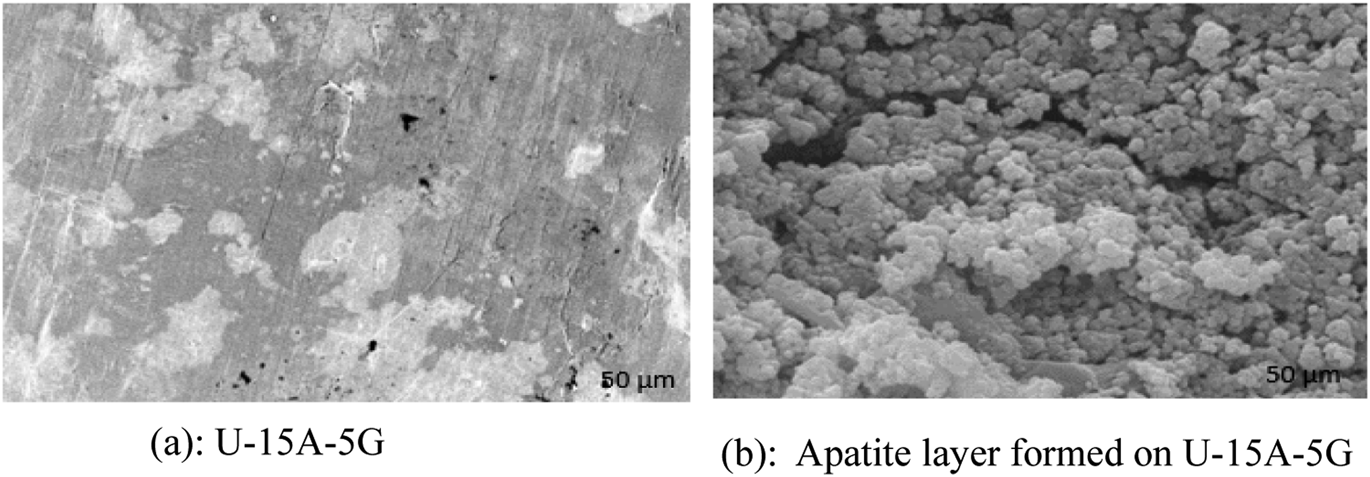
The apatite layer contains phosphate and carbonate ions, indicating potential for high in vitro bioactivity on polymeric films. As demonstrated in Figure 13, an apatite layer forms during in vitro testing, indicating the bioactivity of coatings. FTIR of untreated U-15A-5 G sample and treated U-15A-5 G sample with 5 M NaOH after immersion in SBF for 18 days. SEM images of (a) before treated U-15A-5G, (b) after treated, apatite layer formed on U-15A-5G.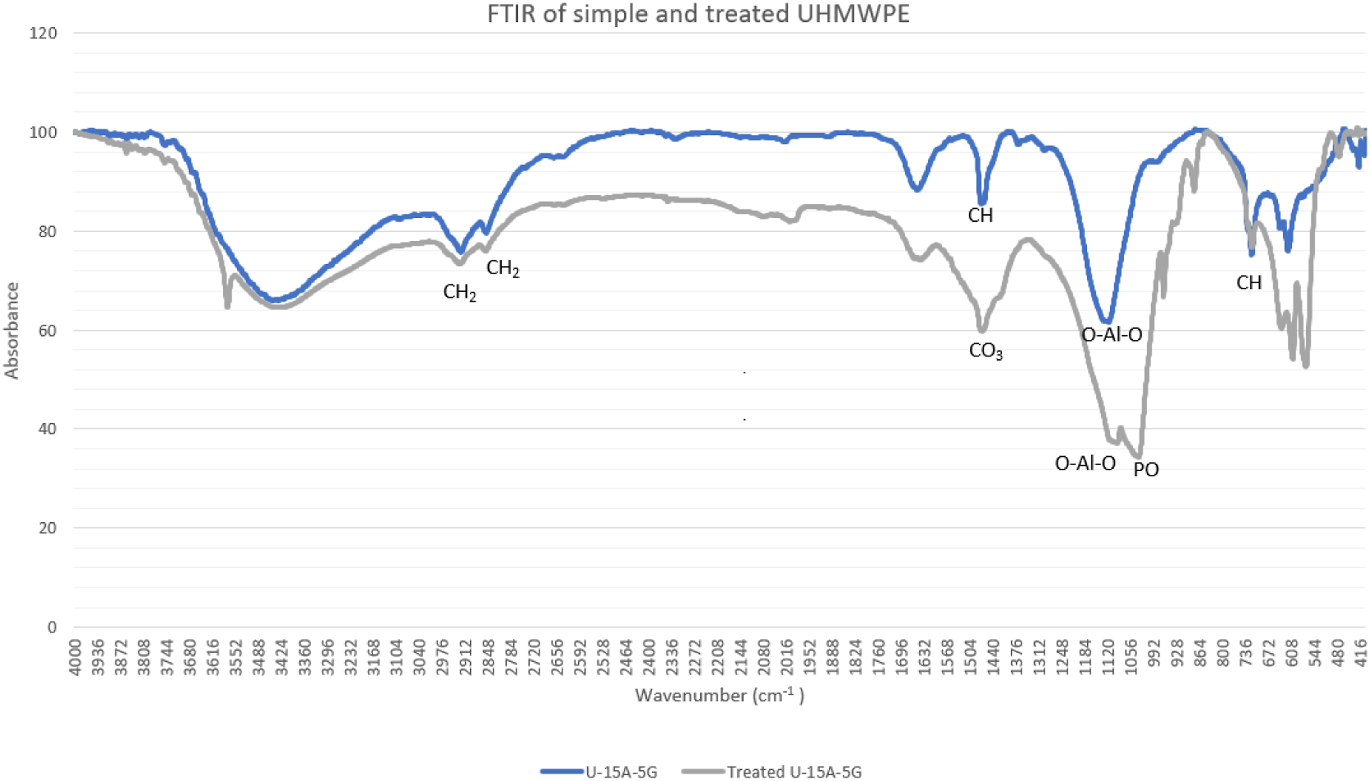
Conclusion
In order to alter the biofunctional, mechanical, and tribological performance of the UHMWPE-based hip implant, Al2O3 and graphene were used in tandem as reinforcements in this work. In addition, final nanocomposite samples were prepared using a simple method that included ultrasonication, solvent mixing, and compression molding. The impact of control factors like speed, load and Graphene % on the wear rate (Wr) and coefficient of friction (Cof) of UHMWPE and its reinforced composite was also investigated. According to the results, the developed composite shows better compressive strength than the neat UHMWPE. It is concluded from the investigation that altering the values of these control parameters has a substantial impact on the Cof and the Wear. Consequently, it is essential to carefully consider and maintain control over these characteristics when choosing UHMWPE for use in applications that need strong wear resistance and low Cof. Overall, findings add to a better knowledge and favorable tribological behaviors of UHMWPE. Following are the conclusions that can be drawn from the obtained results.
The study found that the mechanical characteristics of 15% Al2O3 and 5 wt% graphene incorporated UHMWPE were better than pristine UHMWPE. In particular, the compression strength of the U-15A-5 G material was about 81.936 MPa, which was 40.9% better than the pure UHMWPE. Also, the compression modulus is about 330 MPa which is 22.2% higher than neat UHMWPE. Control parameters such as speed, load and Graphene% has effect on Cof and wear. The Cof depends on load, graphene and graphene interaction, the wear depends on load, graphene and graphene interaction. In the examined range for UHMWPE, it was found that a nanofiller loading of 15% Al2O3 and 5 wt% graphene, at an applied load of 200N, and a speed of 50 mm/s were the ideal sliding conditions for minimizing wear and the Cof. The worn surfaces were examined under an optical microscope, which revealed that the surface of the UHMWPE with nanofiller was smoother than the surface of the UHMWPE without bifiller nanoparticles.
After immersion in 1.5 SBF, a bioactive apatite layer formed on UHMWPE nano composite films in a short amount of time. Phosphate and carbonate ions were present in the apatite layer, indicating perhaps high in vitro bioactivity on polymeric film.
Based on the fact that Al2O3 and graphene has excellent tribological and wear properties. It is anticipated that Graphene, Aluminium oxide, UHMWPE composites will be appealing for use as artificial bearing material in prosthesis components for complete joint replacements of the hip and knee. Other nanomaterials, such as MWCNTs, CNTs, rGO,GO and so on, can be studied further to determine their effects on polymer materials, specifically UHMWPE.
Supplemental Material
Supplemental Material - Optimization through combined compromise solution and weight determination through SHANNON-ENTROPY for multi criteria decision making in tribological testing of ultrahigh molecular weight polyethylene nano-composite in SBF environment and compression testing with it’s invitro analysis
Supplemental Material for Optimization through combined compromise solution and weight determination through SHANNON-ENTROPY for multi criteria decision making in tribological testing of ultrahigh molecular weight polyethylene nano-composite in SBF environment and compression testing with it’s invitro analysis by Parijat Srivastava and Vinay Pratap Singh in Journal of Thermoplastic Composite Materials
Footnotes
Declaration of conflicting interests
The author(s) declared no potential conflicts of interest with respect to the research, authorship, and/or publication of this article.
Funding
The author(s) received no financial support for the research, authorship, and/or publication of this article.
Supplemental Material
Supplemental material for this article is available online.
References
Supplementary Material
Please find the following supplemental material available below.
For Open Access articles published under a Creative Commons License, all supplemental material carries the same license as the article it is associated with.
For non-Open Access articles published, all supplemental material carries a non-exclusive license, and permission requests for re-use of supplemental material or any part of supplemental material shall be sent directly to the copyright owner as specified in the copyright notice associated with the article.