
Abstract
Aluminium and its alloys have gained increasing importance in structural engineering due to advantageous properties such as light weight, ease of machining and corrosion resistance. This article presents surface-related challenges facing aluminium welding, specifically weld process limitations and joint limitations. The methodological approach is a critical review of published literature and results based on eight industrial welding processes for aluminium and six joint types. It is shown that challenges such as heat input control, hot cracking, porosity and weldable thickness vary with the process used and that there is no optimal general weld process for all aluminium alloys and thicknesses. A selection table is presented to assist in selection of the optimal process for specific applications. This study illustrates that knowledge of weld limitations is valuable in selection of appropriate weld processes.
Introduction
Aluminium and its alloys are widely used in welding industries due to economic advantages such as light weight, good corrosion resistance, high toughness, extreme temperature capabilities and easy recyclability. 1 Aluminium alloys are used for construction of airplanes, cars, rail coaches and marine transports. Aluminium alloys are used in manufacture of tanks and pressure vessels because of their high specific strength, good heat conductivity and beneficial properties at low temperatures. 2 Aluminium is the second most used metal after iron and steel in the industry; for example, aluminium is the second most used material taking about 15% of total body weight of average cars and about 34% in Audi A2. 3 There are comprehensive reviews on the uses and applications of aluminium and its alloys.4,5 Welding is a means of joining metals by creating coalescence due to heat. The work piece is melted at the joint point (weld pool) that solidifies on cooling. Welding of aluminium alloys is important for fabricating structural constructions and mechanical fabrications like aircrafts. However, welding has problems and can be challenging. Welding defects common to aluminium include porosity, hot cracking, incomplete fusion and so on.2,6
Researches7,8 have shown that welding aluminium demands greater caution compared with steel, particularly as regards the amount of heat input and pre-weld cleaning, and that acceptable weld processes for aluminium joints are limited because the weldable thickness varies considerably with the different welding processes. It is therefore of interest to study the limitations facing aluminium welding, particularly joint- and process-specific limitations.
The aim of this article is to present a comprehensive guide to understanding aluminium-welding challenges. In the field of aluminium welding, there are eight industrially common welding processes and six basic joint types that have been analysed. For comparison purposes, a table is designed that shows the influence of joint and process limitations on optimum welding process selection. The remainder of this article is divided into two main parts, which are surface-related welding challenges and joint types and process limitations.
Evaluation of the findings shows that there is no singular optimum process for welding aluminium. However, understanding of the limitations of individual welding processes helps in selection of the optimal process for specific aluminium weld applications.
Surface-related welding considerations
A clean, smooth and protected surface is important in pre-weld aluminium structures to ensure good aluminium weldments except in high energy density welding processes like hybrid laser beam welding (LBW) (using pulsed metal inert gas (MIG)). 9 It is therefore important to understand different surface-related phenomena and their effect on the weldability of the work piece. In addition, knowledge of preventative measures ensuring the attainment of acceptable welds, despite any adverse surface effects, is also important.
Presence of aluminium oxide surface
Oxide formation in aluminium occurs due to the strong chemical affinity of aluminium for oxygen on exposure to air. The aluminium oxide thickness increases as a result of thermal treatment, moist storage conditions and electrochemical treatment (anodising).10–14 It is also important to note that Al2O3 melts at about 2050 °C, while aluminium alloys melts at about 660 °C 9 (as illustrated in Figure 1). Therefore, the layer is removed by pickling or dry machining just before weld. However, the difference in melting point is not a problem during the processing by means of high energy density welding processes; it can also be an advantage, for example, the presence of oxide layer during laser welding increases the absorptivity of aluminium and its alloys to laser radiation.15,16 It should be noted, that a main challenge in applying most joining technologies to aluminium is its tendency to form a thick, coherent oxide layer. This oxide layer has a melting temperature much higher than that of aluminium itself; moreover, it has a significant mechanical strength. Therefore, this oxide layer can remain as a solid film (or fractured in small particles) due to the flow of the molten material, 16 even when the surrounding metal is molten. This can result in severe incomplete fusion defects. Therefore, the removal of the oxide layer just before welding is important.
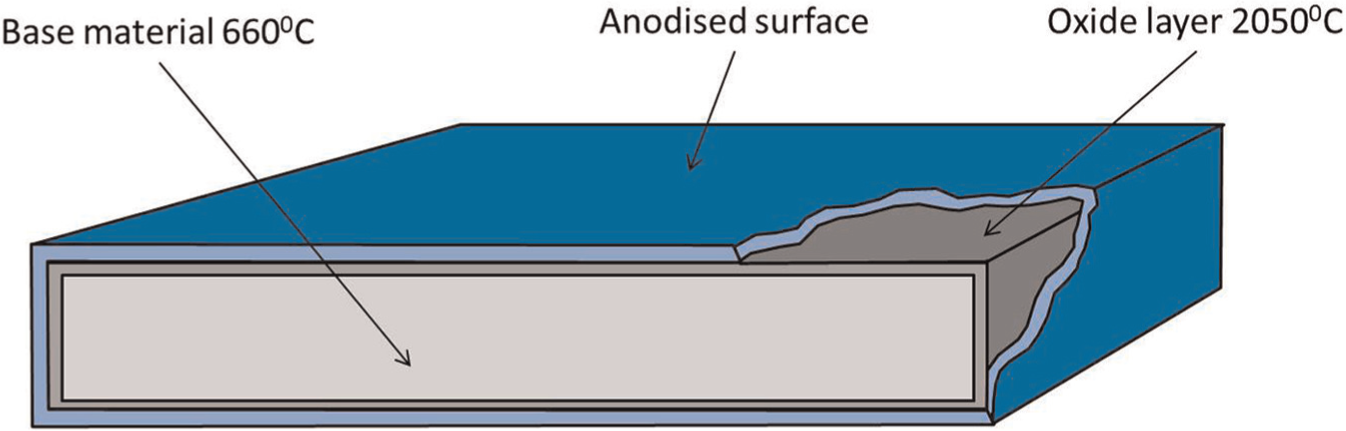
Schematic of aluminium showing its oxide layer and the anodised surface.
The aluminium oxide layer is, furthermore, an electrical insulator, and the layer may sometimes be thick enough to prevent arc initiation. In MIG processes, a thick oxide layer can produce erratic electrical commutation in the gun’s contact tube, resulting in poor welds.
It is thus evident that aluminium oxide has to be removed before welding because it compromises the quality of the weld. Generally, the oxide removal can be done by mechanical processes like brushing with a stainless steel brush, cutting with a saw or grinding with semi-flexible aluminium oxide grinding discs. 9 Some welding processes enhance additional oxide removal processes, for example, in ultrasound metal welding processes (UW), oxides and contaminates are removed by high-frequency motion, thus providing metal–metal contact and allowing for the work pieces to bond properly. 17 In hybrid laser MIG-welding of aluminium alloys, the MIG-welding process has a cleaning effect that removes the aluminium oxide layer. However, it is recommended that pre-weld cleaning of the weld surface should be carried out preferably by pickling or dry machining. 18 In gas-shielded arc welding, aluminium oxide removal from the weld pool can be done by cathode etching (which is controlled chemical surface corrosion done to reveal the details of the microstructure). 19 A direct current passes through the electrode connected to the positive pole of the power source. There is thus a flow of electrons from the work piece to the electrode and the ions flow in the opposite direction, bombarding the work piece surface. The aluminium oxide film is broken and dispersed by the ion bombardment, thereby allowing the flowing weld metal to fuse with the parent metal. It is advantageous to remove the aluminium oxide layer before welding because2,9
It significantly reduces the amount of hydrogen porosity in the weld.
It helps to improve the stability of the weld process especially in tungsten inert gas welding (TIG).
It allows for complete fusion of the weld. Cathode cleaning is important in TIG process as the oxide starts to form immediately after wire brushing.
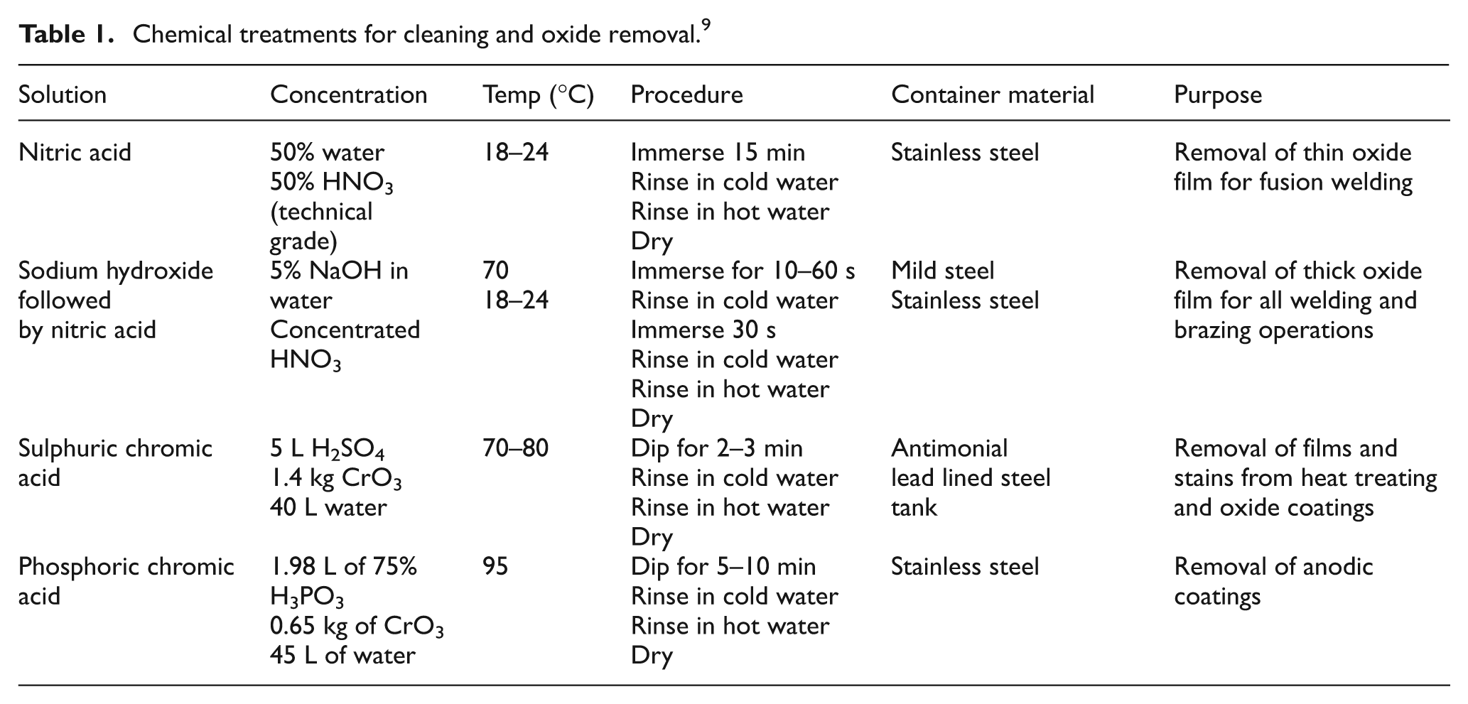
Aluminium oxide can also be removed by chemical etching or pickling. Table 1 presents chemical treatments for oxide layer removal. 9
Chemical treatments for cleaning and oxide removal. 9
One of the causes of the oxide layer is from anodisation, which is an electrochemical process by which a metal surface is converted into a decorative, durable, corrosion resistant anodic oxide finish.20,21 Anodisation utilises the unique ability of amorphous alumina to build up an even porous morphology 22 formed in alkaline and acidic electrolytes. During anodising, aluminium oxide is not applied like paint or plating. Rather, it is integrated fully with the underlying aluminium substrate. Therefore, it cannot peel or chip off. The anodic oxide structure is highly ordered and porous, thereby allowing for further processing like sealing and colouring. 20
The reasons for the utilisation of anodisation are to increase corrosion resistance and ensure the metal surface is fade proof for up to 50 years, 23 to improve decorative appearance, to increase abrasion resistance and paint adhesion, to improve adhesive bonding and lubricity, to provide unique decorative colours or electrical insulation, to permit subsequent plating, to detect surface flaws, to increase emissivity and to permit application of photographic and lithographic emulsions.14,20,24
Anodising of aluminium alloys is generally advantageous. However, it poses challenges for aluminium welding because the arc cleaning effect of the AC current cannot remove the double layer (the anodised layer and oxide layer as in Figure 1). Before welding, the anodised surface needs to be removed. 20
Shielding gas selection
Shielding gas protects the molten weld pool from the atmosphere, which is important because aluminium has a tendency to react with atmospheric air to form oxide and nitrides. The shielding gases commonly used in welding aluminium and its alloys are inert gases such as argon and helium.
Argon is used as a shielding gas for manual and automatic welding. Argon is cheaper than helium, and the use of argon produces a more stable arc and smoother welds. However, argon gives lower heat input and lower attainable welding speed, and therefore there is the possibility of a lack of fusion and porosity in thick sections. In addition, use of argon can result in a black sooty deposit on weld surfaces, although this can be wire brushed away. It has been observed that with helium shielding gas, the arc voltage is increased by 20%, resulting in a higher, hotter arc, deeper penetration and wider weld beads. This implies that the criticality of arc positioning (aids avoidance of missed edge and insufficient penetration defects) is lower with helium. There is a reduction in the level of porosity when helium shielding gas is used because the weld pool is hotter and there is slower cooling, which allows hydrogen to diffuse from the weld pool. Due to the higher heat produced, the use of helium allows that welding speeds up to three times higher than with argon. The high cost of helium and the inherent arc instability mean, however, that helium is used mainly in mechanised and automatic welding processes. 9
It is common practice to use a mixture of helium and argon as it provides a compromise on the advantages of each gas. Common combinations are 50% or 75% of helium in argon, which allow for better productivity by increasing the welding speed and provide a wider tolerance for acceptable welds. The purity of the shielding gas is of importance. At the torch, not at the cylinder regulator, a minimum purity requirement of 99.998% and low moisture levels of less than −50 °C (less than 39 parts per million (ppm) H2O) are expected. 9 Generally, the shielding gas should be selected with the following considerations.2,9,25,26
The gas must be able to generate plasma and a stable arc mechanism and characteristics.
It should provide smooth detachment of molten metal from the wire and fulfil the desired mode of metal transfer.
It should protect the welding head (in the arc’s immediate vicinity), molten pool and wire tip from oxidation.
It should help to attain good penetration and good weld bead profile.
It should not affect the welding speed of the process.
It should prevent undercutting tendencies.
It should limit the need for post-weld cleaning.
It should not be detrimental to the weld metal mechanical properties.
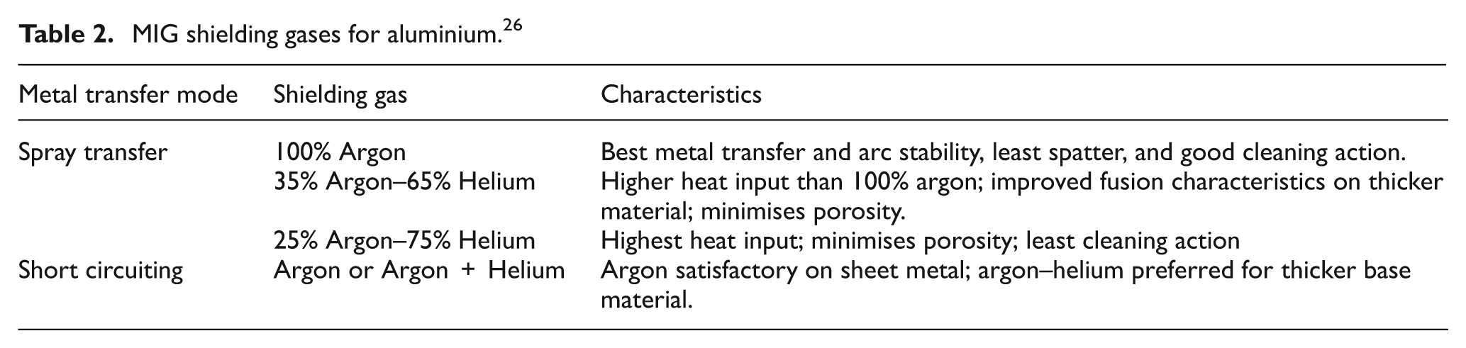
The recommended shielding gas for welding aluminium using pulsed MIG is argon (99.998%)25,27 at a flow rate of about 20 L/min. 27 A mixture of argon and helium can also be used and even helium alone. Helium increases the weld penetration and offers higher arc energy and thus increased deposition rate,27,28 and it should be used when the section is greater than 50 mm. 9 More details can be seen in Table 2, which presents MIG shielding gases for aluminium, and Table 3 presents the effects of shielding gases on aluminium welding. Studies have shown that welding of aluminium can be improved (arc stability) by oxygen doping of inert shielding gas. 29 In addition, the alternating shielding gases reduces weld porosity.30–32
MIG shielding gases for aluminium. 26
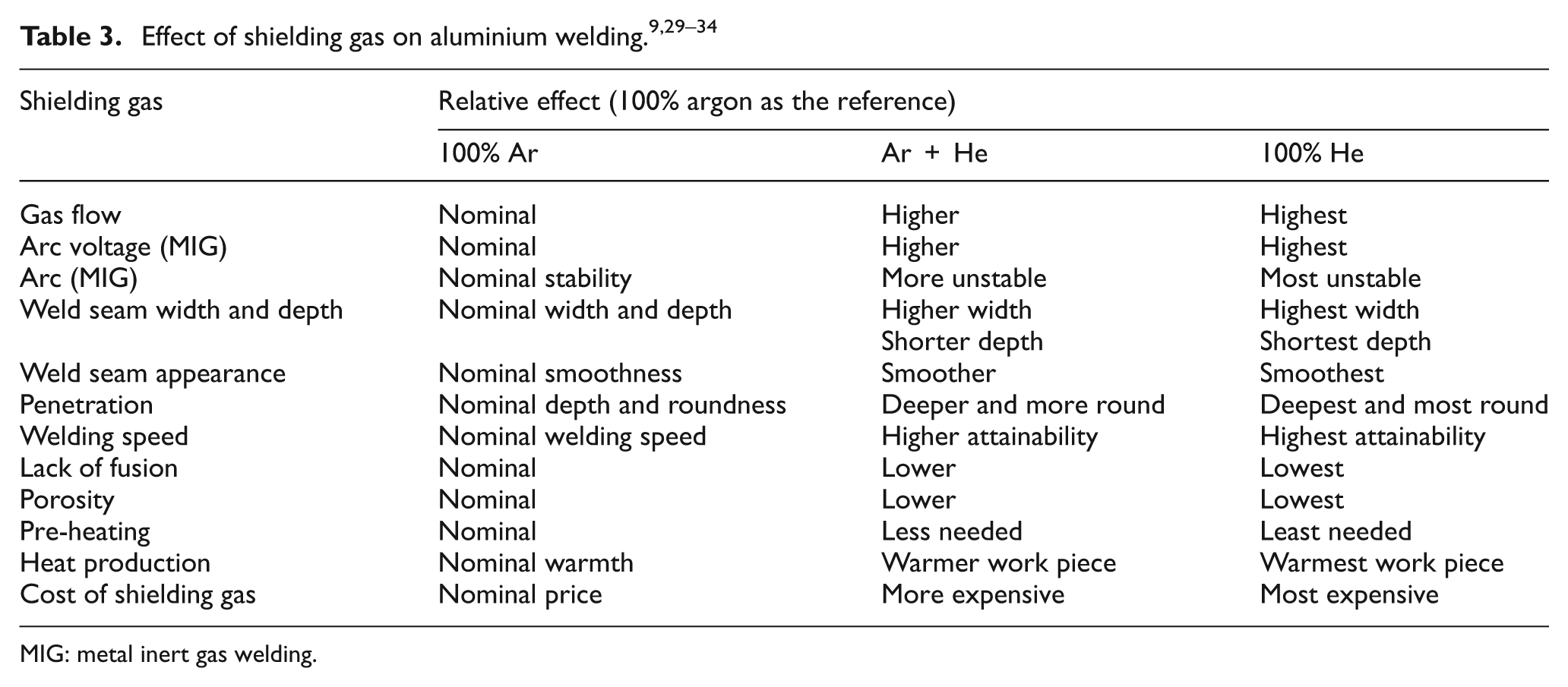
MIG: metal inert gas welding.
Joint types and process limitations
This article considers eight industrially accepted welding processes and six joint types. Joint design is important because it costs money to buy weld metal. The fillet throat, weld accessibility and the functionality of the welded work piece are taken into consideration in this design. The six joints considered are butt, T-joint, corner, cruciform, edge and lap joint (see Table 4), which are derived from the three basic welding joints (fillet, lap and butt joints). Joint designs are based on the strength requirements, the alloys to be joined, the thickness of the material, the joint type and location, weld accessibility and the welding process. Before choosing the joint design, it is important to note that welding in the flat or downward position is preferable in all arc-welding processes, as there is the easier possibility of depositing high-quality weld metal at a high deposition rate in a flat position. Additionally, the weld pool is larger, allowing for a slower cooling and solidification rate, which enhances the escape of trapped gases in the weld pool. The flat position reduces weld porosity, reduces weld cost, and gives the best weld metal quality compared with other positions. The static tensile strength of the weld is determined by the throat thickness, which must be designed to ensure that it can carry the workload for which the weld is designed. Conventional TIG and MIG processes produce weld metal on the surface of a plate during bead-on-plate welds to a depth of 3 mm for TIG and 6 mm for MIG. Therefore, to attain complete penetration for welds over 3 mm (MIG) and 6 mm (TIG), there is the need for bevelling on butt joints, for example. The bevel can be single or double sided. 9
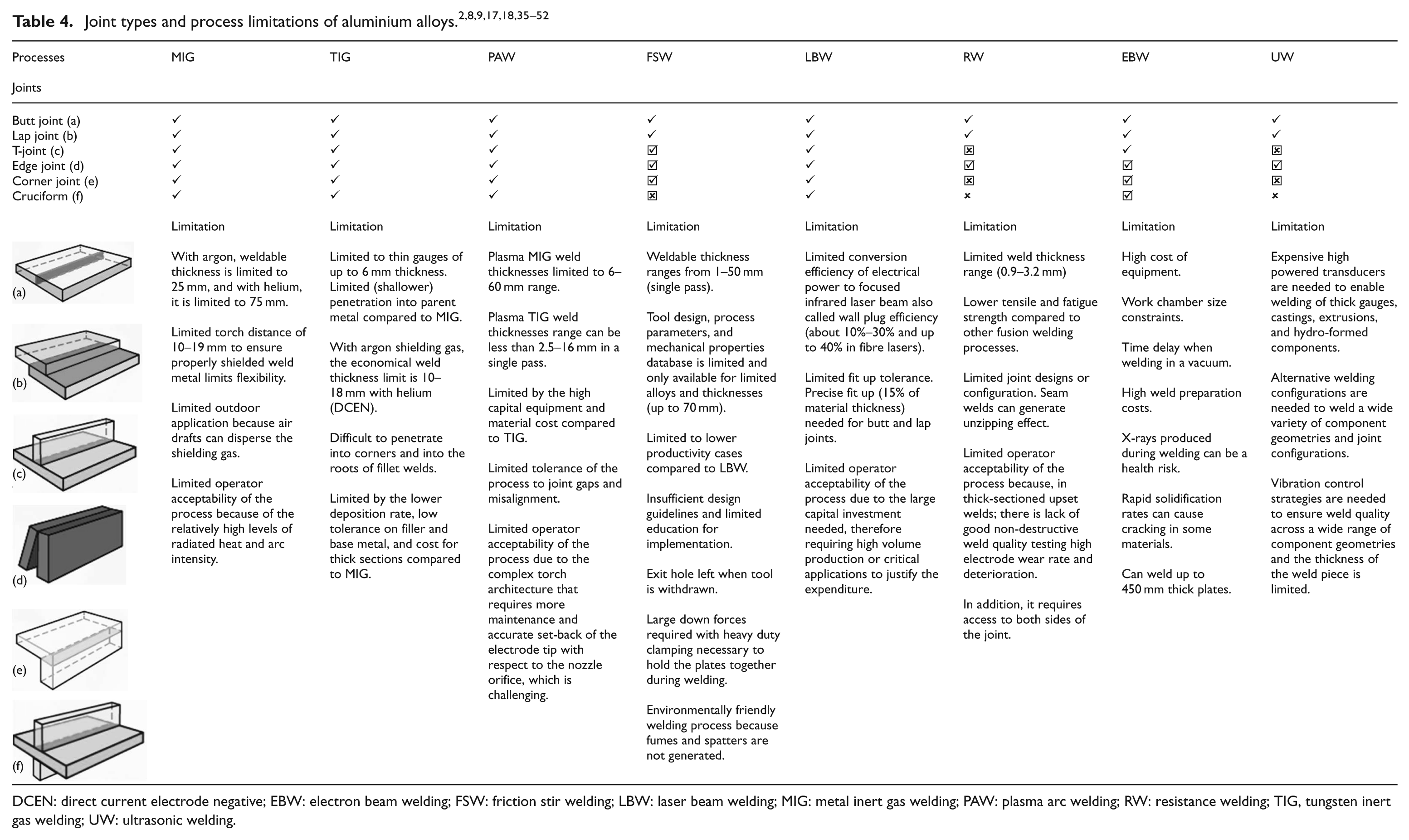
DCEN: direct current electrode negative; EBW: electron beam welding; FSW: friction stir welding; LBW: laser beam welding; MIG: metal inert gas welding; PAW: plasma arc welding; RW: resistance welding; TIG, tungsten inert gas welding; UW: ultrasonic welding.
As presented in Table 4, eight considered welding processes are correlated with their applicability on six different welding joints. Butt and lap joints are applicable to all the selected weld processes. Cruciform joints have the least applicability across the processes, which is due to limited fixturing possibility during welding. Table 4 provides additional information on the viability of six joint types on the eighth selected welding processes by presenting the process-specific limitations.
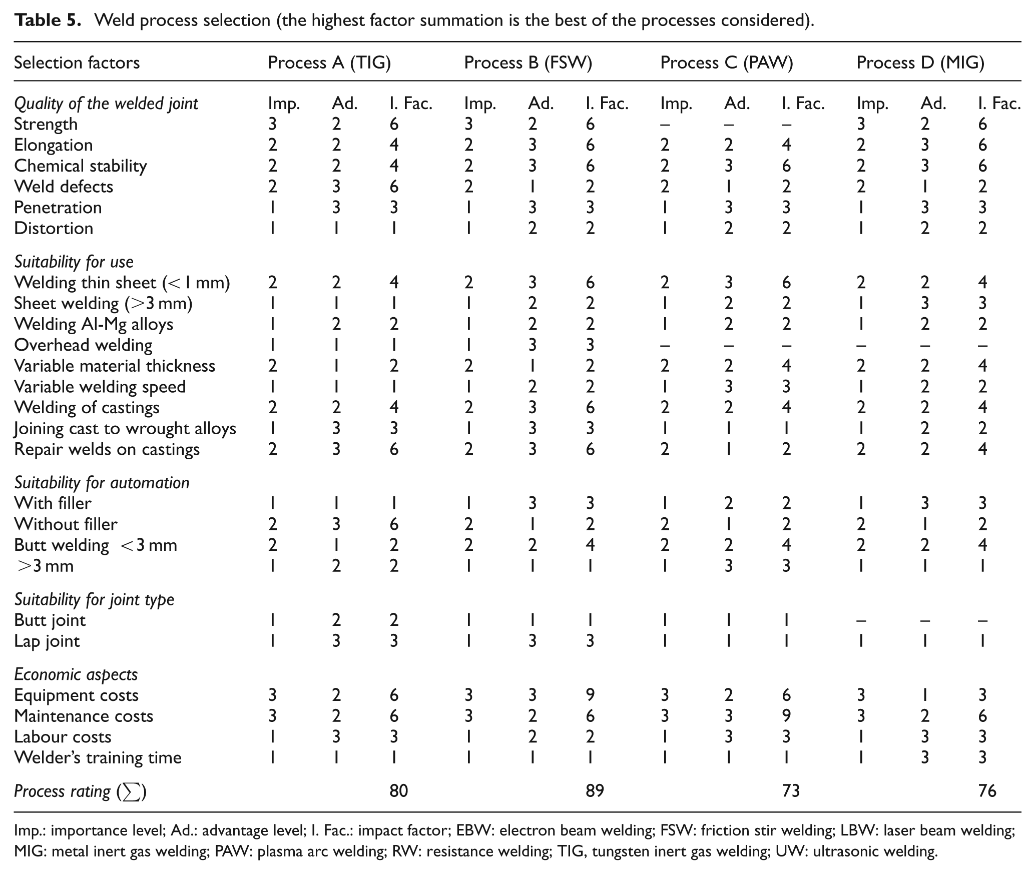
An application of this review article is to use the pre-stated information to influence the selection case-specific optimum welding process. It can be challenging to determine an appropriate welding process to be used for aluminium. However, the challenge can be simplified by considering various comparison selection factors as presented in Table 5. The solution to the challenge is case specific. An understanding of the selection factors considered provides better process selection and thus a better evaluation.
Weld process selection (the highest factor summation is the best of the processes considered).
Imp.: importance level; Ad.: advantage level; I. Fac.: impact factor; EBW: electron beam welding; FSW: friction stir welding; LBW: laser beam welding; MIG: metal inert gas welding; PAW: plasma arc welding; RW: resistance welding; TIG, tungsten inert gas welding; UW: ultrasonic welding.
It is important to point out that the scaling is subject to the designer’s discretion and not completely objective. The welding designer determines the importance level of the selected aluminium-welding project by answering a question like ‘how important is’ strength, elongation, chemical stability, etc., to the finished product. The designer defines the importance level on a scale of 1–3 (1= least, 2 = moderate and 3 = high). In a similar fashion, the advantageous level is determined by answering a question like ‘how advantageous is’ the selected welding process to the selected consideration. The importance level is multiplied by the advantage level and the result is called an impact factor. The impact factor is summed up for each selected welding process, and the welding process with the highest impact factor summation is selected as the optimal welding process.
Case study
A welding process for high-strength aluminium for aerospace is to be selected. The available welding processes are as presented in Table 5. A blank table is constructed and the considered welding processes are selected and filled into the table.
The selection factors under consideration are as presented in Table 5, which are categorised under quality of the weld joint, suitability for use, suitability of fillers, joint suitability and economics. Therefore, at this stage in the design, the processes row and the selection factor column are filled in the table.
As the designer, the importance level is determined and designed on a scale of 1–3, and using a scale of five is also applicable, but the calculation becomes more complex. Choosing a scale of 1–3 (1 = low, 2 = moderate and 3 = high), a number is assigned to the considered selection factor. Therefore, at this stage, the importance level of the selection factor under consideration is filled into the ‘Imp.’ column (Table 5). It is important to note that the number is the same across row (all processes) because the importance of a selection factor is independent of the process.
The advantage level is determined and designed by the designer on the same scaling used for importance level. If the scaling used in importance level is five, the scaling of five should be used. In this case, a scaling of 1–3 is used where 1 = low, 2 = moderate and 3 = high. At this stage, the entire advantageous level column on Table 5 is filled for all the considered selection factors into the ‘Ad.’ column.
The calculation for the impact factor and the process rating is carried out. The impact factor for each considered selection factor is derived by multiplying the importance level column of each process by advantageous level column of each process. The derived value is filled into the ‘I. Fac.’ (impact factor) column of Table 5. The process rating (welding process) is derived by the summation of all the impact values column of each process. Therefore, the process rating row is filled in Table 5.
The optimum weld process is the process with the highest process rating, which in this case study is process C friction stir welding (FSW).
Conclusion
This article examined the surface-related challenges, joint types and limitations of aluminium alloys with the focus on providing a guide on how to select an optimal welding process. Aluminium and its alloys have welding challenges, which include the presence of aluminium oxide on surfaces, welding of anodised aluminium and limited shielding gas options. The aluminium oxide surface is formed when aluminium is exposed to an atmosphere containing oxygen, and the aluminium oxide has to be cleaned away from the surface before welding because its causes weld defects like porosity.
The chemical affinity of aluminium for oxygen is utilised for anodising aluminium alloys and then painting to improve corrosion resistance. However, it can be detrimental when welding anodised aluminium as the anodised layer has to be cleaned before welding. The melting point of aluminium alloys is generally around 660 °C and the melting point of aluminium oxide is 2050 °C. It is therefore recommended that the aluminium oxide layer or the anodised layer be removed, mechanically or chemically, just before welding.
Aluminium alloys have high chemical affinity; therefore only inert gases can be used as shielding gases during welding. Argon and helium gases are used in aluminium welding to protect the weld pool. The presence of helium increases the arc heat input and therefore allows for deeper penetration compared with argon gas, but on the other hand, helium is more expensive than argon. A mixture of helium and argon is sometimes used to improve weldability of some aluminium alloys. A wider range of shielding gases would increase the manipulation possibility for aluminium alloy welding, but currently argon and helium are the only gases used.
The industrial welding processes considered in this work include MIG, TIG, plasma arc welding (PAW), FSW, LBW, resistance welding (RW), electron beam welding (EBW) and UW. The weldable thickness is a limitation in all the processes; the highest weldable thickness of up to 70 mm is achieved with EBW. FSW produces the best weld because the mechanical property deterioration is minimal, and the process is friendly as no fumes or spatters are produced during welding.
The joint configurations considered include the butt joint, lap joint, T-joint, edge joint, corner joints and cruciform joint. The butt joint and lap joint are applicable to all the considered welding processes. The possibility of using different joint orientations with the considered welding processes depends on the manipulation of the work piece (fixturing).
Although FSW produces the best weld for aluminium alloys, the optimal welding process is case specific. The designed table for weld process selection provides information on how to select the optimal process based on case-specific considerations for aluminium alloys.
Footnotes
Appendix 1
Declaration of conflicting interests
The authors declare that there are no conflicts of interest.
Funding
This research received no specific grant from any funding agency in the public, commercial or not-for-profit sectors.