
Abstract
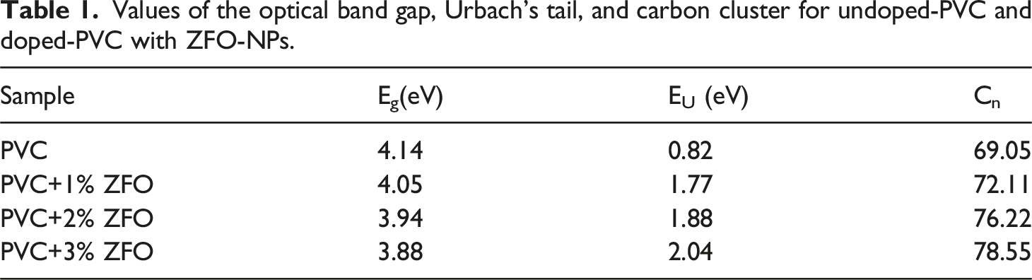
Herein, ZnFe2O4 nanoparticles (ZFO-NPs) were synthesized via the sol-gel method and doped into the PVC matrix by solution casting technique. This study aimed to examine the effects of PVC/ZnFe2O4 nanocomposites’ structural properties, dielectric constants, and linear/nonlinear optical characteristics at different concentrations of ZFO-NPs (0, 1, 2, and 3 wt.%). XRD pattern proved that the ZFO-NPs have a cubic crystal structure with a lattice constant of 8.5 Å and crystallite size of 39.97 nm. SEM image and EDX spectra were used to illustrate the surface morphology and elemental compositions of ZFO-NPs. The optical bandgap declined from 4.14 eV for the undoped-PVC to 4.05, 3.94, and 3.88 eV for PVC+1% ZFO, PVC+ 2% ZFO, and PVC+3% ZFO films, respectively. While Urbach’s energy (EU) rose from 0.82 eV to 1.77, 1.88, and 2.04 eV, respectively. It is found that the values of the free carrier increase after the introduction of the nano-ZFO from 2.61 × 1014 cm−3 for the undoped-PVC polymer to 4.15 × 10¹⁹, 5.78 × 10¹⁹, and 6.21 × 10¹⁹ for PVC+1% ZFO, PVC+ 2% ZFO, and PVC+3% ZFO, respectively. Furthermore, the optical mobility increases from 8.73 × 10⁻⁴ c.s.kg−1 to 2.26 c.s.kg−1. In contrast, the optical resistivity of the pristine PVC is 0.275, which decreases to 3.1 × 10⁻⁹, 4.78 × 10⁻¹⁰, and 2.72 × 10⁻⁹ c−2.s−1kg−1 for the PVC+1% ZFO, PVC+ 2% ZFO, and PVC+3% ZFO, respectively. Moreover, the effect of ZFO-NPs on the nonlinear properties of PVC/ZnFe2O4 nanocomposites was addressed. Finally, the linear and nonlinear optical characteristics of doped-PVC with ZnFe2O4 NPs make them suitable for electronic devices.
Introduction
The field of nanocomposite materials has garnered significant attention in recent years for research purposes and industrial uses.1,2 This is because the general efficiency of polymeric materials can be enhanced by relatively little nano-additive.3–9 The nanomaterials’ intense interfacial interaction, enormous specific area, confined quantum impacts, and tiny size are the reasons associated with this. 10 Various polymer nanocomposites, including PVDF/SrTiO3/CNT, 11 PVC/La2O3, 12 and PVDF/CaFe2O4, 13 were employed in the field of optoelectronics and solar cells.
One of the most extensively produced and ingested polymers worldwide is poly(vinyl chloride) (PVC).14–16 It is a thermoplastic material extensively used due to its outstanding chemical resistance and high flame retardancy. 17 Electromagnetic interference shielding and attenuation were performed with PVC/graphite nanocomposites. 18 In recent years, there has been a significant increase in the interest in polymers’ electrical and optical properties due to their potential applications in optical devices that exhibit exceptional reflection, antireflection, interference, and polarization properties. Charge carriers provide the conductivity of materials formed from holes and electron pairs when photons of light enter the coating, transfer across the conjugate bonds electrons of polymers, and then transport to the lower, unoccupied orbital. Therefore, the polymers may be photoconductive materials. The optoelectrical properties of PVC will be enhanced by adding suitable dopant materials and additives, as it has a low thermal conductivity and high resistance.19,20 The optical band gap of PVC/Cu/Cu2O nanocomposites declined as the ratio of Cu/Cu2O in PVC enhanced while the Eu energy improved. 21 Compared to pure PVC, PVC/ZnO nanocomposites exhibited an elevated glass transition temperature (Tg), specific heat, and thermal resistance. 22
Zinc ferrites ZnFe2O4 nanoparticles (ZFO-NPs) possess ferromagnetic characteristics and show a spinel crystal structure at ambient temperature.23,24 Furthermore, ZFO-NPs possess magnetic features and a high dielectric constant, facilitating the regulation of polymer composite qualities. 25 The material’s optical, magnetic, and electrical properties are enhanced when ZFO-NPs are incorporated into a nonmagnetic polymer. Polymer ferrite nanocomposites demonstrate significant advantages in both organic and inorganic materials. Spinel ferrites, particularly ZFO-NPs, are a substantial class of nanomaterials in technology due to their magnetic, optical, photocatalytic, magnetic, and catalytic properties. Therefore, the potential for their use in producing magnetic nanohybrids and polymer nanocomposites is significant in a wide range of modern industry and technological fields.25–27 ZFO-NPs were incorporated into the polyindole/poly(vinyl alcohol) composite to enhance its thermal, mechanical, and dielectric characteristics. 28 Another investigation demonstrated the influence of ZFO-NPs on the dielectric and ferroelectric properties of PVDF/ZFO nanocomposites. 29
Previous research on nanocomposites developed from PVC has concentrated chiefly on developing better mechanical, thermal, or magnetic characteristics, with less attention given to investigating the linear/nonlinear optical characteristics. Despite considering the nonlinear optical and optoelectronics capabilities, the investigations frequently employ other NPs lacking the multifunctionality offered by ZFO-NPs.
Despite a thorough literature search, no studies have examined the effect of ZFO-NPs on the PVC nanocomposites’ linear and nonlinear optical properties. Consequently, the primary objectives of this investigation are the structure, linear, and nonlinear optical characteristics of undoped- and doped-PVC with ZFO-NPs and their preparation using the solution casting method. ZFO NPs were incorporated into a PVC matrix with various contents (0, 1, 2, and 3 wt.%). XRD, SEM, EDX, and FTIR measurements were implemented to investigate the structural characteristics of PVC/ZFO nanocomposites. UV-Vis spectroscopy will be employed to acquire both linear and nonlinear optical data.
Experimental
The reagents employed in this study are of analytical grade and were not purified. Double-distilled water was implemented in each investigation. Citric acid monohydrate, zinc nitrate hexahydrate (Zn(NO3)2·6H2O), and iron (III) nitrate nonahydrate (Fe(NO3)3·9H2O). The polyvinyl chloride (PVC) hails from Fluka, Romania. The solvent used was pure tetrahydrofuran (THF) from New Delhi, INDIA.
The sol-gel method was employed to synthesize ZFO-NPs, with Fe(NO3)3·9H2O and zinc Zn(NO3)2·6H2O serving as sources for Fe and Zn, respectively. Initially, 60 mL of distilled water was used to dissolve a stoichiometric ratio of Fe: Zn salts (2:1). The two solutions were combined and agitated at 80°C for 45 min, during which a 50 mL of 3 M citric acid monohydrate solution was introduced as an efficient fuel. The gel formation is facilitated by heating the resultant solution to 120°C for 2 hours. The ZFO-NPs were produced by drying and grinding the resulting powder. Finally, the ZFO-NPs are sintered at 600°C for 2 h. 30
A homogeneous fine particle is produced by slowly grinding ZFO-NPs. 1 g of PVC powder was stirred in 20 mL of THF in a glass beaker at ambient temperature for an hour to create a solution. Subsequently, the PVC was subjected to stirring for an additional 30 min after the addition of varying proportions of ZFO-NPs (0, 1, 2, and 3 wt.%). Finally, the PVC/ZFO films were produced by casting the mixture into a glass dish and allowing it to dry.
The films of pure PVC and PVC filled with ZFO NPs were characterized. The X-ray diffraction (XRD) Shimadzu 6000 was employed to conduct the crystal structure. The functional groups of PVC/ZFO nanocomposite films were recorded using a Nicolet iS10, USA, FTIR absorption spectrometer. Scanning electron microscopy (SEM) and energy dispersive X-ray spectroscopy (EDX) were employed to estimate the surface morphology and elemental composition, respectively, using the Inspect S system from FEI (Holland). UV-vis-NIR spectrophotometer (Jasco, V-570) was used for optical characterization.
Results and discussion
Structural study
Figure 1 displays the X-ray diffraction XRD pattern of the ZFO-NPs. The ZFO-NPs pattern revealed peaks at 29.65, 34.97, 42.55, 52.85, 56.35, and 61.89°, which align with the data of a cubic crystal structure of ZFO-NPs found in JCPDS Card No. 82–1049. Furthermore, the lattice constant of ZFO-NPs was precisely measured to be 8.50 Å.
25
The ZFO-NPs crystallite size (D) has been estimated using the Scherrer equation
31
: XRD pattern of ZFO-NPs.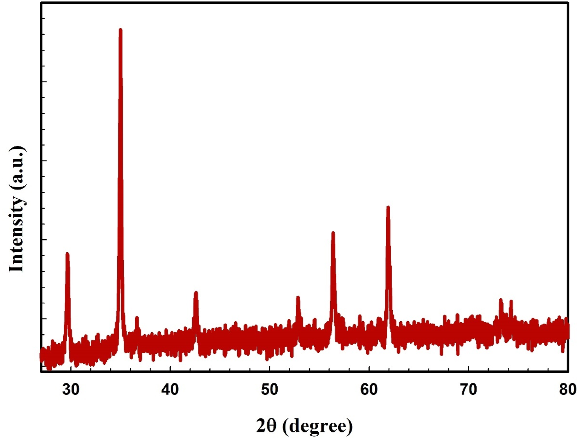
The symbol λ denotes the wavelength of radiation, β indicates the entire width at half maximum of the diffraction peak, and θ corresponds to the Bragg angle. The D value of the ZFO-NPs has been established at 39.97 nm.
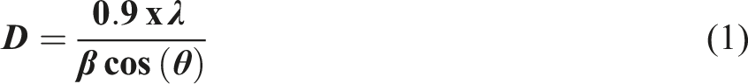
The scanning electron microscope (SEM) images of the ZFO-NPs are shown in Figure 2(a), showing that the ZFO-NPs have a consistent and uniform shape. The elemental composition and EDX spectrum of ZFO-NPs powder are shown in Figure 2(b). The chemical makeup of ZFO-NPs consists of zinc (Zn), iron (Fe), and oxygen (O). The figure validated that the ZFO-NPs were pure and free from extraneous materials. (a) SEM image and (b) EDX spectra of the ZFO-NPs.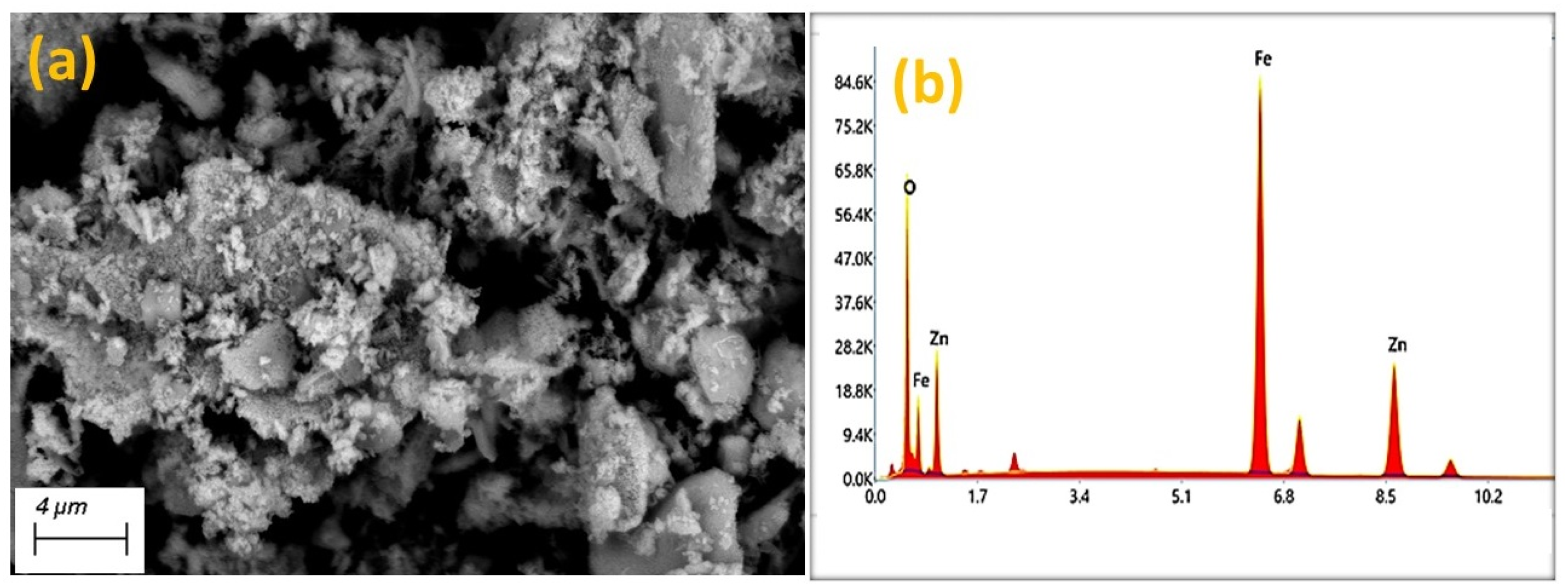
Figure 3(a) shows the XRD patterns of undoped-PVC and nanocomposite films of doped-PVC with different concentrations (0, 1, 2, and 3 wt.%) of ZFO NPs. The noted pattern of undoped-PVC validates the amorphous nature of the PVC.
32
Moreover, when the concentration of ZFO-NPs in the PVC matrix rises, there is a gradual rise in the intensity of the ZFO-NPs peaks. This figure further confirmed the successful preparation of PVC/ZFO nanocomposites. (a) XRD patterns and (b) FTIR spectra of undoped-PVC and nanocomposite films of doped-PVC with different concentrations (0, 1, 2, and 3 wt.%) of ZFO NPs.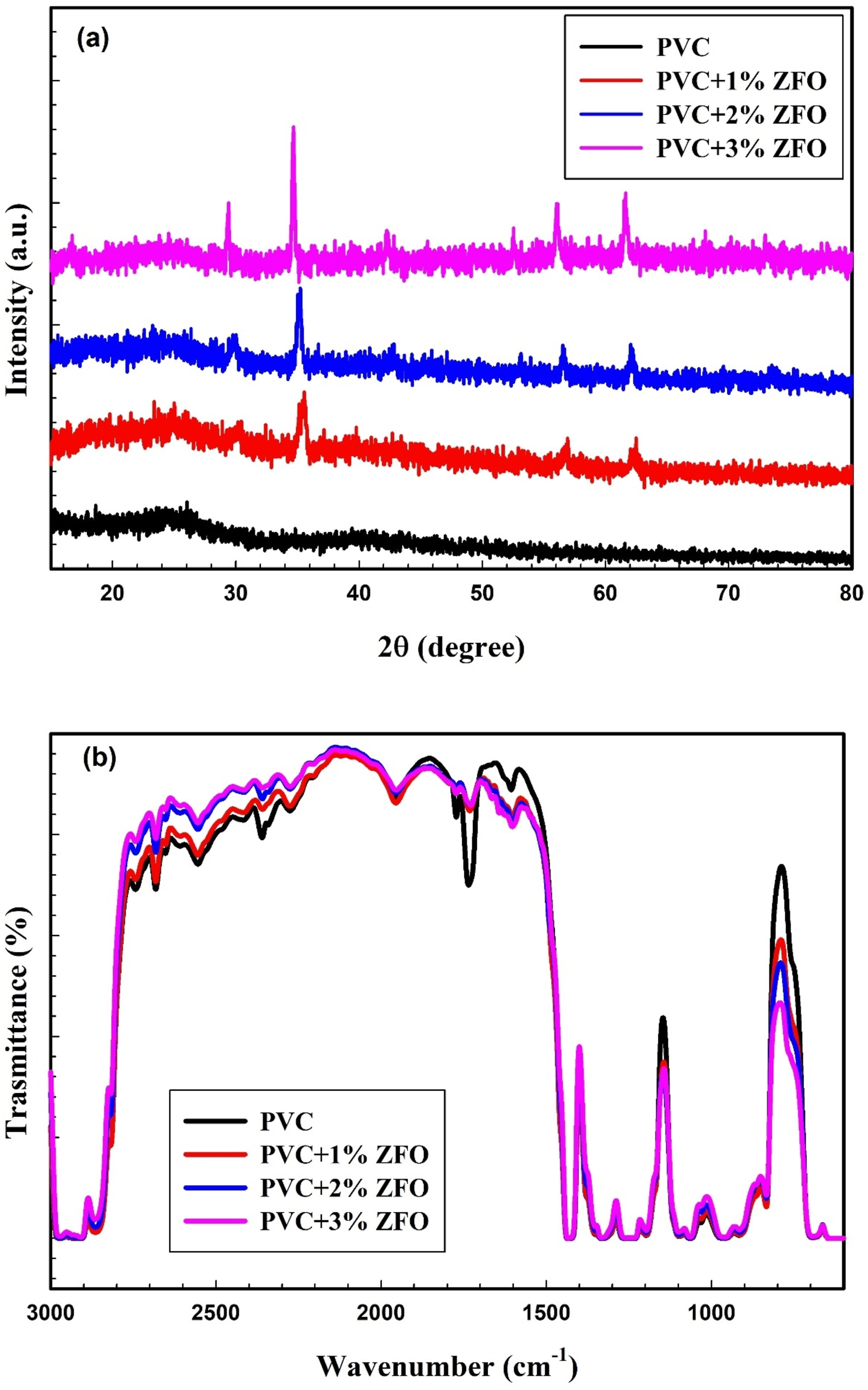
Physical and chemical interactions between ZFO and PVC matrix are among the numerous processes that may occur. The surface of ZFO-NPs is linked to the PVC polymer chains by weak, non-covalent interactions through Van der Waals forces. The possibility of hydrogen bonding between the oxygen atoms from the surface of ZFO-NPs and the hydrogen atoms in the PVC chains.33–37
The FTIR spectra of PVC/ZFO films (0, 1, 2, and 3 wt.%) are illustrated in Figure 3(b). The asymmetric stretching vibration of the C–H band can be observed at 2910 cm−1. The stretching vibration of the C–H band is discernible at 1425 cm−1. The bands at 1330 cm−1 and 1255 cm−1 have been attributed to CH2 deformation and the rocking mode of the C–H bond near Cl, respectively. The C–C stretching vibration was noticed at 1090 cm−1. The wagging mode of trans-CH can be observed at 955 cm−1. The stretching vibration of C–Cl is 833 cm−1.21,25,38,39 The band position and intensity of the bands are slightly altered as the concentration of ZFO NPs in PVC/ZFO nanocomposites increases. XRD patterns and FTIR spectra confirmed the successful preparation of PVC/ZFO nanocomposites.
Optical properties
Figure 4 reveals the variations in the optical absorbance (A) of the pristine PVC film and three films of the ZFO-doped PVC. For the pristine PVC film, it can be seen that this film presented a peak at ∼ 280 nm, which is due to the transfer of the electron from π→π* and n → π* transitions caused by (C = C) unsaturated bonds.21,40 Moreover, a sharp decrease in the spectrum appeared in the 200–230 nm region assigned to the band gap of the PVC film. It can be seen that in PVC doped with different contents of the ZFO NPs, the peaks at 280 nm shifted toward a lower photon energy (redshift), which reveals the reduction in band gap after the addition of ZFO and the complexation between PVC polymer and ZFO NPs.
41
The red shift was noticed after the insertion of the ZFO is useful for various applications, including photonics devices (lasers), optical filters, and photodetectors. Sensors also use this tendency to produce detectors susceptible to particular wavelengths. It is also interesting to observe enhancing the optical absorbance across the entire wavelength range when ZFO-NPs are introduced into PVC, in which the absorbance gradually increases with the concentration of ZFO-NPs. The increase in absorbance upon addition the ZFO may be owing to improvement the host matrix’s absorbance of the PVC polymer and its ability to block the light from being transformed within it.
42
The significant absorbance in the ultraviolet (UV) area of the doped-PVC with ZFO-NPs makes them well-suited for applications requiring ultraviolet shielding.
43
The PVC/ZFO nanocomposite films’ absorbance.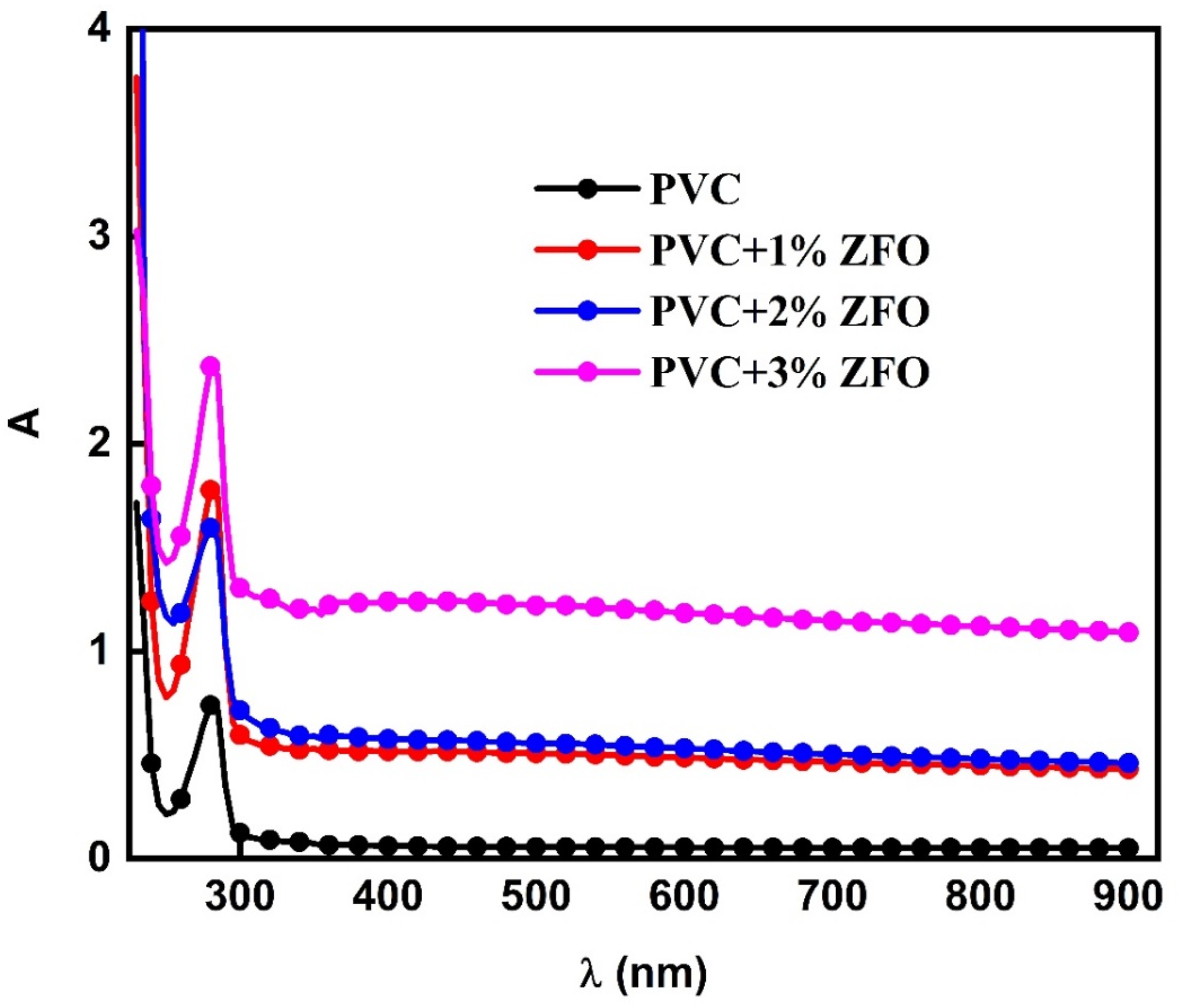
For further study, the spectra of optical transmittance (T) and optical reflectance (R) versus the wavelength (λ nm) for the undoped- PVC and the doped films with different ratios of the ZFO-NPs are shown in Figure 5. It can be seen that as PVC was loaded with different contents of the nanofiller, its transmittance decreased across the entire wavelength range. The reduction in optical transmission may be owing to the increased in photon scattering by ZFO-NPs within the PVC or the decrease in transparency of the PVC/ZFO nanocomposite films. The spectra of optical transmittance (T) and optical reflectance (R) versus the wavelength (λ) for the undoped-PVC and the doped PVC-films with different ratios of the ZFO-NPs.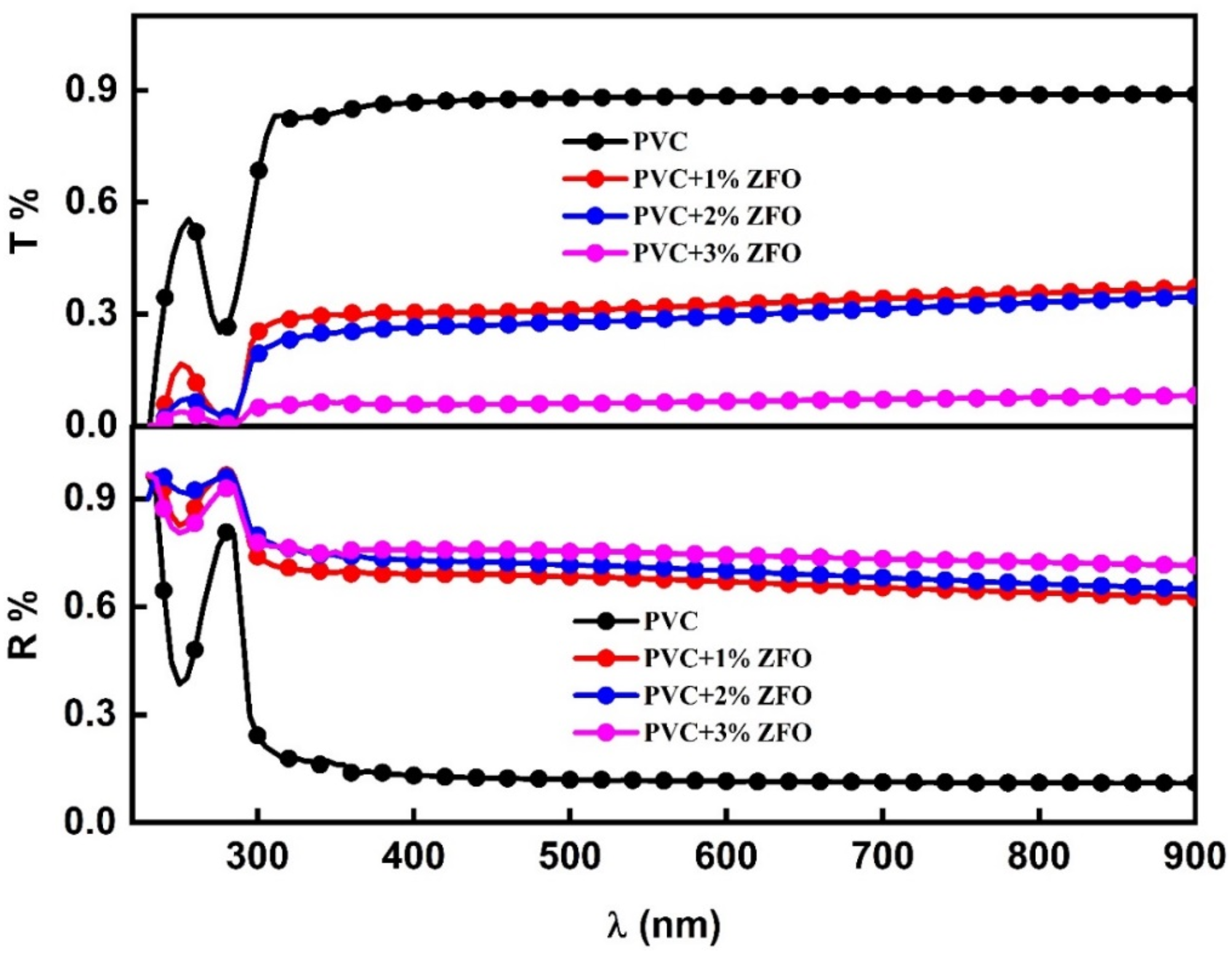
For the reflectance spectra, a significant increase was observed when the ZFO-NPs were introduced, in which this increase reached 3.6 times the pristine PVC value. The enhancement in optical reflectance of the PVC/ZFO nanocomposite is ascribed to the augmentation in light scattering induced by incorporating ZFO-NPs. 44 Besides, the interaction between PVC and the ZFO-NPs contents also play a role on the molecular level, which result in a modification in the electronic structure, therefore induces on its optical properties.
The band gap is a substantial parameter for photovoltaic and optoelectronic materials owing to using it in defining the maximum theoretical efficiency which can be achieved. From the optical absorbance data (A), the optical bandgap (Eg) of the undoped-PVC and the doped-PVC films with different concentrations of the ZFO NPs was extracted using the Tauc’s equation as follows
45
:

where α is the absorption coefficient ( Values of the optical band gap, Urbach’s tail, and carbon cluster for undoped-PVC and doped-PVC with ZFO-NPs.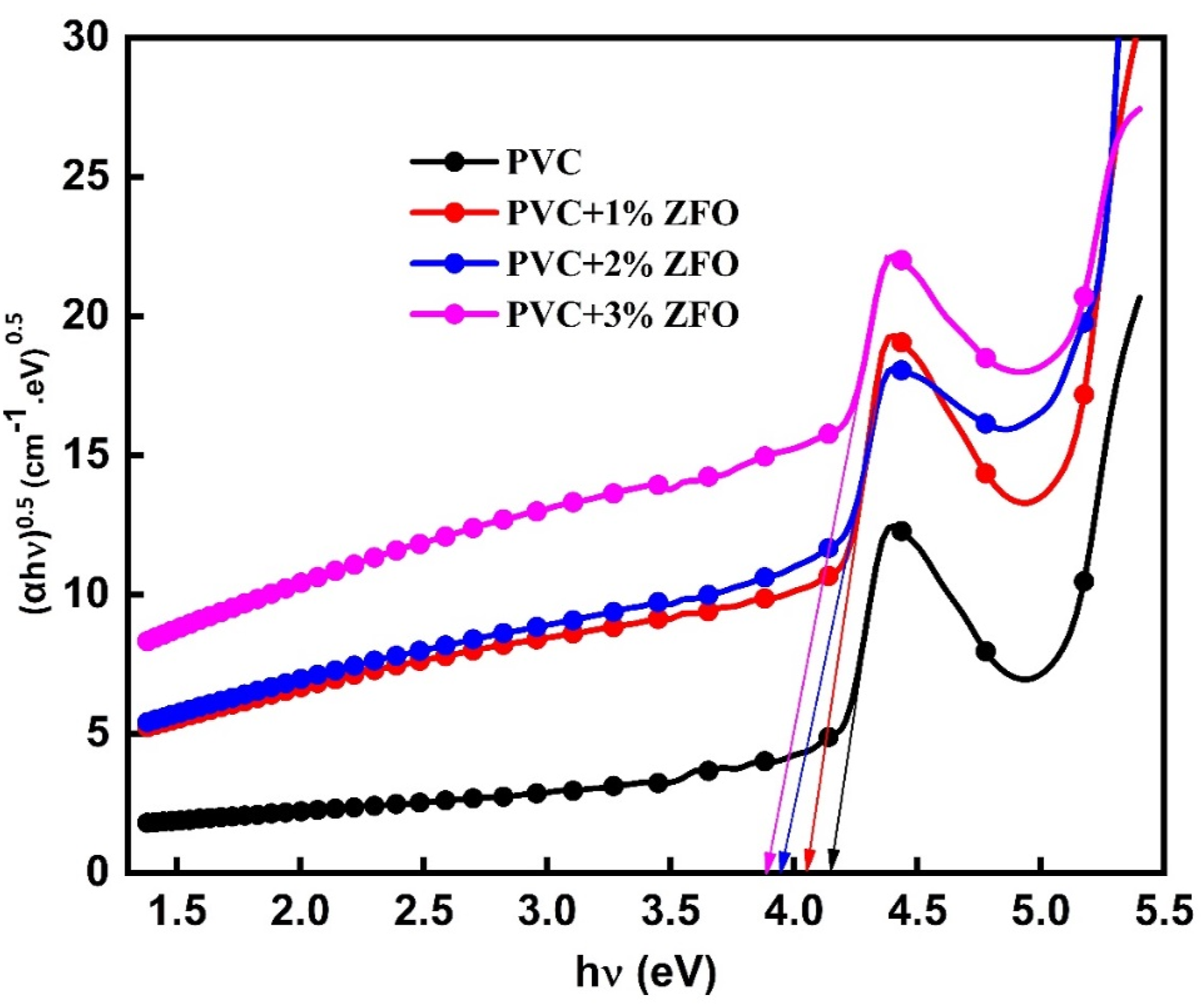
From the optical band gap, the number of carbon atoms per cluster (Cn) was deduced using the following expression
48
:
The values of carbon cluster were presented in Table 1. Additionally, the carbon cluster value of the PVC polymer increases after insertion the ZFO-NPs. In which, it increases from 69.05 to 72.11, 76.22, and 78.55 for PVC+1% ZFO, PVC+2% ZFO, and PVC+3% ZFO films, respectively. This increase may be owing to break of the C–H bonds and release hydrogen. 49
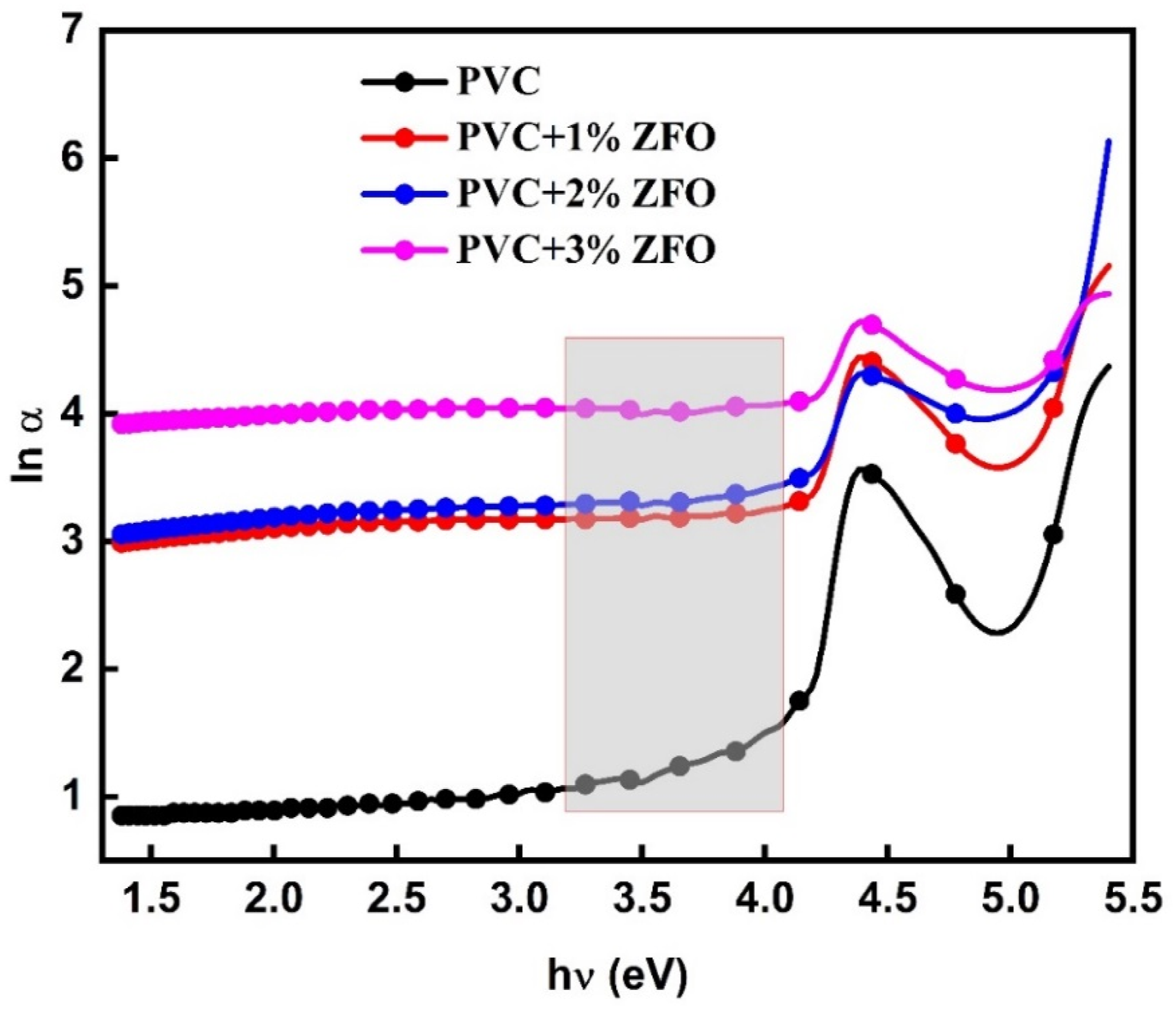
Additionally, values of Urbach’s tail are used to record the optical transition between the localized and band states. The following equation may be used to get the absorption coefficient (α) in this region
50
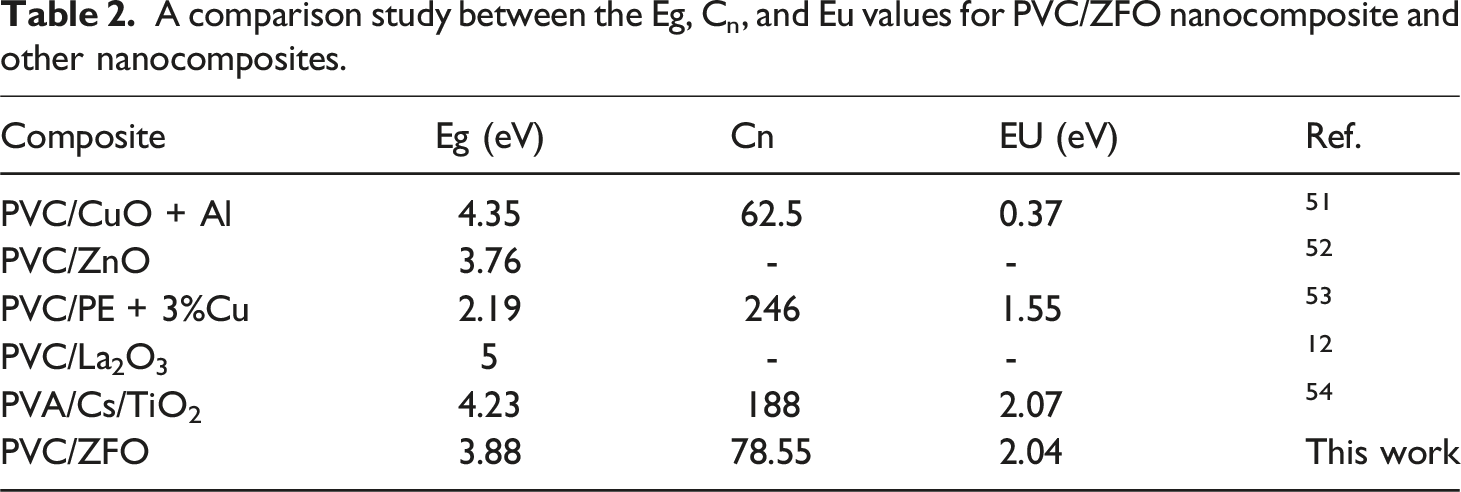
: ln (α) versus A comparison study between the Eg, Cn, and Eu values for PVC/ZFO nanocomposite and other nanocomposites.
The extinction coefficient (k) can be used for measuring the light lost due to the absorption and scattering per unit the distance of a penetration medium. From the data of the absorption coefficient, the indexed of extinction coefficient can be calculated according to the following expression
55
:
Figure 8(a) records the extinction index as a function of wavelength in the range of 200-900 nm of the undoped-PVC and ZFO-doped PVC. It is notice that k values of the PVC increase after introducing the ZFO. This trend may be attributed to that addition the nanofiller produces new electronic state in the nanocomposite films, which can enhance its optical properties including the optical absorbance of light, and then the extinction index. Further, the nanoparticles of ZFO-NPs hold amazing optical properties, such as strong light scattering and a high dielectric constant.
47
Examining the refractive index (n) is crucial for understanding the characteristics of undoped- and doped-PVC since it is directly linked to the ion’s electronic polarizability and the local field throughout the PVC films. The refractive index of the undoped-PVC and ZFO NPs doped-PVC films may be determined using the equation below
56
: Variations in spectra of (a) k and (n) versus 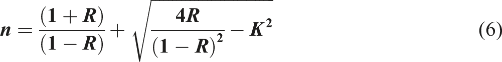
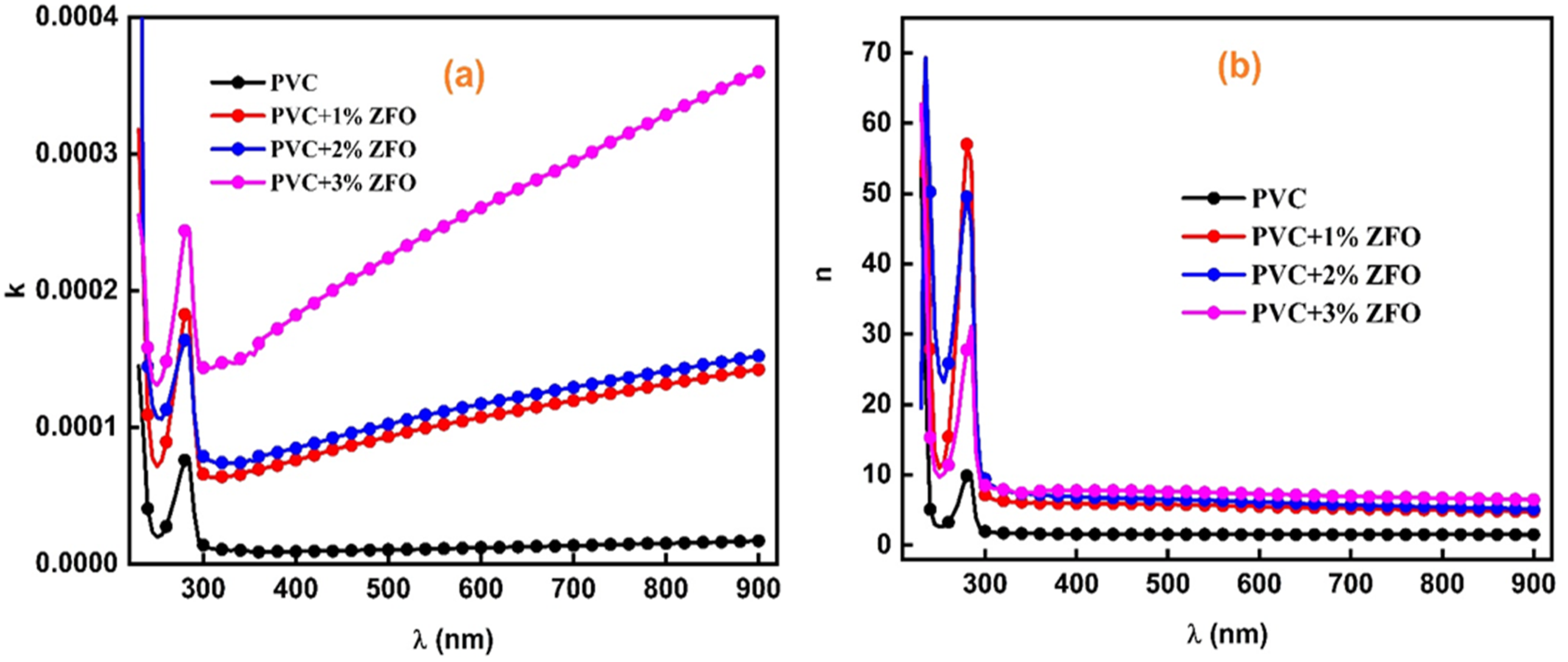
Figure 8(b) depicts the change in the refractive index as a function of wavelength (λ) of the undoped-PVC and ZFO NPs doped-PVC film. The graph illustrates a progressive rise in the refractive index after incorporation different concentrations of the ZFO-NPs. In which this increment reached 5.2 times the pristine PVC value. The more potent chemical and intermolecular interactions between the ZFO-NPs and the neighboring PVC chain segments are responsible for this increase, which result in an enhancement in the densities of doped-PVC films, leading to a higher refractive index. 57 These results affirmed that the doped films by ZFO-NPs can be employed in some application, e.g., optical adhesives, filters, ophthalmic lenses, highly reflective, and antireflection coatings due to its higher refractive index.
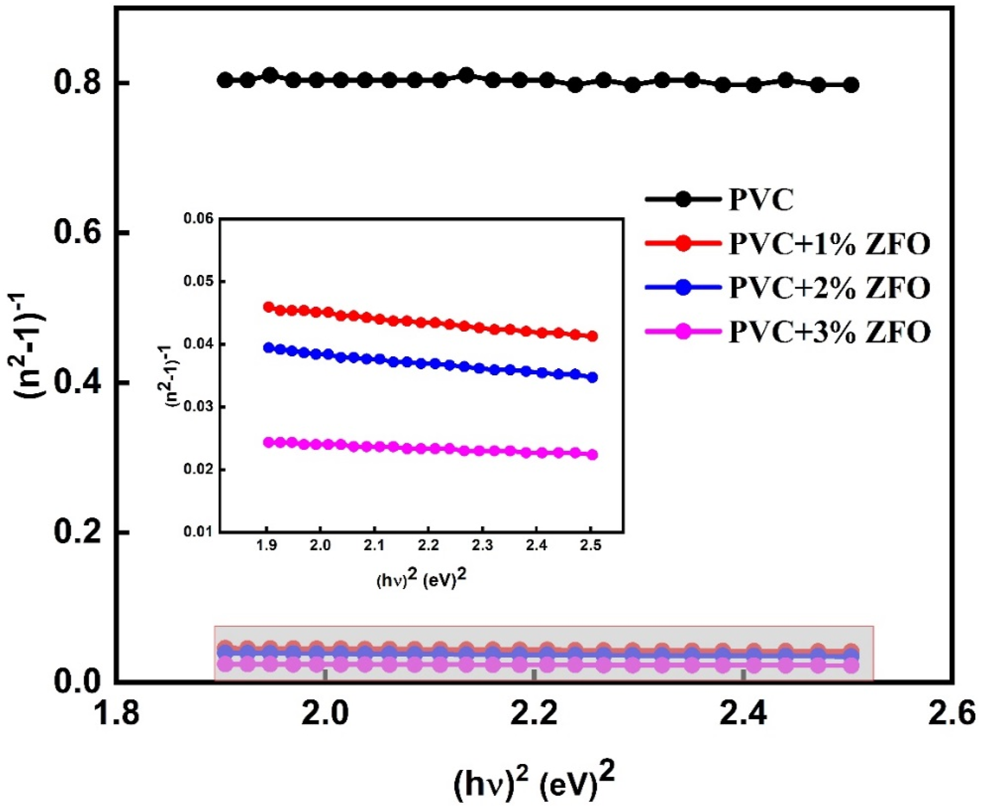
The undoped-PVC and doped-PVC with ZFO-NPs under study exhibit a normal dispersion in the refractive index inside the transparent region (λ > 600). Therefore, the dispersion of the for undoped-PVC and doped-PVC with ZFO-NPs is determined through using the Wemple and DiDomenico relation
58
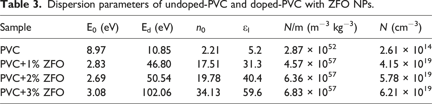
: (n2 − 1)−1 vs ( Dispersion parameters of undoped-PVC and doped-PVC with ZFO NPs.
Additionally, at zero frequency (hv→0), the static refractive index values (n
o
) of samples are deduced using the following relationship
59
:
The computed n 0 values of the undoped-PVC and doped-PVC with ZFO NPs were seen in Table 3. It is evident that values of n0 significantly increase with increasing the ratio of ZFO-NPs from 1 to 3% wt., in which the increase in n 0 from 2.21 to 34.13, widening the use of the prepared PVC/ZFO nanocomposite.
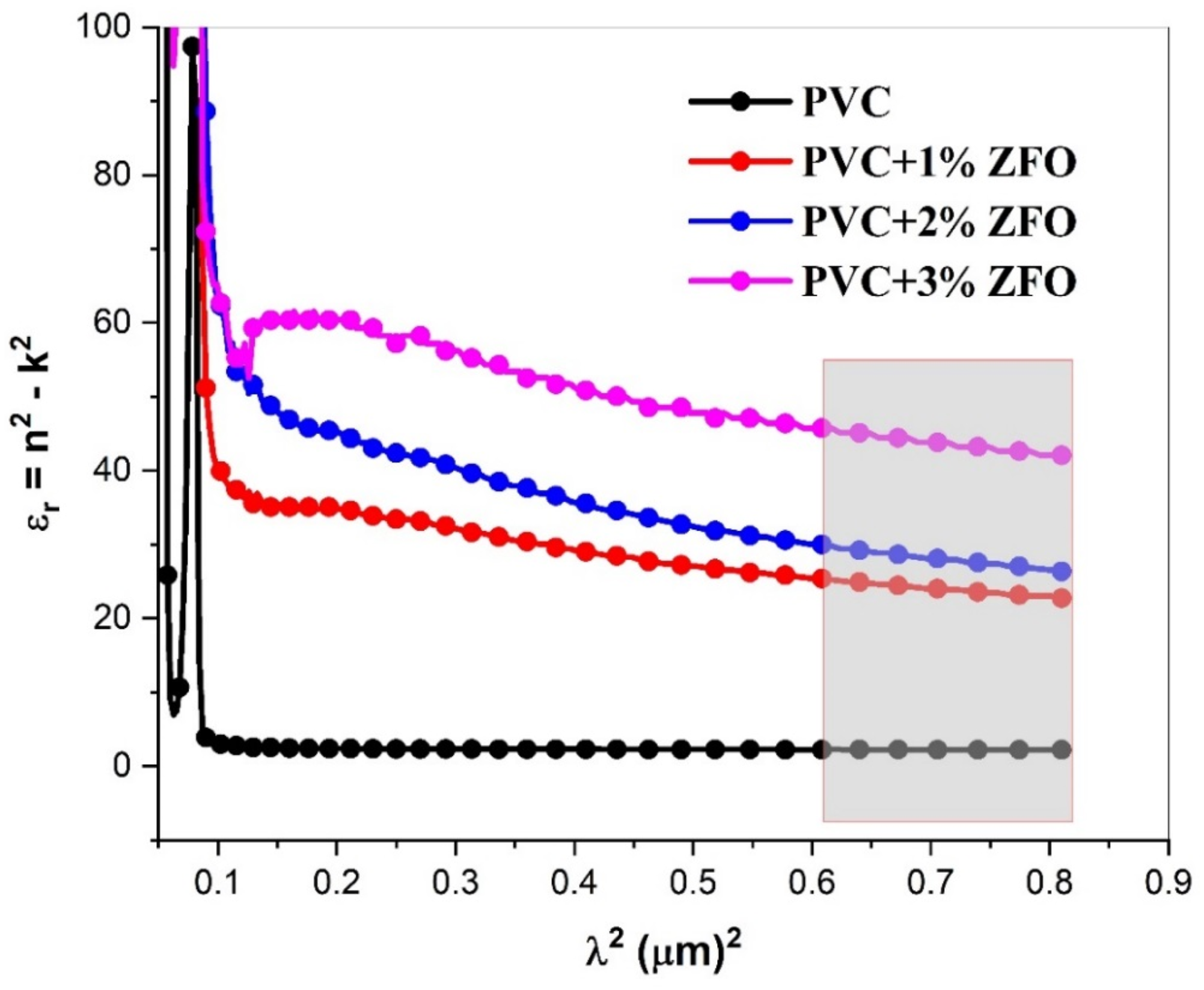
In the Spitzer–Fan model, the real part of dielectric constant (εr) can be given by the following expression
60
: The variation in εr as a function of λ2 of the undoped- and doped-PVC with ZFO NPs.
The oscillation frequency (ω
P
) of the undoped and doped films is assigned to the real part of dielectric constant (ε
r
) according to the following equation
61
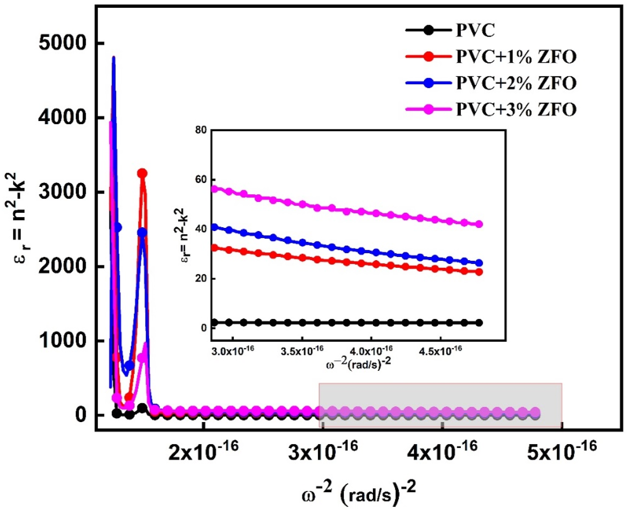
: The relation between ε
r
and 1/ Optoelectrical parameters for the undoped- and doped-PVC with ZFO-NPs.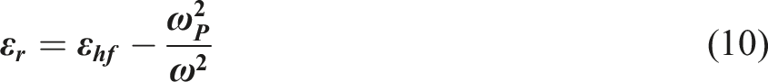
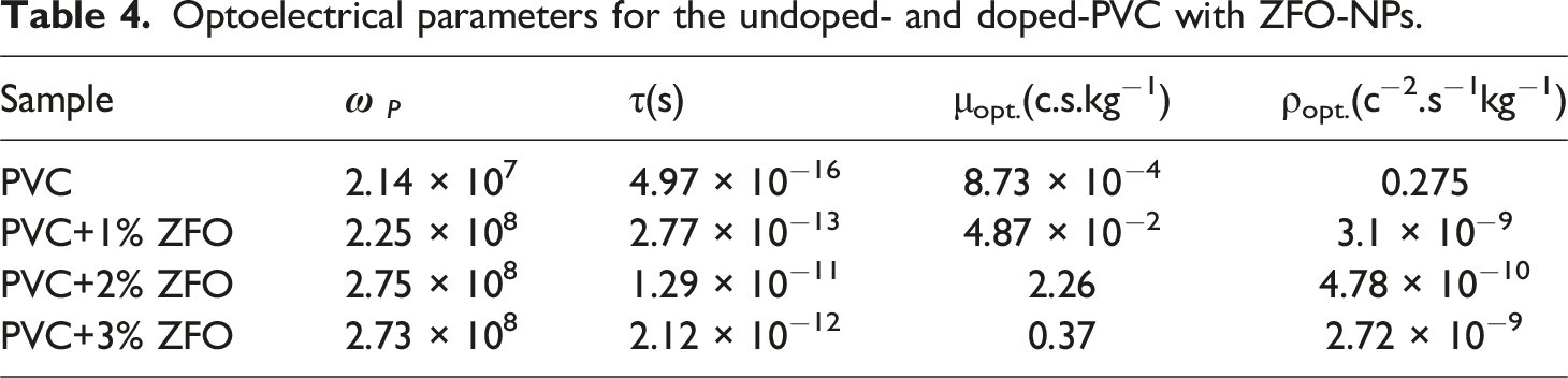
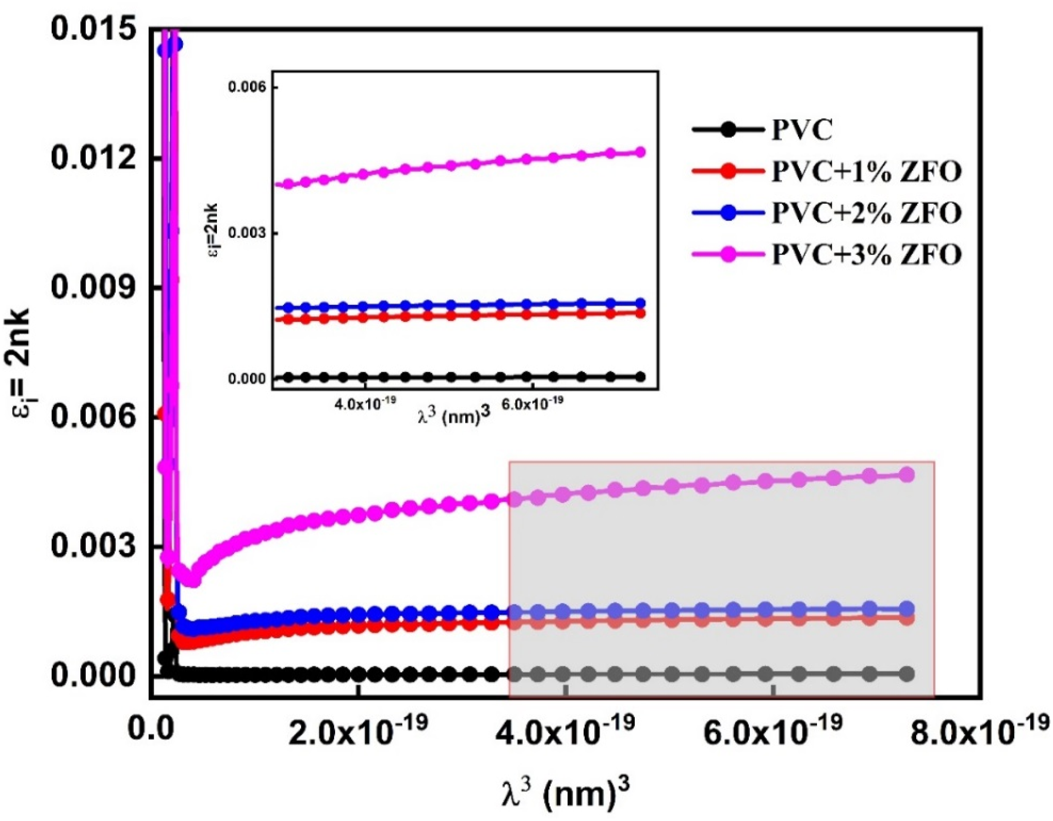
The imaginary part of the dielectric constant (εi) can be given in the Drude model utilizing the following relationship
62
: The relation between 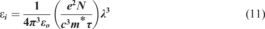
Meanwhile, in Drude model also, we can calculate the optical mobility (µopt) and optical resistivity (ρopt) using the following expressions (See Table 3)
63
:

It can be seen that values of optical mobility increase after insertion the ZFO-NPs. In which, the optical mobility increases from 8.73 × 10⁻⁴ .c.s.kg−1 for the pristine PVC to 4.87 × 10⁻², 2.26, and 0.37 c.s.kg−1 of the PVC+1% ZFO, PVC+ 2% ZFO, and PVC+3% ZFO, respectively. In contrast, the optical resistivity of the pristine PVC is 0.275, which decreases to 3.1 × 10⁻⁹, 4.78 × 10⁻¹⁰, and 2.72 × 10⁻⁹ c−2.s−1kg−1 for the PVC+1% ZFO, PVC+ 2% ZFO, and PVC+3% ZFO, respectively.
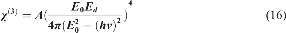
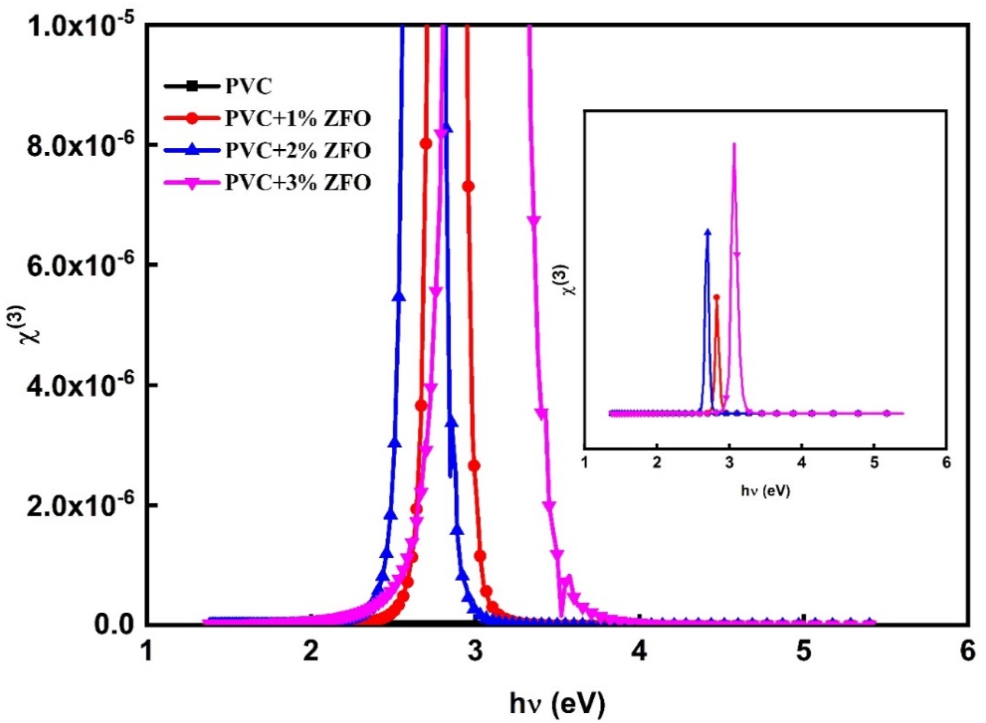
The non-linear optical (NLO) responses of the studied films can be denoted through the following expression
64
: The relation between (
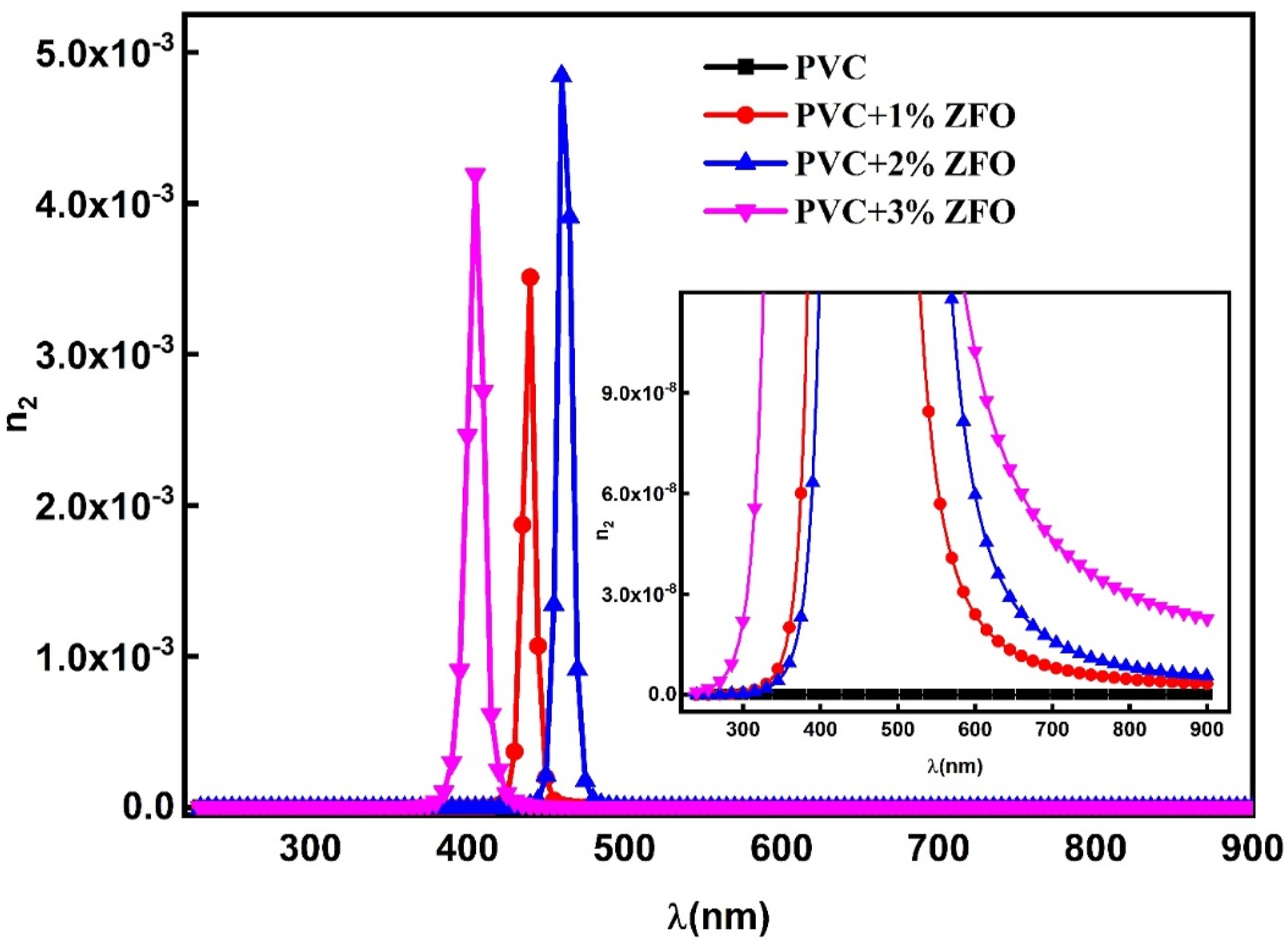
Besides, the NLO refractive index (n
2
) can be computed from values of ( The relation between (n
2
) as a function of hν for the pristine PVC and the doped films with ZFO-NPs.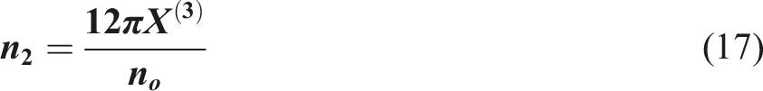
Conclusion
This study aimed to use the solution casting process to prepare PVC/ZnFe2O4 nanocomposites and study their structure and linear and nonlinear optical characteristics. The ZnFe2O4 ZFO-NPs with various concentrations (0, 1, 2, and 3 wt.%) were mixed with PVC matrix. XRD patterns and FTIR spectra confirmed the successful preparation of PVC/ZFO nanocomposites. The significant absorbance in the doped films’ ultraviolet (UV) region makes them well-suited for applications requiring ultraviolet shielding. The optical bandgap dropped from 4.14 eV to 3.88 eV, while Urbach’s energy values rose from 0.82 eV to 2.04 eV with increasing ZFO-NPs concentrations.
The free carrier increased after the introduction of the nano-ZFO. It was found that the oscillator energy values were reduced with the increasing contents of ZFO-NPs, and the dispersion energy significantly increased after the insertion of the ZFO-NPs. Furthermore, the optical mobility increases while the optical resistivity decreases with increasing ZFO-NPs contents. Additionally, the effect of ZFO-NPs on the third-order NLO susceptibility and NLO refractive index (n 2 ) was addressed. The results demonstrated that the ZFO-doped PVC films are more suitable for optoelectronic devices, including laser systems, frequency conversion, and optical switching applications.
Footnotes
Acknowledgements
The authors extend their appreciation to the Deanship of Scientific Research at Northern Border University, Arar, KSA for funding this research work through the project number “NBU-FFR-2024-3049-05.
Declaration of conflicting interests
The author(s) declared no potential conflicts of interest with respect to the research, authorship, and/or publication of this article.
Funding
The author(s) disclosed receipt of the following financial support for the research, authorship, and/or publication of this article: This work was supported by the Northern Border University; NBU-FFR-2024-3049-05.
Data availability statement
All data generated or analyzed during this study are included in this published article.