
Abstract
Throughout their service life, composite materials may be subjected to impact loads, which can result in some damage mechanisms that cause degradation in mechanical and dynamic responses. Especially matrix-induced cracks and delamination can have significant effects on the final properties, and cause serious problems if the necessary precautions are not taken. In the current study, Carbon Fiber-Reinforced Polymer (CFRP) composites interleaved with Fine Glass (FG), Polyetherimide (PEI), Polyetheretherketone (PEEK), Polyimide (PI) and Poly-Phenylene Sulphide (PPS) thermoplastic veils were fabricated, and exposed to LVI tests under 25.2 J constant impact energy to determine how veils affect the dynamic properties. The selected veils are commercially available materials and are used for various purposes. In this regard, it was aimed to examine the usability of these commercially available veils as interlayers and to examine the impacts of the veils used as interlayers on the LVI characteristic of CFRP composites. According to the present study, it was found that veil interleaves significantly affect the composite stiffness, and accordingly, relevant LVI responses such as total impulse, bending stiffness, interaction times etc. For instance, approximately 21.2% reduction in the peak displacement and 73.23% increment in the bending stiffness were observed due to FG veil interleaves. On the other hand, when the effects of veil types were examined, the maximum and minimum variations in the LVI responses were observed for the FG and PEI interleaves, respectively, and FG veils were found to be the most effective veil types for the CFRP composites. It was also revealed that veil interleaves strengthen the interlaminar region between plies and delamination resistance, and thereby improved the Delamination Threshold Loads for all configurations.
Keywords
Introduction
Over the course of their service life, fiber-reinforced composite (FRC) structures may be exposed to low-velocity impact (LVI) events, which frequently result in internal damages such matrix cracking, fiber/matrix debonding and fiber breakage.1–9 Therefore, it is extremely important to reduce the damage caused by LVI loadings by enhancing the impact resistance of FRCs. The severity of LVI-induced damages depends on many parameters such as stacking sequence, fabric architecture, impactor shape etc. 1 Kim 3 mentioned many parameters to improve impact resistance in composite structures, such as a tough matrix that provides enhanced damage resistance with a decrement in stiffness and compressive strength in hot-wet conditions, interspersed strips at delamination-prone interfaces, woven fabrics instead of cross-plies, stitch along the thickness, etc. Enhancing the fracture toughness, decreasing the damaged area, and raising the residual strength of the composites subjected to LVI loadings are the primary goals of all the aforementioned techniques. Greve and Pickett 5 introduced a modeling technique that allows impact analysis of large-scale composite structures while accounting for the occurrence of delamination. They carried out comprehensive experimental testing to ascertain the delamination failure in a non-crimped fabric/epoxy resin system. They consequently found that the results of their simulations based on static material attributes and the dynamic experimental results agreed well. Cantwell et al. 6 performed LVI tests on 16 layers of woven and non-woven carbon fiber reinforced composites. They reported that the introduction of a woven fabric enhanced impact resistance, but non-woven composites are susceptible to impact loadings. Hirai et al. 8 carried out LVI and compression after impact (CAI) tests on vinyl-ester matrix composites reinforced with woven E-glass fabric to assess the effect of temperature on LVI and CAI responses. It was stated that damage severity changed depending on the temperature variation during the impact tests, and the damaged area increased with ascending temperature.
It is highly important to detect invisible damages such as matrix cracks that occur in fiber-reinforced polymer composites. 10 Cost-effective, accurate, fast, and non-destructive testing procedures are required to detect such damages at an early stage and thus to take necessary precautions and to extend the service life of composite structures. 11 Among these, the non-destructive vibration test is one of the most widely used methods to determine the damage-induced change in material properties. 12 The fundamental idea behind this approach is that a structure’s physical characteristics, like as mass, damping, stiffness, etc., affect how a structure vibrates. Thus, measurable variations in vibration response resulting from damage-induced physical property degradation or improvement can function as a structural integrity indicator. The presence of delamination, in particular, affects the strength and vibration response of composite structures. Polimeno and Meo 13 presented two non-destructive testing approaches based on monitoring the nonlinear elastic material behavior of the damaged structures. These techniques are nonlinear wave modulation spectroscopy (NWMS) and single-mode nonlinear resonance ultrasound (NRUS). The first approach was based on the observation of the resonance frequency caused by an increment in the excitation amplitude and thus the structural response amplitude. On the other hand, the second approach is based on the observation of the harmonics and sidebands’ presence in the signal spectrum produced by a two-tone signal. As a consequence, it was noted that the presence of delamination on the composite structures could be detected even in a small area. Coskun et al. 14 carried out an experimental investigation in a different work to explore the vibration responses of epoxy composites reinforced with polyamide fibers following LVI loadings. The study’s findings showed that the composite specimens’ high matrix volume percentages were triggered by the polyamide fabrics’ architecture, which enhanced the fiber-resin interface’s damping capabilities. Through the use of polyamide fabric, a particular damping capacity of about 11.5% has been achieved.
In composite structures, using thermoplastic plies as interleaves is an effective way to absorb impact energy and improve interlaminar toughness. Therefore, many studies have been conducted to determine how veils inclusion or thermoplastic laminates affect the structural responses.15–28 In the study conducted by Tsotsis, 15 the interlayer toughening mechanism of composite materials was examined. In this context, nonwoven veils were preferred as interlayer materials and the effects of the interlayer material on compression-after-impact and unnotched-compression responses were experimentally examined. Moreover, C-Scans tests were carried out to determine the impacts of the interlayer material on the damaged area. According to the study, it has been proven that the utilization of nonwoven veils provides excellent toughening to the composites. It has also been stated that the damaged area was reduced thanks to nonwoven veil interleaves, and mechanical properties were improved by choosing the appropriate veil material. Since thermoplastic veils incorporated as interleaves in composite materials do not significantly change system permeability, which is crucial in resin infusion processes such as Resin Transfer Molding (RTM), Vacuum-Assisted Resin Infusion (VARI), and Vacuum-Assisted Resin Transfer Molding (VARTM), the utilization of thermoplastic veils allows to obtain homogeneously hardened composite structures. Moreover, the thermoplastic veil interleaves significantly increase the residual compressive strength after impact loadings by reducing the damaged area.17,18 Nejhad and Majidi 20 performed LVI tests to determine the impact performance and damage tolerance for the film-stacked, woven carbon fiber-reinforced PEEK and PPS composites. As a consequence, it was concluded that Carbon fiber PPS panels exhibited high perforation resistance. It was also determined that the comparatively smaller decrease in residual compressive strength was caused by the carbon/PEEK panels’ ability to absorb energy without substantial delamination and thus, have a smaller damage area. Nash et al. 21 studied post-impact responses of the carbon fiber/benzoxazine composites with thermoplastic veil interleaves. In this study, composite specimens with 4 types of laminate configurations as B-type (without PA veils), M-type (PA veils in the middle plane), T-type (PA veils on the first, middle and last interface) and A-type (PA veils on all interfaces) were exposed to LVI tests under 30 J energy, and was found that the damaged area was reduced up to 36% for A-type and 24% for T-type thanks to PA veil inclusion.
Quan et al. 23 incorporated PEEK veils as an intermediate laminate into carbon fiber/epoxy composites using the UV irradiation technique. As a consequence, it has been shown that a significant improvement in the adhesion performance of carbon fiber/epoxy composites with PEEK interleaves was achieved thanks to UV treatment, thereby increasing the final strength from 0.6-0.7 MPa to 7.6 MPa. In the study conducted by Quan et al., 25 PEEK thin films with various thicknesses were utilized as interlayer material in carbon/epoxy composites, and then mode-I and mode-II fracture behaviors were examined. According to the study, an increment by about 227% and 441% in mode-I and mode-II fracture energies, respectively, was achieved thanks to PEEK thin films. Moreover, UV-irradiation was applied to PEEK films, and it was determined that the applied process significantly rise the adhesion between PEEK interlayers and composite matrix. In a similar study, 26 the impacts of thermoplastic nonwoven veils on the fracture energy and toughening mechanisms of composites under mode-I loading were examined. In this context, two different veils, PEI and PPS, were used as interlayer materials and then double cantilever beam tests were carried out. In this way, 13% and 60% improvement in fracture energy responses was achieved with PEI and PPS additives, respectively. It has also been stated that thermoplastic veil interleaves are quite effective in ascending delamination resistance. In another study conducted by Quan et al., 27 the effects of hybrid meltable/non-meltable thermoplastic veils on the fracture toughness responses of carbon fiber-reinforced epoxy composites were experimentally examined. In the relevant study, it was stated that while the toughening mechanism for non-meltable veils is fiber bridging, it is matrix toughening for meltable veils. According to the study, it was stated that mode-I and mode-II fracture energies increased by 273% and 206%, respectively, thanks to veil interleaves. It was also concluded that the compatibility between epoxy matrix and veils is an important factor affecting toughening levels and mechanisms. In another study, 28 the impacts of PPS and PEEK thermoplastic veils on the mode-I and mode-II interlaminar fracture toughness of carbon fiber-reinforced composites were examined. Furthermore, the effects of fiber diameters of thermoplastic veils on fracture responses were examined, and it was concluded that the mode-I fracture toughness responses of thin fibers were higher compared to thicker ones. It was also concluded that areal density has no effect on network porosity and anisotropy.
When the studies in the literature are examined, it is clear that the influences of veil interleaves on LVI responses are limited. Furthermore, it seems that the effects of FG, PEEK, PEI, PI and PPS veil types on LVI responses have not been examined together in the previous studies. For that reason, various of nonwoven thermoplastic veils, namely FG, PEEK, PEI, PI and PPS, were used as interlayers, and the veil interleaves effects on LVI responses were experimentally determined. In this regard, besides the dynamic characteristics such as force-time curves, bending and contact stiffness, peak force and absorbed/rebounded energies, the affects of using a thermoplastic veil on the Delamination Threshold Loads have been scrutinized and contributed to the literature. Moreover, SEM analyses for the specimens which entirely consist of thermoplastic veil laminates were carried out and microstructures of specimens were examined.
Material and Methods
For the reinforcement material, 12k plain-woven carbon fabrics with an areal density of 500 g/m2 were used, while thermoset Epoxy was used as the resin system. The resin system, which included Duratek DTE 1120 Epoxy and DTS 1151 Hardener, was provided by Duratek firm, while the plain-woven carbon textiles were obtained from Carbomid incorporated firm (Istanbul, Turkey). Additionally, PI, PEI, PEEK, FG and PPS nonwoven veils with areal densities of 8 g/m2, 10 g/m2, 10 g/m2, 10 g/m2 and 20 g/m2, respectively, were utilized as interleaving materials supplied by Technical Fibre Products Ltd (Cumbria/UK). In this manner, CFRP composite materials with and without thermoplastic veils inserted into intermediate layers were manufactured and the effects of veil utilization on LVI responses were investigated. The 12k plain-woven carbon and non-woven thermoplastic veils used for specimen preparation are shown in Figure 1. Moreover, some details for the various thermoplastic veils are shown in Table 1. Representation of the plain-woven carbon and non-woven thermoplastic veil fabrics. Some details for the thermoplastic veils.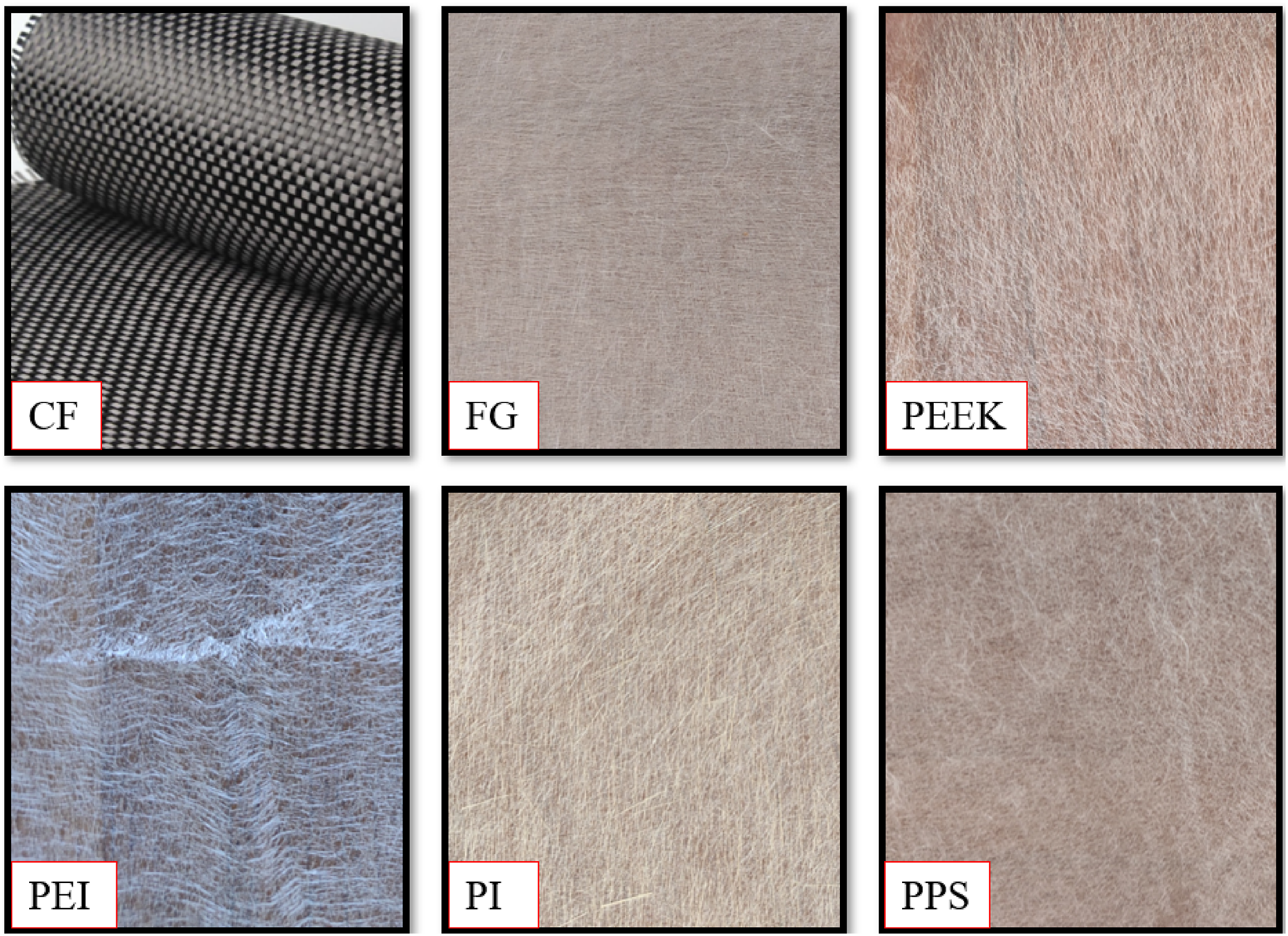
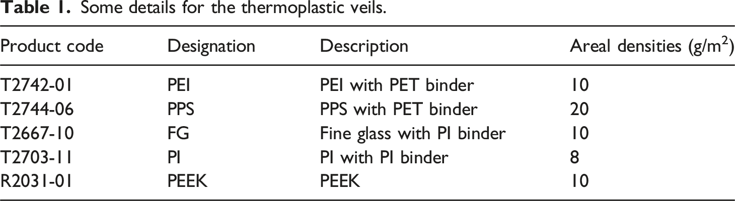
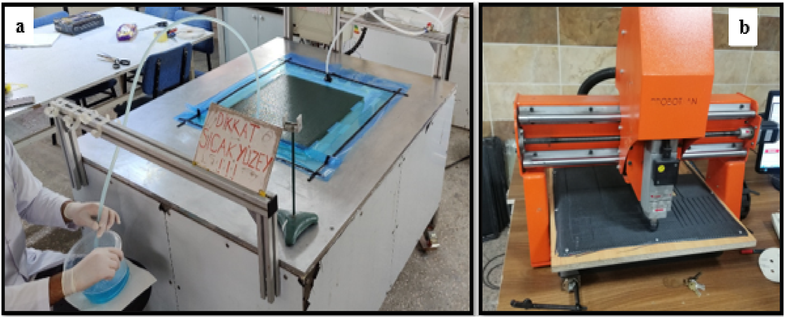
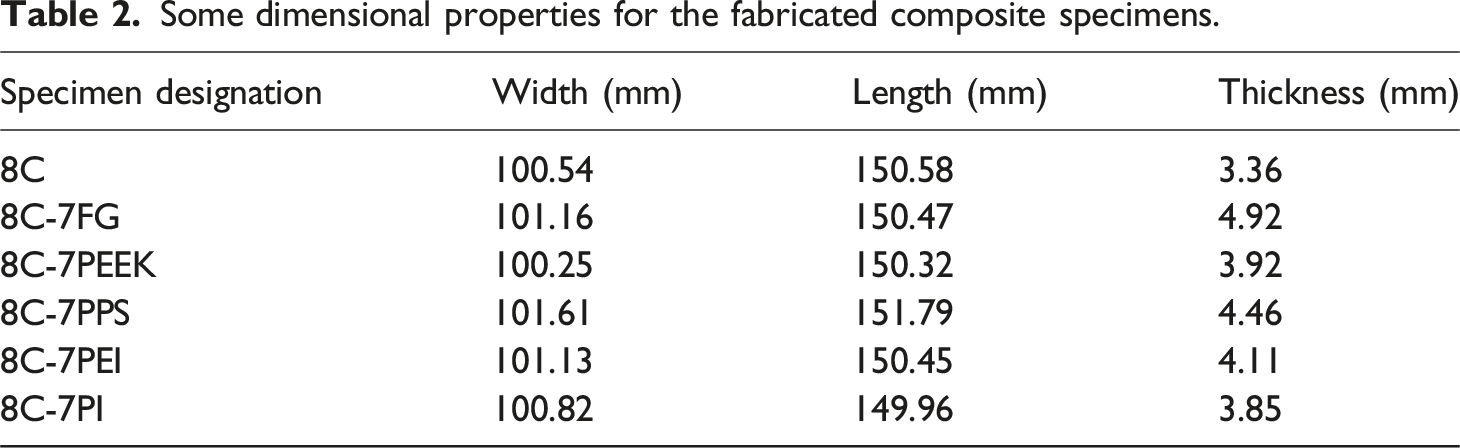
Figure 2 depicts the Vacuum Assisted Resin Transfer Molding (VARTM) technique utilized in the production of composite specimens. To achieve a homogeneous mixture, thermoset DTE 1120 Epoxy resin and DTS 1151 hardener were blended in a 27% weight percentage for 5 minutes by using a mechanical mixer at 500 rpm. Furthermore, vacuum degassing was employed to remove air bubbles formed throughout the blending process, and the resulting resin was infused into thermoplastic veils and synthetic textile composite laminates. Upon being put on the temperature-controlled panel demonstrated in Figure 3(a), the composite laminates underwent curing at 100°C for 8 h. The composites were then manufactured as plates and cut in 100 × 150 mm size in line with the ASTM D-7136 standard, as shown in Figure 3(b). Some dimensional properties such as width, length and thickness for the composite specimens are shown in Table 2. In the current study, although void content was not clearly stated, a homogenous mixture and vacuum degassing were used to reduce void content throughout the resin infusion process. Furthermore, it was determined from the SEM visuals that the fabricated composites had quite low void content. On the other hand, in the current study, fiber mass fractions (FMF) were examined before manufacturing instead of fiber volume fractions (FVF). In this regard, the matrix and fiber weights were determined, and thus composites were fabricated with approximately 70% fiber and 30% resin FMF. A schematic representation of the production process for composites. Illustration of the composite fabrication (a) and machining (b) processes. Some dimensional properties for the fabricated composite specimens.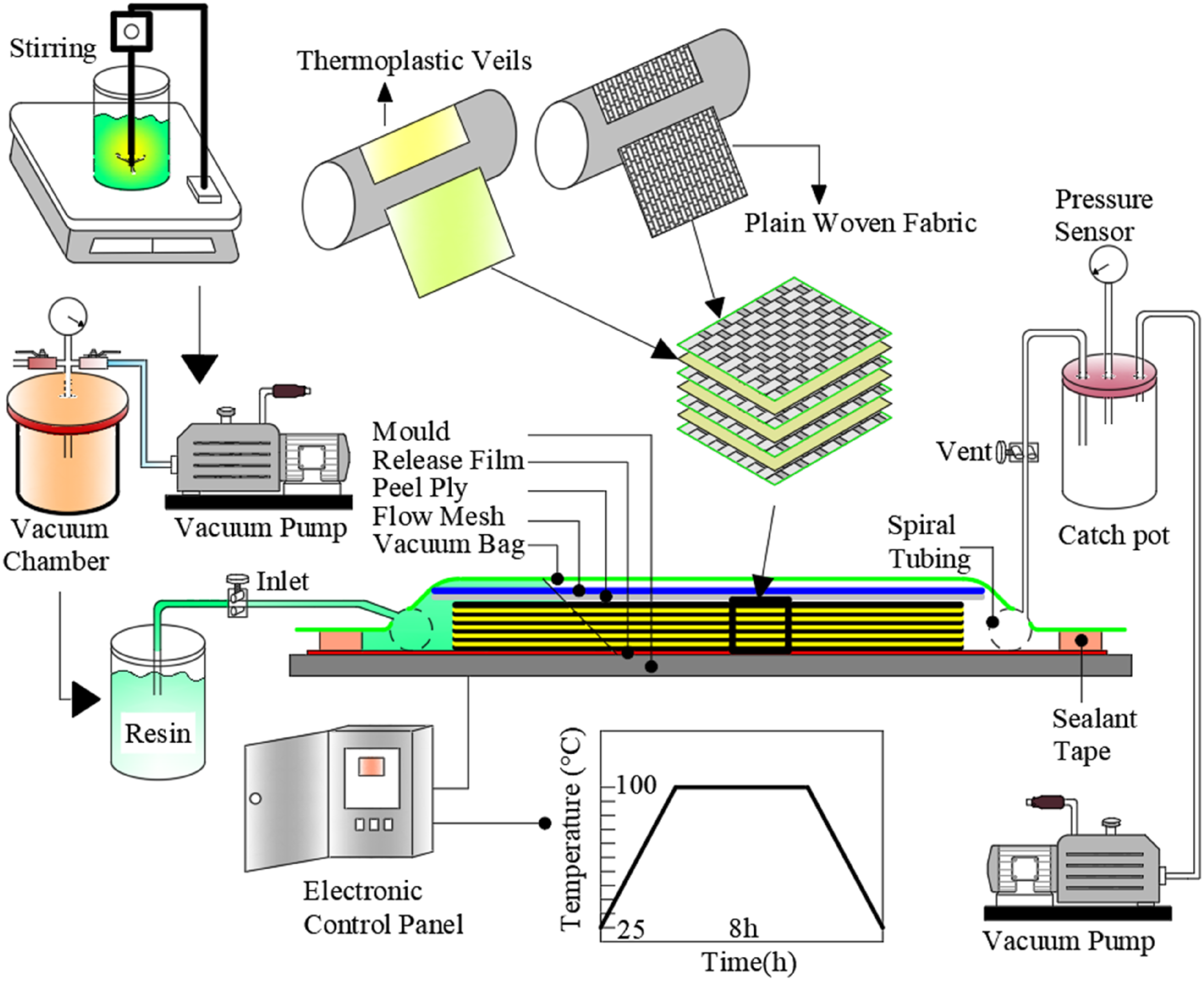
Some details for the test specimens.
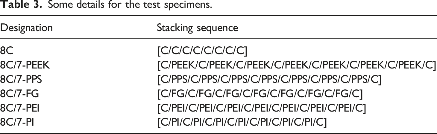
Figure 4 depicts an experimental setup for drop-weight testing used to examine the LVI responses for CFRP with veil interleaves. In the experiments, a 5.6 kg impactor with a hemispherical tip was released from 45.87 cm height, resulting in impact loadings with 3 m/s velocity and 25.2 J energy to the center of the composite specimens. When LVI applications in the literature are studied, it is found that the tests are often performed at velocities ranging from 1 to 10 m/s.
29
In the current study, an impact velocity of 3 m/s, equivalent to 25.2 J energy, was preferred due to the application areas, the brittle nature of synthetic fiber and epoxy, and typical drop events. During the impact loadings, a certain amount of the applied energy is absorbed by the specimens, and then the residual energy is transferred back to the impactor, causing it to gain potential energy again. This process continues until all energy is absorbed by the specimens, which ensures that multiple impacts are performed and the LVI responses cannot be detected accurately. Therefore, the anti-rebound system is used in the experimental set-up to prevent multiple impacts. In the anti-rebound system, the pneumatic pistons are immediately opened thanks to the level sensor after the first impact, and thus repeated impacts are prevented. Apart from that, force-time data are achieved using a data acquisition system consisting of an accelerometer, data logger and software, and then obtained curve data are processed using Excel subroutine to achieve LVI results such as contact/bending stiffness, absorbed/rebounded energy, peak displacement/force etc. Drop-weight tests were conducted on a minimum of three samples for each configuration, and standard deviations were determined to make sure that the results were accurate and reproducible. The schematic representation of the drop-weight test experimental setup.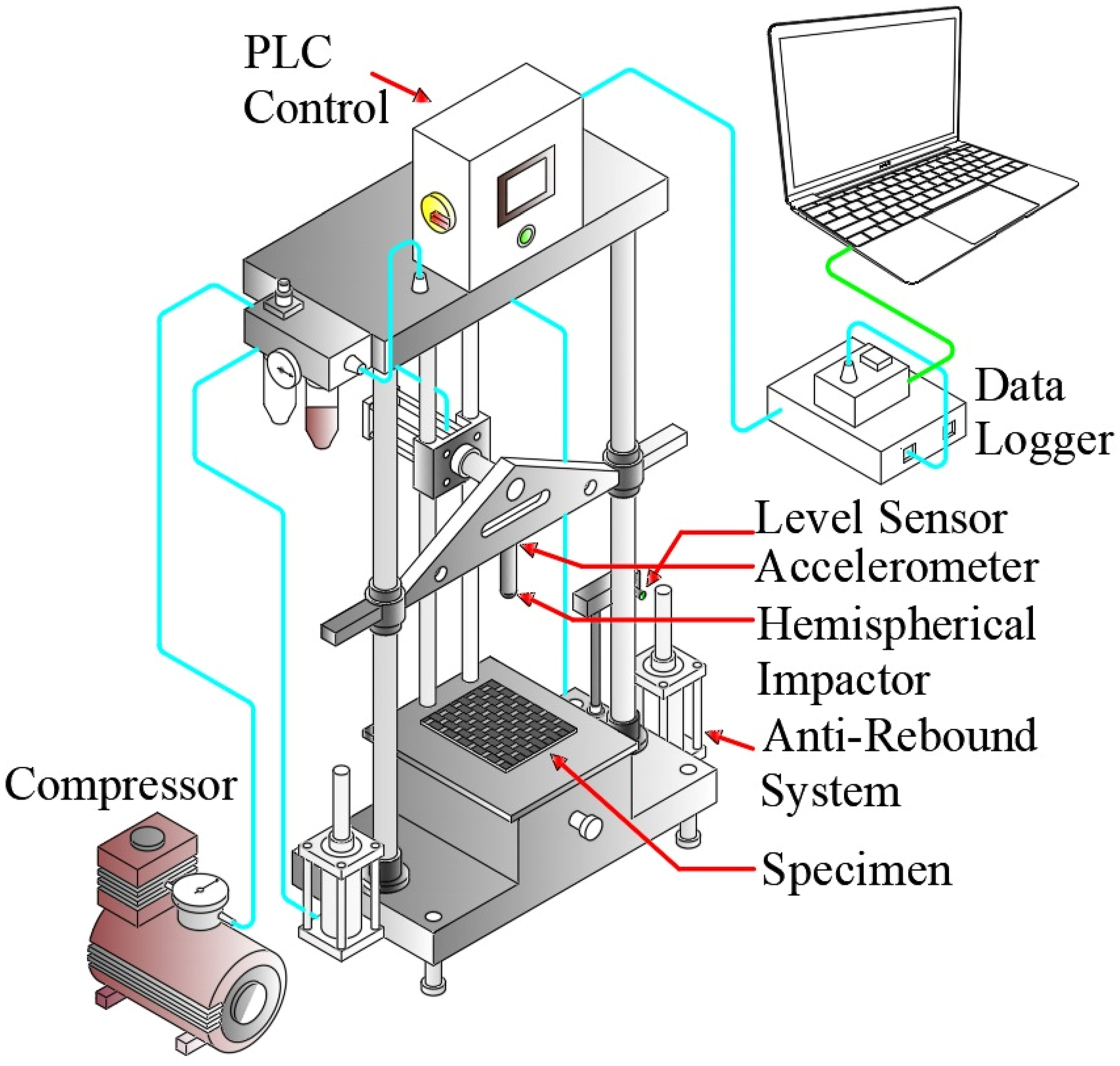
Results and Discussions
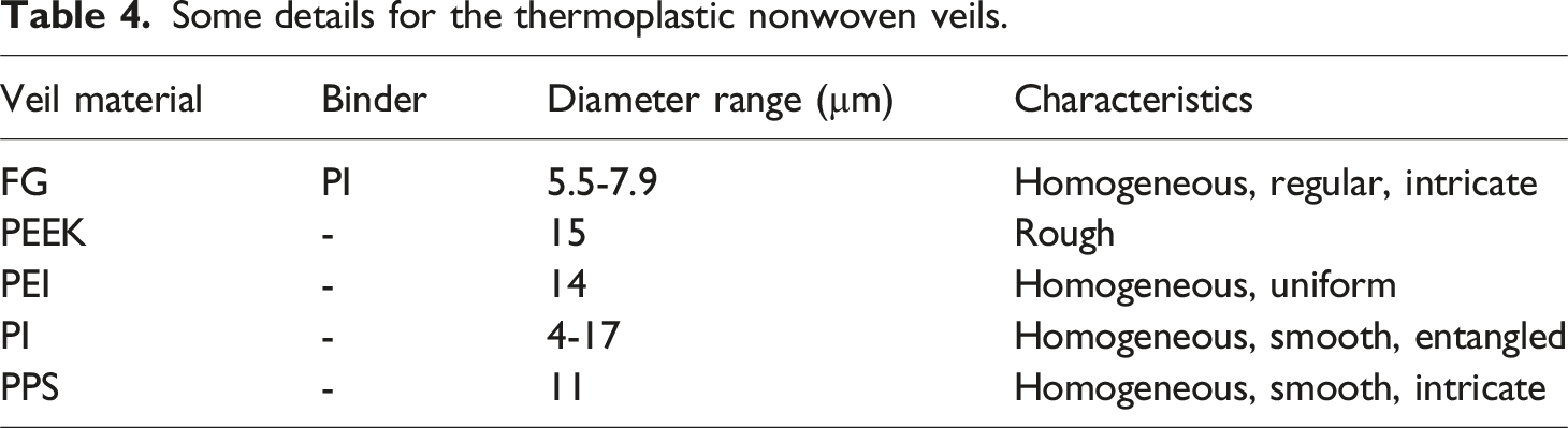
SEM images of PEI, FG, PEI, PPS, PEEK and PI veils with varying diameters are shown in Figure 5. The structure of glass with PI binder is homogeneous, regular, and intricate, with diameters ranging from 5.5 µm to 7.9 µm (Figure 5(a)–(c)). The diameters of PEEK veils are around 15 µm and surface of PEEK veil fibers has rough structure (Figure 5(d)–(f)). The structure of PEI with diameters of around 14 µm veils is homogeneous and uniform (Figure 5(e)–(i)), Furthermore, there are little dots on the surface of the PEI veil fibers that will increase the surface roughness. As for the structure of PI veils (Figure 5(j)–(l)), they are homogeneous, smooth and entangled against each other and their diameters vary between 4 µm and 17 µm and it is seen that there are small spots on the surface of the same PEI veil fiber. Finally, PPS veils have a homogenous, smooth, and intricate structure, and their diameter is approximately 11 µm. The mentioned details are summarized in Table 4. SEM image of the various interleave (a-c) FG, (d-f) PEEK, (g-i) PEI, (j-l) PI and (m-o) PPS. Some details for the thermoplastic nonwoven veils.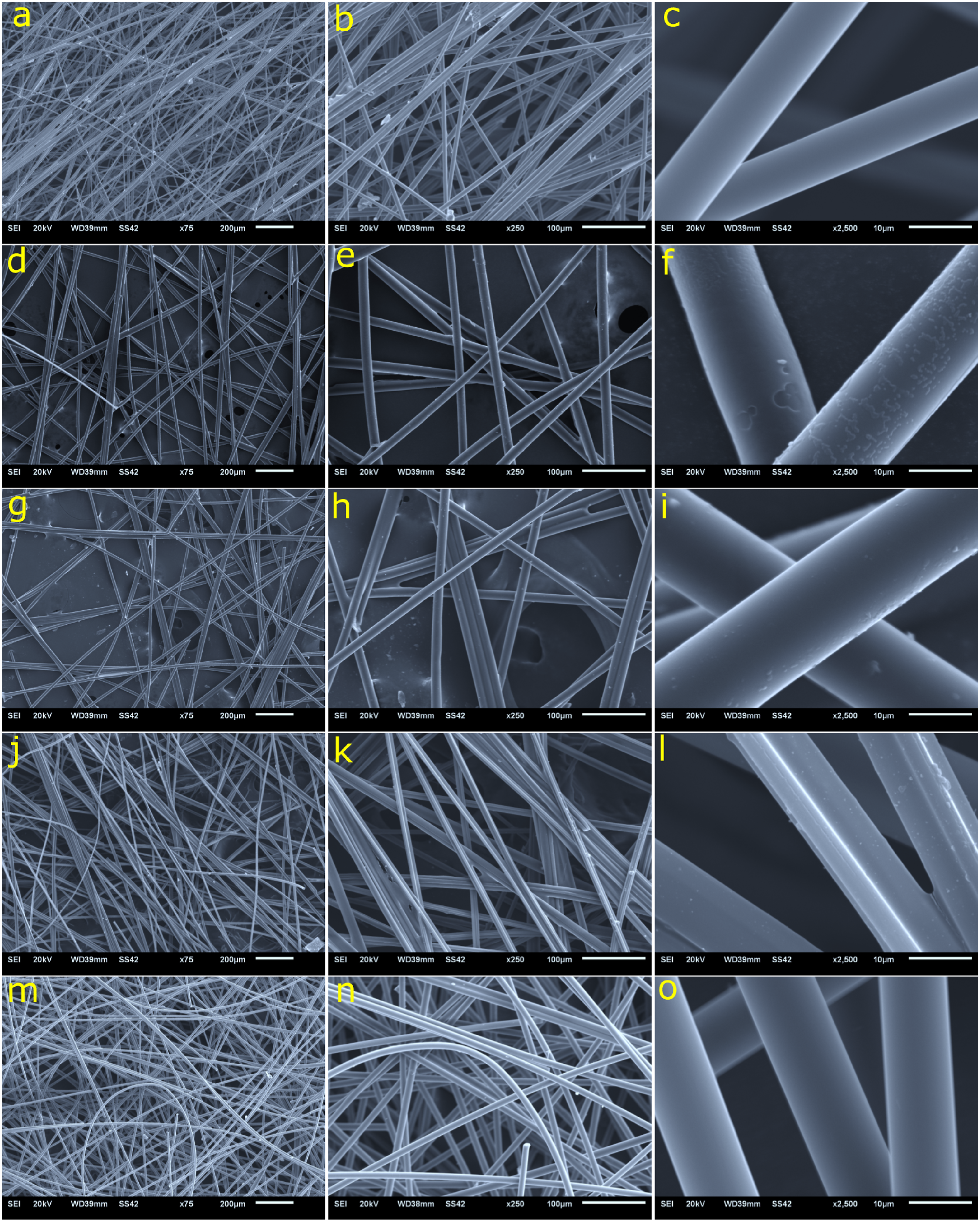
The current study employed an impact energy of 25.2 J to evaluate the impacts of different veil interleaves for the LVI characteristics of carbon fiber-reinforced epoxy composites. In this context, the contact force-time results for the 8 plies of CFRP composites were compared with CFRP composites with FG, PPS, PEEK, PEI and PI veil interleaves, and are shown in Figure 6. It is well-known that these curves provide valuable information to evaluate the dynamic characteristics of the composites such as interaction time, contact stiffness, peak force, delamination threshold load etc. For instance, the contact stiffness for the composites can be determined from the slope of the force-time curves.
30
It was revealed from the curves that all carbon/epoxy composites interleaved with thermoplastic veils exhibited higher contact stiffness than 8 plies of CFRP composites, and this indicates that specimens gain stiffness thanks to thermoplastic veil interleaves. The contact force-time graphs of CFRP composites and CFRP composites with FG, PEEK, PI, PEI, PPS veil interleaves.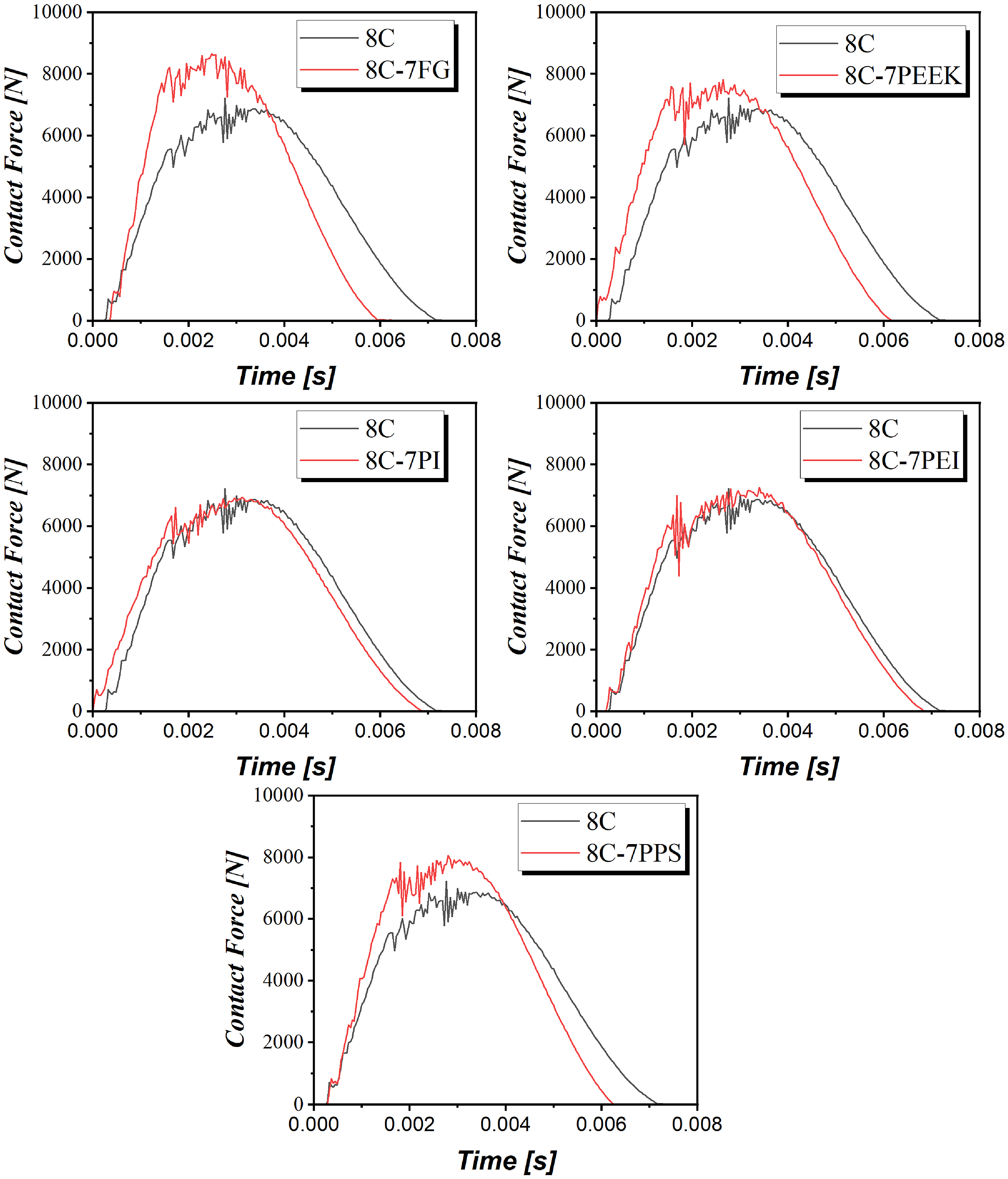
When the interaction times were taken into consideration, it is possible to describe as the time needed for elastic and plastic deformations during the impact loading. 31 Since the time necessary for elastic deformation is mostly similar for all samples, a longer interaction time usually indicates more plastic deformation. The results revealed that all forms of veil interleaves lowered contact times and thus plastic deformation within this limit. On the other hand, Delamination Threshold Load (DTL), which can be defined as the first significant sudden load drop, 32 were examined for the various veil interleaves, and it was found that DTL points were increased thanks to veil interleaves for all configurations. Moreover, it was observed that magnitude of the sudden load drops after DTL points were reduced for the FG, PPS and PI veil interleaves. This stated that overall delamination magnitudes were reduced and stable damage propagation was achieved thanks to veil interleaves.
The fluctuations and sudden force drops on the curves can be used to evaluate damage severity. 33 From the force-time graphs, it is apparent that sudden load drops and fluctuations become more pronounced with veil interleaves for all configurations, and the magnitude of sudden load drops significantly changed, especially for PEEK and PEI veil interleaves. It indicates that more damages such as indentation, delamination and fiber rupture took place on the specimens due to increased contact stiffness. It can also be seen from the curves that the contact forces for all configurations go up to the peak during the loading phase, and then the residual energy is transferred to the impactor throughout the restoration cycle. Here, force-time graphs were observed to be entirely closed, indicating that the composite specimens were not entirely penetrated despite the damage.
Figure 7 demonstrates comparisons of the influence of the PPS, FG, PEEK, PI and PEI veils on the LVI responses of Carbon/Epoxy composites. According to the findings, the veil interleaves had a considerable effect on the contact stiffness and consequently the peak forces of the composite specimens. It has been observed that the thermoplastic veil interleaves increased the contact stiffness and peak forces. The carbon/epoxy composites interleaved with PEI veils showed the lowest contact stiffness and peak forces, whereas the composites with FG, PPS, PEEK, and PI veil interleaves showed the highest ones. These results were attributed to the fact that thermoplastic veils strengthen the fiber-matrix interaction and increase the delamination resistance for all laminates,
34
thereby causing the veil interleaves composites to gain contact stiffness. Based on this, it can be stated that FG interleave is the most effective veil type in terms of improving the delamination resistance, while PEI veils do not have remarkable effects on the fiber-matrix interactions. The contact force-time graphs for the Carbon/Epoxy composites with FG, PEEK, PI, PEI, PPS veil interleaves.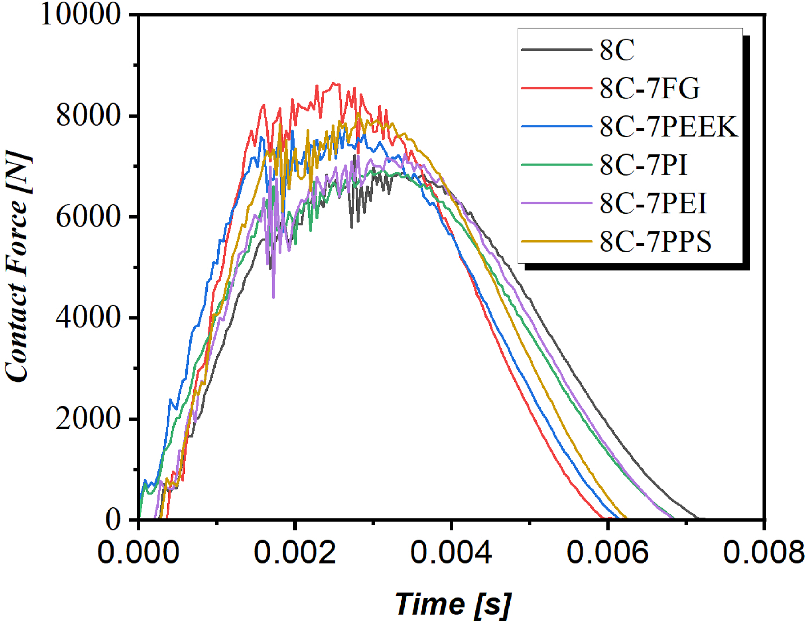
On the other hand, when the interaction times were compared, it was concluded that the results were compatible and supported by the contact stiffness and peak force responses. In contrast to contact stiffness, CFRP composites interleaved with PEI veils had the longest interaction times, whilst FG, PPS, PEEK, and PEI composites had the shortest, respectively. This was expected and was attributed to the fact that increasing stiffness reduces the amount of plastic deformation and thus the interaction time. Apart from that, it turned out that the veil interleaves increased the severity of the fluctuations. It is clear from Figure 7, the lowest fluctuations severity was observed for PEI veils, while the highest fluctuations took place in composites interleaved with FG veils. Similarly, this was attributed to the ascending stiffness, and hence it was concluded that thermoplastic veil interleaves increased the damage severity.
Figure 8 demonstrate the LVI responses such as total impulse, peak displacement, interaction time, peak forces, contact/bending stiffness for the composites. In the current investigation, LVI tests were carried out on at minimum 3 samples from each configuration, and standard deviations were determined to make sure findings were credible and reproducible. Within this scope, it was found that standard deviations were reasonable, and experimental results were reliable and repeatable. When the results were investigated, it is clear that total impulse, peak displacement and interaction times exhibited similar trends. For all these three behaviours, maximum responses were achieved for the 8 plies of CFRP composites, while minimum ones were observed for the composites with FG veil interleaves. For instance, maximum and minimum peak displacements were calculated as 6.6 and 5.2 mm, respectively, and approximately 21.2% reduction in the peak displacement were observed due to FG veil interleaves. Similarly, maximum and minimum total impulses were calculated as 4470.97 and 3512.21 N.s, and 21.44% reduction were obtained due to FG veils. All these outcomes are expected, and the reductions in total impulse, peak displacement and interaction times are attributed to the fact that these responses vary inversely with the specimen stiffness. These findings are also related to both the veil interleaves effect and the composite samples’ varying thicknesses. As thickness rises, so does material stiffness, resulting in a reduction in LVI responses such as peak displacement and total impulse. Total impulse, peak displacement, contact/bending stiffness, interaction time and peak force responses for the Carbon/Epoxy and Glass/Epoxy composites with FG, PI, PPS, PEEK and PEI veil interleaves.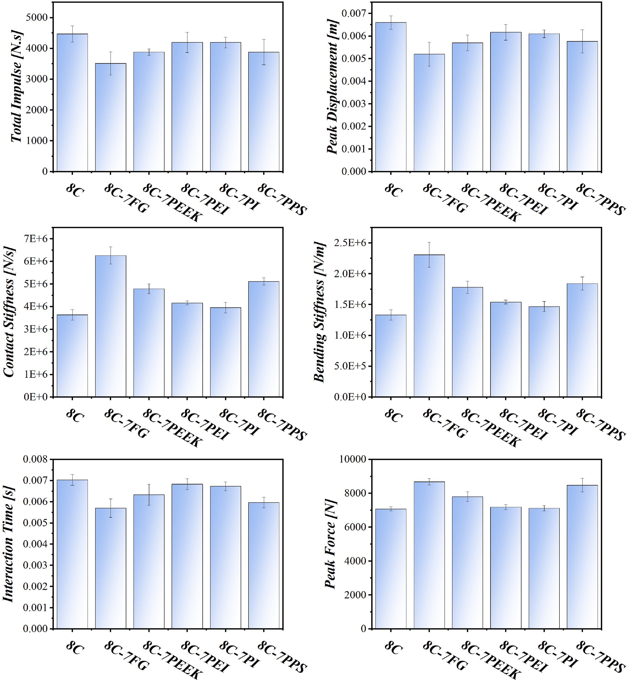
The opposite trend was observed for the peak force, contact stiffness and bending stiffness responses relative to peak displacement, total impulse and interaction times. This was also expected because every type of thermoplastic veil additive caused a rise in specimen stiffness as mentioned in the previous paragraphs, and these responses generally increase with the ascending stiffness. For instance, it is clearly seen that bending stiffness, which can be described as the slope of the force-displacement graphs, 35 for all configurations were significantly affected thanks to thermoplastic veil interleaves. FG veil additive caused an about 73.23% increase in the bending stiffness, while minimum bending stiffness was found for the 8 plies of Carbon/Epoxy composites. Similarly, maximum and minimum contact stiffness were observed as 6264.4 and 3639.2 kN/s, and approximately 72.14% increment in the contact stiffness was obtained thanks to FG veils. In addition to the veil interleaves effect, as in peak displacement and total impulse responses, higher composite thicknesses also raise stiffness responses. For example, the highest stiffness responses were observed for the thickest 8C-7FG composites, while the lowest stiffness responses were observed for the 8C composites with the lowest thickness. On the other hand, although the thickness of 8C-7PEEK composites is lower than that of 8C-7PEI ones, the fact that 8C-7PEEK composites exhibit higher stiffness shows that PEEK interleaves are quite effective on material bending and contact stiffness responses.
The absorbed energies of the composites are demonstrated in Figure 9. In the present study, 25.2 J impact energy was performed, and absorbed energies during the impact loading were calculated. It is clear from Figure 9, more than 50% of the energies were absorbed by the composites for all configurations and Carbon/Epoxy composites with veil interleaves have been proven to be useful for industrial applications that demand high impact resistance. Additionally, it was concluded that thermoplastic veil interleaves generally increased the absorbed energy. For instance, absorbed energies for the 8 plies of CFRP composites and carbon/epoxy composites with FG veil interleaves were obtained as 13.85 and 14.39 J, respectively, and approximately 3.97% improvement has been achieved thanks to FG veil interleaves. These outcomes were explained by the thermoplastic materials’ chemical structure, which is thought to be contributing to chain slippages in thermoplastics boosting their capacity for absorbing energy.36–39 Furthermore, it is recognized that segmental movements,
40
plastic deformation,
41
and damage development
42
are the most effective mechanisms for energy absorption in composites. Given that the energy absorption due to damage developments and segmental movements in the carbon fibers and epoxy matrix, which stand out for their brittle characteristics, are the same for all composite types, it is considered that the thermoplastic veil interleaves improve the composites’ plastic deformation. Upon analysing the energy absorptions depicted in Figure 9, slight improvements in the responses are detected. This is ascribed to the marginal rise in plastic deformation resulting from veil interleaves, which thus enhances the energy absorptions. On the other hand, the highest and lowest absorbed energies for the FG and PPS veils, respectively, were found when the effects of the veil types were explored. Depending on the veil materials, a 3.67% improvement in the absorbed energy was also observed. Comparison of the absorbed energies for the Carbon/Epoxy composites with FG, PI, PPS, PEEK and PEI veil interleaves.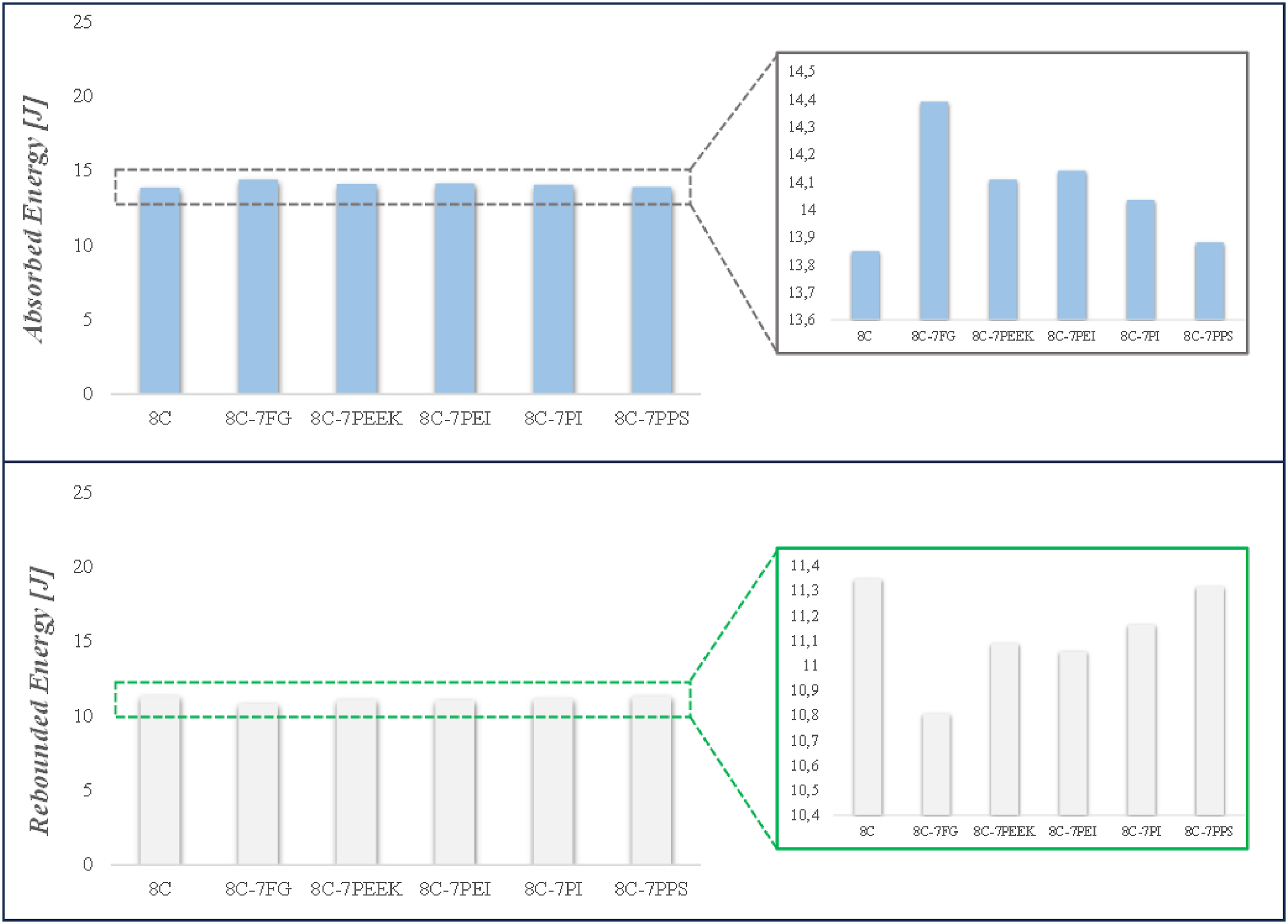
Conclusions
In the present study, LVI tests were conducted to define the impacts of FG, PPS, PEEK, PEI and PI veil interleaves in the dynamic properties of the CFRP composites. In this context, LVI responses such as force-time curves, contact stiffness, absorbed energy etc. Were obtained experimentally, and results for all configurations were compared. The following are the main findings of the current study: • The LVI responses of the 8 plies of CFRP composites were compared with CFRP composites with veil interleaves, and veil interleaves were found to be significantly effective on the dynamic properties. From the results, it was concluded that CFRP composites with veil interleaves exhibited more contact stiffness than 8 plies of CFRP composites. Similarly, an increase in bending stiffness and peak forces was observed for composites with veil interleaves, and these findings were attributable to the fact that composite specimens acquired stiffness as a result of the FG, PPS, PEEK, PEI, and PI veils. • From the results, it was found that DTL values were increased and sudden load drop magnitudes after DTL points were reduced thanks to veil interleaves. In this way, fiber-matrix interactions and thus delamination resistance were significantly improved, and stable damage propagation was achieved. • When the impacts of the veil types on the LVI results were examined, the maximum and minimum variations in the results were observed for the FG and PEI interleaves, respectively, and therefore FG veils were found to be most effective veil types on the LVI responses. Approximately 21.2% reduction in the peak displacement and 73.23% increment in the bending stiffness were observed due to FG veil interleaves. Additionally, it was observed that FG veil interleaves caused about 3.97% improvement in absorbed energy compared to 8 plies of CFRP composites.
Footnotes
Declaration of conflicting interests
The author(s) declared no potential conflicts of interest with respect to the research, authorship, and/or publication of this article.
Funding
The author(s) disclosed receipt of the following financial support for the research, authorship, and/or publication of this article: This work was supported by the Ataturk University (BAP, Project No: FBA-2021-9447) and Bingol University (BAP, Project No: BAP-MMF.2021.002).