
Abstract
Carbon fiber-reinforced thermoplastics have been extensively studied to reduce the weight of transportation equipment. In this study, to enhance the interlocking effect of Ti-6Al-4V rivets, the new riveting process combined with refill friction stir spot welding (FSSW) was attempted. Consequently, the successful combination of refill FSSW and riveting resulted in a flared trumpet-shaped rivet, expanding the diameter of its tip significantly. Tensile shear tests exhibited both the stirred zone induced by refill FSSW and the flared rivet affected the fracture behavior. The cross-sectional observations revealed the existence of cracks at the boundary between the stirred zone and base material during tensile shear tests. Furthermore, a unique arrangement of the fiber caused by the stirring action was identified by observing the fracture surface using scanning electron microscopy. The study findings clarify the advantages of combining refill FSSW with riveting, providing insights into the potential implementation of this combined process in thermoplastic composites.
Introduction
The average temperature of the Earth is consistently increasing, and greenhouse gases, such as CO2, are considered to be a major cause of global warming. According to a report related world greenhouse gas emission, the transportation sector accounts for approximately 21% of total CO2 emissions 1 In particular, the proportion of automobiles and airplanes is higher than that of other vehicles, such as railway trains. In the near future, CO2 emissions from transportation are expected to be significantly reduced through energy transformations, such as the use of hydrogen fuel in automobiles 2 and aircraft. 3 However, there exists a critical demand for a reduction in driving friction, air resistance, and weight to improve fuel efficiency.
Lightweight materials, such as aluminum, magnesium alloys, and carbon fiber-reinforced plastics (CFRPs), are essential for reducing the weight of transportation equipment. Among these, CFRP has been extensively used in aircraft fuselages, wings, and tails. To eliminate the shortage of CFRPs caused by long-term heat treatment in autoclaves, carbon fiber-reinforced thermoplastics (CFRTPs) have been actively researched for the past several decades to apply them to future aircraft fuselage structures considering high-speed production.4,5
Fastening and joining processes are an important aspect of the assembly process in the manufacture of CFRTP structures. Several studies have been reported on welding methods for CFRTP, including ultrasonic, induction, and resistance welding.6–11 Ultrasonic welding uses high frequencies to vibrate longitudinally while being pressurized with an anvil and horn to join plastics. This technique is used in multiple fields, such as the implementation of lightweight thermoplastic matrix composites in the electrical, automotive, and aircraft sectors. Induction welding involves the joining of polymer matrices using induction heating; here, eddy currents are generated by an exchanged electromagnetic field, which causes efficient local heating. In resistance welding, electrically conductive elements are placed at the interface of the parts being joined; this conductive element is typically a carbon fiber or steel mesh connected to a power source. When an electric current passes through this conductive element, heat is generated at the interface, which melts the plastic and creates a bond. This is a highly energy-efficient method with low heat loss, indicating that less energy is required to melt the matrix.
Additionally, researchers have investigated friction-based welding of CFRTP, such as refill friction stir spot welding (FSSW). 12 Unlike riveting, FSSW is a dustless process as it does not require a pilot hole. Refill FSSW is a solid-state joining method, wherein a rotating tool in the material generates frictional heat and stirs the material to form firmly joined welds.13–15 This technique has been validated and applied to certain aluminum parts of automobiles. Schäfer et al. 13 reported the optimization of parameters for defect-free joining of CFRTP and elucidated the failure mechanisms involved in the mechanical properties. However, only a few studies exist on refill FSSW in CFRTP.
Several studies have reported self-piercing rivets 16 or friction self-piercing rivets 17 as alternatives, with reports on dissimilar welding of CFRP and aluminum 18 or magnesium alloys. 19 In these cases, a CFRP sheet is set on top and a rivet is driven through the sheet. As the rivet proceeds through the metal, the diameter of the rivet tip increases; in other words, the rivet flares, firmly interlocking the upper and lower sheets. Plastic deformability of the material plays an important role in successful riveting as it can prevent defects such as cracks in the base material. Other report 20 on the welding of glass fiber reinforced polyphenylene sulfide and aluminum discusses the complex thermal-mechanical and material flow behaviors resulting from high peak temperatures and significant shear forces, which greatly influence void formation and subsequently affect mechanical properties. Additionally, novel techniques based on solid-state welding methods have been proposed and have achieved valuable results. 21 However, despite several reports on dissimilar welding of CFRP and metals, only a few studies have explored the combination of CFRPs.
Borba et al.22–24 and Altmeyer et al. 25 reported a friction rivet, which is a joining method that uses frictional heat and an interlocking effect by inserting a titanium alloy into composite materials. In this process, a metallic rivet that rotates at high speeds is pressed into thermoplastics, and the generated frictional heat softens the materials and enables the rivet to penetrate deeper. The rivet tip receives resistance from the material and is deformed to adopt a wider diameter (flaring). After consolidation under pressure, the anchoring and adhesive forces hold the joints together. 12 The aforementioned process can be adapted to the joining of CFRTP to maximize the interlocking effect of rivets by effectively enlarging the tip of the rivet via heat generation and material softening by combining the refill FSSW process.
Therefore, in this study, the possibility of combining refill FSSW with the riveting process is investigated. The basic characteristics of the joining process and failure during tensile tests are analyzed to examine the feasibility of this new process.
Experimental Procedure
Materials
The material used in the experiment was a carbon/polyphenylene sulfide (PPS) consolidated composite laminate (Tepex® Dynalite 207-C200(x)/50%). The nominal thickness of the material per layer was 0.22 mm, and the total thickness measured using a thickness gauge was approximately 1.93 mm. According to the manufacturer, the tensile modulus, strength, melting temperature, and glass transition temperature of the material were 52 GPa, 750 MPa, >280°C, and 91°C, respectively. Figure 1 depicts the dimensions of the test specimens, cut to a width of 30 mm and length of 125 mm. The characteristics of the composite material and rivet composed of Ti-6Al-4V alloy in Table 1. A lap joint configuration is applied, and the lap length is set to 30 mm in most cases. Cross-sectional observation and tensile tests were performed after welding. Figure 1 also illustrates the dimensions of the rivet. A keyway is provided at the top of the body and attached to the protrusion of the probe to transmit torque from the probe to the rivet. Dimensions of the test piece and rivet, composed of Ti-6Al-4V, used in the experiment. Properties of the composite material and rivet composed of Ti-6Al-4V alloy.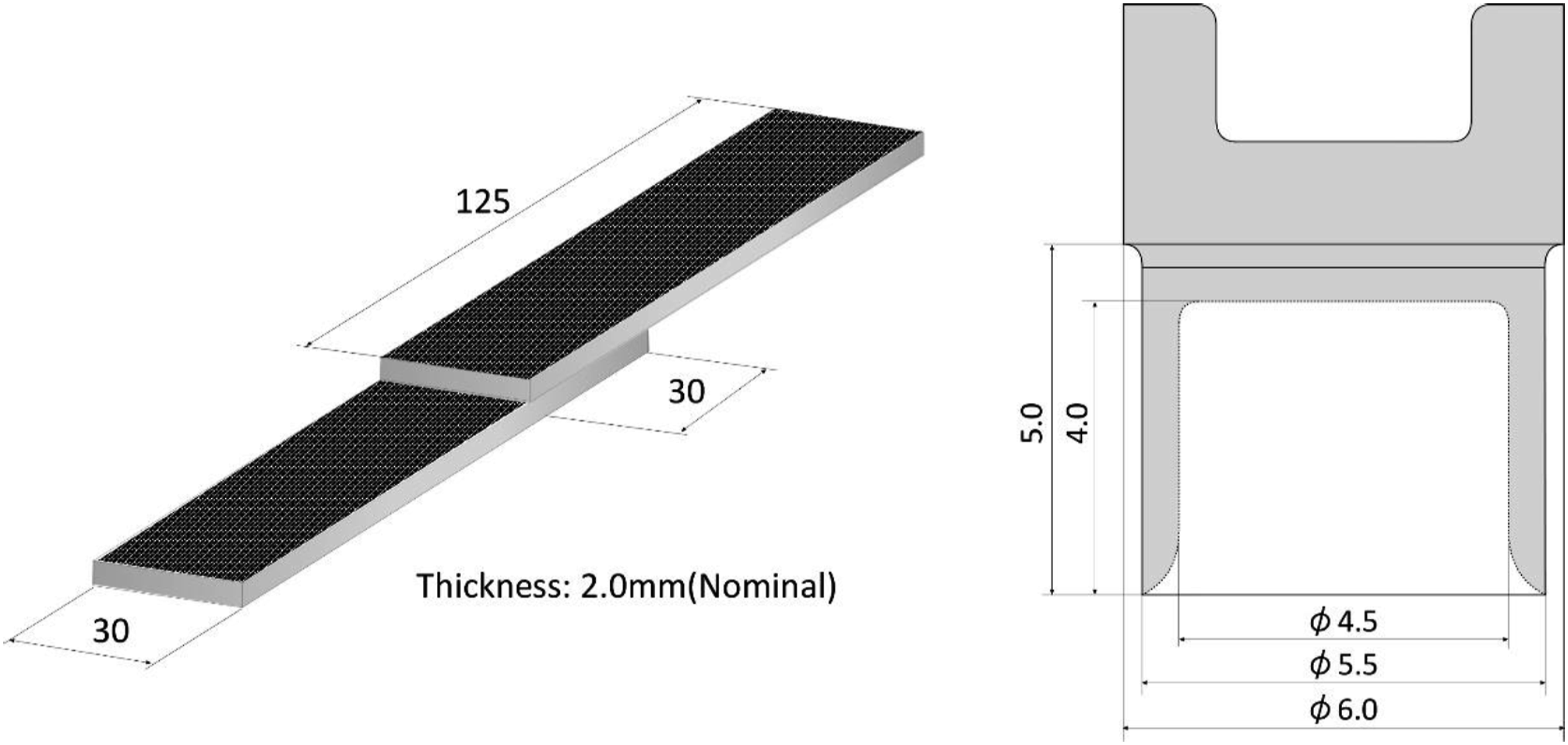
Refill FSSW and combined process
Figure 2(a)–2(c) depict the schematics of the refill FSSW process. The refill FSSW tool comprises a column, cylinder, and clamp; the column is referred to as the probe at the center, the cylinder represents the shoulder around its outer periphery, and the clamp on the outer periphery attaches the material during the welding process. The probe and shoulder move upward and downward independently while rotating in the same direction at identical speeds. Schematic of the refill friction stir spot welding (FSSW) process.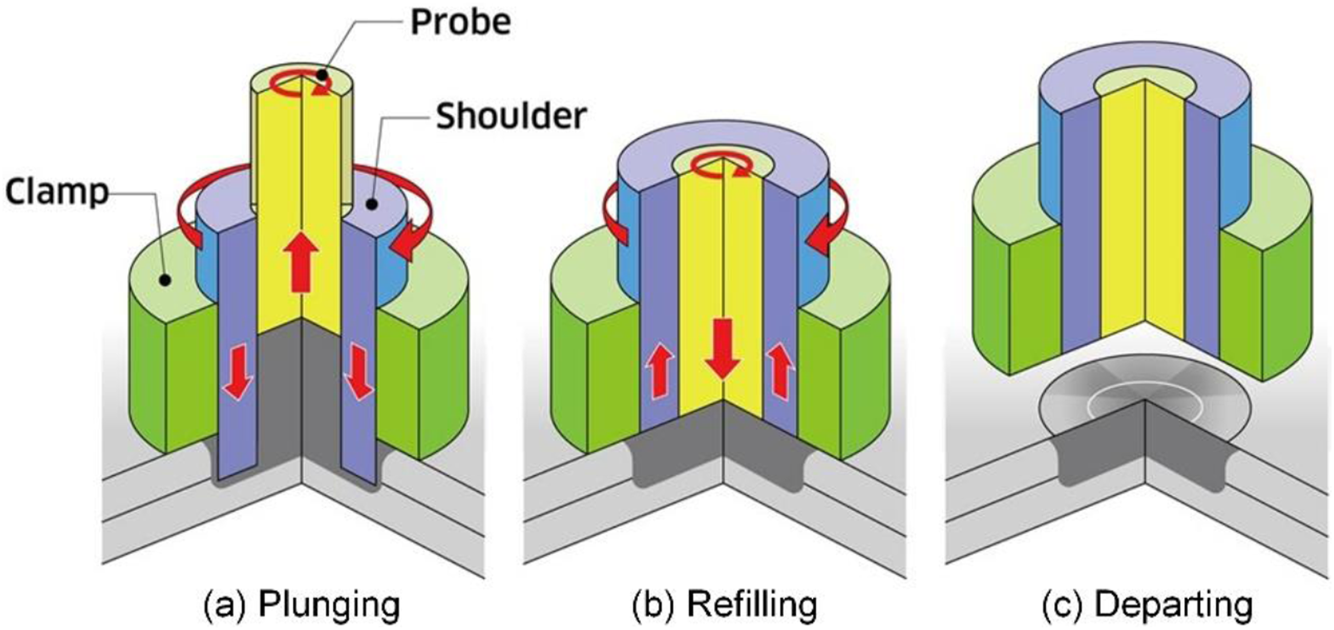
Initially, the shoulder begins to rotate and descend; after touching the surface of the material at the top, the shoulder generates heat caused by friction. After the material is softened, the shoulder begins plunging (Figure 2(a)). Simultaneously, a certain amount of material equal to the shoulder press-in volume moves to the inside of the shoulder. After reaching the preset depth, the shoulder moves upward in the opposite direction and the probe begins to descend and pushes the contained material back into the material (Figure 2(b)). Thereafter, the probe and shoulder depart from the material, completing the bonding (Figure 2(c)).
The entire combined process used in this study is similar to the refill FSSW process, except for the addition of a rivet on the inside of the shoulder; Figure 3 illustrates a schematic of this process. The shoulder moves downward and stirs the material, similar to the normal process in the plunging stage. Subsequently, the shoulder moves upward and the probe moves downward, accompanying the rivet and inserting the stirred material inside the shoulder in the refilling stage. Once the probe reaches a preset position, the shoulder and probe remain stationary while the stirred material cools and solidifies. This section is the point that significantly differs from other metallic materials. Schematic of the combined refill friction stir spot welding (FSSW) and riveting process.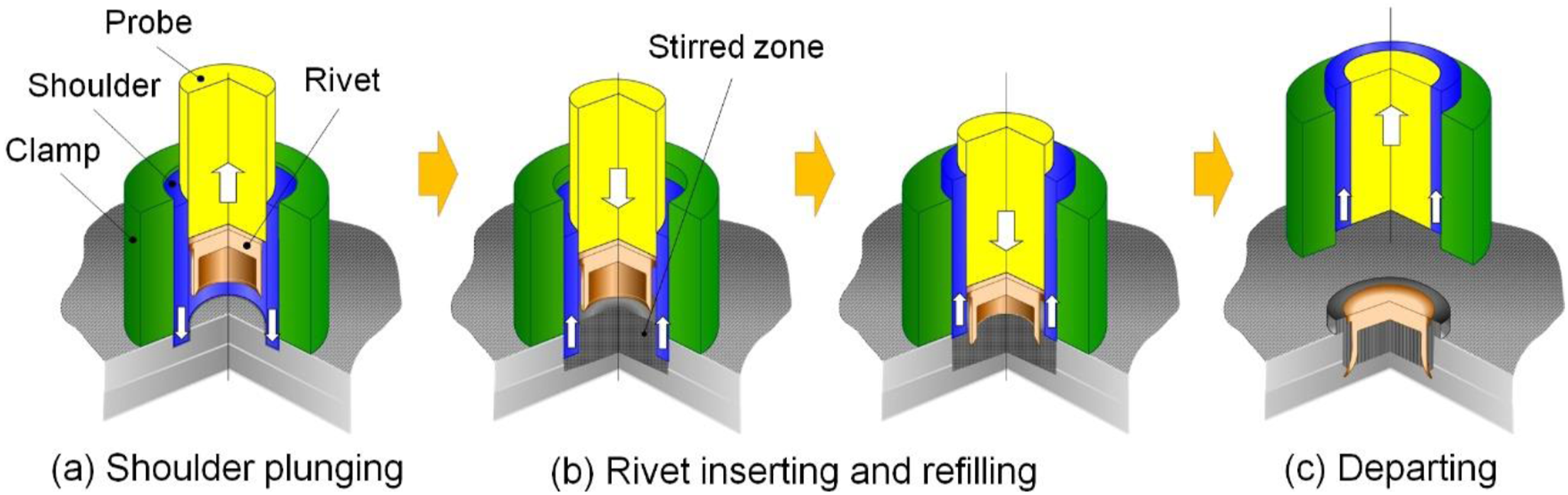
Representative parameters, namely, Z-force and tool displacement, during welding.
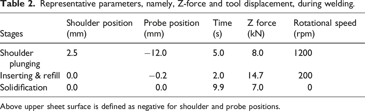
Above upper sheet surface is defined as negative for shoulder and probe positions.
Figure 4 depicts a typical logging profile of the Z-force (load), probe and shoulder displacement (stroke). Before initiating the plunge, the shoulder touches the surface of the upper material and recognizes the zero position on the surface of the test piece. Subsequently, the Z-force is increased to 8 kN, moving to the shoulder plunging stage. As the Z-force is constantly controlled, the shoulder proceeds gradually owing to the softening caused by frictional heat and reaches 2.5 mm lower from the surface. After transitioning to the rivet insertion and refilling stage, the shoulder moves upward. The probe and rivet descend simultaneously with a Z-force of 14.7 kN. Under these conditions, the probe finally reaches 0.2 mm lower from the surface. The shoulder and probe eventually stop rotating, and a Z-force of 7 kN is applied for approximately 10 s to facilitate solidification. Typical logging profile of the Z-force and the displacement of the probe and shoulder during welding.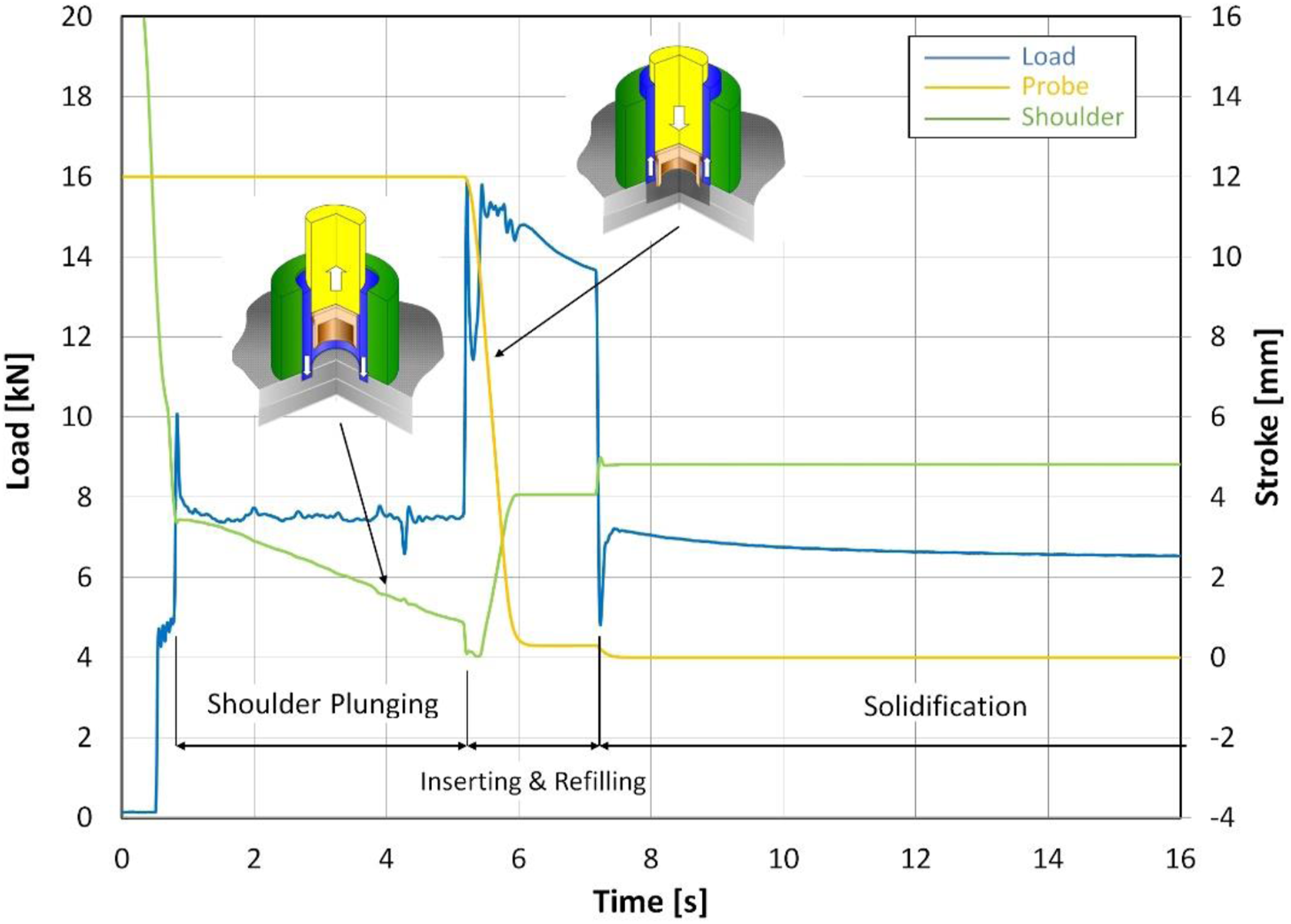
Evaluation
The welded joint was cut and filled with resin to observe the cross-section using an optical microscope to check for the existence of defects and cracks in the stirred zone and rivet. To understand the rivet deformation during the insertion process, the probe was programmed to stop at several preset positions during welding. A lap shear tensile test was performed with the crosshead speed set to 0.17 mm/s, and the fractured part was observed using scanning electron microscopy (SEM).
Results and Discussion
Appearance and Cross-Sections
Figure 5 depicts the appearance of the weld joint. No defects or burrs were observed around the joint, and successful welding was achieved. The stirred material, which corresponded to the volume of the rivet in the base material, was overfilled around the rivet; however, it was solidified using a clamp and shoulder, which served as a mold. The area where the clamp contacted the base material softened and became shiny owing to the transfer of the clamp surface. Although the temperature was not measured during the process, a study reported that the heated temperature during refill FSSW of the CFRP consolidated with PPS was 239°C.
13
Considering that the welding conditions were identical and the melting point of the resin exceeded 280°C, we assumed that no melting occurred during the welding process. Appearance of the joint fabricated by the combined refill friction stir spot welding (FSSW) and riveting process.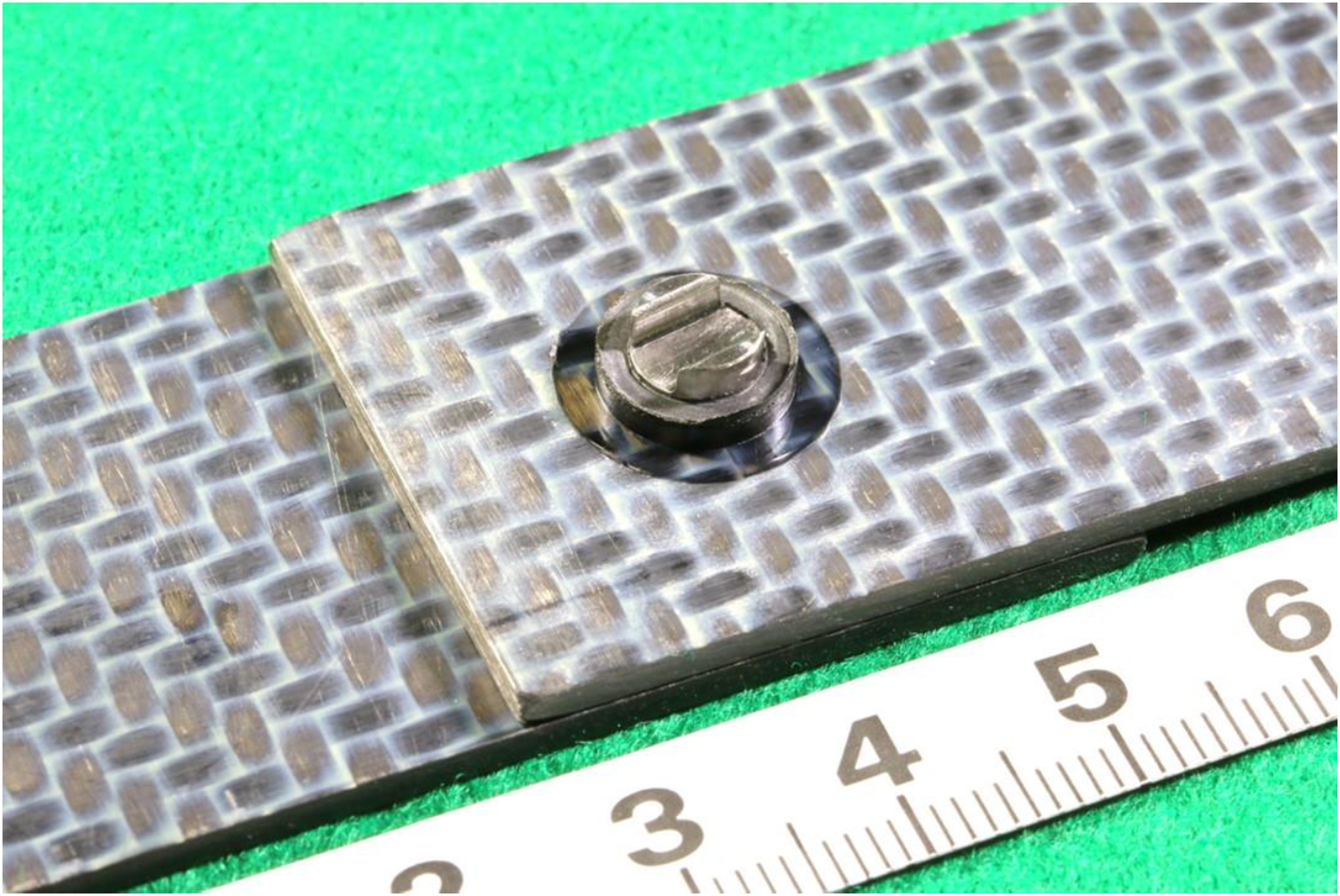
Figure 6(a) depicts a cross-sectional image of the joint. The cylindrical part of the rivet expands and deforms as a trumpet shape after insertion, and the diameter of the rivet tip increases from 5.0 mm to 9.1 mm. (a) Joint fabricated by using the combined process. The rivet tip has expanded in the stirred section and a gap caused by spring-back is confirmed between the rivet and stirred zone. (b) Joint fabricated without stirring. Continuous fibers remain around the rivet indicating no occurrence of the stirring action.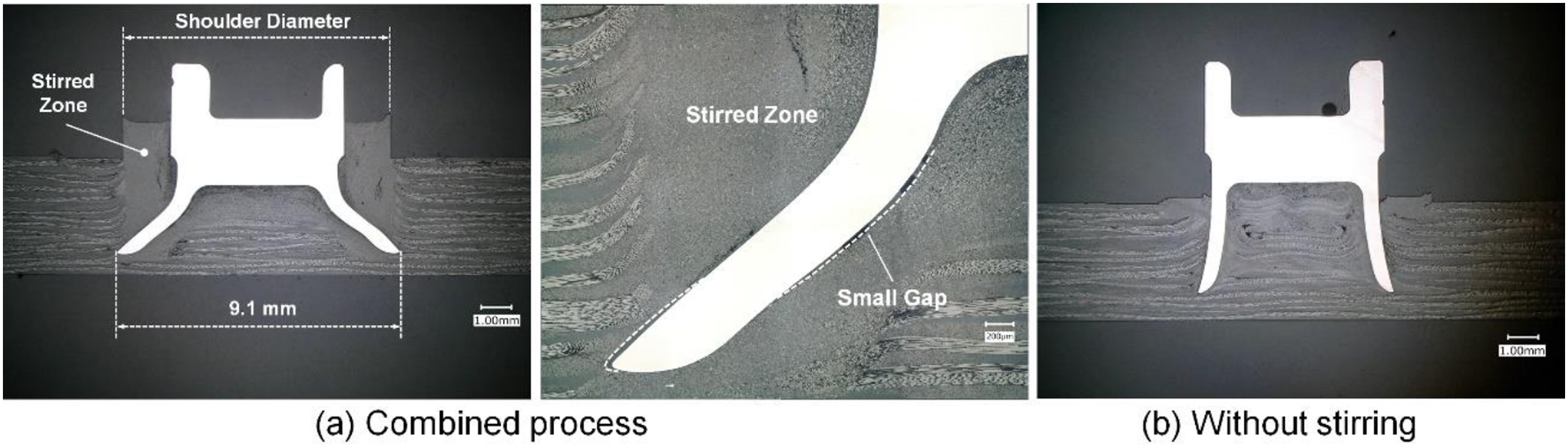
The inside of the cylinder and the surroundings of the rivet were filled with stirred material, and small cavities such as shrinkage nests existed in certain parts of the stirred zone. During refilling, the stirred material protruding above the upper sheet was trapped in the gap created by the clamp and shoulder. This served as the mold, and a smooth surface was formed after welding.
The boundary between the base material and stirred zone was clear. Furthermore, the fibers of the base material moved upward near the stirred zone. By contrast, no continuous fibers were visible in the stirred zone. The cross-section indicated that the insertion depth of the rivet was approximately 4.9 mm, which was slightly deeper than the preset value of the probe position (4.3 mm). The magnified image of the inserted rivet (Figure 6(a)) confirmed the existence of small gaps between the rivet and stirred zone. This gap was attributed to the spring-back of the rivet that occurred during the release of the Z-force. Although the tip of the rivet slightly sank into the base material, no cracks were observed. Moreover, the rivet itself was undamaged and remained crack-free.
Figure 6(b) depicts a cross-sectional photograph of the shoulder without stirring for comparison. The rivet was inserted at a rotation speed of 1200 r/min and Z-force of 10 kN. Although the rivet tip expanded slightly, its diameter remained relatively small. Additionally, continuous fibers remained inside the rivet cylinder, and few stirring actions were performed by the rivet. These results indicate that the formation of the stirred region contributes to a wider expansion of the rivet tip.
Deformation behavior of the rivet
To investigate the behavior of the rivet deformation in the refilling stage, cross-sections with several depths of the insert were obtained by varying the value of probe displacement set in the welding program (conducting “Stop action”); Figure 7 depicts the cross-sections obtained at various displacements. As the rivet was insufficiently inserted, the rivet was not firmly attached to the base material. Therefore, the rivet separated from the base material when the probe moved upward after the refilling stage. Although the rivet appeared to be away from the base material in the cross-sectional phototroph, the position where the rivet existed could be recognized by tracing the marks formed by the rivet in the stirred zone. The mark of the rivet tip in the stirred zone is indicated by a yellow dotted line, and the boundary between the stirred zone and base material is indicated by a white dotted line. Cross-sections obtained by varying the position of the probe tip. The probe tip is (a) 2.0 mm upward, (b) 2.0 mm downward, (c) 2.9 mm downward, and (d) 4.3 mm downward from the material surface to investigate the deformation process of the rivet. Owing to the insufficient depth of the insert, the rivet separates from the base material when the tool departs after welding.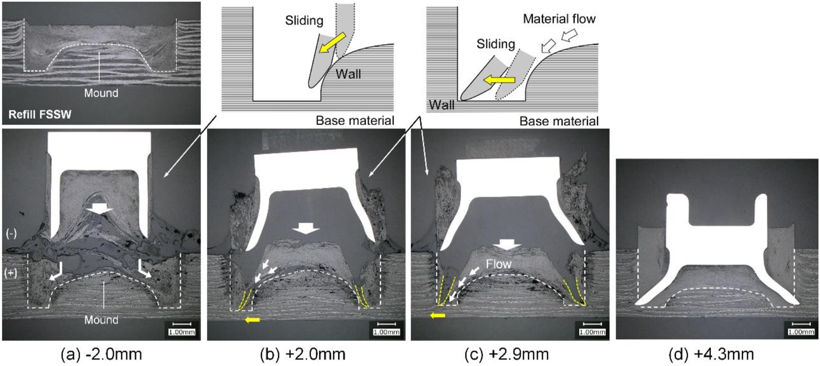
Figure 7(a) depicts the cross-section when the probe tip is located 2 mm above the material surface. The passage area of the shoulder and the stirred zone in the base material are clearly identified by the white dotted line. A mound-shaped protruding zone exists near the center of the base material, where a few continuous fibers remain as the base material. A cross-section obtained by refill FSSW without rivet is also indicated in the figure; the mound-shaped region near the center is also visible. This can be attributed to the use of the cylindrical shoulder, indicating that the formation of this mound is a unique characteristic of the refill FSSW for CFRTP. By increasing the insert depth, the rivet tip expands into a trumpet shape and increases in diameter (Figure 7(b) and 7(c)). The trace lines indicate the two primary reasons that could explain the deformation of the rivet: (i) a wall guiding effect caused by the hard surface of an unstirred base material; (ii) the escaping force generated by the compression flow of the stirred material. According to the first reason, the tip of the rivet contacted the mound region near the center when the insert depth increased (Figure 7(a)). As the diameter of the cylinder was smaller than the outer diameter of the mound region, the contacted tip began to slide along the wall as the rivet proceeded downward, which triggered flaring. As the insert depth increased further, the rivet tip continuously moved and reached the base material surface, which was the bottom surface of the stirred zone (Figure 7(b)). The tip of the rivet slid along the hard surface of the base material acting as the guide and expanded further. Additionally, the stirred material constituted the inside of the cylinder entirely as the insert depth increased, and the volume of the stirred material exceeded that inside the rivet. Moreover, the compression pressure inside the cylinder became higher than that of the outer region of the rivet, and the stirred material flowed outside the rivet; this acted as a driving force to flare the rivet tip (Figure 7(c)). Therefore, both the geometric guide effect and the volumetric material flow from inside the cylinder could enlarge the rivet tip.
Lap shear test
Figure 8 depicts the failure load during the tensile shear test; the results of the riveted joint without stirring and the refill-FSSW joint are both illustrated for comparison. The maximum failure load of the joint fabricated using the combined process was 71% higher than that of the riveted joint without stirring; conversely, the maximum failure load increased by 6% in comparison with the joint obtained by refill FSSW without riveting. Fracture load of the joint produced by the combined process (N = 2) in the tensile shear test, and the results of the refill friction stir spot welding joint (N = 1) and the riveted joint without stirring (N = 1).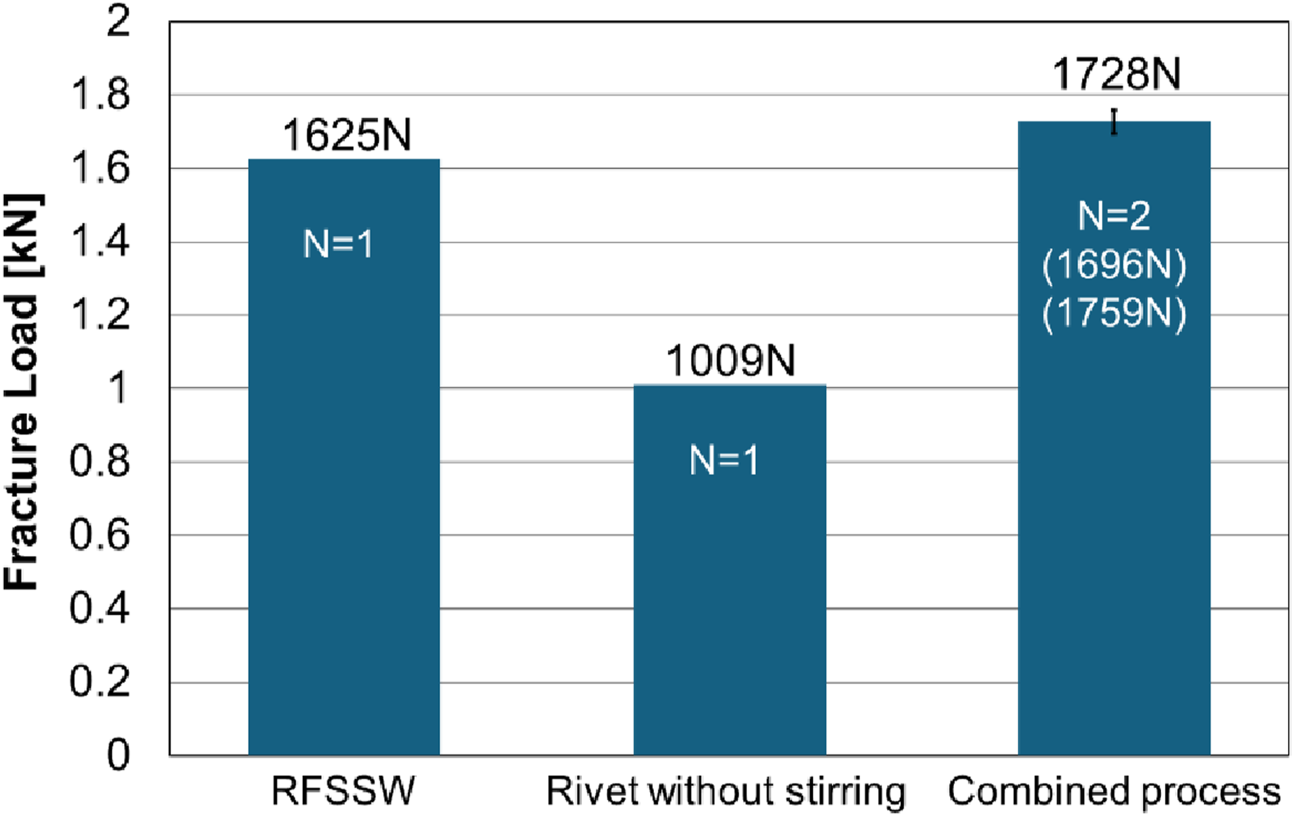
Figure 9 illustrates the load and stroke diagrams of the lap shear joint fabricated via the combined process and refill FSSW without riveting. Certain differences were observed in the profile other than in the maximum load. In the case of refill-FSSW joints, the tensile load increased with the increase in stroke, reaching the peak and eventually fracturing. Conversely, although the joint fabricated by the combined process appeared identical to the refill-FSSW joint in the beginning, the load decreased unexpectedly after exceeding approximately 1 kN. This resulted in a saw-shaped yield point elongation. Subsequently, the load increased again and reached its peak before decreasing gradually. Although the morphology was slightly different in terms of the occurrence of discontinuous elongation after yielding, Schäfer et al.
13
also reported a sudden reduction in the tensile load with respect to the refill-FSSW joints. They reported that no delamination was observed from the test piece, and assumed that the generation of cracks during the tensile test caused the unexpected reduction in load. Load and stroke diagrams of the joints obtained via refill friction stir spot welding (FSSW) and the combined process. Energy consumption until breakage and the cross-section at Point I: yield point elongation; and Point II: after peak load.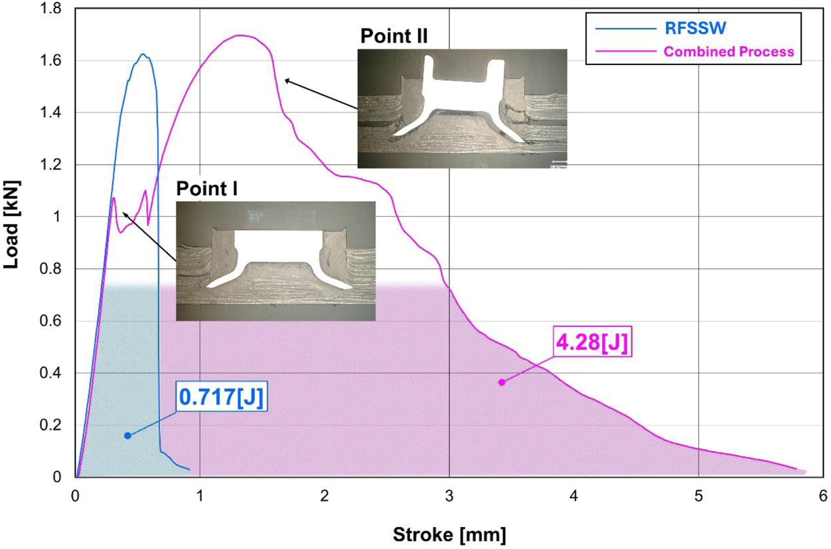
Another difference between the two joints was the total elongation up to breakage. The joint fabricated via the combined process exhibited a long duration up to failure. The energy consumption during this period for the refill-FSSW joint was 0.717 J, whereas the joint obtained via the combined process indicated an energy consumption of 4.28 J. Despite the breakage, the rivet remained in the lower sheet and the final failure occurred at a different place, indicating that the rivet had firmly joined the base material and had withstood the tensile load. The interlocking effect of the rivet contributed to the elongation until breakage.
To clarify the reason for the different behaviors, the tensile test was interrupted at Points I and II (Figure 9) and the cross-sections were analyzed (Figure 10). At Point I, relatively large cracks were generated at the boundary between the stirred zone and base material, as indicated in “Area B″ and “Area C” (Figure 10), where a prime path of tensile load existed. Additionally, small cracks were generated at the boundary between the stirred zone and material in “Area A.” Moreover, owing to the rivet tilting, the tip in “Area B″ was lifted according to the lever principle, inducing the generation of a small crack in the base material. Large cracks were generated at the boundary of the stirred zone and base metal in the path of the load, and small cracks generated by the rivet tilting induced the yield point elongation at Point I (Figure 9). In the cross-section at Point II, multiple cracks were generated in the stirred zone, increasing the inclination of the rivet. No cracks were propagated in “Area D″ in the base material. However, the rivet was slightly pulled in “Area E,” and the tip of the rivet bit the base material causing its delamination. This indicates that the rivet tip can serve as a wedge, and the shape of the tip should be more rounded. Cross-sections obtained at Points I and II in Figure 8 via the stop action in the tensile shear test.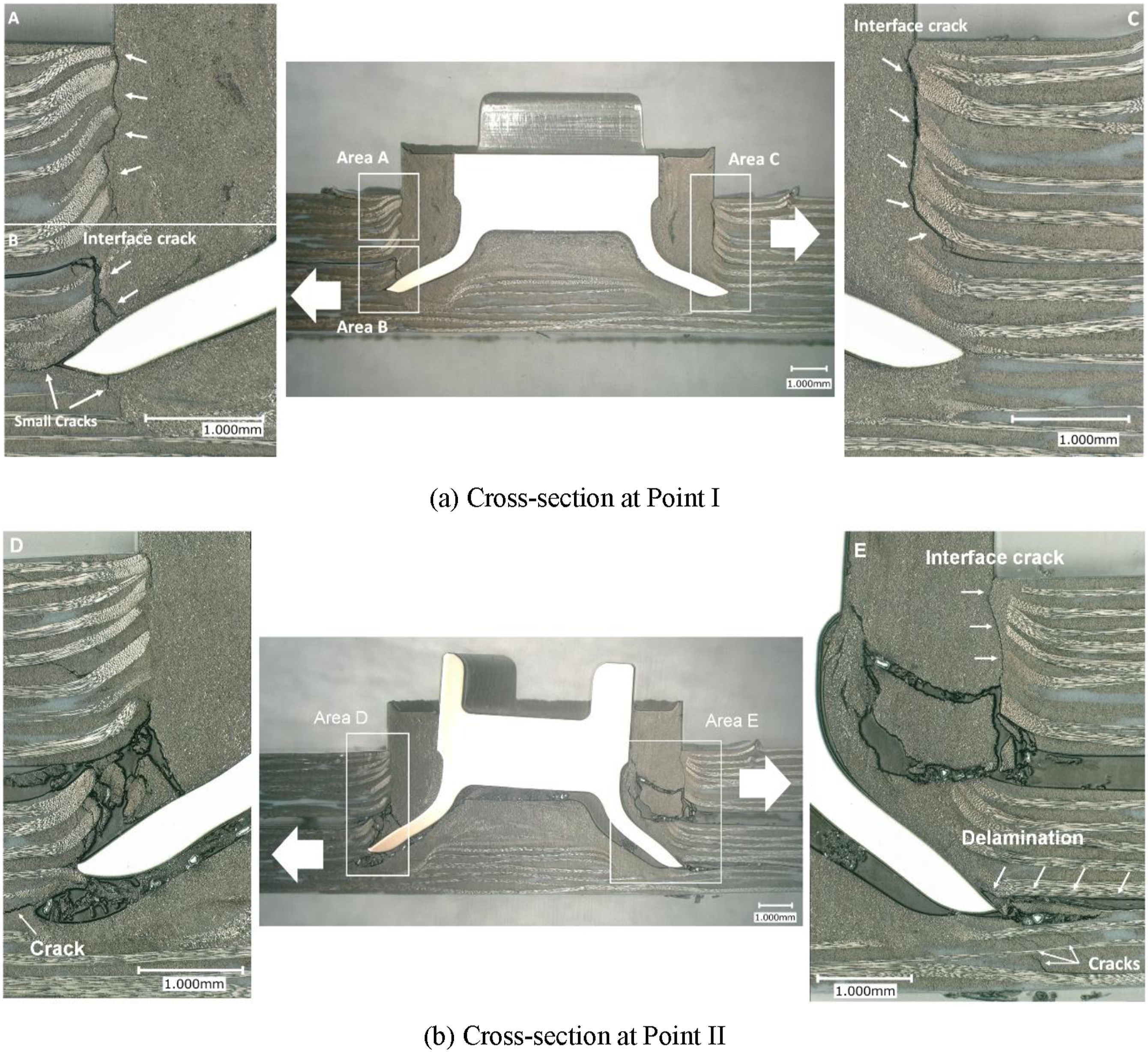
Figure 11 depicts the appearance of the fractured part. Although the rivet remained on the lower sheet, the upper sheet slipped from the rivet, causing the pull-out fracture. This was attributed to the crack propagation within the stirred zone as well as the upward component force induced by the inclination of the rivet, which facilitated the pull-out fracture. Pull-out fractured part of the upper sheet observed from behind and the lower sheet where the rivet remained. The upward force component is generated owing to the rivet inclination.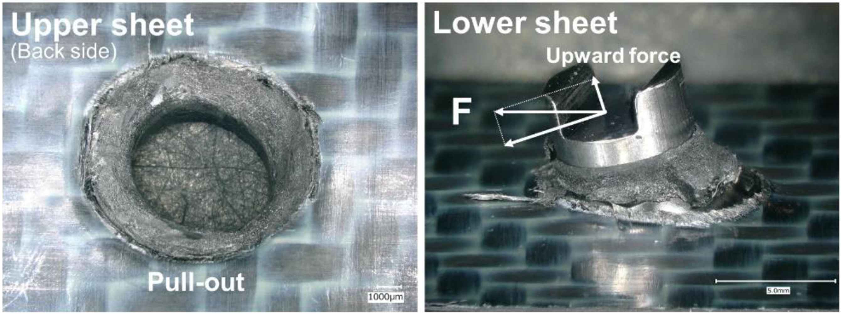
The aforementioned analysis confirms that large cracks are predominantly generated at the boundary between the stirred zone and base metal, and the small cracks generated on the base material, which propagate owing to the tensile load, result in yield point elongation. Subsequently, the load increases again and reaches the peak, with a large displacement up to the breakage owing to the interlocking effect of the rivet. Finally, the dividing of the stirred zone and the increase in the inclination of the rivet causes the final pull-out fracture.
Fracture analysis
We performed SEM to investigate the characteristics of the fractured surfaces. Region A in Figure 12 indicates the SEM image of the crack, generated at the boundary between the stirred zone and base material on the upper sheet. In the stirred zone, short fibers appear to be arranged in a single direction. However, long fibers are arranged on the surface of the base material in an orderly manner toward the surface of the upper sheet. Moreover, broken resin is observed at certain locations, such as protrusions on the fractured surface. Region B in Figure 12 indicates the fractured surface of the stirred zone, wherein numerous short fibers exhibit a unidirectional arrangement. The presence of short fibers in the stirred zone was also confirmed by observing the fractured surface of refill-FSSW joints.13,14 The unidirectional arrangement of short fibers was attributed to the effect of shoulder rotation, which implied that the rotating shoulder cut the fibers into pieces, and the circumferential flow induced a unidirectional fiber arrangement. Scanning electron microscopy (SEM) images of the upper sheet where the pull-out fracture occurs, generating cracks at the boundary between the stirred zone and base material. The morphology of the fibers in the stirred zone differs from that at the boundary between the stirred zone and base material.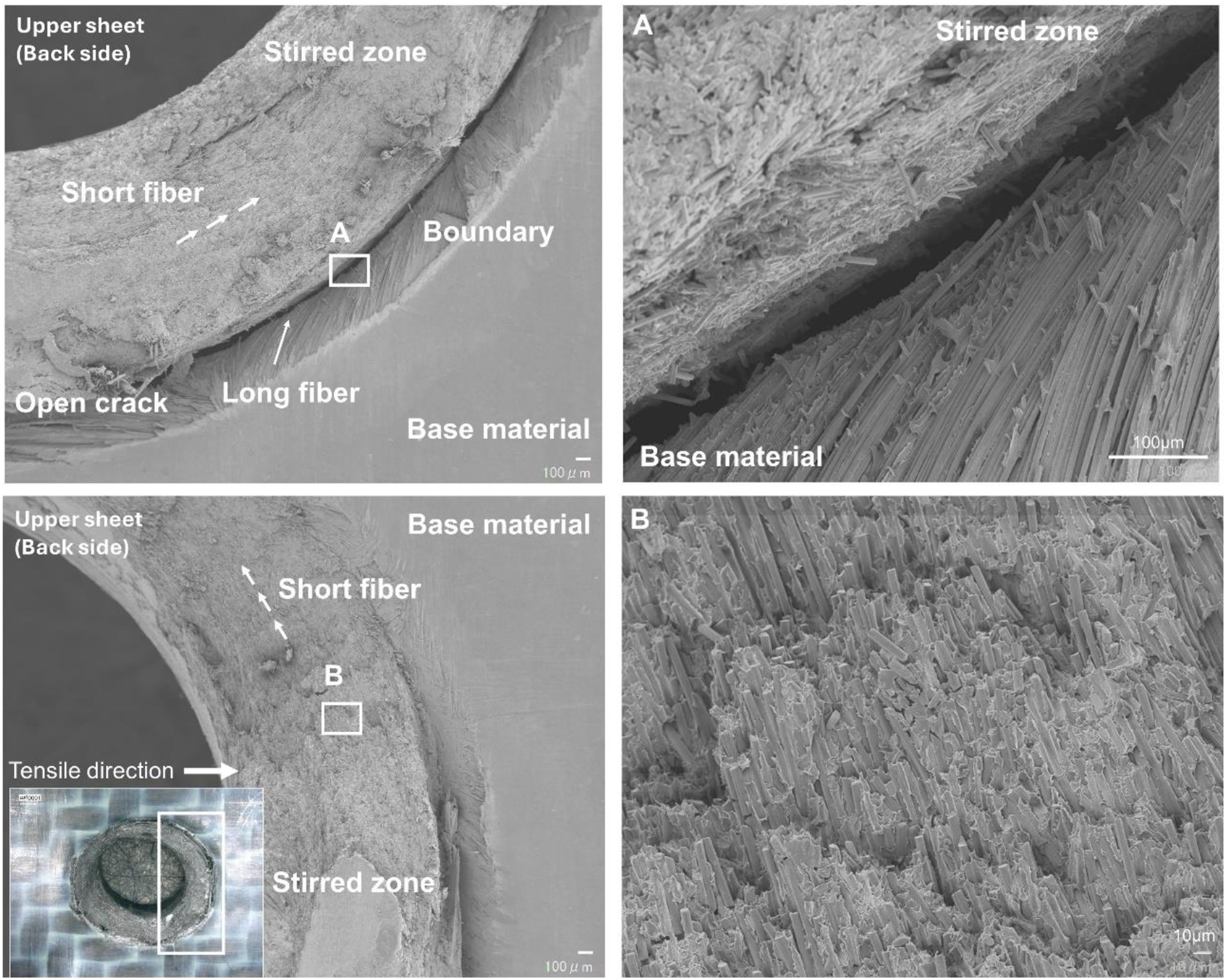
Figure 13 depicts the SEM image of the surface after the removal of the rivet, where the inside of the stirred zone is scratched and exposed. The magnified image indicates that the size of short fibers is approximately 10 μm to 100 μm. These fibers were randomly oriented, contrary to the stirred zone at Region B in Figure 12, where fibers were arranged unidirectionally. These differences can be attributed to the influence of the material during the refilling process. The outside of the rivet was filled with material, which exposed the strong unidirectional flow agitated by the shoulder rotation, whereas the stirring effect inside the rivet was weakened because the flared rivet interrupted the transmission of the rotational flow agitated by the shoulder. This resulted in the random orientation of the fibers. Scanning electron microscopy (SEM) image of the inside of the stirred zone of the lower sheet after removing the rivet, exposing the inside of the stirred zone and the randomly oriented short fibers.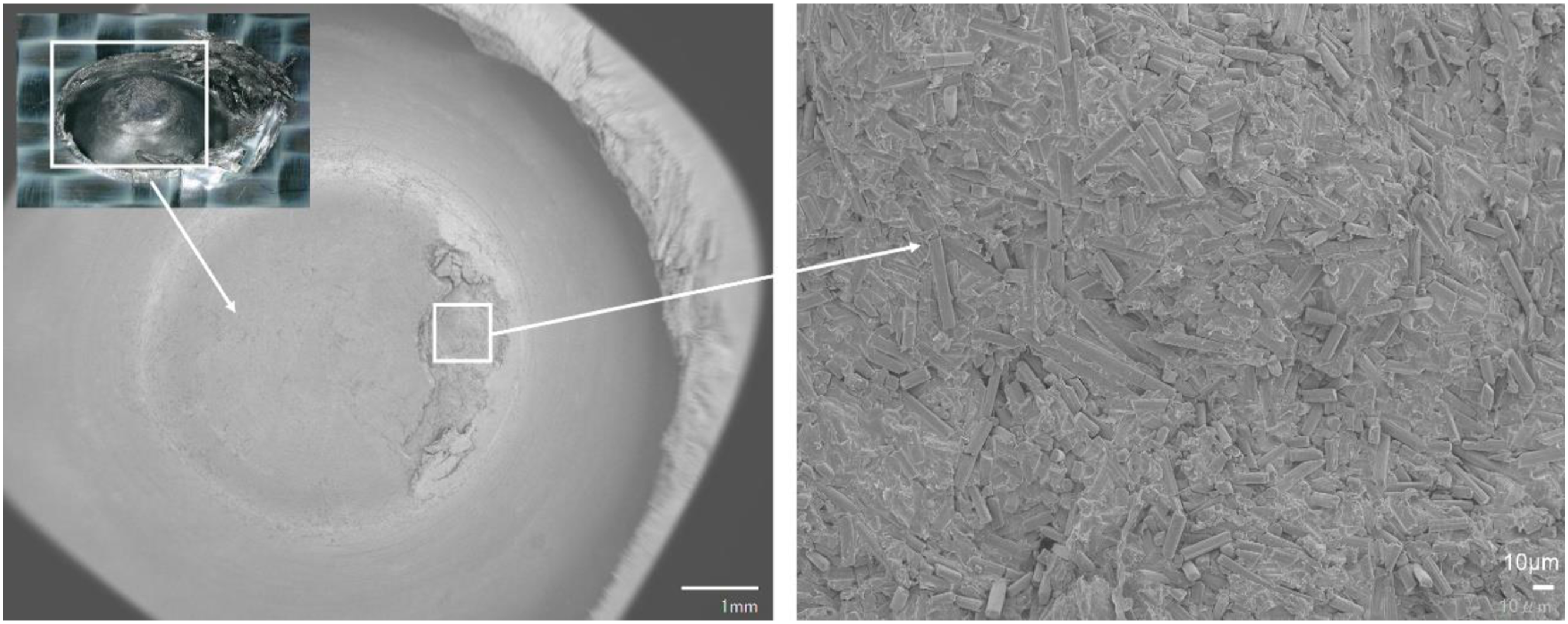
An upward unidirectional orientation of the long fibers was observed in the base material. However, short fibers oriented in the circumferential direction existed in the stirred zone. The mechanical properties in the tensile direction may be discontinuous across the boundary between the stirred zone and base material. The boundary was located transversely along the load path during the tensile test. This may induce and propagate an initial failure at the boundary, causing a discontinuous yielding phenomenon. Further studies on the mechanical properties of composite materials with different fiber lengths and arrangements are required to improve their strength; however, this is beyond the scope of this study and will be considered in future works.
Conclusions
In this study, we investigated the possibility of combining the process of refill FSSW and Ti-6Al-4V riveting for joining thermoplastic composite materials. Our analysis of 2 mm thick CFRTP plate consolidated with PPS confirmed the successful joining process.
Unlike the case where the rivet was inserted without stirring, the tip of the rivet had expanded into a trumpet shape in the proposed combined process. During the rivet insertion, the rivet tip slid along the unstirred base material surface, which served as the guide. Additionally, the stirred material contained inside the rivet flowed out under compression pressure, inducing the expansion.
The joints were subjected to tensile shear tests, wherein the failure load was the highest in the order of riveted joints without stirring (1009 N), refill-FSSW joints (1625 N), and the joints obtained via the combined process (1728 N on average). The total elongation and fracture energy were the highest in the joint fabricated by the combined process (4.28 J) contrary to that of refill-FSSW joint (0.717 J). During the tensile test, a crack occurred and propagated at the interface between the stirred zone and base material as the tensile load increased, resulting in yield point elongation. The load increased further and reached the maximum value, inducing a pull-out breakage in the joint. The tip of the rivet induced delamination in a part of the base material.
SEM observations of the fractured surface revealed that short fibers were predominantly oriented in a single direction in the stirred zone. Conversely, at the boundary between the stirred zone and base material, long fibers on the base metal side were oriented in the upward direction, perpendicular to the fiber orientation in the stirred zone. This anisotropy induced the generation of cracks. In the future, we intend to explore the failure mechanism of bonded surfaces with various fiber characteristics, such as length and orientation.
Footnotes
Declaration of conflicting interests
The author(s) declared no potential conflicts of interest with respect to the research, authorship, and/or publication of this article.
Funding
The author(s) received no financial support for the research, authorship, and/or publication of this article.