
Abstract
Fused-filament fabrication (FFF) is one of the most common 3D printing methods for thermoplastic polymers and composite materials because it is easy to use and is low-cost. The printed polymer parts for industrial applications require desirable mechanical properties. Therefore, in the present research, the process parameters of fused filament fabrication are optimized to enhance the Young’s modulus and bending resistance of polylactic acid/carbon nanotube (PLA/CNT) composite. For this purpose, the response surface method (RSM) and desirability function technique (DFT) are applied to find the optimal values of the effective parameters of CNT content, printing speed and nozzle temperature. The printed samples were examined by using DSC, TGA and SEM analyses. The results of DSC and TGA analyses indicated that the addition of CNT into PLA enhanced the thermal stability of PLA/CNT composite. It was also observed from the optimization results that the Young’s modulus and bending resistance of PLA/CNT composite improved at CNT content of 2.9 wt%, printing speed of 20 mm/s and nozzle temperature of 210°C.
Introduction
Polylactic acid (PLA) is a biocompatible and biodegradable thermoplastic polymer material that has higher mechanical strength than other thermoplastics, and also has good processability. 1 This polymer is widely used in the packaging industry, food industry and various medical applications such as tissue engineering, drug delivery systems, membranes, implants, scaffolds, and sutures.2–4 The main advantages of polylactic acid include biocompatibility, biodegradability, easy processing and high mechanical strength compared to other polymers. 1 According to the mentioned properties, PLA as a matrix material has great potential in the development of nanocomposite. 5 Despite the numerous advantages of PLA, its inherent brittleness and poor thermal stability have restricted its widespread applications.6,7 Therefore, an additive is needed to ensure the stiffness of the PLA matrix. 8 One of the excellent additives that simultaneously improves the mechanical properties of polymers is carbon nanotubes (CNTs).8,9 It is well established that CNTs have good potential for industrial applications because of their unique structure and properties such as excellent mechanical, electrical, and thermal properties. 10 Yang et al. 11 reported that the addition of 6 wt% CNT improved the tensile strength and bending resistance of PLA/CNT by about 64.12% and 29.29%, respectively. Zhou et al. 6 observed that the impact energy, elongation and tensile strength of PLA enhanced by addition of CNTs. They also stated that the thermal stability of PLA/CNTs composite increased than pure PLA. Vidakis et al. 8 found that the mechanical properties of PLA/CNT composite were significantly improved by incorporation of 1 wt% CNTs. Pinto et al.9,12 have also found that the mechanical properties of PLA/CNT composite were improved by incorporation of CNTs. Ristić et al. 13 stated that the addition of CNTs into PLA enhanced both the tensile strength and Young’s modulus of the composite. Lee et al. 14 reported that the Young’s modulus and thermal stability of the ternary PP/PLA/CNT composite improved with the increase of CNT loading. Guo et al. 15 observed that incorporation of CNTs into PLA improved the flammability and thermal properties of the PLA/CNT composite. Rivière et al. 16 reported that with the increase of CNT content up to 5 wt%, the tensile strength of PLA/CNT composite decreased by 26% compared to neat PLA, due to the aggregation of the nanoparticles. Therefore, although the addition of CNTs improves the thermal and mechanical properties of the PLA/CNT composite, but excessive amounts of CNTs lead to the aggregation of the nanoparticles. Therefore, the optimal amount of CNTs should be determined.
In recent years, great attention has been paid to the fabrication of the polymer composites using 3D printers.17–19 One of the simplest and cheapest techniques for fabrication of polymer-based composites is the fused filament fabrication (FFF) method. In the FFF process, the polymer filaments are placed in a heated nozzle to melt. The nozzle extrudes a semi-solid polymer onto a substrate to create the desired 3D part with deposited layers. 20 Usually, the mechanical properties and manufacturing quality of the part produced by the FDM process are poorer than the part produced by conventional manufacturing techniques, which is due to the microstructural anisotropy and the layer-by-layer effect of the forming process. 11 Therefore, it is required to improve the mechanical properties and manufacturing quality of the printed parts by optimizing the process parameters. Many attempts have been made to improve the properties and quality of 3D printed parts. The quality of a printed part depends on a number of parameters which control the performance of the printed part. 21 Anis et al. 22 reported that the dimensional quality of 3D printed PLA parts is significantly affected by nozzle temperature and printing speed. Mohammadimehr et al. 23 stated that a reduction in the layer thickness leads to an increase in the dimensional accuracy and surface quality of the PLA samples, while the printing speed leads to an improvement in the mechanical properties. Chacon et al. 24 concluded that the increase of layer thickness and the decrease of printing speed improved the mechanical properties of PLA. Ahmed et al. 25 observed that the higher tensile strength of CF-PLA/ABS composite was obtained at lower values of printing speed. Magri et al. 26 stated that the tensile properties of both PLA and PLA-CF improved at a nozzle temperature of 230°C. Khosravani et al. 27 reported that the higher Young’s modulus and tensile strength are obtained at printing speed of 20 mm/s, however Kuznetsov et al. 28 reported that highest tensile strength is obtained at printing speed of 25 mm/s and nozzle temperature of 210°C. In another studies, Altan et al. 29 found that the tensile strength of PLA improved at printing speed of 80 mm/s, however Cardoso et al. 30 stated that the lower printing speed improved the tensile strength of PLA. Benwood et al. 31 have also demonstrated that the increase of bed and nozzle temperatures enhanced the impact energy, tensile strength, tensile modulus and bending resistance of PLA. The effect of 3D printing parameters on the mechanical properties of PLA was also examined by Hsueh et al. 32 Wach et al. 33 Liparoti et al. 34 Vanaei et al. 35 Deshwal et al. 36 Veeman et al. 37 Krishnakumar et al. 38 Kumar et al. 39 Akhoundi et al. 40 and Thakur et al. 41
A review of previous works shows that some researchers have tried to produce PLA/CNT composites by compression molding process.8–16 Some researchers have also produced PLA samples by FFF method and investigated their mechanical and thermal properties.22–41 Recently, some researchers have produced PLA/CNT composite by FFF method to investigate its mechanical and thermal properties.8,11 However, in previous studies, researchers have not investigated the effect of different parameters of FFF process on the mechanical and thermal properties of PLA/CNT composites. In addition, optimizing the mechanical properties of the composite has not been performed in previous studies. Therefore, the primary purpose of the present study is to produce the PLA/CNT composite using the fused filament fabrication process. Moreover, the response surface methodology (RSM) is used to investigate the effect of CNT content, nozzle temperature and printing speed on the mechanical properties of the PLA/CNT composite. The desirability function technique (DFT) is also used to determine the optimum values of the FFF parameters for simultaneous enhancing the Young’s modulus and bending resistance of the PLA/CNT composite. Moreover, the thermal properties and microstructure of printed samples are evaluated to justify the variations of the mechanical properties of the printed samples.
Materials and methods
Materials
The polylactic acid (PLA), used in this study, was an industrial grade (PLA 3052D) in the form of a fine powder supplied from Plastika Kritis S.A (Heraklion, Crete, Greece). The molecular weight and Melt Flow Index of PLA were 116,000 g/mol, and 14 g/10 min (ASTM D1238), respectively. The carbon nanotubes (CNTs), supplied from INP Corporation, have a purity of more than 90%. They have a specific surface area of 250–300 m2/g, an average diameter of 9.5 nm and an average length of 1.5 μm.
Fused filament fabrication
The fused filament fabrication (FFF) process was used in this study to fabricate the PLA/CNT composite. To blend polylactic acid (PLA) with carbon nanotubes (CNTs) at different loadings (0, 2, and 4 wt %), a mechanical mixer was applied. Before the filament extrusion, powder compounds of the PLA/CNT composite were dried by placing in an oven at 80°C. A filament extruder (Filabot EX2, USA) was applied to produce filament with a diameter of 1.5 mm. The extrusion of filament was performed at 205°C with a rotational speed of 3.5 r/min. The optimal values of filament extrusion parameters and melt mixing process were chosen by conducting trial experiments and studying previous works.1,8 Before conducting each test, the morphology of filaments was checked visually. The fused filament fabrication (FFF) process was implemented by a 3D printer (Model Wanhao D12-230) to print the composite samples. The FFF process was conducted at different values of printing speed and nozzle temperature. The schematic view of the FFF process was also displayed in Figure 1. FFF 3D printer used in this study.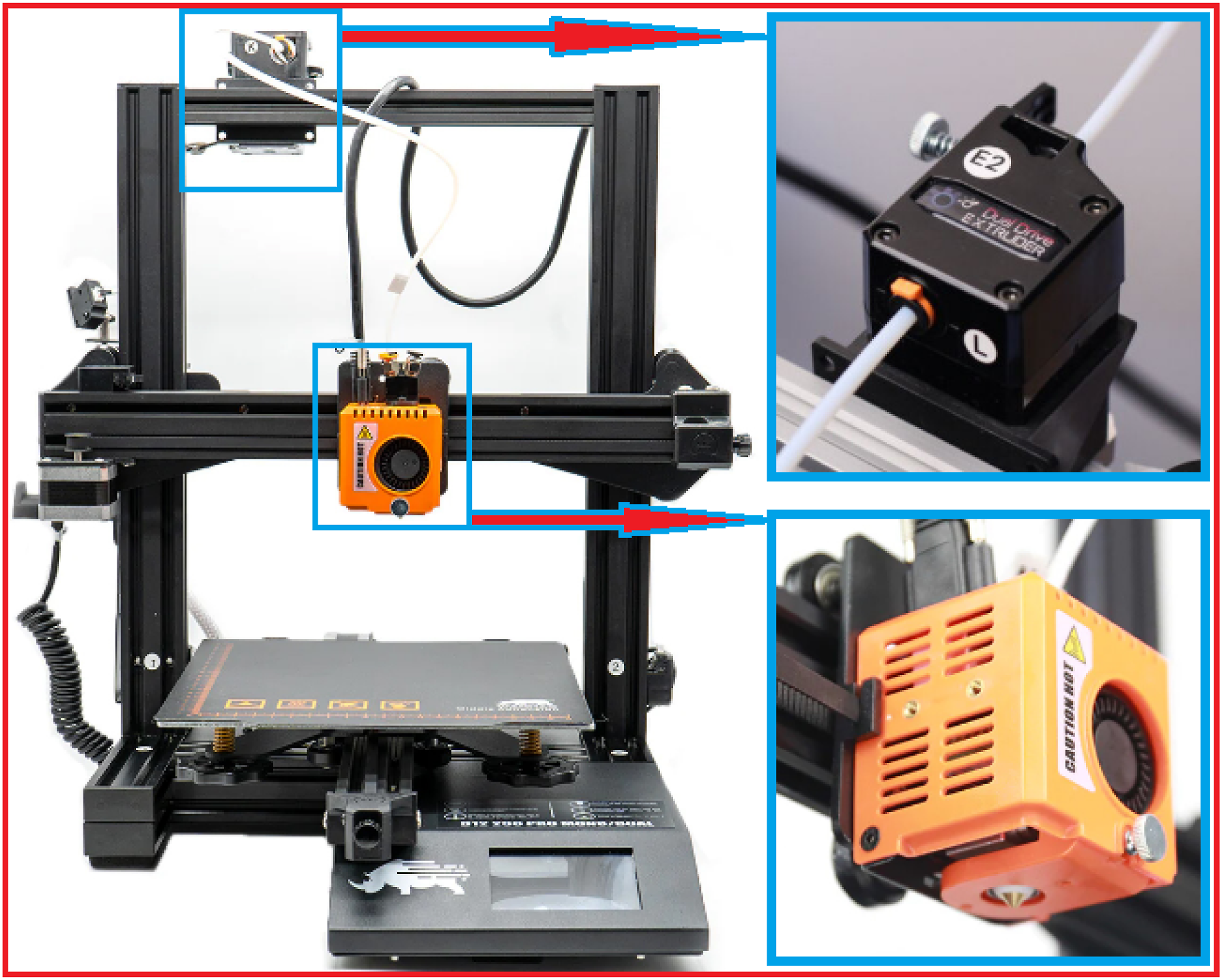
Compression molding process
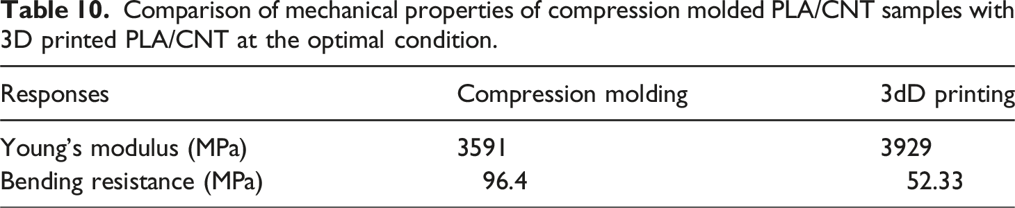
The PLA/CNT composite was also produced by the compression molding process to measure the mechanical properties of the obtained samples. Then, the mechanical properties for compression molded PLA/CNT samples were compared with the mechanical properties for 3D printed PLA/CNT samples. At first, melt compounding process was used to mix 2 wt% CNTs with neat PLA in a co-rotating screw extruder (ZSK 25 P8.2 E WLE) at 200°C for 15 min. Then, the compounded materials were hot-pressed at temperature of 210°C in a Carver Laboratory press (Carver, Inc., Wabash, IN, USA) for 10 min under a pressure of 3.9 MPa to obtain tensile and bending specimens.
Design of experiments
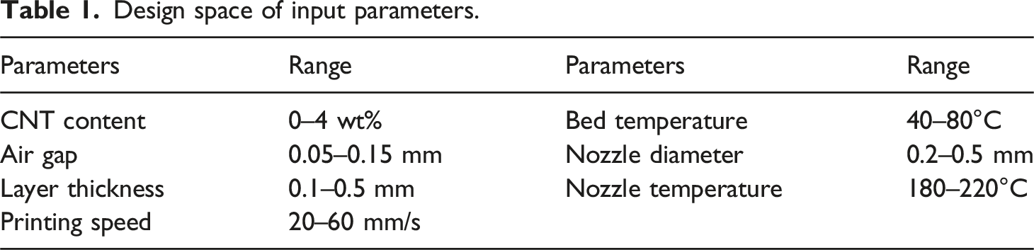
Design space of input parameters.
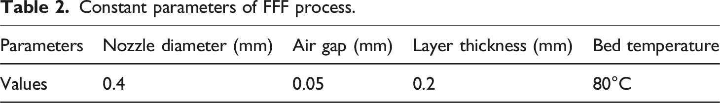
Constant parameters of FFF process.
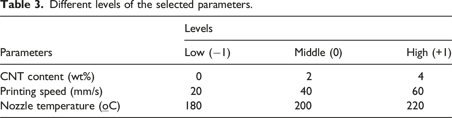
Different levels of the selected parameters.
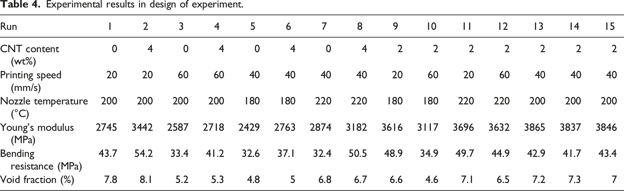
Experimental results in design of experiment.
Mechanical and thermal tests
According to ASTM D-638 standard, the tensile test specimens were printed by the FFF process. Some of the tensile specimens were shown in Figure 2. It can be observed that all the samples broke outside of the gauge length because stress concentration occurred at the fillet radius of the samples, where the geometry changed.42,43 The tensile test was carried out using a Zwick/Roell-Z100 machine with a crosshead speed of 50 mm/min at room temperature. The bending samples were also printed by FFF process based on ASTM D-790. The tensile and bending tests were also performed on the compression molded samples. The printed samples for tensile test.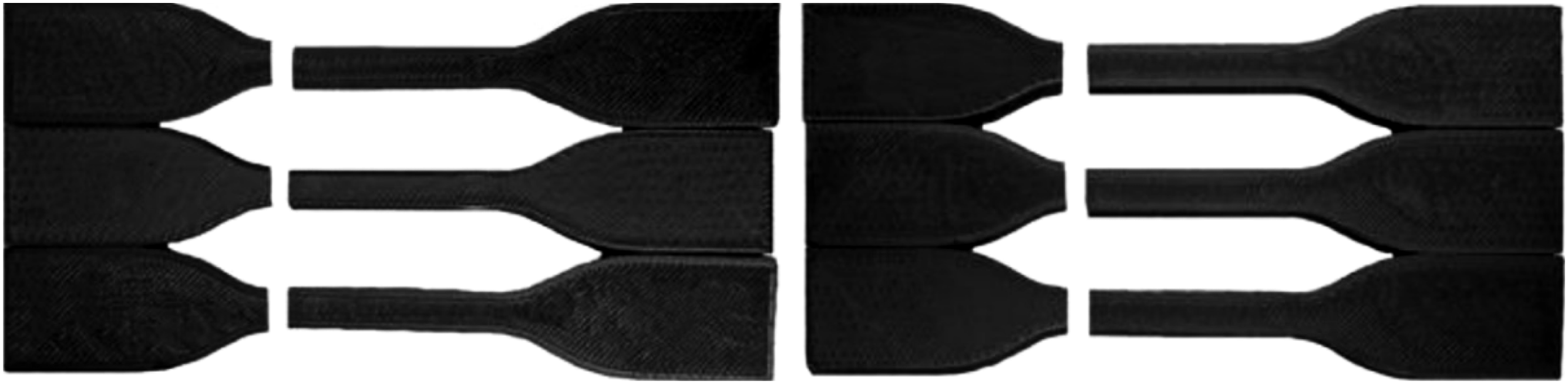
The differential scanning calorimetry (DSC) analysis was carried out (NETZCH 200 F3, Maia) to determine the crystallization temperature (Tc) and melting temperature (Tm) of printed samples. A nitrogen environment was used to perform DSC analysis with a scan rate of 10°C/min at temperatures of 0 to 200°C. It was performed by heating-cooling-heating cycles. The crystallinity (%) of the samples was calculated by the following equation:
Microstructure analysis
The scanning electron microscopy (VEGATESCAN, Czech Republic) was used to examine the fracture surface of tensile specimens. The surface of specimens was coated with a gold layer to take SEM images in a vacuum atmosphere at a voltage of 20 kV. SEM analysis was also used to detect the dispersion of the CNTs inside the PLA matrix. To examine the quality of the FFF samples, the void fraction of samples was measured at different conditions. First, the cross-section of samples was observed by an optical microscopy (Model Olympus CX23), and then the void fraction of samples was measured by ImageJ software.
Results and discussion
Analysis of thermal properties
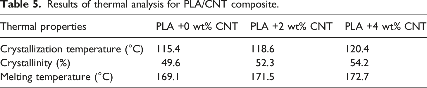
The DSC analysis was performed to investigate the thermal properties of PLA/CNT composite. The results of DSC for PLA/CNT composite were presented in Figure 3. From the results of DSC analysis, the thermal properties of PLA/CNT composite were obtained, as given in Table 5. Table 5 indicates that an increase of CNT content from 0 to 4 wt% was followed by an improvement in the melting and crystallization temperatures of the composites. The addition of CNTs into PLA matrix increases the thermal conductivity of the composite, and consequently improves the heat transfer and thermal stability of the PLA/CNT composite, because the thermal conductivity of CNTs is more than PLA.11,44,45 In addition, DSC results in Table 5 demonstrate that the addition of CNT up to 4 wt% improved the crystallinity percentage of the composite, because CNT nanoparticles acts as nucleation sites for PLA molecules.
46
DSC analysis for cooling and heating cycles. Results of thermal analysis for PLA/CNT composite.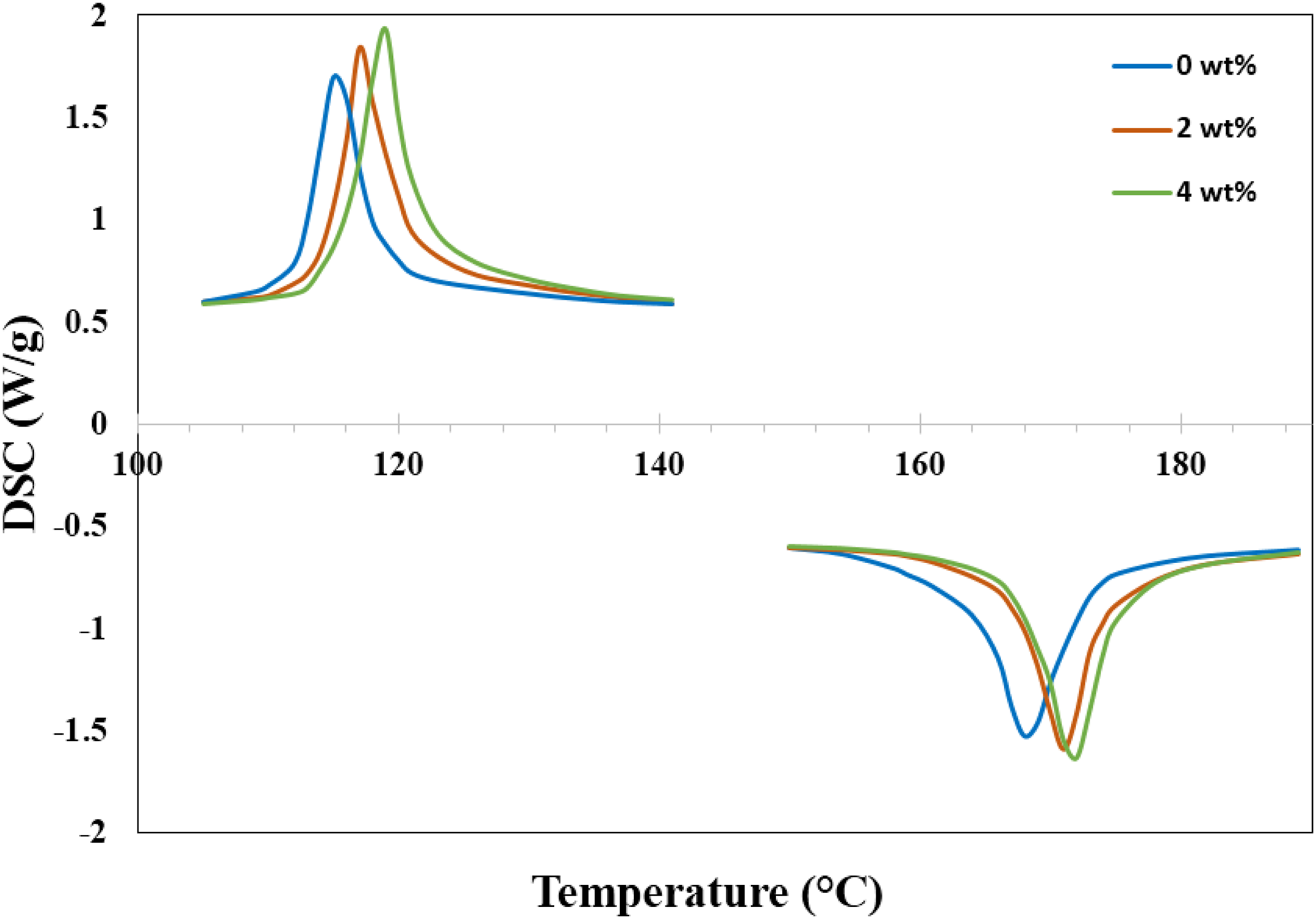
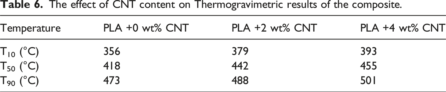
The thermogravimetric analysis was also performed to study the thermal behavior of PLA/CNT composite in temperature range of 0 to 600°C, as shown in Figure 4. It can be observed from Figure 4 that the thermal stability of the composite enhanced with the addition of CNTs in the PLA matrix. PLA matrix undergoes thermal degradation, which begins at 298°C with a continuous mass loss up to 541°C. However, the decomposition temperature of the PLA/CNT composite enhanced up to 311 and 338°C after addition of 2 and 4 wt% CNTs in the PLA matrix. The improvement of the decomposition temperature of PLA/CNT composite is owing to the limitation of the mobility of polymer chains by CNT nanoparticles .47,48 It was also reported by other researchers6,49 that the decomposition temperature of PLA/CNT composite improved by the increase of CNT content. Influence of CNT content on thermogravimetric results.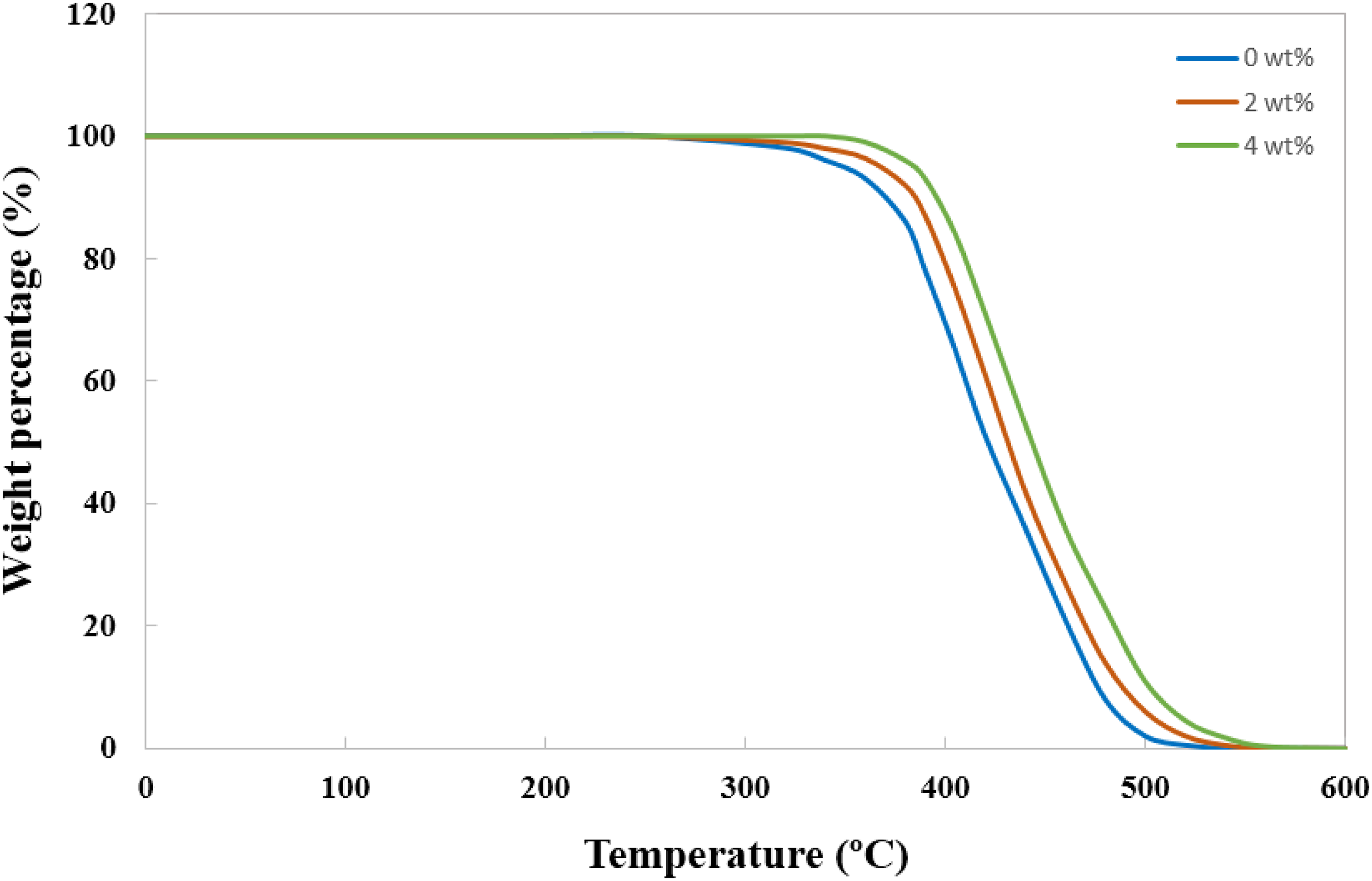
The effect of CNT content on Thermogravimetric results of the composite.
Analysis of microstructure
The interlayer adhesion in the FFF process is very important, because the failure usually occurs at the interface of deposited layers. Thus, the microstructure and mechanical properties of the printed samples are analyzed to investigate the adhesive between the deposited layers. The microstructure of tensile specimens at different percentages of CNT content was shown in Figure 5. It is obvious from Figure 5 that the nanoparticles was well dispersed in the PLA matrix at CNT content of 2 wt% (Figure 5(b)). A strong interfacial interaction can be attained between the CNTs and PLA matrix under this condition, which leads to an improvement in the mechanical properties of the PLA/CNT composite. However, the increase of CNT content up to 4 wt% was accompanied with the aggregation of the nanoparticles (Figure 5(c)). The aggregation of CNTs results in the poor dispersion of the nanoparticles in the PLA matrix, thereby giving rise to deterioration of the mechanical properties of the composite. The influence of CNT content on the fracture surface of composite at: (a) 0, (b) 2, (c) 4 wt%.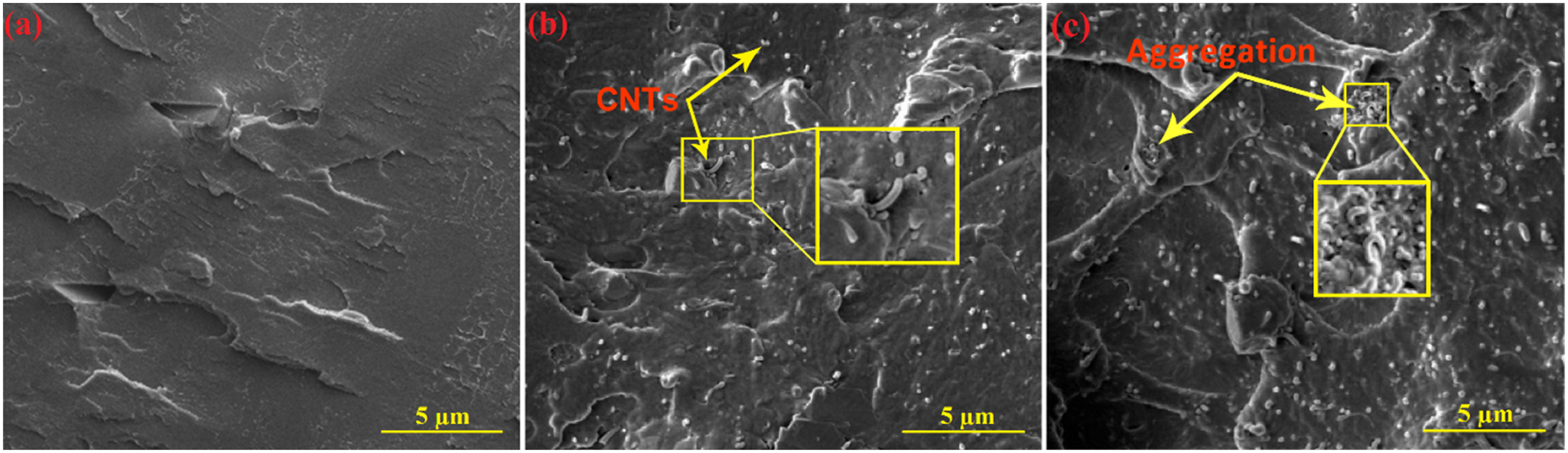
Figure 6 presents the microstructure of the PLA/CNT composites printed at different printing speeds. It is apparent from Figure 6(a) that a good bonding was formed between the filament layers at the low level of printing speed (20 mm/s) due to higher heat input. In fact, when the filament is printed at lower speeds, it remains in contact with the heated nozzle for a longer period of time, which led to a rise in the filament temperature. However, an increase in the printing speed from 20 to 30 mm/s increased the repeated thermal cycles at the previous layers in lesser time, which leads to the formation of interlayer cracks
25
and consequently weakens the bonding strength (Figure 6(b)). Therefore, the presence of defects was declared in the sample printed at a speed of 30 mm/s. According to Figure 6(c), a rise in the printing speed up to 40 mm/s increased the presence of cracks and cavities in the microstructure of the composite due to the decrease of the cooling time and consequently the reduction of the adhesion between filament layers. The fracture surface of the composites at printing speeds of (a) 20, (b) 30 and (c) 40 mm/s.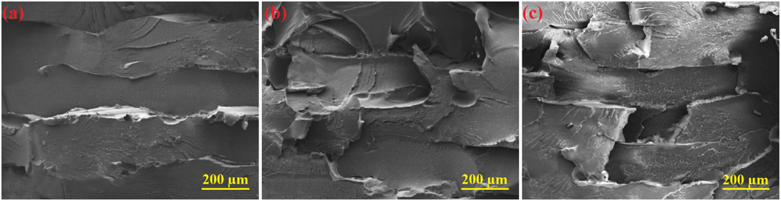
The impact of nozzle temperature on the microstructure of tensile samples was displayed in Figure 7. It can be seen from Figure 7(a) that the adhesion between the filament layers is low at the nozzle temperature of 180°C, because the viscosity of the polymer is high. In the other words, the high viscosity of the filament led to the poor adhesion of the filament layers, which resulted in the formation of cracks and cavities in the microstructure. In fact, when the viscosity of printed filament is high, materials are not fluid enough to be effectively deposited and thus can reduce the adhesion by inhibiting polymer chain interpenetration between adjacent filaments due to the hindering filler.50,51 Figure 7(b) shows that a rise in the nozzle temperature from 180 to 200°C improved the adhesion between the layers owing to the good viscosity of the printed filament. Therefore, the crack and cavity were not detected on the surface of the sample printed at 200°C. However, it can be observed from Figure 7(c) that the increase of nozzle temperature up to 220°C decreased the adhesion bonding between the filaments, which led to an increase in the existence of cracks in the microstructure. The reduction of adhesion between layers may be because the fluidity of the extruded material is very high, which leads to a decrease in the surface quality of the material and the formation of cracks between the layers.52–54 Another reason for reducing adhesion between layers may be the thermal deterioration of PLA materials due to the high temperature of the nozzle.
52
In fact, when the nozzle temperature is too high (220°C), the extruded PLA material is almost liquid or even partially thermally degraded.52–54 The fracture surface of the composites at nozzle temperatures of (a) 180, (b) 200 and (c) 220°C.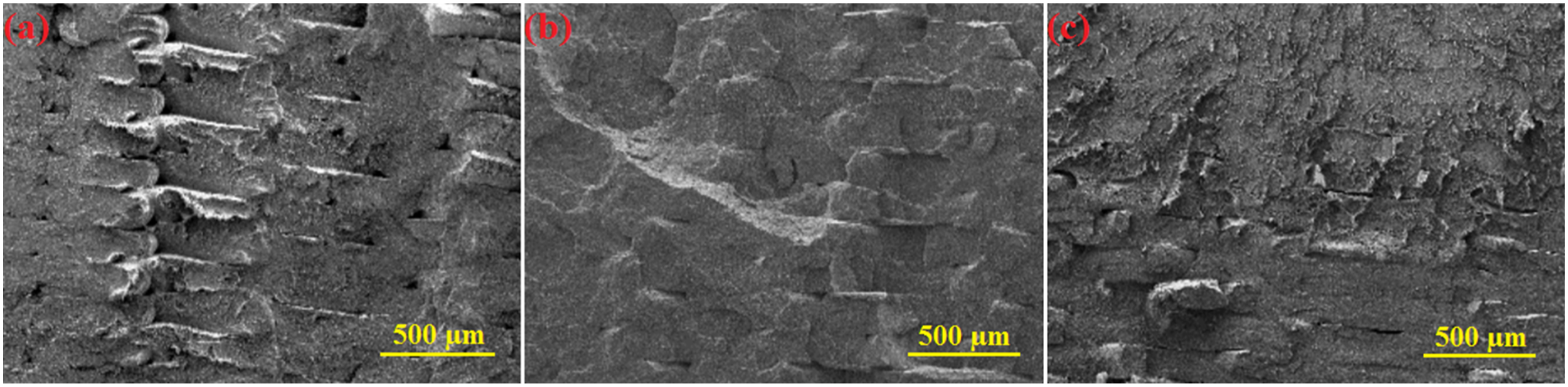
The quality of the 3D printed samples was analyzed by investigating the void fraction of samples at different values of parameters. Figure 8 indicates the void fraction of samples at different conditions. It can be observed from Figure 8 that the effect of CNT content on the void fraction is small, however the lower void fraction was obtained at 2 wt% CNT. The increase of void fraction at CNT content of 4 wt% may be due to the aggregation of nanoparticles. The void fraction of samples at different values of parameters.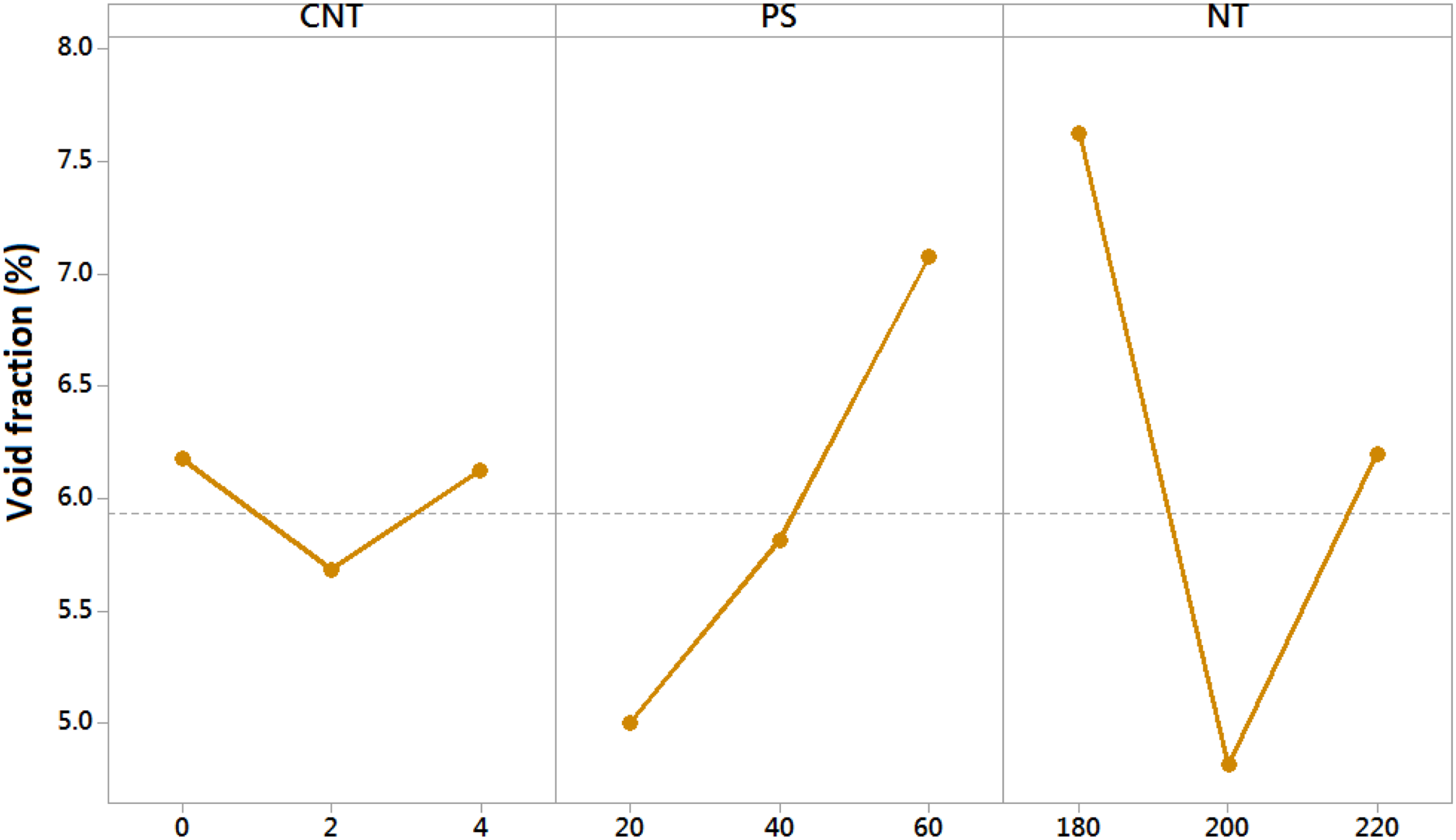
Moreover, the quality of printed samples reduced with the increase of printing speed due to the increase of the void fraction. It can be also observed from Figure 8 that the lower void fraction was obtained at nozzle temperature of 200°C. The increase of the void fraction at nozzle temperature of 220°C can be due to the reduction of adhesion between layers, because the fluidity of the extruded material is very high at 220°C.
Analysis of young’s modulus and bending resistance
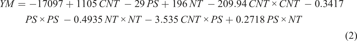

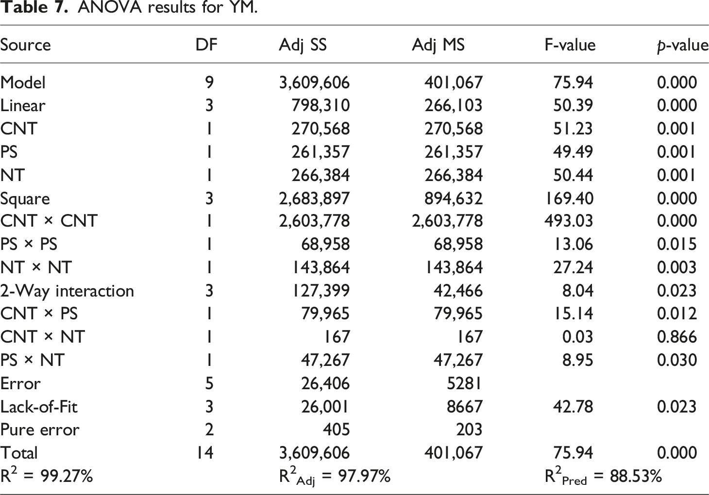
ANOVA results for YM.
ANOVA results for BR.
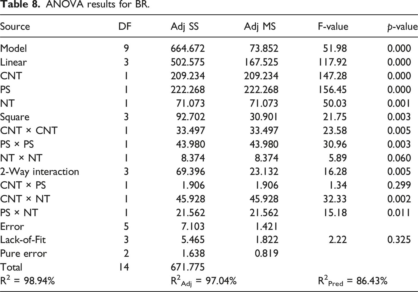
In order to verify the adequacy of developed regression models, the variable of R2, R2Adj and R2Pred were applied. The predictive ability of a regression model increases as the values of R2, R2Adj and R2Pred approach 100%. As can be seen from Tables 7 and 8, the values of R2, R2Adj and R2Pred for YM and BR are close to 100%, indicating that the developed models are capable of predicting the YM and BR.
The impact of CNT content, printing speed and nozzle temperature on the Young’s modulus (YM) and bending resistance (BR) of the PLA/CNT composite was shown in Figure 9. According to Figure 9, the highest Young’s modulus of the PLA/CNT composite was attained at the CNT content of 2 wt% (Figure 9(a)), but the highest bending resistance of the composite was observed at a CNT content of 4 wt% (Figure 9(b)). The variation of the Young’s modulus and bending resistance of the PLA/CNT composite can be explained based on SEM image in Figure 5. The enhancement of the Young’s modulus at CNT content of 2 wt% is due to the fine distribution of the CNTs and thus the strong interfacial interaction between the nanoparticles and PLA polymer. Nevertheless, the aggregation of the nanoparticles at CNT content of 4 wt% led to a reduction in the Young’s modulus of PLA/CNT composite (Figure 5(c)). However, bending resistance of the composite was improved at CNT content of 4 wt%, because the CNT nanoparticles improved the resistance of the composite against bending force. Similar results were observed in.6,11,55,56 Figure 9 also indicates that an increase in the printing speed from 20 to 60 mm/s resulted in a reduction in the Young’s modulus and bending resistance of the composite by about 11.5 and 21.8%, respectively. The enhancement of the Young’s modulus and bending resistance at printing speed of 20 mm/s is because of the formation of the good adhesion bonding between filament layers and consequently the reduction of cracks and cavities in the microstructure (Figure 6(a)). However, the increase of printing speed up to 60 mm/s decreased the bonding strength between layers, which resulted in the formation of defects in the microstructure and thus the reduction of the Young’s modulus and bending resistance of PLA/CNT composite (Figure 6(c)). The decrease of the Young’s modulus and bending resistance of PLA at higher printing speed was also reported in.29,30,57 The effect of process parameters on (a) Young’s modulus, (b) bending resistance.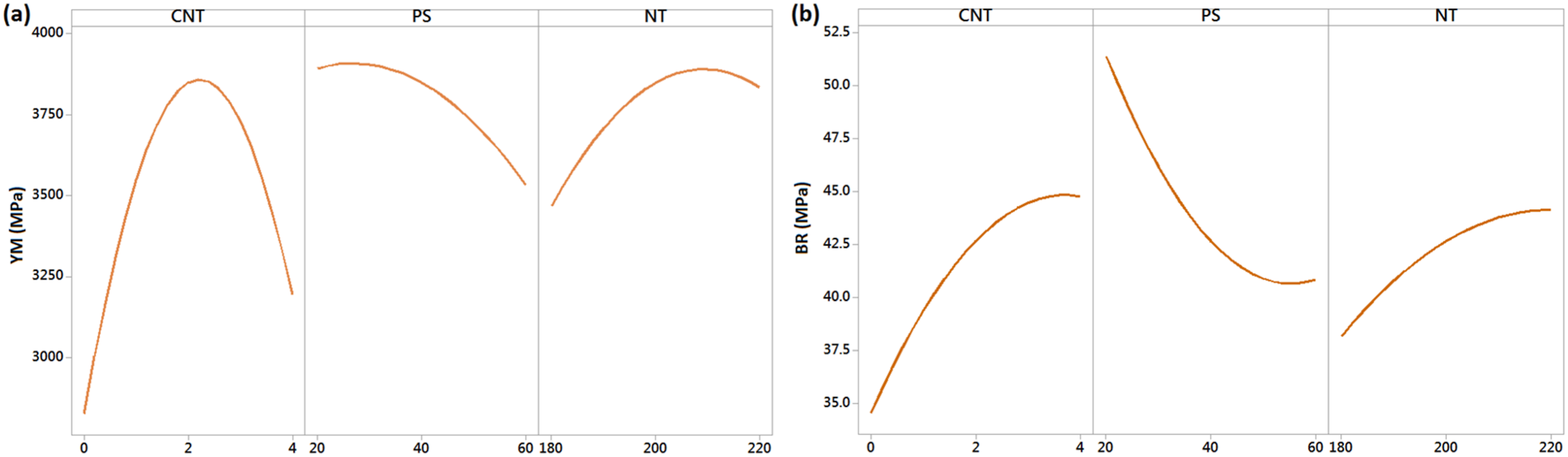
It is also obvious from Figure 9 that an increase in the nozzle temperature from 180 to 200°C was associated with an improvement in the Young’s modulus and bending resistance by about 12.2 and 8.9%, respectively. However, an increase of nozzle temperature from 200 to 220°C decreased the Young’s modulus by 1.8% and improved the bending resistance 3.2%. According to SEM image in Figure 7(b), the higher values of the Young’s modulus and bending resistance at nozzle temperature of 200°C are due to the lower viscosity of the filament and consequently the higher adhesion of the filament layers. The strong adhesion of the filament layers at nozzle temperature of 200°C decreases the formation of cracks and cavities (Figure 7(b)), giving rise to an improvement in the Young’s modulus and bending resistance of the composite. In addition, based on SEM image in Figure 7(a), the deterioration of the Young’s modulus and bending resistance at the nozzle temperature of 180°C can be due to the poor adhesion of the filament layers and thus formation of defects in the microstructure. It worth mentioning that when the temperature between deposited layers is insufficient, it can hinder molecular chain fusion, which leads to formation of a weak interlayer bonding. 58 The obtained results are consistent with those reported in.28,33,35,59,60
The concurrent effect of the parameters on the Young’s modulus and bending resistance was studied by considering the significant interaction in the ANOVA tables. Figure 10(a) and (b) display the interaction effect of CNT × PS and PS × NT on the Young’s modulus, and Figure 10(c) and (d) display the interaction effect of CNT × NT and PS × NT on the bending resistance. From Figure 10(a), it can be observed that when CNT content is 0 wt%, the increase of printing speed has a trivial effect on the Young’s modulus, but when CNT content is 4 wt%, the increase of printing speed decreased the Young’s modulus, because increasing the printing speed reduces the heat input to the polymer and some of the heat is absorbed by CNT nanoparticles. However, the greatest Young’s modulus of the composite was achieved at CNT content of 2 wt% and printing speed of 20 mm/s. The interaction effect of parameters on (a, b) Young’s modulus, (c, d) bending resistance.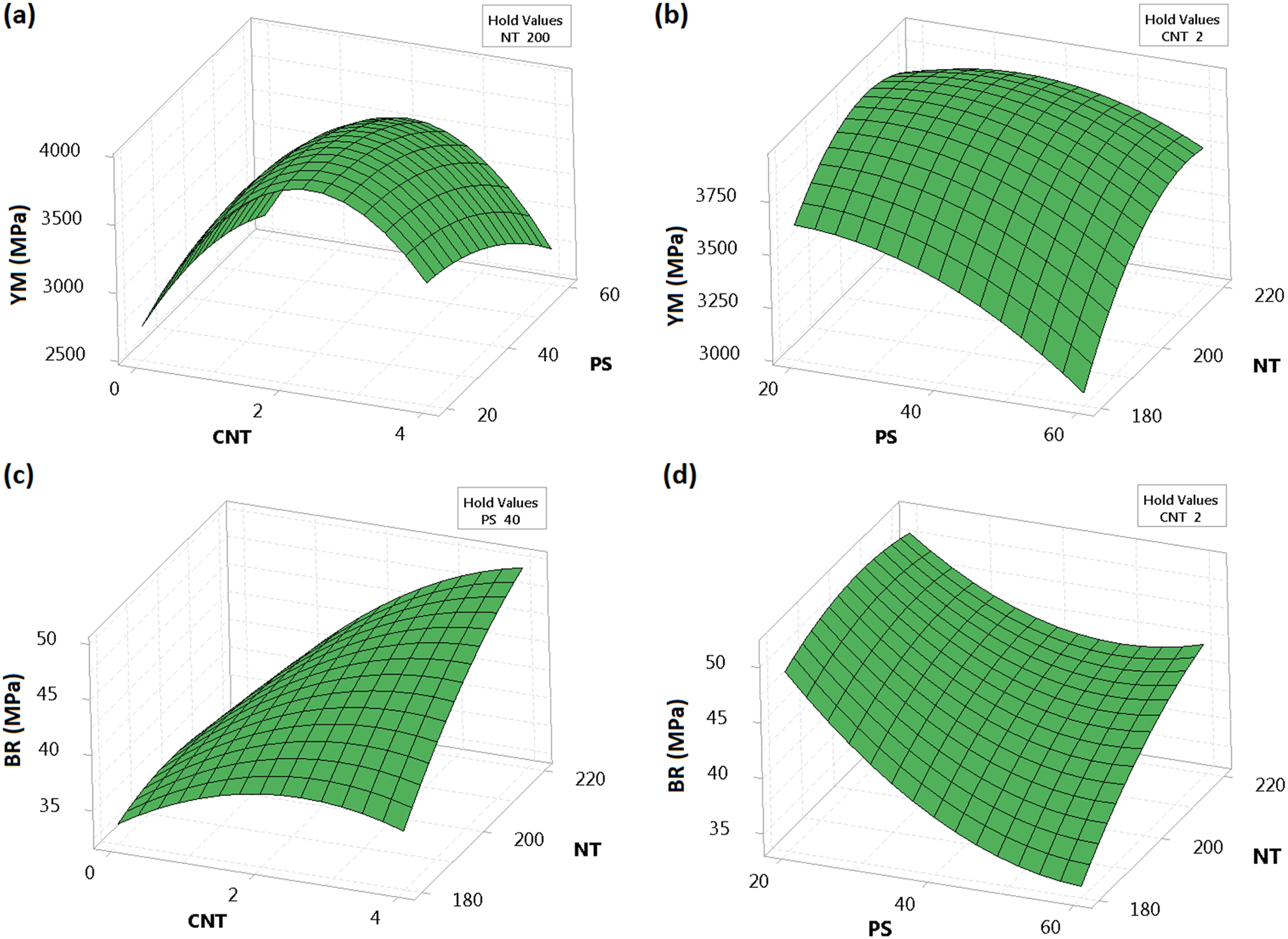
Figure 10(b) indicates that when printing speed is 20 mm/s, the increase of nozzle temperature slightly improved the Young’s modulus, but when printing speed is 60 mm/s, the increase of nozzle temperature strongly improved the Young’s modulus. However, the higher Young’s modulus of the composite was obtained at printing speed of 20 mm/s and the nozzle temperature of 220°C. According to Figure 10(c), for CNT content of 0 wt%, the bending resistance of the composite slightly reduced with the increase of nozzle temperature, while for CNT content of 4 wt%, the bending resistance of the composite considerably enhanced with the increase of nozzle temperature. The enhancement of bending resistance of the composite at CNT content of 4 wt% and nozzle temperature of 220°C can be due to the fact that some of the heat input was absorbed by CNTs and prevented the thermal degradation of the composite. Figure 10(d) represents that as printing speed is 20 mm/s, the increase of nozzle temperature slightly enhanced the bending resistance, but as printing speed is 60 mm/s, the increase of nozzle temperature considerably enhanced the bending resistance.
The desirability function technique was employed to concurrently enhance the Young’s modulus and bending resistance of the PLA/CNT composite. According to this technique, the output responses of Young’s modulus and bending resistance are first transformed to the individual desirability function (d). The geometric mean of the individual desirability functions is then attained to estimate the combined desirability function (D). Eventually, the optimal condition of the parameters is identified by maximizing the combined desirability functions. The desirability function can have a value between zero and one. The number one is the ideal value of the desirability function. Different objectives can be considered to calculate the individual desirability function for each response: 1- higher is better, 2- lower is better, 3- a certain value is better.20,61,62 The objective of this paper is to obtain higher values of the Young’s modulus and bending resistance of the PLA/CNT composite, therefore for estimating the individual desirability function, the first objective is considered. For the objective of “higher is better” the following equation can be calculated to obtain the individual desirability function (d
i
): The results of optimization of parameters by desirability function method.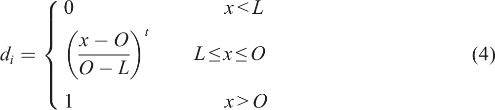

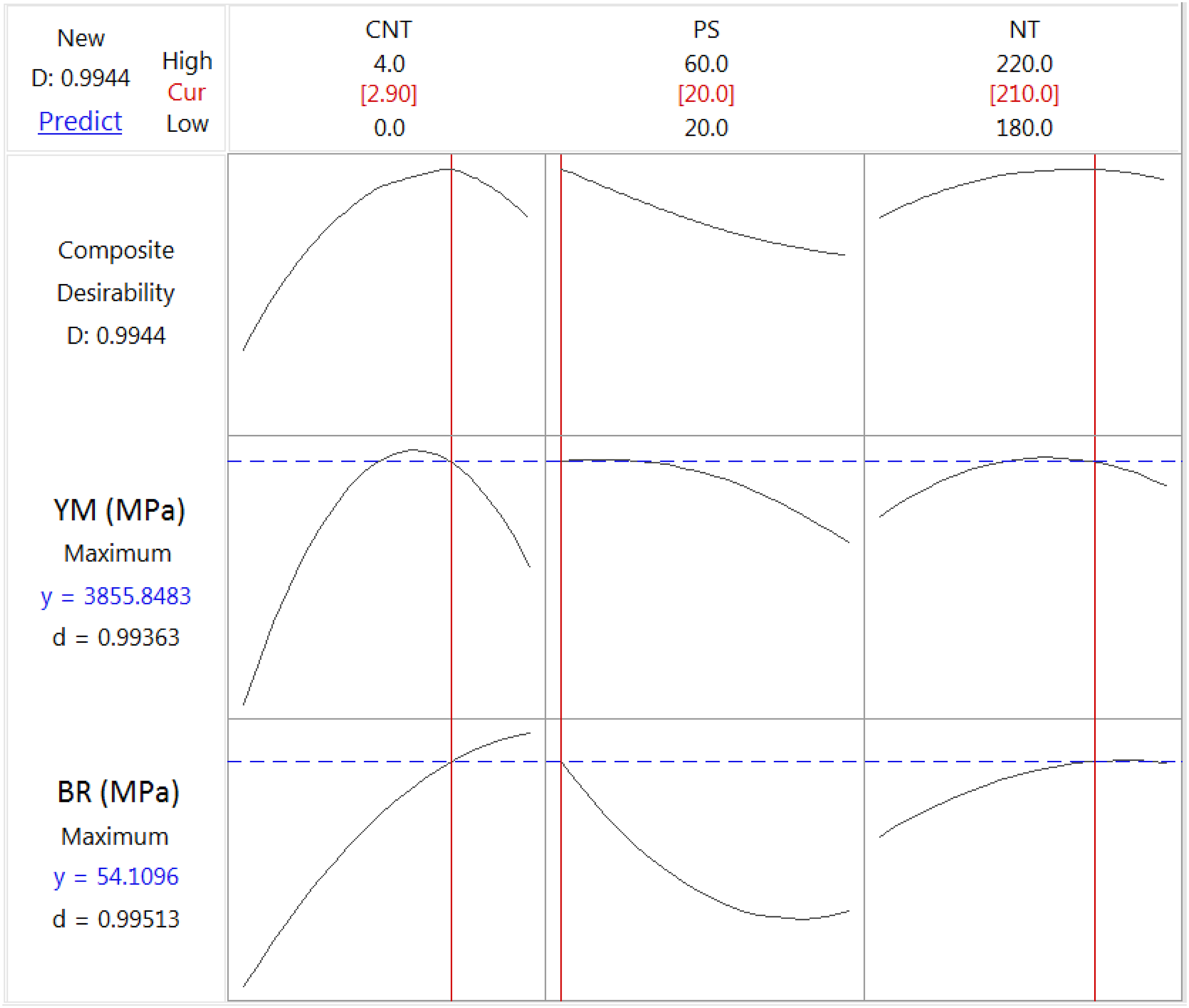
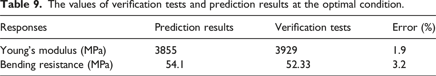
The values of verification tests and prediction results at the optimal condition.
The microstructure of the printed samples has been analyzed in the optimal conditions of the parameters to be compared with other samples. Figure 12 shows the microstructure of the printed sample at the optimal conditions. As can be seen from Figure 12(a), despite the increase of CNT content up to 3 wt%, the nanoparticles are well distributed in the PLA matrix and there is no effect of aggregation. Figure 12(b) shows that at the optimal conditions of the parameters, the interfacial bonding between the filament layers increased and the presence of cracks and voids decreased. The microstructure of the printed sample at optimal conditions with magnifications of (a) 20,000 and (b) 100.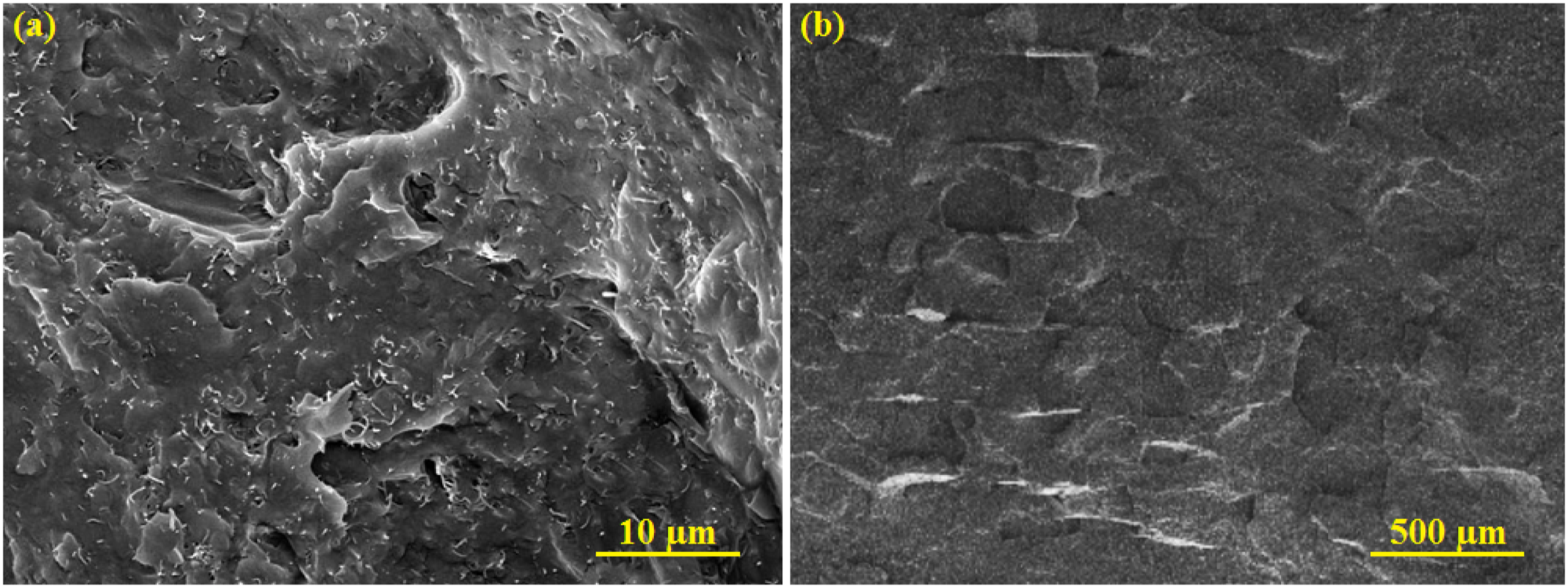
Comparison of mechanical properties of compression molded PLA/CNT samples with 3D printed PLA/CNT at the optimal condition.
Conclusion
In the present study, the Young’s modulus and bending resistance of the PLA/CNT composite improved concurrently by using the response surface method and desirability function technique. The obtained results are summarized as follows: 1- The DSC results showed that an increase in CNT content up to 4 wt% improved the melting and crystallization temperatures of the composites. Moreover, the thermogravimetric analysis indicated that the thermal stability of the composite enhanced with the addition of CNTs in the PLA matrix. 2- The highest Young’s modulus of the composite was attained at a CNT content of 2 wt% owing to good dispersion of the nanoparticles in the PLA matrix, while the Young’s modulus of the composite was maximized at a CNT content of 4 wt% owing to the absorption of some energy by nanoparticles. 3- A rise of printing speed from 20 to 60 mm/s decreased the Young’s modulus and bending resistance of the composite due to the formation of a poor adhesion bonding between filament layers and consequently the formation of cracks and cavities in the microstructure. 4- The increase of nozzle temperature from 180 to 220°C improved the Young’s modulus and bending resistance of the composite, because of the good adhesion of filament layers. 5- The results of optimization demonstrated that the Young’s modulus and bending resistance of the composite can be enhanced simultaneously at a CNT content of 2.9 wt%, printing speed of 20 mm/s and nozzle temperature of 210°C. Under this optimal condition, the Young’s modulus and bending resistance were predicted to be 3855 MPa and 54.1 MPa, respectively.
Footnotes
Declaration of conflicting interests
The author(s) declared no potential conflicts of interest with respect to the research, authorship, and/or publication of this article.
Funding
The author(s) received no financial support for the research, authorship, and/or publication of this article.
Data Availability Statement
The authors confirm that the data supporting the findings of this study are available within the article.