
Abstract
In order to realize the high value-added utilization of coal-based solid waste fly ash (FA) and enhance the performance of polyamide 6 (PA6), three kinds of core-shell structure FA-based composite fillers with different shell morphologies (nano-flake, spherical and rod-like particles) were prepared using FA as raw material, MgSO4, MgCl2, Mg(NO3)2 and NaOH as coating agents, which were noted as composite powder 1 (CP1), composite powder 2 (CP2) and composite powder 3 (CP3). The specific surface areas were enhanced to 97.41, 58.59 and 20.21 m2 g−1 from 1.71 m2 g−1 (FA), while the corresponding pore volumes were increased from 0 to 0.31, 0.22 and 0.06 cm3 g−1. Si-O-C-O-Mg and Si-O-Mg-OH bonds were formed between Si-O-Si, Si-O bonds on the surface of FA and hydrated MgCO3 (MCH), Mg(OH)2 (MH). Three types of CPs were filled into PA6, respectively. After filling, CP2 caused silver grain effect when the material was damaged, which had better toughening effect on the matrix. Compared with pure PA6, the limiting oxygen index of pure MH, FA, CP1, CP2, and CP3 increased by 0.60, 0.70, 1.30, 2.30 and 4.10%, respectively. The thermal deformation temperature was increased by 29.10, 46.20, 53.70, 31.90 and 42.00°C respectively. The melting index decreased by 1.05, 0.70, 0.49, 0.17 and 0.47 g/min, respectively.
Keywords
Introduction
Polyamide 6 (PA6, C6H11NO), also known as polycaprolactam, is extensively utilized in diverse industries including chemical industry, machinery, automobile, and agricultural machinery and equipment. This is attributed to its commendable mechanical properties, chemical stability, electrical insulation, and processing capabilities. Consequently, it has emerged as the most extensively employed engineering plastic worldwide. Despite its exceptional fundamental performance, PA6 often requires toughening, strengthening, and flame-retardant modifications in various application fields.1,2 Common methods of modification include the addition of elastomer, 3 plasticizer, 4 and rigid particles. 5 While the addition of plasticizer and elastomer can enhance the toughness of PA6, it may lead to a slight increase or even decrease in bending strength, tensile strength, thermal deformation temperature and oxygen index. On the other hand, research has demonstrated that incorporating rigid particles into PA6 not only improves its bending strength, tensile strength, thermal deformation temperature and oxygen index, but also reduces the overall cost of PA6.
The output of coal-based solid waste FA produced in coal combustion and utilization is increasing year by year and is expected to reach 925 million tons in 2024. 6 If FA is not treated properly, it can lead to the occupation of valuable land resources and pollution of soil, atmosphere, and water environments. Therefore, finding a high value-added utilization 7 for FA is crucial for the sustainable development of the environment. Previous studies have shown that FA filled polymer exhibits good dispersibility and fluidity, which can enhance the mechanical,8,9 thermal, and flame retardant properties of the polymer.10,11 However, the unmodified FA filled polymer still faces certain challenges. Firstly, the hardness of FA (Mohs hardness 5∼7) is quite high, leading to significant wear of polymer processing equipment and abrasive tools. 12 Secondly, the toughness of the polymer filled with unmodified FA decreased, indicating the need for modification of FA.
Nano magnesium hydroxide (NMH) offers several advantages such as being halogen-free, flame retardant, smoke-reducing, drop-resistant, and having fine particle size with minimal equipment wear. It has a decomposition temperature range of 340 °C–490°C, making it suitable for mixing and processing various plastic resins. Adding NMH to synthetic materials enables them to withstand higher processing temperatures, thus facilitating faster extrusion and shorter molding times. However, it should be noted that NMH exhibits poor dispersibility and processing fluidity in polymers. 13
According to the concept of “particle design”, this study proposes the preparation of composite fillers by coating NMH particles onto the surface of micron-level FA. This approach 14 aims to address issues such as poor dispersion and high cost associated with the use of NMH in polymers, as well as the challenges of high abrasion and poor compatibility of FA-filled polymers. Furthermore, it is expected that the flame retardancy of polymers can be enhanced through this method. 15 It is worth noting that MH exists in various crystal forms, such as spherical, rod, needle, fibrous, hexagonal flake, circular flake, elliptic flake, petal shape, hollow round flake, etc. The morphology of MH plays a significant role in the mechanical and flame retardant properties of the resulting PA6 composites. However, the formation mechanism of FA-coated NMH composite fillers with different morphologies and their structure-activity relationship with the properties of PA6 composites have not been thoroughly investigated. Jiao Lingli et al. demonstrated that MH with diverse morphologies can be synthesized by controlling the reaction conditions. 16
In this study, the author utilized FA as a carrier and coated it with different morphologies of nanoparticles using various magnesium salts and sodium hydroxide as the coating agent. The purpose of this was to enhance the strength and fire resistance of PA6, thereby improving the overall utilization of FA. The FA samples, both before and after modification, were analyzed using various characterization techniques such as Scanning electronic microscopy (SEM), Energy-dispersive X-ray spectrometry (EDS), X-ray diffraction (XRD), X-ray photoelectron spectroscopy (XPS), Fourier transform infrared (FTIR), and BET. These analyses allowed for a comprehensive evaluation of the changes in surface morphology, crystal structure, functional group composition, specific surface area, and pore structure characteristics of the different magnesium salts before and after modification. Furthermore, the study investigated the mechanical properties, thermal deformation temperature, and melting index of PA6 filled with the different modified powders. The aim was to understand the influence mechanism of the modified FA with different morphologies on the properties of PA6. Overall, this research provides a novel approach to enhance the comprehensive utilization of FA.
Experiment
Materials and reagents
FA cenospheres, produced by burning in pulverized coal furnace, with the grain size 5000 mesh and specific surface area 1.71 m2 g−1, were provided by Shanghai Grunya Nanomaterials Co. Ltd. And their chemical composition mass fraction was as follows: SiO2 (51.85%), Al2O3 (37.06%), Fe2O3 (2.37%), TiO2 (1.32%), CaO (3.04%), MgO (1.13%), K2O (1.36%), Na2O (0.691%). As shown in Figure 1, the main crystalline phases of FA were mullite and quartz. NaOH, analytical pure, purchased from Sinopharm Chemical Reagent Co., Ltd. Magnesium sulfate heptahydrate, purchased from Wuxi Yatai Combined Chemical Co., Ltd. Magnesium chloride, purchased from Tianjin Guangfu Fine Chemical Research Institute. Magnesium nitrate hexahydrate, purchased from Tianjin Chemical Reagent Factory. PA6 (YH800), purchased from Yueyang Petrochemical Co., Ltd XRD spectrum of FA and CFA.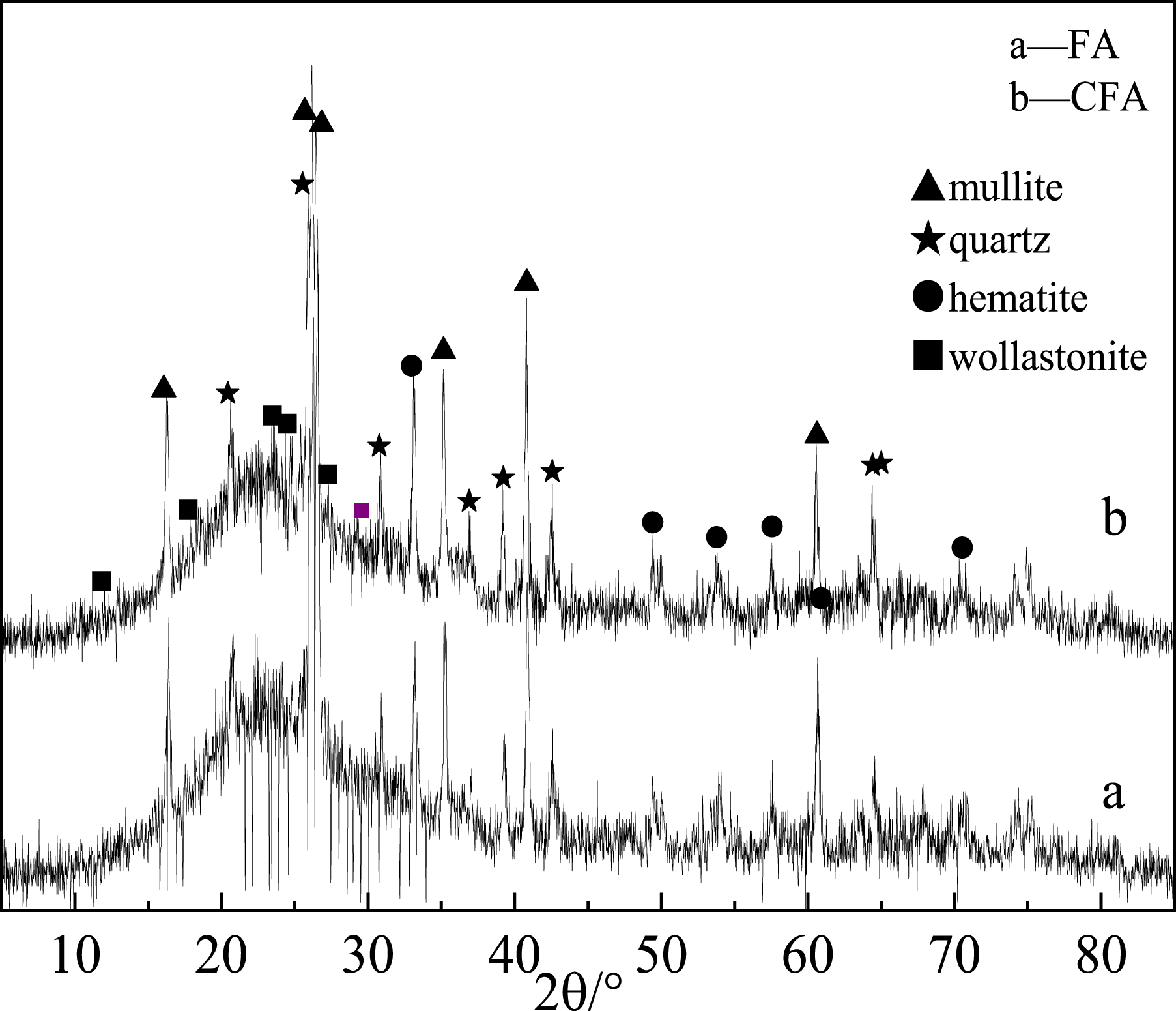
Preparation of three types of CPs
The calcined fly ash (CFA) and water were configured into a good dispersing suspension at the ratio of 1:5, and then placed in a three-port flask, heated and stirred in a water bath. When the temperature reached 90°C, 0.3 mol L−1 NaOH solution and 0.15 mol L−1 magnesium salt solution were added to CFA suspension by a constant flow pump with a drop acceleration of 5 mL min−1. After the coating agent was added, the pH value was adjusted to 10. Keep the temperature unchanged and continue the reaction for 90 min, and then the suspension was washed, filtered, dried, dispersed and depolymerized to obtain FA based CPs. The three modified powders obtained by the reaction of MgSO4, MgCl2, Mg(NO3)2 and NaOH were denoted as CP1, CP2 and CP3, respectively.
Preparation of PA6 Filled with CPs
PA6 was dried in a vacuum oven at 90°C for 24 h, and then pure MH, CFA, CP1, CP2 and CP3 were blended with PA6 in a twin-screw extruder (LHFD1-130,718, Lab. Tech Engineering Company Ltd) with a volume fraction of 4%. Extrusion temperature was 190°C, 200°C, 210°C, 220°C, 230°C, 240°C, rotational speed was 240 r min−1, and feeding speed was 15 r min−1. After the blended extrusion granulation, it was dried in a vacuum oven at 90°C for 24 h, and then injected on micro injection molding machine (SAS-20, Wuhan Ruiming Experimental Equipment Manufacturing Co., Ltd) to obtain the test spline, and the injection temperature was 210°C, 220°C, 230°C, 240°C.
Material characterization and properties test
The FA before and after modification was characterized. The chemical composition of FA was tested by Thermofisher 3600 X-ray fluorescence spectrometer. The morphology of the samples was tested by the Gemini300 emission scanning electron microscope (German Carl Zeiss), and the surface chemical composition of the samples was tested by the EDS with the scanning electron microscope. The elemental composition and chemical states of the samples were analyzed by Thermofisher ESCALAB 250XI X-ray photoelectron spectroscopy. The crystal of the samples was tested by the MiniFlex600 X-ray diffractometer made by Rigaku Company in Japan. The surface functional groups of the samples were tested by using Nicolet 670 Fourier transform infrared spectrometer. The thermogravimetric analyzer HCT-1 produced by Beijing Hengjiu Scientific Instrument Factory was used to test the TG of the samples. The particle size distribution of the samples was tested by the laser particle size analyzer Stersizer 3000. The specific surface area and pore size distribution of the samples were tested by JW-BK static nitrogen adsorption apparatus from Beijing Jingwei Gaobo Science and Technology Co., Ltd.
The properties of PA6 filled with CP were tested. The PA6 tensile profile was tested on an emission scanning electron microscope (JSM-7001F, Japan Electronics Corporation). The heat distortion temperature (HDT) was measured on the thermal deformation test machine (ZWK1000, Meters Industrial Systems (China) Co., Ltd) with a heating rate of 120°C h−1 and a load of 0.45 MPa according to GB/T1634.1-2004. The tensile properties were tested on the electronic universal testing machine (C43.50, Meters Industrial Systems (China) Co., Ltd) at the speed of 50 mm min−1 according to GB/T1040-92. The bending properties were tested on electronic universal testing machine (C43.50, Meters Industrial Systems (China) Co., Ltd) at the speed of 2 mm min−1 according to GB/T1040-92. The impact toughness was tested on the pendulum impact tester (ZBC8500, Meters Industrial Systems (China) Co., Ltd) according to GB/T1043-93 standard. The melt index was tested on the melt index meter (2.16 kg, ZRZ2452, Meters Industrial Systems (China) Co., Ltd) at 240°C according to GB/T3682-2000. The limit oxygen index was tested on the oxygen index tester (XWR-2046, Cangzhou Jilu Experimental Instrument Co., Ltd) according to GB/T2406-80.
Results and discussion
SEM, EDS, FTIR of CFA, CP1, CP2 and CP3
Figure 2(a) and (b) showed the SEM images of CFA, which mostly consisted of regular spherical particles with an average size of about 1.2∼2 μm. Figure 2(c) and (d) displayed the SEM images of CP1, where the average particle size was approximately 1.5 μm and the surface was coated with flake nanoparticles. Figure 2(e) and (f) depicted the SEM images of CP2, with an average particle size of around 2 μm and a surface coated with spherical nanoparticles. Finally, Figure 2(g) and (h) exhibited the SEM images of CP3, showing an average particle size of about 2 μm and a surface coated with rod-like nanoparticles. These images clearly demonstrated that the morphology of nanoparticles on the surface of CFA was greatly influenced by the magnesium salt anion. SEM of CFA (a), (b), CP1 (c), (d), CP2 (e), (f) and CP3 (g), (h).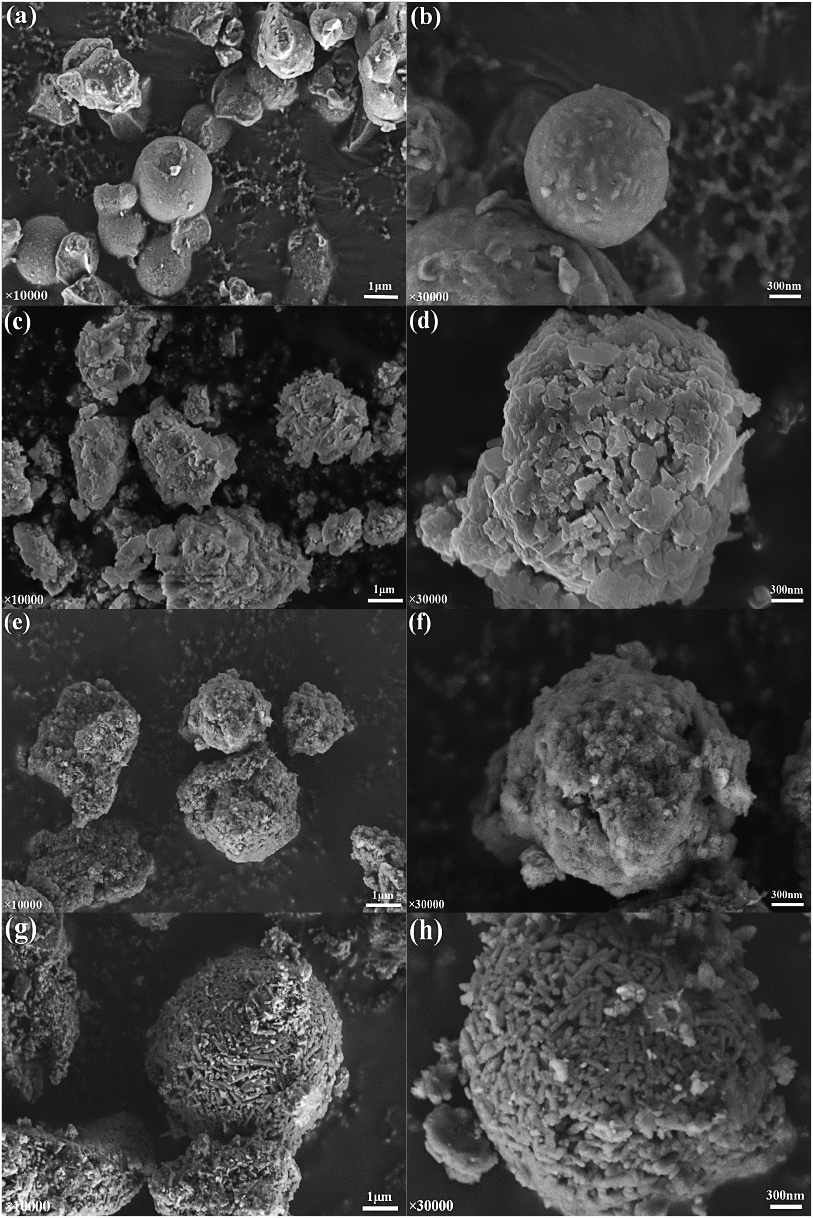
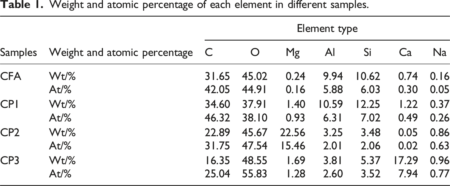
Weight and atomic percentage of each element in different samples.
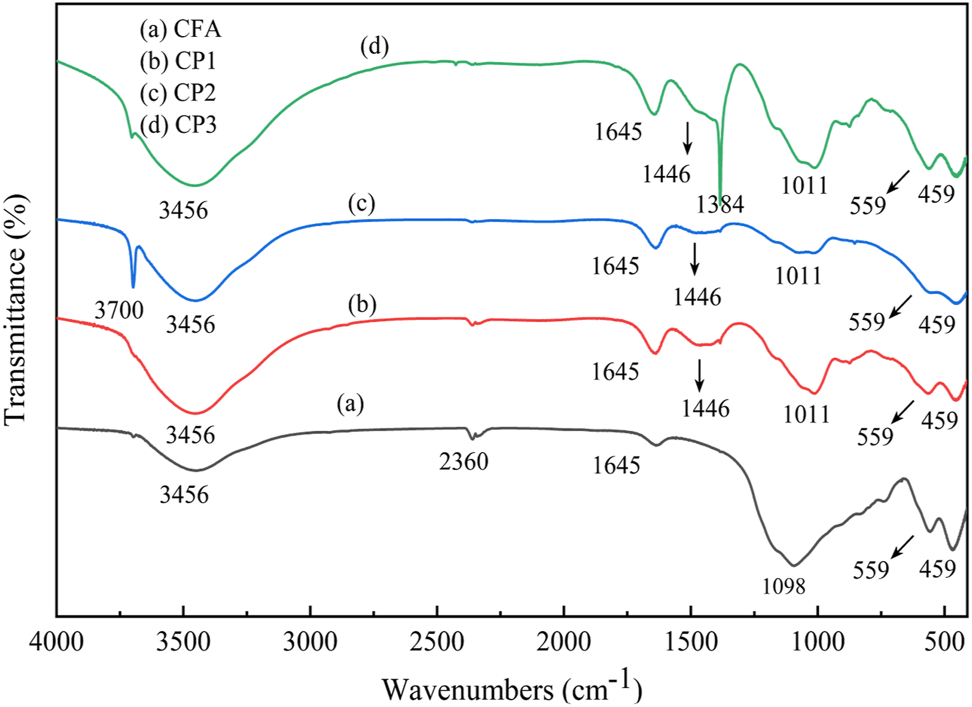
FTIR of CFA, CP1, CP2 and CP3.
In Figure 3(a), the wavenumbers at 3456 cm−1 and 1645 cm−1 corresponded to the O-H vibration characteristic absorption peaks of adsorbed water in CFA. 18 The wavenumbers of 1098 cm−1 and 459 cm−1 represented the characteristic absorption peaks of Si-O-Si asymmetric stretching vibration and Si-O bending vibration. The characteristic absorption peak of Al-O stretching vibration at wavenumber 559 cm−1 corresponded to [AlO6], indicating the presence of mullites in CFA.
Compared with curve a, curve b exhibited a new characteristic absorption peak at the wavenumber 1446 cm−1, which was identified as the characteristic absorption peak of carbonate bending vibration. 19 This could be attributed to the reaction between the generated MH and CO2 on the CFA surface, resulting in the formation of MCH. The strength of the characteristic absorption peaks related to O-H stretching vibration at 3456 cm−1 and O-H bending vibration at 1645 cm−1 increased, indicating an increase in the surface crystal water of CP1. The wavenumber of 1098 cm−1 shifted to 1011 cm−1, accompanied by a decrease in peak strength. Additionally, the peak strength at 459 cm−1 also decreased, suggesting the breakage of Si-O-Si and Si-O bonds, and the formation of a new Si-O-Mg-C-O bond between Si-O-Si and MgCO3. The peak strength further confirmed that the particles on the surface of CFA were MCH.
In curve c, the characteristic absorption peak at 3700 cm−1 corresponded to the -OH antisymmetric stretching vibration. This absorption band exhibited strong intensity, sharpness, and narrowness, which were typical characteristics of an O-H bond. Compared with curve a, the peak strength at 3456 cm−1 and 1645 cm−1 increased, while the peak strength decreased compared with curve b, indicating that the surface crystal water of CP2 was more than that of CFA, but less than that of CP1. Compared with curve b, the peak strength at wave number 1446 cm−1 was smaller, indicating that a small amount of hydrated magnesium carbonate was generated. The wavenumber of 1098 cm−1 moved to 1011 cm−1, and the peak strength decreased. At the same time, the peak strength also decreased at 559 cm−1 and 459 cm−1, indicating that the Si-O-Si, Al-O and Si-O bonds broke, Si-O-Mg-C-O and Si-O-Mg-OH bonds were formed with MgCO3 and MH. It can also be seen from the peak strength that the surface of CFA in CP2 was coated with a large amount of MH and a small amount of MCH.
Compared with curve a, the peak strength at 3456 cm−1 and 1645 cm−1 increased, while it decreased compared with curve b. This suggested that CP2 had more surface crystal water than CFA, but less than CP1. Additionally, the peak strength at wave number 1446 cm−1 was smaller compared with curve b, indicating the presence of a small amount of hydrated magnesium carbonate. The wavenumber of 1098 cm−1 shifted to 1011 cm−1 and the peak strength decreased, along with decreased at 559 cm−1 and 459 cm−1. These changes suggested the breaking of Si-O-Si, Al-O, and Si-O bonds, as well as the formation of Si-O-Mg-C-O and Si-O-Mg-OH bonds with MgCO3 and MH. The peak strength also indicated that the surface of CFA in CP2 was coated with a large amount of MH and a small amount of MCH.
From curve d, it can be observed that the characteristic absorption peak of carbonate bending vibration in CP3 disappeared at 1446 cm−1. Instead, a new narrow and sharp peak appeared at 1384 cm−1, which was identified as the C-O bond. The wavenumber of 1098 cm−1 shifted to 1011 cm−1 and the peak strength decreased. At the same time, the peak strength at the wavenumber 459 cm−1 also decreased, indicating that the Si-O-Si and Si-O bond broke, and a new Si-O-C-O-Mg bond was formed with MgCO3. Compared with curves b and c, the peak strength at the wavenumber 3456 cm−1 was larger, indicating that there was more crystal water. Consequently, it can be observed that the surface of CFA in CP3 was extensively coated with a significant amount of MCH and a lesser amount of MH.
Particle size analysis
Particle size analysis of FA before and after modification was conducted by particle size analyzer, as shown in Figure 4. As illustrated in Figure 4, the particle size of CFA was predominantly distributed within the range of 1.11∼1.48 μm, with the highest concentration of particles around 1.28 μm. The particle sizes of 1.11 μm and 1.48 μm accounted for 29.1% and 26.4% respectively, indicating a relatively even distribution. The particle size of CFA corresponded to the range observed in the scanning electron microscope diagram. Moving on to CP1, the particle size distribution was mainly focused on the range of 1.48 μm to 1.99 μm, with the majority of particles measuring 1.72 μm, which accounted for nearly 50% of the distribution. CP2 exhibited a wider particle size distribution of ranging from 1.72 μm to 3.58 μm, with over 50% of particles measuring approximately 2.5 μm, making it relatively larger compared with other CPs. The particle size of CP3 mainly ranged from 1.28 μm to 1.72 μm, and the distribution was uniform. The curves of the three types of CPs shifted to the right, indicating larger particle sizes compared with CFA in each number fraction. The particle size sequence of different particle size fraction is: CP2>CP1>CP3>CFA, suggesting that nanoparticles were successfully loaded onto the CFA surface, which was consistent with the SEM results. Particle size distribution of CFA, CP1, CP2 and CP3.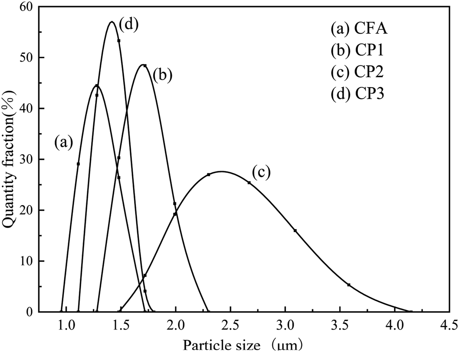
Analysis of specific surface area and pore volume
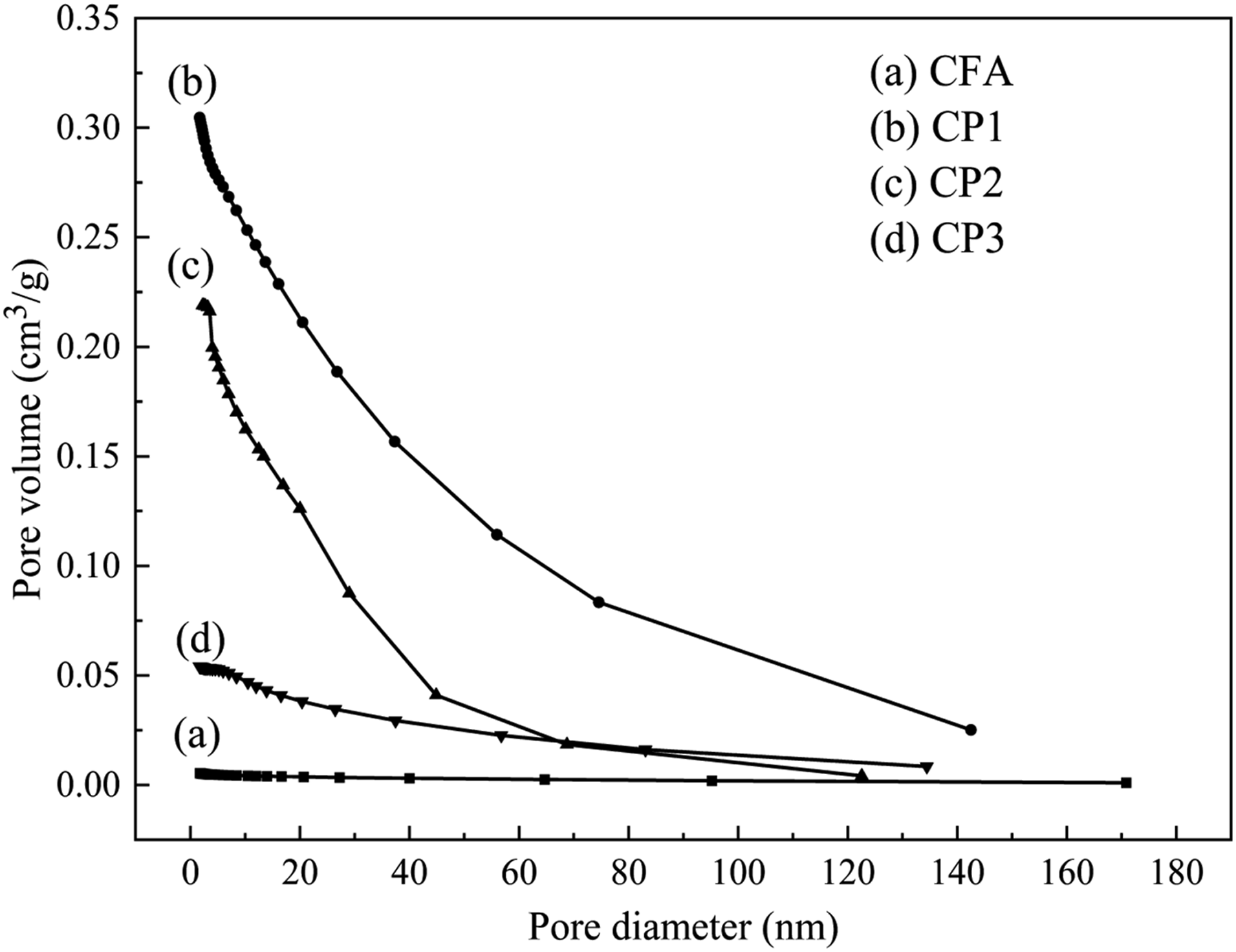
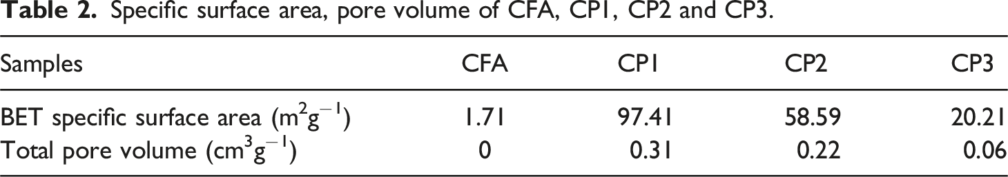
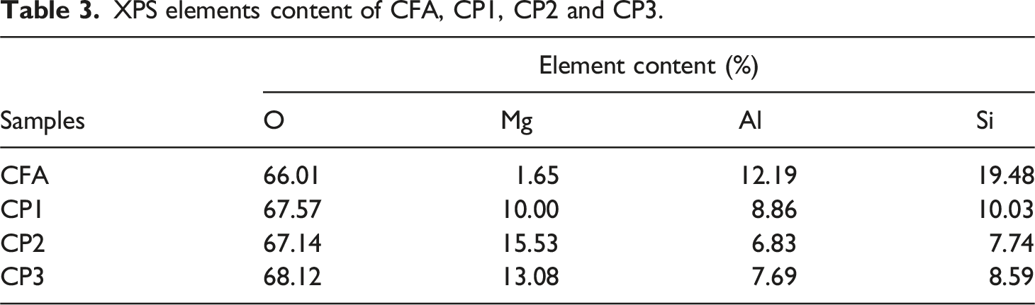
The isothermal adsorption and desorption curves of FA and CPs were measured, as depicted in Figure 5. The gas subjected to adsorption was nitrogen and the process was conducted at the temperature of 77 K, while the surrounding temperature was maintained at 300 K. The pore diameter and pore volume of FA and CPs were presented in Figure 6. Additionally, the specific surface area and pore volume were illustrated in Table 2. As observed in Figure 5, CFA, CP1, CP2 and CP3 exhibited typical IV adsorption isotherms with h3 hysteresis curves, which may be attributed to their considerable mesoporous size. As shown in Table 3, CFA had no micropores (0 cm3 g−1) and a specific surface area of only 1.71 m2 g−1. CP2 and CP3 displayed adsorption desorption isotherms characteristic of mesoporous materials (2-50 nm), with a micropore volume of 0 cm3 g−1. In addition to mesoporous, CP1 also contained some macropores. The BET surface area of CP1, CP2, and CP3 was 97.41, 58.59, and 20.21 m2 g−1, respectively, which enhanced the interface performance of PA6. It was apparent from Figure 5 that when the pore diameter was the same, the order of pore volume was as follows: CP1> CP2> CP3>CFA. The pore volume was increased from 0 cm3g−1 (CFA) to 0.31 cm3 g−1 (CP1), 0.22 cm3 g−1 (CP2) and 0.06 cm3g−1 (CP3), respectively. The rich pore structure was capable of absorbing carbon dioxide and carbon monoxide gas produced during combustion. Isothermal adsorption and desorption curves of CFA, CP1, CP2 and CP3. The pore diameter and volume of CFA, CP1, CP2 and CP3. Specific surface area, pore volume of CFA, CP1, CP2 and CP3. XPS elements content of CFA, CP1, CP2 and CP3.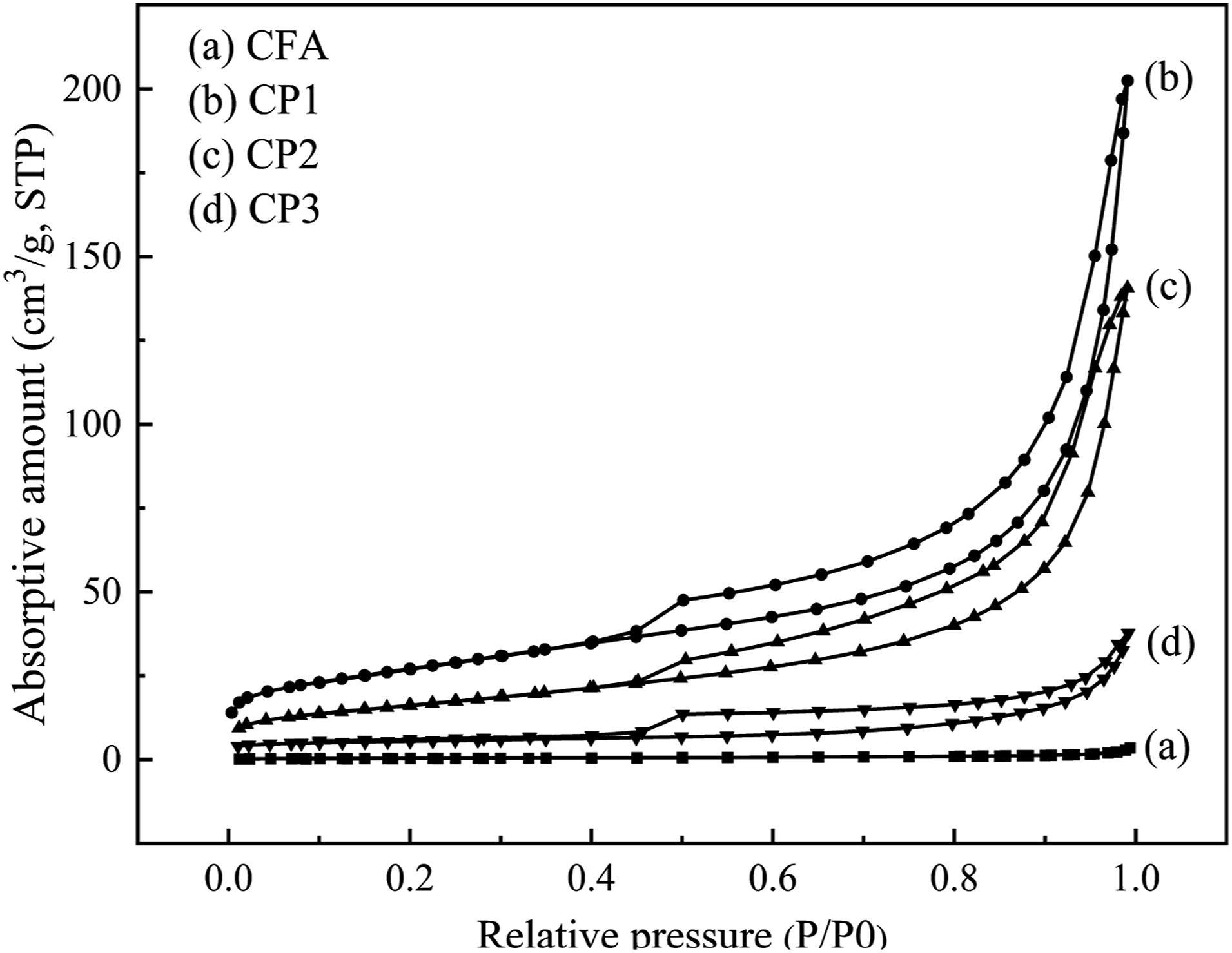
X-ray photoelectron spectroscopy analysis
X-ray photoelectron spectroscopy (XPS) was utilized to analyze the surface composition of FA before and after modification, as depicted in Figure 7 and Table 3. Figure 7(a) revealed that the unmodified CFA surface mainly consisted of O, Si, Al and trace amounts of Mg. The highest intensity peak at a binding energy of 531.5 eV corresponded to O1s, which represented the largest content ratio of oxygen. Figure 7(b)–(d) demonstrated that the CPs surface primarily contained O, Mg, Si, and Al elements. The appearance of a new peak at 1303.5 eV indicated the presence of Mg1s binding energy. The decrease in Si and Al content and the increase in O and Mg content suggested the coating of the CFA surface with a magnesium complex. XPS of CFA, CP1, CP2 and CP3.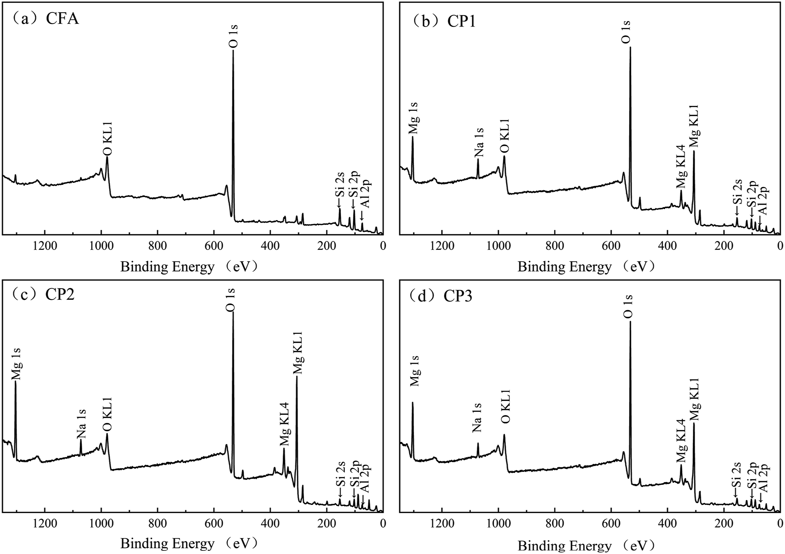
X-ray diffraction analysis analysis
X-ray diffraction analysis was performed on the crystal phase of CFA, CP1, CP2, and CP3, and the results were presented in Figure 8. From Figure 8, it can be observed that both amorphous and crystalline substances were presented in CFA, CP1, CP2, and CP3. The diffraction peaks in CFA were identified as orthorhombic mullite (card number: 841,205) and tripartite quartz (card number: 820,512).
20
Comparing with curve a, the new diffraction peaks of curves b, c, and d at 29.4° were attributed to MCH,
21
indicating that the surfaces of CP1, CP2, and CP3 were coated with MCH. However, CP2 had a lower MCH coating compared with the other two. Furthermore, curve c exhibited numerous sharp MH diffraction peaks at 18.6°, 38.1°, 50.9°, and 58.8°.
22
These peaks corresponded to the crystal planes (001), (101), (102), and (110), respectively, with the sharpest peak observed on (101). This suggested that the surface of CP2 was predominantly coated with MH particles and a small amount of MCH particles. The absence of an MH diffraction peak in CP1 may be attributed to the adsorption of carbon dioxide in the FA hole during the coal combustion process to generate FA and carbon dioxide. This can be observed from the infrared spectrum of curve a in Figure 3. On the other hand, the reaction of magnesium salt solution with sodium hydroxide solution and CO2 resulted in the formation of MCH. Based on the analysis of curve d in Figure 8 and infrared spectrum in Figure 3, it is evident that a significant amount of MCH particles, along with a small number of MH particles, were coated on the surface of CP3. However, due to the limited quantity of MH, no MH diffraction peak could be detected in the XRD. XRD of CFA, CP1, CP2 and CP3.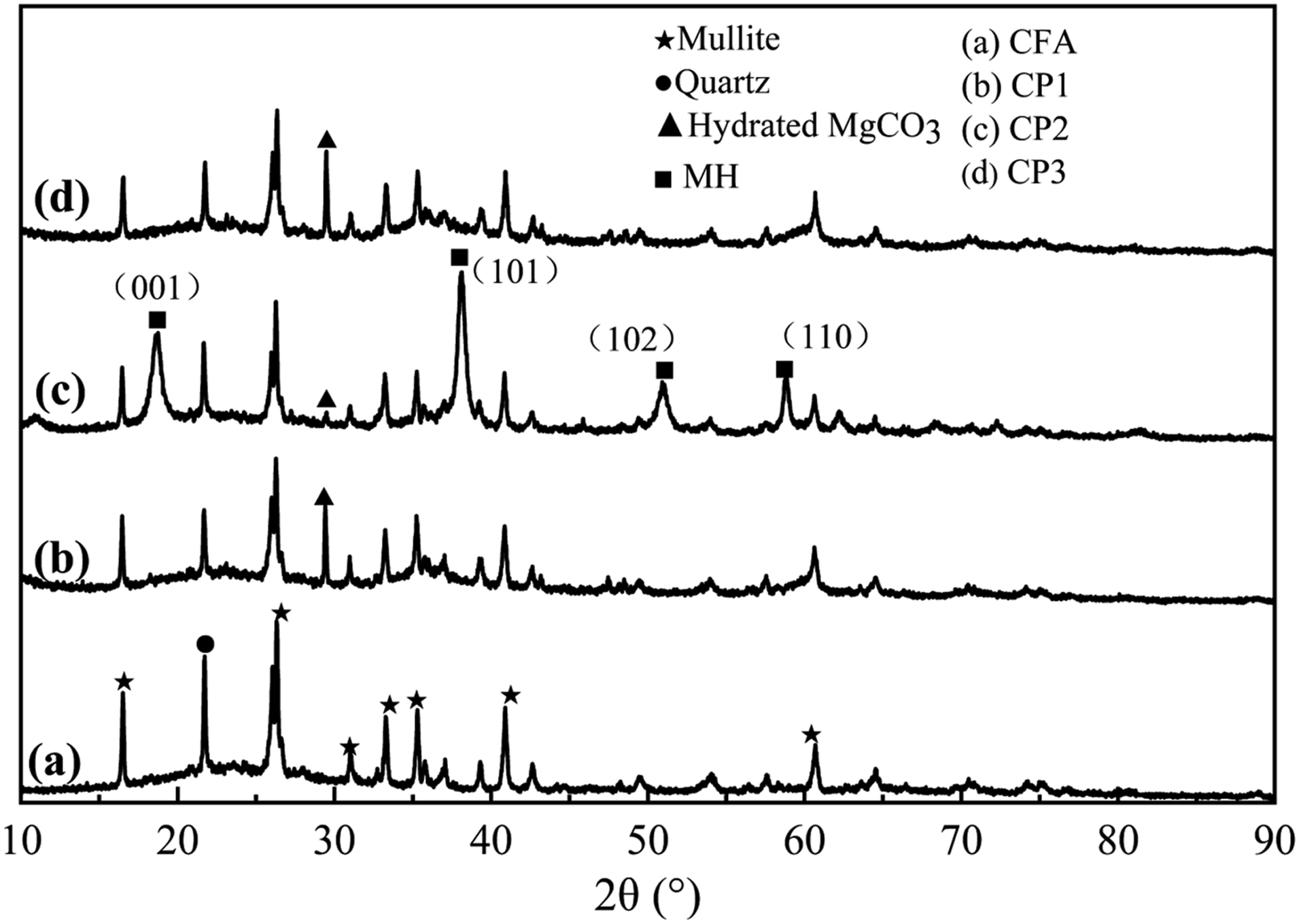
Preparation mechanism of CPs
Mechanism of heterogeneous nucleation (HN)
The HN method involves using a coating agent to form non-uniform nucleation and grow on the matrix, following the Lamer crystallization process theory. Compared with homogeneous nucleation, HN is a simpler process as it does not require nucleation work. Instead, the coating agent preferentially nucleates on the matrix to form the coating layer. Initially, the surface energy of the shell material is high, leading to its adsorption on the surface of the nuclear material particles. This reduces the surface energy and free energy of the system, promoting stability. Subsequently, after washing and drying, the CPs with a core-shell structure are formed. When surface coating is conducted using the HN method, it is crucial to control the concentration of the shell material and induce HN on the surface of the nuclear material to reduce surface energy and system free energy. The author has conducted a study on the impact of magnesium salt concentration, droplet acceleration, reaction temperature and pH value on the whiteness of CPs, and have identified the optimal conditions for the preparation of CPs. At pH = 10, the surface of CFA exhibited a negative charge, while the surface of MH displayed a positive charge. The charges between the shell and nuclear materials were opposite, rendering both particles unstable. However, the electrostatic force brought them together, neutralizing the surface charges. This not only strengthened the binding force between the core and shell, but also reduced the agglomeration of similar ions. Furthermore, a new compound, Si-O-C-O-Mg (CP1), formed between Si-O-Si and Si-O on the surface of CFA and MCH. Similarly, the formation of Si-O-Mg-OH and Si-O-C-O-Mg (CP2 and CP3) occurred between Si-O-Si and Si-O on the surface of CFA and MH, MCH, as depicted in Figure 9. Consequently, a stable coating was established on the surface of the CFA. Schematic diagram of preparation mechanism of CPs. (a) CP1. (b) CP2. (c) CP3.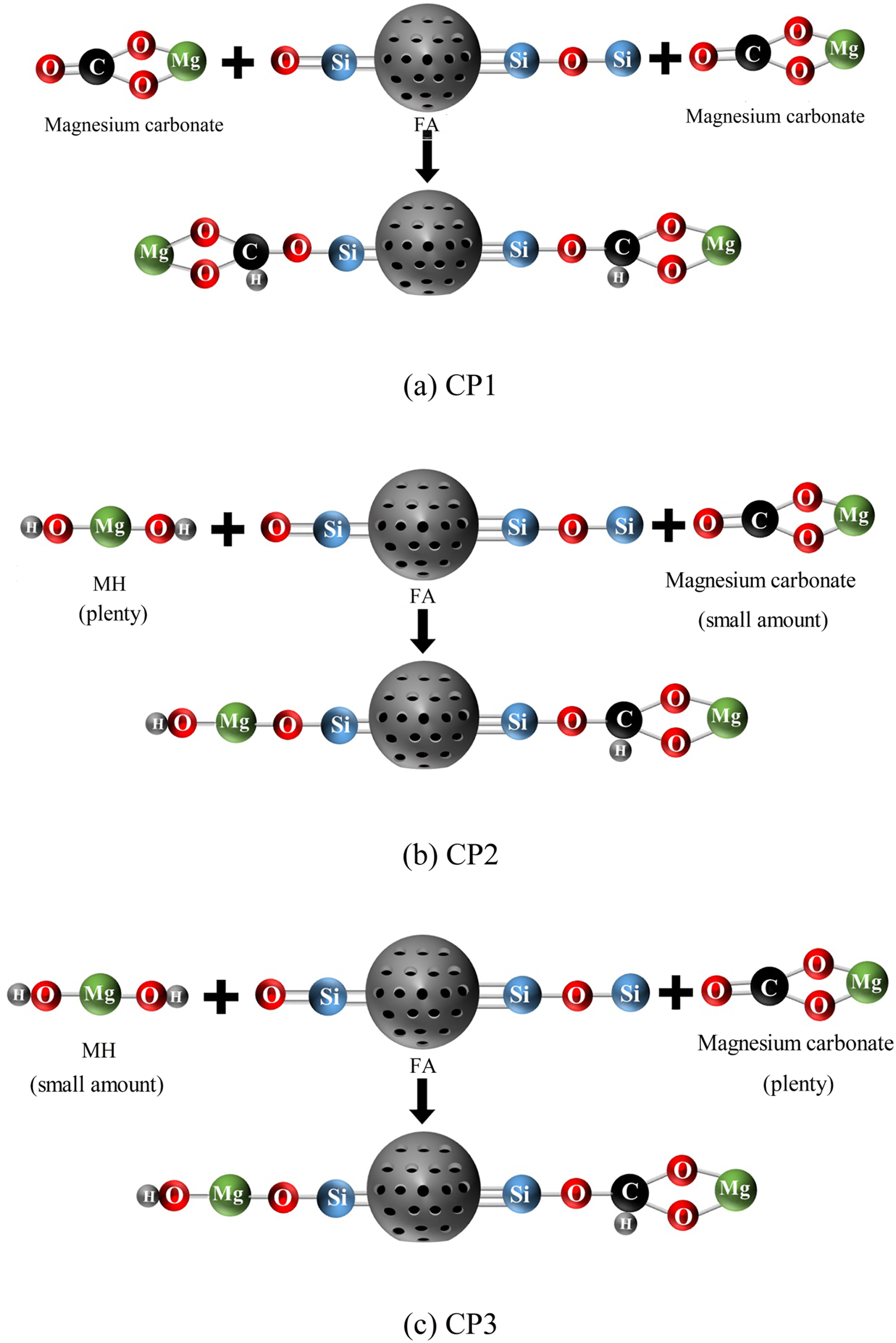
Effect of different magnesium salt anions on crystal growth and morphology of nano-shell particles on CPs surface
MH was classified as a polar ionic crystal, following Pauling’s rule 23 for crystal structure and growth. The unique structure of MH exhibited a variation along its polar axis, with Mg2+ ions on the positive side and OH− ions on the negative side. The influence of different magnesium salts on the morphology of MH primarily manifested during the crystal growth process. Electrostatic interactions resulted in the adsorption of various magnesium salt anions on the surface of MH. This adsorption process subsequently affected the nucleation and growth rate of the crystal, effectively controlling the overall growth habit and resulting in diverse morphologies of MH. 24 These morphologies can include hexagonal shapes, spherical forms, rod-like structures, acicular appearances, fibrous arrangements, and more.
Based on the information presented in Figure 2(d), CP1, where MgSO4 was used as the magnesium salt, exhibited an irregular thin sheet as the coating layer. Analyzing Figure 7(b), it became apparent that the (101) crystal surface displayed the highest peak strength and the most intact crystal shape, while the (001) surface exhibited the slowest growth rate, and the (110) surface demonstrated the fastest growth rate. The formation of the sheet-like MH crystal in CP1 primarily occurred along the (110) surface. With the addition of the SO42- anion, a weak covalent ionic bond (O-Mg and H-Mg) was introduced to the (001) and (101) surfaces of the MH crystal. The electronegativity of SO42- was comparatively lower than that of Cl− and (NO)32-. Therefore, the (001) and (101) surfaces were relatively less affected. Moreover, the crystal structure of MH in CP1 exhibited a connection pattern involving shared top angles rather than regular octahedral connections, resulting in three Mg2+ ions being connected to one -OH along the X and Y axes. This particular bond configuration contributed to high stability, facilitating rapid growth along the horizontal axis direction, which corresponded to the (110) surface. The vertical axis direction (001) surface was not connected by chemical bonding and had poor stability, so this surface grew slowly or even not, which made the thickness of (001) surface small, thus the crystal was flaky. 25 The final CP1 cladding layer was MCH due to the participation of CO2 in the preparation process.
Based on Figure 2(f), the coating layer of MH formed spherical shapes through the reaction of MgCl2 and NaOH in CP2. The pH value of the MH powder in the solution reached 12 at the isoelectric point. When the pH value of the solution exceeded 13, the surface charge on the MH particles became negative. As the pH value increased, the concentration of OH− ions in the solution also increased, leading to supersaturation and rapid nucleation. This resulted in small grain size and irregularly shaped crystal nuclei. During nucleation, Cl− had a greater impact on the (001) and (101) surfaces of the crystal compared with SO42-, causing increased energy and poor surface stability. Therefore, cations in the solution would migrate to the growing crystal. Due to the high concentration of cations in the solution and small hydration radius, Na+ would be adsorbed on all surfaces of the crystal nucleus without selectivity. The entry and subsequent growth of Mg2+ were hindered. In order to reduce the surface energy of particles, the homogenous crystal particles of different phases tended to aggregate, forming spherical structures. 26 Additionally, under the hydrothermal condition of 90°C, NaOH and MgCl2 were steadily added into the CFA suspension, causing the solution concentration to always remain in the state of crystal nucleus precipitation. As a result, the crystal particle size significantly increased, the diffraction peak intensity ratio of the (001) surface to the (101) surface increased, and the (001) surface with weak polarity became more exposed. On the other hand, the growth of the surface (101) with strong polarity was inhibited. The presence of microscopic internal stress on the surface of MH particles led to particle agglomeration, 27 resulting in the formation of spherical structures. Furthermore, due to the presence of CO2, a minor portion of MH underwent conversion to MCH.
According to Figure 2(h), the coating layer formed through the reaction of Mg(NO3)2 and NaOH in CP3 exhibited a one-dimensional rod-like structure. The (001) surface peak of the rod-like crystal showed the highest strength, indicating that the crystal form was the most complete. Comparatively, the (101) surface peak was weaker than that of the flake, and the ratio of I (101)/I (001) was smaller than that of flake MH. The crystal growth direction changed, resulting in a higher exposure of the (001) surface and less exposure of other crystal surfaces, particularly the (101) surface growth was inhibited. Consequently, new MH grew predominantly along the (001) surface. After the adsorption of (NO)32- on the MH crystal, the weak covalent ionic bond O-Mg was introduced to the (001) and (101) crystal surfaces. The presence of (NO)32- enhanced the ionic properties of the (001) and (101) crystal surfaces, leading to the formation of a new rod-like Mg-O-C structure model through the combination of O-Mg and C in CFA. 28 As a result, a coating layer consisting of rod-like MCH and a small amount of MH was obtained.
Properties and mechanism of PA6 filling with CFA and CPs
Mechanical properties of PA6 filled with different powder.
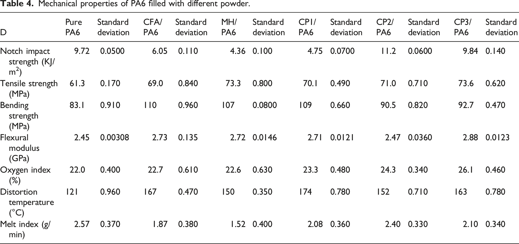
It can also be seen from Table 4 that the ultimate oxygen index of pure PA6 was 22.00%, and the ultimate oxygen index was increased by 0.60%, 0.70%, 1.30%, 2.30%, and 4.10% after filling with pure MH, CFA, and CPs, respectively. It was evident that the oxygen index of PA6 filled with different powders was significantly higher than that of pure PA6. Additionally, PA6 filled with FA-based CPs with three types of morphologies exhibited a higher oxygen index compared with PA6 filled with pure MH and CFA. The thermal deformation temperature of pure PA6 was 120.50°C. However, after filling with pure MH, CFA, CP1, CP2 and CP3, the thermal deformation temperature increased by 29.10°C, 46.20°C, 53.70°C, 31.90°C and 42.00°C, respectively. This indicated that the thermal deformation temperature of PA6 can be improved after filling with CFA and CPs, expanding its application range to include automotive and other fields. The melt index of pure PA6 was 2.57 g min−1. After filling with pure MH, CFA, CP1, CP2 and CP3, the melt index was decreased by 1.05 g min−1, 0.70 g min−1, 0.49 g min−1, 0.17 g min−1, 0.47 g min−1, respectively. Notably, the melt index of PA6 filled with CPs was higher than that of PA6 filled with MH or CFA. The results indicated that the dispersibility of PA6 filled with CPs was superior to that of PA6 filled with CFA or pure MH, resulting in an improvement in processing properties.
Figure 10 showed the SEM images of tensile sections of pure PA6 and PA6 filled with CFA and CPs. Figure 10(a) showed the tensile section of pure PA6, revealing that at room temperature, the cracks and lines in the tensile section of pure PA6 were relatively small, and the section was slightly rough. Figure 10(b) illustrated the SEM image of tensile section after PA6 filled with pure MH. The image revealed that cracks and lines in the tensile section of the composite materials after filling with pure MH became larger, with some MH particles exposed outside, and plastic tear marks presented. Figure 10(c) showed the SEM image of the tensile section of PA6 filled with CFA. It can be observed that the cracks in the tensile section of the composite materials after filling with CFA became more, the lines became larger, and the section became rougher. In addition, due to the weak bond between the interface of CFA and the base PA6, it did not induce a silver pattern or yield deformation in pure PA6. Figure 10(d) displayed the SEM image of the tensile section of PA6 filled with CP1. The tensile section of the composite materials after filling with CP1 became rougher, the cracks and lines became larger. In addition, CP1 did not cause the silver pattern or yield deformation of pure PA6. The SEM image in Figure 10(e) showed that the tensile section of PA6 filled with CP2 had a band-like distribution of fold cracks, which resulted from plastic deformation during material stretching. These fold cracks can act as a flexible layer during the fracture process, triggering the silver pattern effect and providing energy absorption and stress transfer, thereby enhancing toughness.
32
Figure 10(f) showed the SEM image of the tensile section after filling PA6 with CP3. It revealed that there was a small amount of particle agglomeration in the composite materials, leading to separation between the particles and the matrix PA6 when subjected to external forces. This resulted in the formation of defects and fracture within the composite materials.
33
Compared with pure PA6, filling with different materials increased the specific surface area, thereby increasing the contact points or interaction points between the particles and the organic matrix. This led to a rougher tensile fracture surface, dispersing the stress exerted on the composite material. It enhances the interaction between the filler particles and the PA6 matrix, significantly improving the interface condition between the filler particles and the organic matrix, thereby enhancing the mechanical properties of the material. SEM of tensile cross-sections of PA6 filled with different powder” in Figure 10 is modified to “SEM of tensile cross-sections of (a) pure PA6, (b) PA6 filled with Pure MH, (c) PA6 filled with FA, (d) PA6 filled with CP1, (e) PA6 filled withCP2 and (f) PA6 filled with CP3.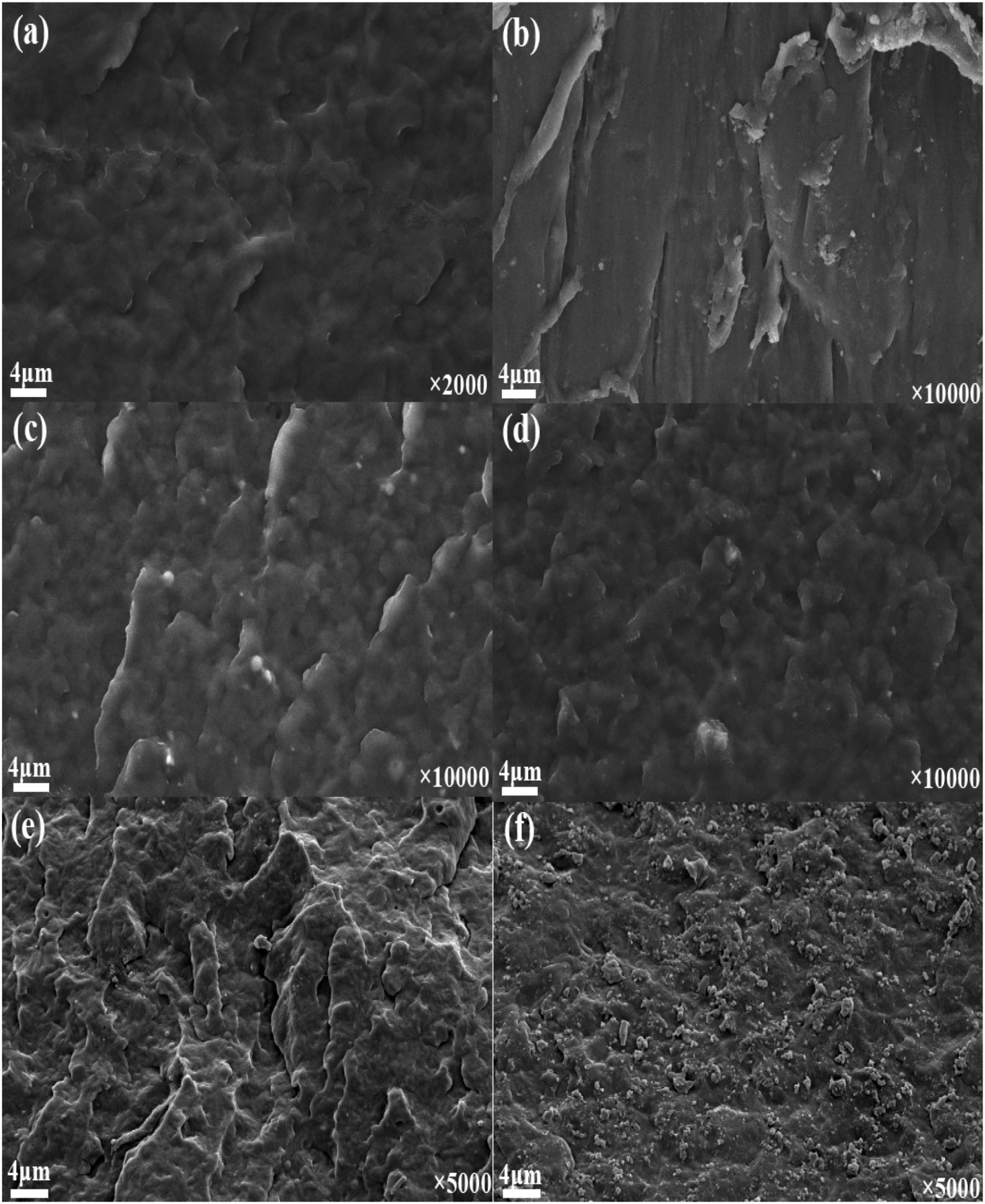
Figure 11 presented the TG curves of FA and CFA. From curve (a), it was observed that FA experienced a heat loss of approximately 0.6% before reaching 240°C. This can be attributed to the evaporation of adsorbed water on the surface of FA and the combustion of flammable impurities. Between 296°C and 366°C, FA exhibited a thermal weight loss of about 0.26%, which resulted from the combustion of residual non-combustible impurities. The continuous weight loss observed after 400°C was due to the gradual combustion of unburned carbon particles in FA. Furthermore, there was a slight weight gain process observed at 240°C–296°C and 366°C–400°C, which can be attributed to the adsorption of gas generated during combustion in the FA pores.
34
Curve (b) illustrated the TG curve of CFA. It can be observed that there was a minor weight loss and weight gain during this stage, which can be attributed to the adsorption and desorption of gases generated during combustion. However, these changes were not significant throughout the process since most of the impurities and unburned carbon had been removed from FA after being burned at 815°C for 2 h. The weight loss of CFA did not significantly change in the temperature range of 0∼800°C. This suggested that filling PA6 with CFA can effectively reduce its weight loss rate and enhance the oxygen index. TG curve of FA and CFA.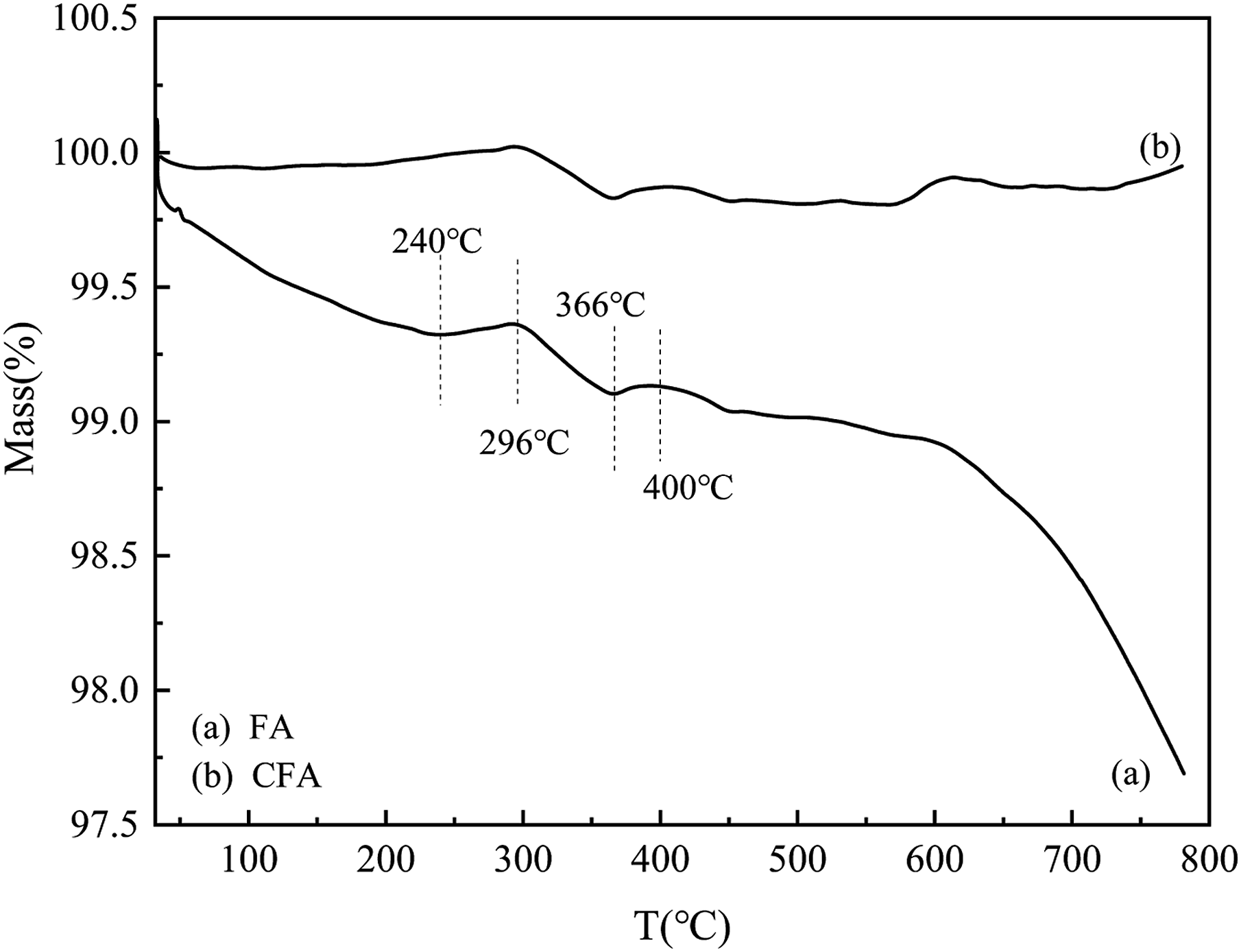
Figure 12 presented the TG-DTG curves of MH and CFA. In Figure 12(a), it can be observed that pure MH exhibited a weight loss rate of 4.38% in the temperature range of 50∼278°C. This weight loss was attributed to the evaporation of free water and crystal water presented on the surface of MH. Furthermore, between 278 and 423°C, the weight loss rate increased to 23.65%, indicating a faster weight loss due to the decomposition of MH into magnesium oxide. The theoretical weight loss rate of MH was 33.33%, and the decomposition process continued at temperatures ranging from 400 to 700°C. This was because, in the later stages of decomposition, as the temperature increased, the magnesium oxide crystal nuclei on the surface of MH gradually aggregated and grew, leading to an increase in the thickness of the magnesium oxide film. Consequently, this hindered the evaporation of generated water in MH, resulting in a slow decomposition process.
35
At a temperature of 700°C, the quality of the CPs remained almost unchanged and reached a stable constant weight. This indicated that the CPs had been almost completely transformed into relatively stable magnesium oxide powders. According to Figure 11(b), CP1 exhibited a weight loss rate of 7.81% within the temperature range of 40 to 225°C. This weight loss can be attributed to the evaporation of free water and crystalline water presented on the surface of CPs. Subsequently, at temperatures ranging from 225 to 576°C, the weight loss rate increased to 8.59%. Conversely, at temperatures between 600 and 700°C, the weight loss rate decreased to 1.62%. This variation can be attributed to the thermal decomposition of MCH, leading to the generation of magnesium oxide and carbon dioxide. Similarly, Figure 12(c) illustrated that CP2 experienced a weight loss of 4.63% from 40 to 210°C due to the evaporation of free water and crystal water from its surface. Furthermore, the weight loss increased to 10.58% within the temperature range of 210 to 400°C, followed by a weight loss of 2.64% from 400 to 700°C. This weight loss was a result of the decomposition of MH into magnesium oxide, water, and a small amount of MCH, which further decomposed to generate magnesium oxide and carbon dioxide under heat. Finally, Figure 12(d) indicated that CP3 exhibited a weight loss rate of 5.75% within the temperature range of 40 to 237°C, which was caused by the evaporation of free water and crystal water on the surface of the CPs. At temperatures ranging from 237 to 595°C, the weight loss rate exhibited a significant decrease of 9.45%. This reduction can be attributed to the intricate decomposition process of MCH, resulting in the generation of magnesium oxide, carbon dioxide, and a minor quantity of MH breakdown into magnesium oxide and water. Additionally, intriguing insights from Figure 12(a) and (c) emphasize At temperatures ranging from 237 to 595°C, the weight loss rate exhibited a significant decrease of 9.45%. This reduction can be attributed to the intricate decomposition process of MCH, resulting in the generation of magnesium oxide, carbon dioxide, and a minor quantity of MH breakdown into magnesium oxide and water. Additionally, intriguing insights from Figure 12(a) and (c) emphasize that the introduction of MH on the surface of CFA induces an expedited pace of decomposition. TG-DTG curves of MH and CFA.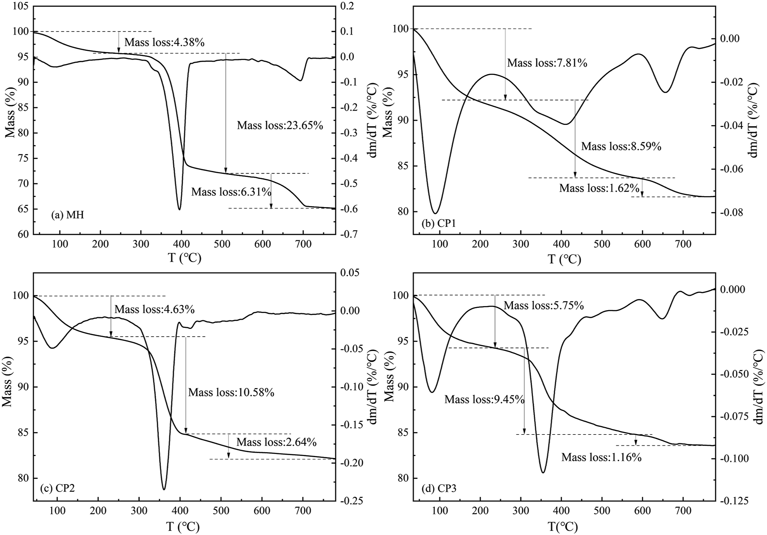
Upon heating, MCH underwent an initial heat absorption phase accompanied by the release of bound water. Subsequently, it underwent rapid decomposition at elevated temperatures, yielding active magnesium oxide and carbon dioxide. Remarkably, this decomposition process exhibited a unit heat absorption of 864 J g−1, thereby playing a pivotal role in endothermic cooling. The resulting active MgO demonstrated exceptional properties as a refractory material, capable of absorbing various substances, including radicals and carbon, when coated onto combustible surfaces. Consequently, it exhibited remarkable flame retardant and smoke suppression effects. Moreover, the CO2 released during the decomposition process acted as a potential extinguisher when carried by the PA6 substrate, forming an isolating layer around the combustion area. This effectively reduced air contact with the combustible materials, ultimately enhancing the oxygen index.
At 340°C, MH exhibited thermal decomposition, leading to the generation of active MgO and the release of a substantial amount of crystal water. Notably, this decomposition process was characterized by a unit heat absorption of 773 J g−1, thereby playing a crucial role in heat absorption and temperature reduction. Active MgO displayed exceptional capabilities to absorb a wide range of substances, including free radicals and carbon, thereby exerting notable flame retardant and smoke suppression effects. Simultaneously, the released crystal water also contributed to heat absorption, effectively lowering the surface temperature of PA6. The resulting water vapor further diluted the concentration of oxygen and combustible gases within the combustion zone, leading to a reduction in the burning rate.
36
Additionally, it is worth mentioning that nanoscale MH exhibited enhanced heat absorption compared to micron-level MH. This controlled the rate of temperature increase during PA6 combustion, ultimately contributing to an improved oxygen index.
37

Conclusion
(1) Three distinct types of FA-based composite materials with varying morphologies were successfully fabricated through the addition of different magnesium salts and sodium hydroxide. CP1 featured a surface coating of flaky MCH particles, CP2 exhibited a surface coating of spherical MH particles along with a small quantity of MCH particles, and CP3 displayed a surface coating comprising rod-shaped MCH particles and a minor amount of MH particles. (2) Upon the application of electrostatic forces and chemical bonding, CFA and surface nanoparticles underwent an attraction process, leading to the formation of a stable coating layer. It was important to note that the specific magnesium salt anions employed had varying effects on the surface energy and crystallization characteristics of the coating layer. As a consequence, distinct morphologies of the coating layer were observed, attributed to the influence of different magnesium salt anions. (3) The incorporation of the three types of composite powders in PA6 offered enhanced functionality, leading to improvements in the oxygen index and heat distortion temperature. PA6 filled with CP2, in particular, demonstrated the ability to initiate the silver-stripe effect upon material damage. This effect enhanced toughness, flame retardancy, heat distortion temperature, and overall processing performance. Furthermore, during the combustion process of PA6, the combination of CFA and the surface coating layer synergistically improved the oxygen index, further enhancing the flame retardant properties of the material.
Footnotes
Author contributions
HT contributed to Conceptualization, Methodology, Software, Validation, Formal analysis, Investigation, Data curation, Writing—original draft, Visualization. CL contributed to Conceptualization, Methodology, Formal analysis, Resources, Data curation, Visualization, Supervision, Funding acquisition. B contributed to Formal analysis, Writing—Review and Editing. GX contributed to Writing—Review and Editing. CX contributed to Writing—Review and Editing. SC contributed to Writing—Review and Editing. RQ contributed to Writing—Review and Editing.
Declaration of conflicting interests
The author(s) declared no potential conflicts of interest with respect to the research, authorship, and/or publication of this article.
Funding
The author(s) disclosed receipt of the following financial support for the research, authorship, and/or publication of this article: This work was supported by the National Natural Science Foundation of China (51804214).