
Abstract
The treatment of wastewater by adsorption is a good alternative technique and attracts extensive attention worldwide due to its versatility, scalability, and low operational costs. In this work, a Fe3O4 nanospheres/carbon core–shell structure is fabricated by combination of a template method and calcination. The morphology and crystal structure of the synthesized composite are characterized by transmission electron microscopy, X-ray powder diffraction, Fourier transform infrared spectrometer, and from nitrogen adsorption–desorption isotherms, confirming that the carbon layer with a porous structure is successfully loaded onto the surface of the face-centered cubic Fe3O4 nanospheres to form a core–shell structure. The adsorption performance of the Fe3O4 nanospheres/carbon core–shell structure is investigated by studying the effects of the initial pH value of the solution, the contact time, the initial concentration of the pollutants, the adsorption temperature, and the amount of adsorbent. The Fe3O4 nanospheres/carbon core–shell structure effectively removes heavy metal Chromium(VI) and a reactive light yellow dye. The results of batch experiments show that the removal efficiencies of heavy metal Chromium(VI) and the reactive light yellow dye are close to 100% under optimized conditions. The good adsorption performance of the Fe3O4 nanospheres/carbon core–shell structure toward various types of pollutants suggests a potential application in wastewater treatment.
Introduction
With an increasing world population and rapid industrial development, environmental pollution has become a serious problem, which seriously restricts the development of social economy and people’s healthy life.1–3 At present, water resources are being polluted more and more seriously due to the discharge of large qualities of inorganic and organic pollutants.4–6 According to the Ministry of Land and Resources of China, 90% of shallow groundwater in China has been polluted, and the most common pollutants include heavy metals, organic dyes, and pesticides. 7 Chromium(VI) is one of the major industrial heavy metal contaminants that exists widely in soil and groundwater. Hexavalent chromium [Cr(VI)] has been listed as a priority controlled pollutant by many countries due to its high toxicity and carcinogenicity to humans and ecosystems. 8 The excessive discharge of colored wastewater containing considerable amounts of dyes emerging from textile industrial effluents has threatened people’s health and the ecological environment. 2 The removal of dyes is very important to alleviate environmental pollution.2,9,10 The effective removal of Cr(VI) and dyes is related to the sustainable development of the global human environment,11,12 and it is thus an important endeavor.
Many methods have been used to remove Cr(VI) and dyes from water, such as chemical precipitation, 13 ion-exchange, 14 ozonation, 15 electrochemical treatment, 16 membrane separation, 17 photocatalysis, 18 and adsorption. 19 Among them, adsorption, a process of transferring pollutants from a solution to the adsorbent surface, is a good method due to its versatility, scalability, and low operational costs. 20 At the same time, it is very important to develop new functional nanomaterials for the removal of various pollutants.21–23 Barad et al. 24 synthesized the magnetic nanoparticles maghemite, by the microemulsion method, as an adsorbent to effectively remove hexavalent chromium. Meanwhile, it was also found that magnetic Fe3O4 nanoparticles also had a certain adsorption capacity for dyes and heavy metals. Singh et al. 25 synthesized magnetic Fe3O4 nanoparticles (Fe3O4@GTPs NPs) coated with green tea polyphenols (GTPs) by the wet chemical method, which exhibited large adsorption capacity and fast adsorption rates for methylene blue dye in water. In addition, the adsorbent can be separated from the liquid medium through magnetism, which allows multiple recycling of the adsorbent. Iconaru et al. 26 synthesized new magnetic (Fe3O4) nanoparticles by the coprecipitation method for the adsorption of the heavy metals As and Cu in aqueous solution. It was found that these Fe3O4 nanoparticles had a certain ability to remove pollutants from water, and their adsorption capacity was increased by 69.5% compared with the industrially similar material.
Carbon materials are commercially applied as adsorbents in adsorption processes, because they are inexpensive and can be synthesized easily on large scale.27,28 Thus, an adsorbent consisting of carbon and magnetic materials has potential applications in wastewater treatment. 29 As a functional material, the Fe3O4 nanospheres/carbon core–shell structure displays potential applications in many fields such as adsorption and catalysis, due to the characteristics of high specific surface area, high stability, and surface permeability.30,31 At present, a large number of scholars have made relevant research on synthetic methods toward Fe3O4/C core–shell structure. Yao et al. 32 used polypyrrole as carbon precursor to prepare core–shell materials with a movable Fe3O4 core and carbon shell. They have good magnetism and large specific surface areas and are good metal catalyst supports. Shi et al. 33 synthesized Fe3O4 particles as magnetic cores by the solvothermal method, and have prepared carbon shells using glucose, phenolic resin, and soluble starch resin as carbon sources. Finally, the Fe3O4@C magnetic nanoparticles with diameters of 100–200 nm and carbon shells of 8–20 nm were obtained. Wu et al. 34 have prepared Fe3O4 nanospheres and Fe3O4@C core/shell nanocomposites by the solvothermal method, and electrochemical tests showed that the carbon layer could significantly reduce the loss of Fe3O4 and improve the reversibility of Fe3O4.
In this work, using magnetic nanospheres as templates and glucose as a carbon source, the Fe3O4 nanospheres supported carbon core–shell structure was successfully fabricated by combining the template method with N2 annealing. The carbon layer is evenly loaded on the surface of the face-centered cubic Fe3O4 nanospheres to construct the core–shell structure. At the same time, their adsorption properties of heavy metal Cr(VI) ions and reactive light yellow dyes were further studied. The Fe3O4 nanospheres/carbon core–shell structure can effectively remove inorganic and organic pollutants, indicating its potential application in wastewater treatment.
Results and discussion
Morphology and structure characterization
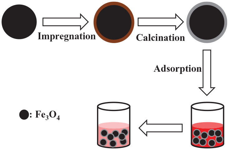
The formation of the Fe3O4 nanospheres/carbon core–shell structure is depicted in Scheme 1. The Fe3O4 nanospheres were prepared via simple hydrothermal conditions, and the carbon layer obtained by heat treatment under a nitrogen atmosphere promotes the existence of a large number of pores on the surface of the Fe3O4 nanospheres. Subsequently, the Fe3O4 nanospheres/carbon core–shell structure with the porous surface contributes to the adsorption of pollutants in wastewater.

Schematic illustration of the formation and adsorption of the Fe3O4 nanospheres/carbon core–shell structure.
Figure 1(a) shows the transmission electron microscope (TEM) image of the as-synthesized Fe3O4, and it is found that the diameter of the obtained spheres with the smooth surface was 200–300 nm. The Fe3O4 nanospheres/carbon core–shell sample has a diameter similar to that of Fe3O4 nanospheres, but the surface of the nanospheres is rough (Figure 1(b)). Based on the further observation of the inset in Figure 1(b), it was easily observed that a thin layer of about 10 nm coated the surface of the nanospheres to form the core–shell structure. It is possible to obtain a high specific surface area and increase the contact with pollutant molecules so as to improve the adsorption performance. As shown in Figure 1(c), the diffraction peaks of the prepared Fe3O4 at 18.2°, 30.1°, 35.5°, 37.0°, 43.1°, 53.4°, 56.9°, 62.5°, 74.0°, and 74.9° can be attributed to the (111), (220), (311), (222), (400), (422), (333), (440), (533), and (622) crystal planes of face-centered cubic Fe3O4 (JCPDS no. 82-1533). The core–shell sample displays a X-ray powder diffraction (XRD) pattern similar to that of Fe3O4, implying that the composite contains face-centered cubic Fe3O4. And no other peaks were observed in the XRD spectrum, indicating that other types of iron oxides were not detected in the composite. In addition, compared with the Fe3O4 nanospheres, before 20°, the baseline moves up due to the existence of carbon in the composite.
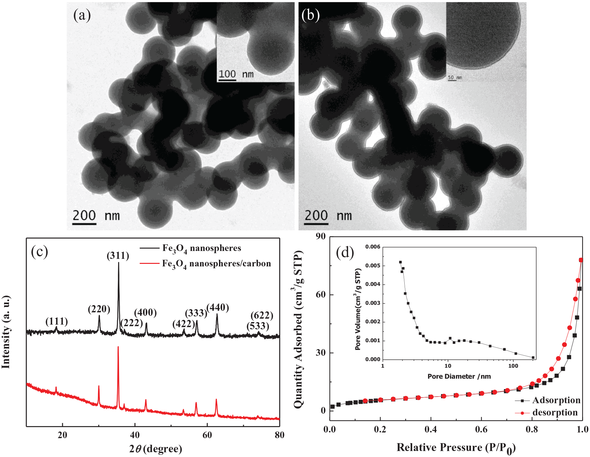
TEM images (a and b) and XRD spectra (c) of the Fe3O4 nanospheres (a) and the Fe3O4 nanospheres/carbon core–shell structure (b), and nitrogen adsorption–desorption isotherm (d) and pore size distribution (inset) of the Fe3O4 nanospheres/carbon core–shell structure.
The obtained Fe3O4 nanospheres/carbon core–shell structure was investigated from the nitrogen adsorption–desorption isotherms and pore size distribution. As shown in Figure 1(d), the Fe3O4 nanospheres/carbon composite with 21.02 m2 g−1 exhibits type IV isotherms with a hysteresis loop at P/P0 = 0.70–1, indicating the porous feature.35,36 The existence of a porous structure on the surface of the carbon shell was further verified by the pore size distribution based on the BJH model. 37 The pore diameter was measured as about 10.8 nm (inset of Figure 1(d)), which may be the result of heat treatment.
Figure 2(a) shows the high-resolution transmission electron microscopy (HRTEM) of the obtained composite. It was obviously observed that a thin layer coated on the surface of the nanospheres, which could be confirmed by the elemental mapping patterns of Fe and C elements (Figure 2(b) and (c)). The signal of Fe element was strong at the center and weak at the edge of the sphere, while the signal of C element at the edge of the sphere was not weaker than that at the center. This indicated that the iron element occupied the middle of the sphere to form a core and the carbon element was possibly distributed at the edge of the sphere to form a shell, thus constructing a core–shell structure. The above result was further proved by the elemental line profiles (Figure 2(d) and (e)). Moreover, the strong signal of C element at the edge of the spheres referring to the blue circle in Figure 2(e) indicated the carbon outer layer in the composite.

HRTEM image (a) of Fe3O4 nanospheres/carbon core–shell structure, elemental mapping patterns of (b) Fe and (c) C element in (a), and elemental line profiles of (d) Fe and (e) C elements referring to the yellow line in (a).
Figure 3 shows the Fourier transform infrared (FTIR) spectra of Fe3O4 nanospheres and Fe3O4 nanospheres/carbon core–shell structure. It was found that the large and broad absorption peaks at 3412 and 3406 cm−1 were assigned to the stretch region of the surface hydroxyl groups with hydrogen bonds and chemisorbed water.38–40 The absorption peaks at 1623 and 1614 cm−1 were related to O–H bending of molecularly physically adsorbed water.39,40 And the characteristic absorption peak at 580 cm−1 corresponded to Fe–O bond. 41 The strength of Fe–O bond in the Fe3O4 nanospheres/carbon core–shell structure was significantly weaker than that in the Fe3O4 nanospheres, indicating that the existence of the carbon outer layer on the surface of the Fe3O4 nanospheres affected the strength of Fe–O bond. This confirmed the existence of carbon in the core–shell structure. The presence of the characteristic peaks at 2356 and 1382 cm−1 attributed to the stretching vibrations of C=C 42 and C–O 36 was only observed in the composite, confirming that the carbon was successfully modified on the Fe3O4 nanospheres.
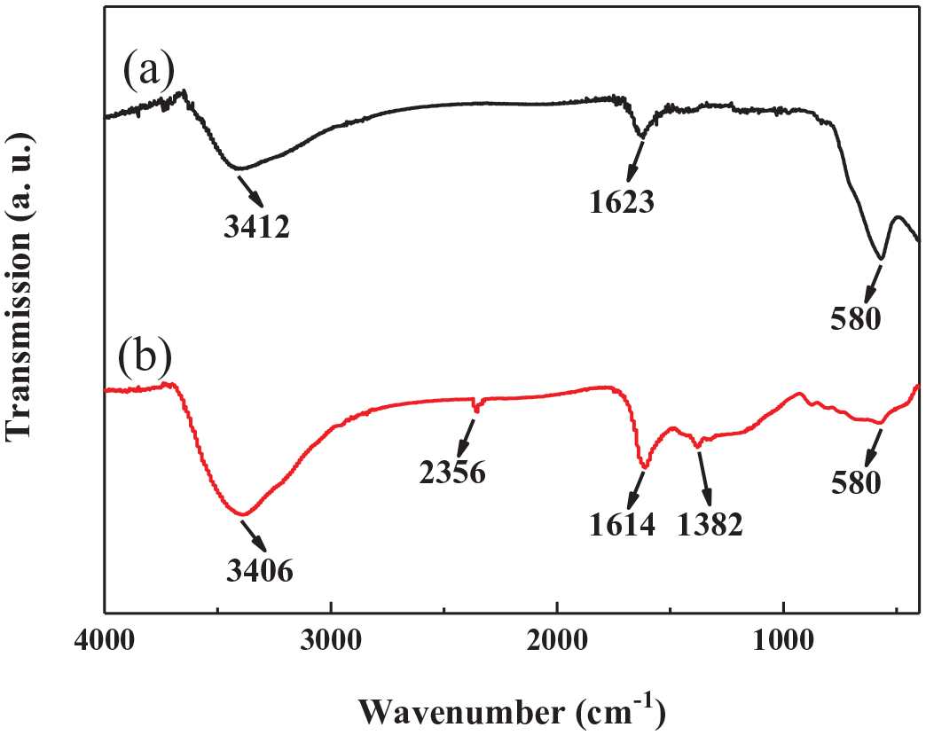
FTIR spectra of (a) the Fe3O4 nanospheres and (b) the Fe3O4 nanospheres/carbon core–shell structure.
Adsorption performance of heavy metal chromium
Effect of the initial pH value on Cr(VI) removal
The initial pH value has an important role in investigating the adsorption performance.43–45 The pH value of the chromium solution was adjusted with 0.1 mol L−1 of HCl solution or 0.1 mol L−1 of NaOH solution. It can be seen from Figure 4 that the removal rate of Cr(VI) over the Fe3O4 nanospheres/carbon core–shell structure increases first and then decreases with an increase in the initial pH value from 1.5 to 8.0, indicating that the Cr(VI) removal is highly related to the initial solution pH valve. When the initial pH value is 2.0, the removal rate of Cr(VI) is 88%, reaching a maximum. At pH = 8.0, only 0.38% of Cr(VI) is removed. Therefore, the optimum initial pH value of the chromium solution is 2.0. The strong adsorption of Cr(VI) ions at pH = 2.0 over the Fe3O4 nanospheres/carbon core–shell structure is mainly related to a change of the form of chromium in solutions with different pH values.46–48 When pH value is more than 6.8, Cr(VI) in solution exists in the form of CrO42−; when pH value is from 2.0 to 6.8, Cr2O72− and HCrO4− exists in solution; when pH value is less than 2.0, H2CrO4 exists in solution.46–48 The Cr(VI) ions are dissolved in solution as electronegative ions, while the Fe3O4 nanospheres/carbon core–shell structure is positively charged under acidic conditions, which significantly improves its ability to remove Cr(VI).46,47 With an increase in the initial pH value of the chromium solution, the functional groups containing Fe and O are deprotonated and the hydrophilicity is increased. Moreover, deprotonation at higher pH values makes the Fe3O4 nanospheres/carbon core–shell structure rapidly change into negative ions, which leads to the electrostatic repulsion between the negative Cr(VI) ions and adsorbents, and finally weakens the removal efficiency of Cr(VI). 49 In addition, the electrostatic attraction is more likely to be carried out under acidic conditions, which helps to effectively adsorb Cr(VI) at the lower pH value.50,51 When the initial pH value is 1.5, the removal rate of Cr(VI) decreases slightly, which may be caused by the formation of H2CrO4.

(a) Adsorption of Cr(VI) as a function of contact time at various initial pH values and (b) effect of the initial pH value on Cr(VI) removal.
Effect of the contact time on Cr(VI) removal
The adsorption behavior of Cr(VI) was affected by contact time. 44 As shown in Figure 5, at the beginning of adsorption, the adsorption capacity increases significantly with an increase in the contact time over 0–120 min, and reaches a maximum of q = 10.0 mg g−1 at a contact time of 120 min. After 120 min, the adsorption capacity of the composite decreases slightly and tends to equilibrium, which is nearly 10 mg g−1. This may be due to the shedding of Cr(VI) ions, resulting in a decrease in the adsorption capacity of the composite after 120 min, so a contact time of 120 min is the best.

Effect of contact time on Cr(VI) removal over the Fe3O4 nanospheres/carbon core–shell structure.
Effect of the initial concentration on Cr(VI) removal
The effect of the initial concentration on Cr(VI) removal was further studied. 44 When other conditions remained unchanged, a Cr(VI) ion solution with an initial concentration of 5–300 mg L−1 was prepared to investigate the relationship between its adsorption capacity q and Ce/q at different initial concentrations. The results are shown in Figure 6. Figure 6(a) shows that with an increase in the initial concentration of the Cr(VI) solution, the adsorption capacity q increases and finally tends to equilibrium. At a low concentration, the Cr(VI) ions are easily adsorbed on the available surface of the adsorbent. With an increase in the initial concentration of Cr(VI), the surface-active sites of the adsorbent are gradually saturated and the contact probability between Cr(VI) and the adsorbent is reduced, which slows the adsorption of Cr(VI). When the initial concentration of Cr(VI) is 200 mg L−1, the adsorption tends to balance and q reaches a maximum value of 42.5 mg g−1.

(a) Effect of the initial concentration on Cr(VI) removal and (b) the Langmuir adsorption isotherm.
In order to achieve effective and rapid adsorption, an investigation of the adsorption kinetics was necessary. As shown in Figure 6(b), according to the fitting of the Langmuir model, the adsorption isotherm can be obtained as: Ce/q = 0.20441 + 0.02288Ce (R2 = 0.99741), from which it can be calculated: qm = 43.71 mg g−1 and K = 0.1119 L mg−1. The basic characteristics of the Langmuir model can be described by the immeasurable dispersion constant RL = (1 + KC0)−1, where RL is also known as the equilibrium parameter, C0 is the initial concentration (mg L−1), and K is the Langmuir constant related to the energy of adsorption (L mg−1). The calculated RL values are between 0 and 1. Therefore, the adsorption test data are basically in accord with the Langmuir model, and the Langmuir equation is credible.
Effect of the adsorption temperature on Cr(VI) removal
The adsorption temperature also has an important effect on the removal of pollutants. 44 Figure 7(a) displays the relationship between the adsorption temperature and the adsorption capacity; the initial concentration of Cr(VI) solution was 150 mg L−1 and the adsorption temperature ranged from 298 to 333 K. It can be concluded that Cr(VI) removal over the Fe3O4 nanospheres/carbon core–shell structure increases on increasing the adsorption temperature. This may be due to the improved mobility of Cr(VI) ions driven by the sufficient energy to interact with the available active sites of the adsorbent molecules. 52 Therefore, a high adsorption temperature is helpful to improve Cr(VI) removal. The fitting equation is obtained by plotting ln(q/Ce)~1/T: ln(q/Ce) = −1126.6351/T + 2.64792 (R2 = 0.9789), as shown in Figure 7(b). According to the slope of the straight line −ΔH/R, the enthalpy change in the range of 298–333 K can be calculated as ΔH = 9.36 kJ mol−1, which indicates that the adsorption of Cr(VI) over the Fe3O4 nanospheres/carbon core–shell adsorbent is an endothermic process. Therefore, an increase in the adsorption temperature is beneficial to the adsorption.

(a) Effect of the adsorption temperature on Cr(VI) removal and (b) ln(q/Ce)~1/T curve.
Effect of the adsorbent dosage on Cr(VI) removal
The adsorbent mass is usually an important factor and is used to investigate the capacity of a solid adsorbent at a given initial concentration of adsorbate. 44 Under the optimal conditions, the relationship between adsorption dose and removal rate was studied with initial Cr(VI) concentrations of 5 and 15 mg L−1, respectively. As shown in Figure 8, the removal rate of Cr(VI) increases on increasing the adsorbent mass. When the initial concentration of Cr(VI) is 5 mg L−1, the removal rate of Cr(VI) increases rapidly when the adsorbent mass is less than 4 mg, reaching 96%, and then tends to 100% (Figure 8(a)). At a Cr(VI) initial concentration of 15 mg L−1, the removal rate of Cr(VI) goes up steadily with an increase in the adsorbent dosage, and gradually inclines to equilibrium at an adsorbent mass of 18 mg (Figure 8(b)). This is mainly attributed to an increase of the corresponding reactive sites due to an increase of adsorbents. With an increase in the initial concentration, more adsorbents are needed to provide more active sites in order to achieve a higher removal rate.
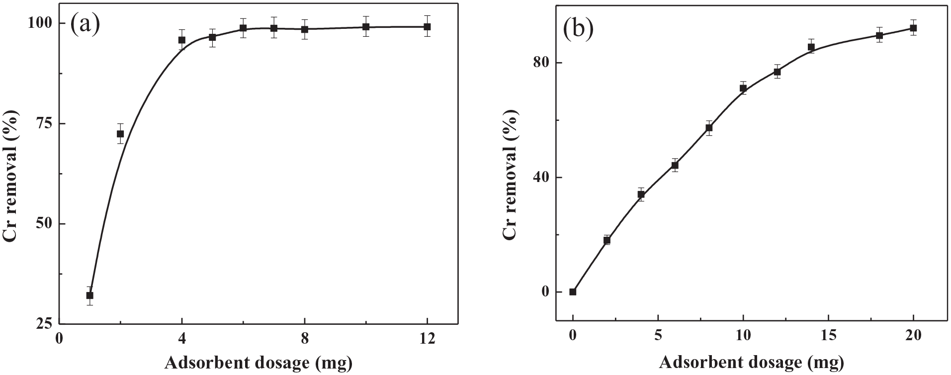
Effect of the adsorbent dosage on Cr(VI) removal with initial Cr(VI) concentrations of (a) 5 mg L−1 and (b) 15 mg L−1.
Adsorption performance of the reactive light yellow dye
Effect of initial pH value
Figure 9 shows the effect of the initial pH value on the removal efficiency of the reactive light yellow dye over the Fe3O4 nanospheres/carbon core–shell structure. A reactive light yellow solution with a dye concentration of 20 mg L−1 was prepared, and HCl solution (1.0 mol L−1) or NaOH solution (0.1 mol L−1) was used to adjust the pH value (0.5–8.0). It can be seen from Figure 9 that when the pH is less than 1.0, the reactive light yellow dye can be removed well, and the removal efficiency of the dye reaches up to 88% at pH = 1.0. Subsequently, the removal efficiency decreases gradually with an increase in the pH value. This may be attributed to the positive charge on the surface of the adsorbent caused by the acidic environment, leading to a maximum adsorption of anionic dyes. 53 At the same time, when the pH value is 0.5, the sulfonated groups in the dye molecule are easy to be protonated and exist in the form of –SO3H, which can make the level of dye removal slightly reduce. Therefore, the initial pH value of the dye solution has an effect on the removal of the dye. Considering the adsorption performance, the initial pH value of the dye solution is set at 1.0 in this experiment.
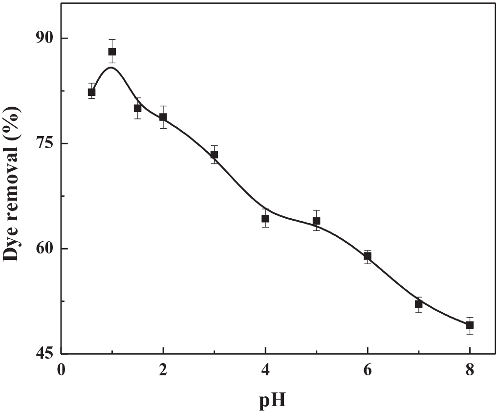
Effect of the initial pH on the removal of a reactive light yellow dye.
Effect of the contact time
The effect of the contact time on the removal of the reactive light yellow dye was investigated with an initial concentration of 15 mg L−1 at pH = 1.0. As shown in Figure 10, the reactive light yellow dye is hardly removed in the absence of adsorbent (red line in Figure 10). When the Fe3O4 nanospheres/carbon core–shell structure is used as the adsorbent, the removal efficiency of the dye shows a trend of increasing rapidly and then tending to be stable with an increase in the contact time, with 57% of the dye being removed over a contact time of 10 min, while the removal efficiency of the dye reaches a maximum value of 84% over a contact time of 120 min.

Effect of the contact time on removal of the reactive light yellow dye with (black) and without (red) the Fe3O4 nanospheres/carbon core–shell structure.
Effect of the initial concentration
The effect of the initial concentration of the reactive light yellow dye of 5–300 mg L−1 on the dye removal was also studied (Figure 11(a)). With an increase in the initial concentration of the reactive light yellow dye, the dye removal shows a trend of a rapid increase at first and then gradually becoming stable. The main reason is that the surface-active sites of the adsorbent are occupied by dye molecules little by little, which causes the adsorption to become slow. When the initial concentration of the dye is 250 mg L−1, the q-value reaches a maximum of 40 mg g−1. It is observed from Figure 11(b) that according to the fitting of the Langmuir model, the adsorption isotherm can be obtained from the equation Ce/q = 0.5436 + 0.0264Ce (R2 = 0.98742), and can be calculated: qm = 37.88 mg g−1 and K = 0.01435 L mg−1. The basic characteristics of the Langmuir model can be described by the infinite dispersion constant RL = (1 + C0)−1. The RL values are between 0 and 1. Therefore, the obtained adsorption data basically conform to the Langmuir model, and the obtained Langmuir equation is credible.

(a) Effect of the initial concentration on removal of the reactive light yellow dye and (b) the Langmuir adsorption isotherm.
Effect of the adsorption temperature
Figure 12 shows the effect of the adsorption temperature on the removal of the reactive light yellow dye over the Fe3O4 nanospheres/carbon core–shell structure with a concentration of 15 mg L−1 and an adsorption temperature range of 298–333 K. From Figure 12(a), it can be seen that the reactive light yellow dye is continuously removed with an increase in the adsorption temperature due to the enhanced mobility of the dye from the sufficient energy at the higher temperature. On the basis of the ln(q/Ce)~1/T curve (Figure 12(b)), the fitting equation is obtained: ln(q/Ce) = −752.19/T + 3.46645 (R2 = 0.9870). According to the slope of the straight line −ΔH/R, the enthalpy changes in the range of 298–333 K can be calculated as ΔH = 6.25 kJ mol−1, which indicates that the adsorption of the reactive light yellow dye is an endothermic process. Therefore, a high temperature is beneficial to the adsorption. In addition, the removal rate changes little in the range of 298–333 K. Therefore, the adsorption temperature is kept at 298 K from an economic point of view.

(a) Effect of the adsorption temperature on removal of the reactive light yellow dye and (b) the ln(q/Ce)~1/T curve.
Effect of the adsorbent dosage
The effect of the adsorbent dosage on the removal of the reactive light yellow dye with an initial concentration of 15 mg L−1 over the Fe3O4 nanospheres/carbon core–shell structure is investigated in Figure 13. As shown in Figure 13(a), the removal of dye is initially rapid and then slow, and gradually tends to balance. With an adsorbent amount of 10 mg, about 90% of the dye can be removed. When the amount is more than 15 mg, the removal of the dye is close to 100%. This may be due to an increase of adsorbed active sites from the increase of the adsorbent mass. Moreover, it is observed from Figure 13(b) that the adsorption capacity gradually decreases with an increase in the adsorbent dosage, which may be because the increase in dye removal is less than that of the adsorbent dosage. When the adsorbent mass is 20 mg, the adsorption capacity is 38.5 mg g−1.

Effect of the adsorbent dosage on the removal (a) and adsorption capacity (b) of the reactive light yellow dye.
Effect of the adsorption on the composite
Based on the TEM observation of the Fe3O4 nanospheres/core–shell structure after the Cr adsorption and dye adsorption, it is found that the used samples are still composed of a large amount of nanospheres. The thin carbon layer can be obviously observed by the enlarged image (insets in Figure 14(a) and (b)). This suggests that the adsorption of the Cr and the reactive light yellow dye will not destroy the core–shell structure consisting of Fe3O4 nanospheres and carbon. And the XRD characterization was used to investigate the effect of the adsorption on the crystal structure. As shown in Figure14(c), the used composite has the XRD curves similar to the un-reacted sample, indicating the unchanged crystal structure. The above results prove that the core–shell structure is stable and will not be affected by the adsorption of the Cr and the reactive light yellow dye due to the protection of the carbon outer layer.
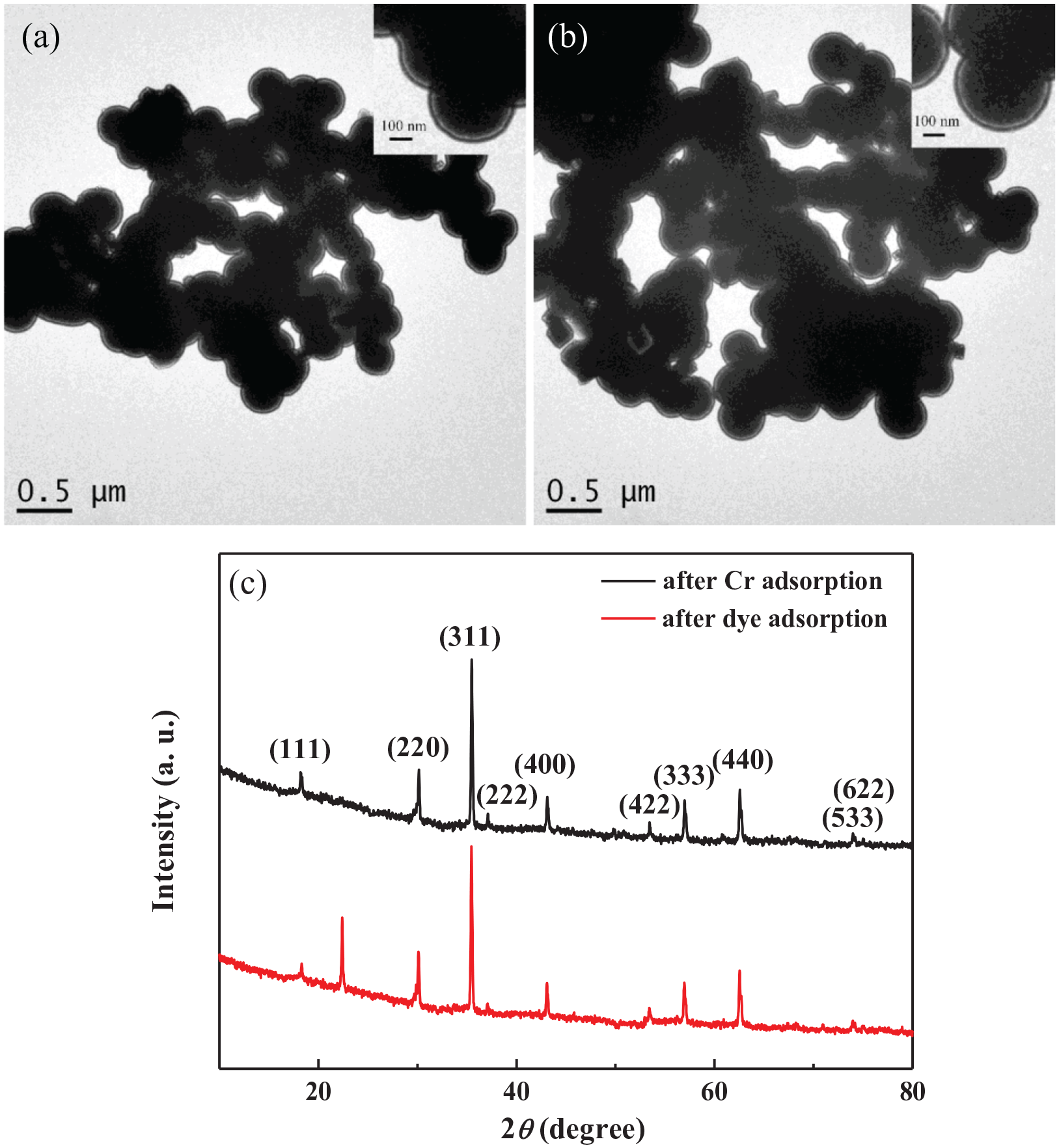
TEM images (a and b) and XRD spectra (c) of Fe3O4 nanospheres/carbon core–shell structure after the Cr adsorption (a) and the reactive light yellow dye adsorption (b).
Conclusion
In this paper, a Fe3O4 nanospheres/carbon core–shell composite was prepared by combination of the template method and the calcination method. The obtained magnetic Fe3O4 nanospheres/carbon core–shell structure was used as an adsorbent to remove the heavy metal chromium and a reactive light yellow dye. The optimum conditions for the adsorption behavior over the Fe3O4 nanospheres/carbon core–shell structure were determined by investigating the effects of the initial pH value, the initial concentration of the pollutants, the contact time, the adsorption temperature, and the adsorbent dosage. The main conclusions are as follows:
TEM shows that the synthesized composite is a core–shell structure with a uniform sphere size of 200–300 nm, while XRD analysis indicates that the iron in the synthesized composite is attributed to face-centered cubic Fe3O4. The core–shell structure is confirmed by the elemental mapping patterns and elemental line profiles of Fe and C elements in the composite, and the FTIR spectra further prove that the carbon exists in the composite.
The best initial pH value for the adsorption of the heavy metal chromium is 2.0 and the best contact time is 120 min. C0 = 200 mg L−1 is the best concentration and q reaches a maximum value of 42.5 mg L−1. The removal of Cr(VI) by the adsorbent is an endothermic process as ΔH = 9.36 kJ mol−1, and an increasing temperature is conducive to the adsorption.
The optimum pH value for the reactive light yellow dye is 1.0 and the optimum contact time is 120 min. When C0 = 250 mg L−1, the adsorption capacity tends to balance and q reaches a maximum value of 40 mgL−1. Removal of the reactive light yellow dye by the adsorbent is an endothermic process as ΔH = 6.25 kJ mol−1 and an increasing temperature is conducive to the adsorption.
The Fe3O4 nanospheres/carbon core–shell structure has good adsorption properties and stability for heavy metal chromium and the reactive light yellow dye, and thus may have potential applications in the removal of inorganic and organic pollutants.
Experimental section
Preparation of Fe3O4 nanospheres
Five millimoles of FeCl3·6H2O were placed in a dry beaker containing 20 mL of ethylene glycol (EG), and the mixture was stirred until the solid powder was completely dissolved. Following the addition of 10 mmol of sodium acetate (NaOAc) and 0.4 g of polyethylene glycol 200 (PEG200), the above solution was vigorously stirred for 30 min. The obtained solution was then transferred to a Teflon-line stainless-steel autoclave, which was heated in 180 °C oven for 12 h. After completion of the reaction, the product was collected and washed with a large amount of distilled water at least five times. Finally, it was dried in an oven at 80 °C to obtain Fe3O4 nanospheres for synthesizing the Fe3O4 nanospheres/carbon core–shell composite structure.
Preparation of the Fe3O4 nanospheres/carbon core–shell structure
Under the action of ultrasound for 2 h, 50 mg of the Fe3O4 nanosphere template and 2.0 g of anhydrous glucose were dispersed in 10 mL of distilled water and 10 mL of absolute ethanol as the solvent. The obtained suspension was stirred at 30 °C for 10 h. Subsequently, after the suspension had been centrifuged and washed with distilled water, it was placed in an oven at 70 °C for 12 h to give a dry powder. Finally, the powder was placed in a tube furnace for annealing under a nitrogen atmosphere at 400 °C for 2 h with a heating rate of 1 °C min−1. The Fe3O4 nanospheres/carbon core–shell structure was obtained as a black magnetic product.
Characterization of the Fe3O4 nanospheres/carbon core–shell structure
The morphology and structure of the product were investigated using a TEM (JEM-1011, JEOL, Japan, acceleration voltage 80 kV), HRTEM (JEM-2100F, JEOL, Japan, acceleration voltage 200 kV), and an X-ray diffractometer (XRD-6000, Cu Kα λ = 0.15406 nm, BRUKER AXS, Germany). The Brunauer–Emmett–Teller (BET) surface area and porous structure were measured by nitrogen adsorption–desorption isotherms on an Empyrean apparatus (Micromeritics, USA). The FTIR spectra were recorded using a VERTEX 70 FTIR spectrometer (NEXUS, USA).
Adsorption performance of heavy metal Cr(VI)
0.2 mg mL−1 of chromium ion solution was diluted to 1 μg mL−1 chromium standard solution. Different volumes of the chromium standard solution were mixed with 1.5 mL of 0.4 g L−1 diphenyl carbazide solution in standard colorimetric tubes. The resulting solution was tested for absorbance at 540 nm using a UV-Vis diffuse reflectance spectrometer (UV-2550, Shimadzu, Japan). According to the relationship between the absorbance value of the absorption peak at 540 nm and the chromium concentration (equation (1)), the concentration of chromium in the solution to be measured can be obtained

where A0 and A are the absorbance of the solution before and after the adsorption, respectively.
Anhydrous potassium dichromate (K2Cr2O7) as a chromium source was used to prepare the chromium solution with a concentration of 0.1–300 mg L−1. 0.1 mol L−1 of HCl solution and 0.1 mol L−1 of NaOH solution were used to adjust the pH value (1.5–8.0) of the chromium solution. Eight milligrams of adsorbent were added to 8 mL of the chromium solution at an adsorption temperature of 298–333 K. The suspension was oscillated for 2 h at a speed of 200 r min−1 and then centrifuged. The obtained supernatant was mixed with 1.5 mL of 0.4 g L−1 diphenyl carbazide solution in the standard colorimetric tubes for the UV spectrophotometric characterization. Based on equation (1), the adsorption capacity can be calculated and the adsorption isotherm can be drawn. According to the fitting of the Langmuir model, the adsorption capacity and equilibrium constant can be calculated as equations (2) and (3)

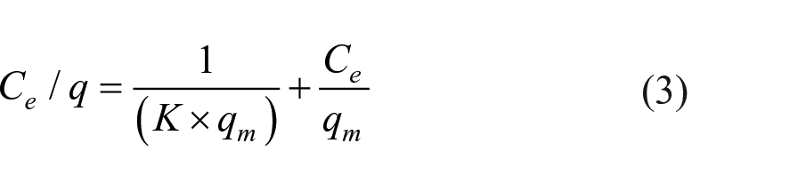
where q is the adsorption capacity per mass of adsorbate at equilibrium (mg g−1); C0 is the initial concentration of the pollutant (mg L−1); Ce is the concentration of the pollutant at the adsorption equilibrium (mg L−1); V is the volume of the adsorption solution (mL); m is the amount of adsorbent (g); qm is the maximum Langmuir adsorption capacity (mg g−1); K is the Langmuir adsorption constant (L mg−1).
Adsorption performance of reactive light yellow dye
The reactive light yellow dye is cibacron brilliant yellow 3G-P (C25H19Cl3N9NaO10S3, CAS number 50662-99-2, Sigma-Aldrich, St. Louis, MO, USA), which is used as the model to study the adsorption performance of the Fe3O4 nanospheres/carbon core–shell structure. Its chemical structural formula is shown in Scheme 2. A reactive light yellow solution with a concentration of 5–300 mg L−1 was adjusted to a pH value of 0.5–8.0 using 1.0 mol L−1 of HCl solution and 0.1 mol L−1 of NaOH solution. Eight milligrams of the adsorbent were added to 8 mL of the reactive light yellow solution, and the mixture was shaken for 2 h at a rate of 200 r min−1. The suspension was centrifuged and the obtained supernatant was analyzed by UV spectrophotometric characterization (UV-2550, Shimadzu, Japan). According to the fitting of the Langmuir model, the adsorption capacity and equilibrium constant can be calculated from equations (2) and (3).

Chemical structural formula of cibacron brilliant yellow 3G-P.
Footnotes
Acknowledgements
The authors thank Yan Jiayao from the School of Chemistry and Chemical Engineering, Shaoxing University for the help in the process of microtesting.
Author contributions
All authors contributed to the study conception and design. Conceptualization and investigation were performed by F.T. The formal analysis of the manuscript was completed by H.T. The original draft of the manuscript was written by B.L. and Y.W. The review and editing of the manuscript were completed by W.W. All authors have read and approved the final manuscript.
Declaration of conflicting interests
The author(s) declared no potential conflicts of interest with respect to the research, authorship, and/or publication of this article.
Funding
The author(s) disclosed receipt of the following financial support for the research, authorship, and/or publication of this article: This research was funded by the National Natural Science Foundation of China (41772311) and the National Natural Science Foundation of China (52179107).
Data availability
The data used to support the findings of this study are included within the article.