
Abstract
The variation of temperature fields during the winding process of CFRP (Carbon Fiber Reinforced Polymer) due to fiber winding is a key factor influencing its curing and shaping. Traditional heating methods result in energy wastage and environmental pollution during the heating process. Electromagnetic induction technology, as a non-contact, pollution-free, and efficient heating method, is playing an increasingly significant role in the process of heating and curing CFRP. This study focuses on two heating methods, internal and external, for CFRP wound circular tubes. It establishes finite element analysis models for induction heating with different coil structures. The heating mechanisms of different coil-induced CFRP wound circular tube models are explained, and the effects of external arc-shaped coils and external/internal annular coils on the temperature field distribution of CFRP wound circular tubes are investigated. By comparing simulations with experiments, the correctness of the numerical analysis model in this study is demonstrated. It offers viable heating methods for different conditions in industrial production, providing theoretical support and empirical data for the induction heating of CFRP wound circular tubes.
Keywords
Introduction
Lightweight materials and efficient production methods are the foundation for achieving sustainable development. Carbon Fiber Reinforced Polymer (CFRP) finds wide applications in aerospace, automotive manufacturing, civilian sports equipment, among other fields.1–5 This is attributed to its high strength and stiffness relative to its weight. Additionally, it offers heat and corrosion resistance, a low coefficient of expansion, and the capability to design and produce complex geometric shapes with customized features. It is widely recognized as a highly promising lightweight composite material for various applications. The filament winding process, a highly mechanized composite manufacturing technology, is extensively used in the forming process of CFRP. However, in the curing and shaping of Thermosetting CFRP through filament winding, temperature distribution becomes a critical factor influencing the quality of the formed product. Thermal convection, a mainstream heating method, exhibits significant drawbacks.6–10 In this heating method, the surface of CFRP components initially heats up for solidification, followed by heat transfer within the component to achieve overall curing. This process leads to considerable heat loss and uneven solidification of the CFRP, thereby reducing the quality of the formed product. Finding a new heating method to replace the current mainstream heating technique has become a focal point in the research on heating and solidifying CFRP. Electromagnetic induction technology, widely used in welding and inspection fields, stands out for its high heating efficiency, non-contact heating, simple and user-friendly device setup, and eco-friendliness. The conductivity of carbon fibers allows for the application of electromagnetic induction heating technology in the heating and curing of CFRP components.11–15 As a result, scholars have conducted numerous studies on the mechanism and temperature distribution of electromagnetic induction heating in CFRP.16–19
Yarlagadda et al. 20 and their research on induction heating in CFRP processes discovered that three heating modes—resistance heating, capacitance heating, and impedance heating—are the reasons for CFRP's susceptibility to induction heating, with resistance heating being the primary influencing factor for heating effectiveness. Lundstrom et al., 21 in their study of woven CFRP, established a simplified finite element numerical model with unidirectional layers. They experimentally verified the electrical and thermal properties and applied them to numerical simulations, revealing that the temperature distribution closely matched the experimental results. Their research found that when the fiber volume fraction exceeds 50%, the simulation's maximum temperature closely matched the experimental test, with an error margin within a few percentage points. When the fiber volume fraction falls below 40%, the maximum temperature differed by only around 10%. Miller et al. 22 established a mechanism model for the varying influence of induced heating within the material due to factors such as fiber arrangement and volume fraction in CFRP, affecting carbon fiber content and interlayer fiber contact. Lundstrom et al. 23 proposed a numerical model applicable for inducing heat in CFRP flat plates, calculating temperature and power distribution in unidirectional fiber cross-ply CFRP plates based on this model. Fu et al. 24 provided a modeling approach considering the influence of material internal carbon fiber texture on temperature field distribution and variation laws. They analyzed the electromagnetic eddy current field's coupling distribution, heating process, and temperature distribution during induction heating using a finite element micro-model. The aforementioned scholars have analyzed the heating mechanisms and research methods for induction-heated CFRP woven flat panels. However, there seems to be a lack of analysis for wound structures of CFRP circular tubes. Therefore, this paper focuses on the induction heating study of CFRP wound circular tubes using both external and internal coil heating methods.
The temperature field variation in CFRP wound pipes is a crucial factor influencing the heating and forming process. In this paper, the focus is primarily on the analysis of the induction heating temperature field for thermosetting CFRP. This paper establishes a finite element analysis model based on the wound structure of CFRP cylindrical tubes, considering the multi-physics field coupling in induction heating. Two heating methods, internal and external, are studied for the induction heating of CFRP-wound cylindrical tubes. Through an external arc-shaped coil induction heating model, the paper illustrates the heating mechanism of the CFRP-wound cylindrical tubes. Additionally, by employing annular coils inside and outside the tube, the study investigates the impact of different heating methods on the temperature field distribution of CFRP-wound cylindrical tubes. It analyzes the mapping relationship between the coil structure and the temperature field. By comparing simulation results with experimental data, the paper verifies the accuracy and reliability of the finite element analysis models for the two induction heating methods. In the subsequent chapters, this paper provides introductions, analyses, and corresponding discussions on the mathematical model of electromagnetic induction heating, as well as the process and results of establishing the finite element model. The accuracy of the finite element simulation is validated through experiments.
Mathematical model of electromagnetic induction
Electromagnetic induction equation
The basic principle of induction heating is based on the phenomenon of electromagnetic induction, and Maxwell’s equations are the mathematical expressions describing universal laws of the macroscopic electromagnetic field, core of the electromagnetic theory and basis for analyzing and solving electromagnetic field problems. Maxwell’s system of equations consists of Ampere’s law of loops, Faraday’s law of electromagnetic induction, Gauss’ law of flux, and Gauss’ law, which collectively describe the macroscopic properties of electromagnetic field. Since Gauss’ law is not relevant to the induction heating problem within the frequency range used herein, the differential form of Maxwell’s system of equations was utilized. According to Ampere’s loop theorem, when alternating current passes through induction coil, an alternating magnetic field is generated around the coil (equation (1)). Since electromagnetic heating is a seemingly steady electromagnetic field problem, i.e., the field strength changes slowly enough with time to make the electromagnetic wavelength much larger than the geometry of the study area, the field strength at the observation point changed almost instantaneously with the electromagnetic field source. Therefore, the displacement current density (


Here,
From Ohm’s law, the induced electric field (from equation (2)) generates a vortex current in the closed loop. When J0 (A m−2) and σ (−) represent current density vector in heated material and conductivity tensor, respectively,

The calculation of heat generation
Heat conduction equation
During heating process of CFRP wound round tubes, the temperature distribution field is controlled by equation (6).

In the formula, ρ, C
p
, and
Boundary conditions
In the induction heating process, the surface of heated object exchanges heat with the surrounding environment after warming up, of which the most heat exchange is with space, so the convective heat flux of air needs to be considered, as shown in equation (7).

Here,
With the gradual increase in temperature, thermal radiation generated by the material needs to be considered, and the radiation intensity of the material surface is shown in equation (8).

Here, γ and ε represent Boltzmann constant and emissivity of the material surface, respectively.
Geometric modeling of two heating methods for heating CFRP wound round tubes
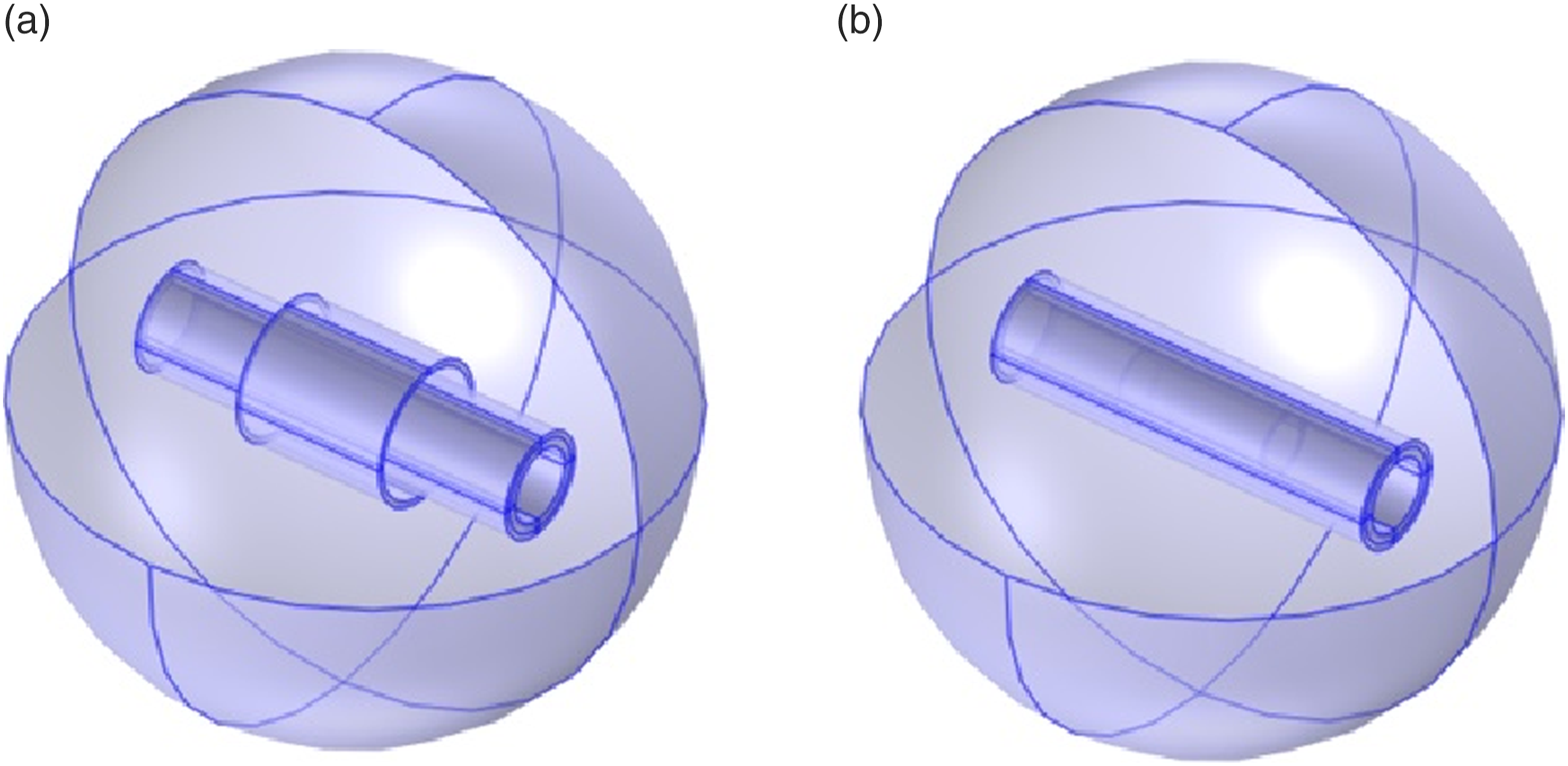
This study adopted the winding structure circular tube as the research object and COMSOL Multiphysics 5.4 finite element software to establish the external arc coil induction heating geometry model, external toroidal coil and built-in toroidal coil induction heating model, respectively, as shown in Figure 1, the geometric model for external arc coil induction heating is presented. Figure 1(a) provides an overall schematic of the geometric model for external arc coil induction heating. Figure 1(b) represents the front view of the geometric model, while Figure 1(c) displays the cross-sectional view of the geometric model. In the figures, models have been constructed for air, the coil, CFRP tubes, and fiberglass-reinforced plastic (FRP) mold. The electrical conductivity of fiberglass-reinforced plastic is set to 0, and its relative magnetic permeability is consistent with that of CFRP. This ensures that it has no impact on the heat generation and temperature field distribution. Therefore, fiberglass-reinforced plastic is chosen as the mold material to support CFRP for the induction heating study. Figure 2 illustrates the geometric models for both external and internal toroidal coil induction heating. In Figure 1, the CFRP wound circular tube being heated is rotating, whereas in Figure 2, the CFRP wound circular tube being heated remains stationary. Geometric model of external arc coil induction heating: (a) geometric model overall schematic diagram (b) front view of the geometric model (c) geometric model cross section. Geometric models of external and internal toroidal coil induction heating: (a) geometry diagram of external toroidal coil heating and (b) geometry diagram of internal toroidal coil heating.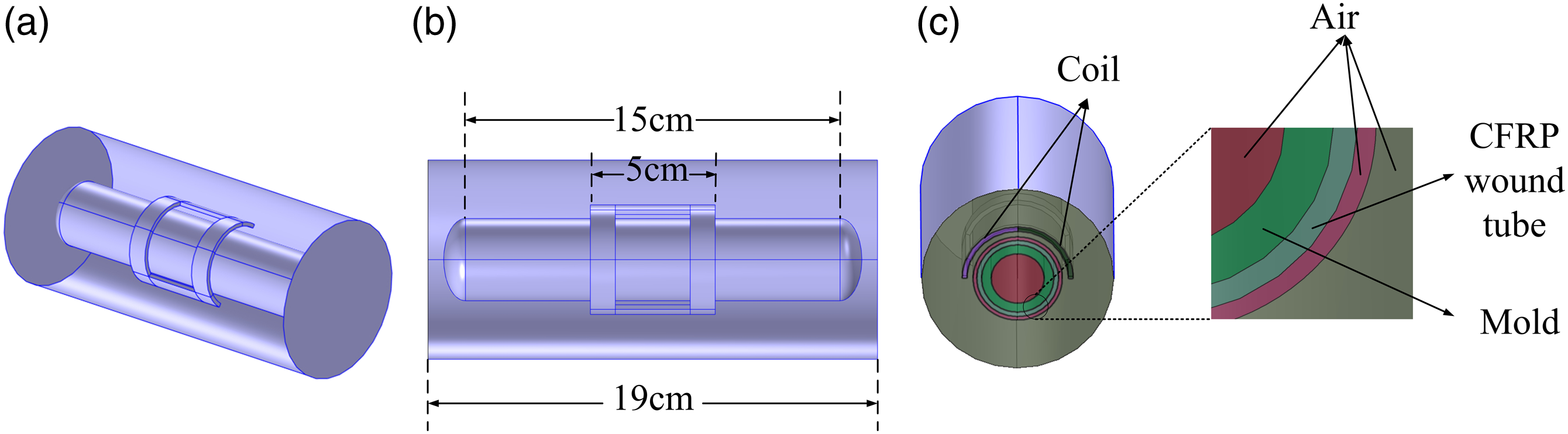
Geometric modeling
This study focuses on the establishment of the geometric model for induction heating of an external arc coil: firstly, the work plane was established, a sketch of the circular tube model was drawn, the work plane was repeatedly established to draw the bottle air domain including the circular tube, and they were merged to form a whole, retaining the internal boundary. Herein, a new work plane was created, coil outline was drawn, and a completely curved coil was formed by stretching, translating, and rotating. Create a cylindrical air domain that encloses the bottle air domain and the coil. To ensure the continuity of the magnetic field between the rotating CFRP wound circular tube in the external arc coil heating model and the stationary coil, and to achieve effective heating, the “Form Assembly” function can be used to enable relative motion between the coil component and the CFRP wound circular tube component, forming a consistent boundary at the interface between rotation and stationary. The specific steps are as follows: take the difference between the cylinder and the bottle air domain; perform a union operation between the difference and the coil to form a whole; apply the “Form Assembly” operation on the surface of the bottle air domain to create a consistent boundary. Figure 3 illustrates the concept of a consistent boundary, where the mixed yellow and pink region represents the consistent boundary. The external region represents the stationary component, while the internal region represents the moving component, allowing relative motion between the two components. Schematic diagram of consistent boundary pairs.
Setting of material parameters
The material parameters of the CFRP wound circular tube can be obtained through the mixture rule formula, Springer-Tsai model,
25
and calculations. The density of CFRP is:
In the equation,
The specific heat capacity of CFRP is:
In the equation,
The Springer-Tsai model can be used to calculate the thermal conductivity coefficient.
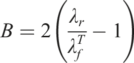
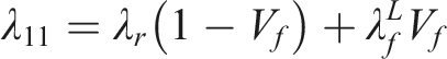
In the equation,
The inner diameter, thickness, and length of CFRP winding circular tube were 30, 2, and 150 mm. The length of the FRP mold is consistent with that of the CFRP tube, with a thickness of 3 mm and an inner diameter of 12 mm, respectively, and arc coil was set to cover half circumference of circular tube, i.e., bending arc of 180°, coil was parallel to circular tube axis length 50 mm, winding turns of 100 turns, external ambient temperature was set to 20°C, induction heating frequency was 13 kHz, current size was 16 A, coil and circular tube spacing was 4 mm, rotation speed of the circular tube was 7.5 r/min; the inner diameter of the built-in toroidal coil was 24 mm, inner diameter of the external toroidal coil was 38 mm, length was 50 mm, current size was 20 A, induction heating frequency was 30 kHz, distance between the coil axis and the circular tube axis was 0 mm, and the rest of the parameters were kept the same as the settings of the arc coil.
The winding structure had structural characteristics of fiber cross, bending, and lamination. In one winding cycle, the fiber belt being wound and the fiber belt already wound to the surface of the core mold cross each other, and the wound fiber belt produced the bending effect. However, in the next winding cycle, the fiber belt being wound meets the edge of the fiber belt of the previous cycle, and so on repeatedly spread over the entire surface of the core mold as a layer, and the layer repeatedly was the laminated structure. Figure 4 shows a Schematic diagram of winding mode, where Φ represents the winding angle, and the positive and negative signs denote directions Schematic diagram of winding mode.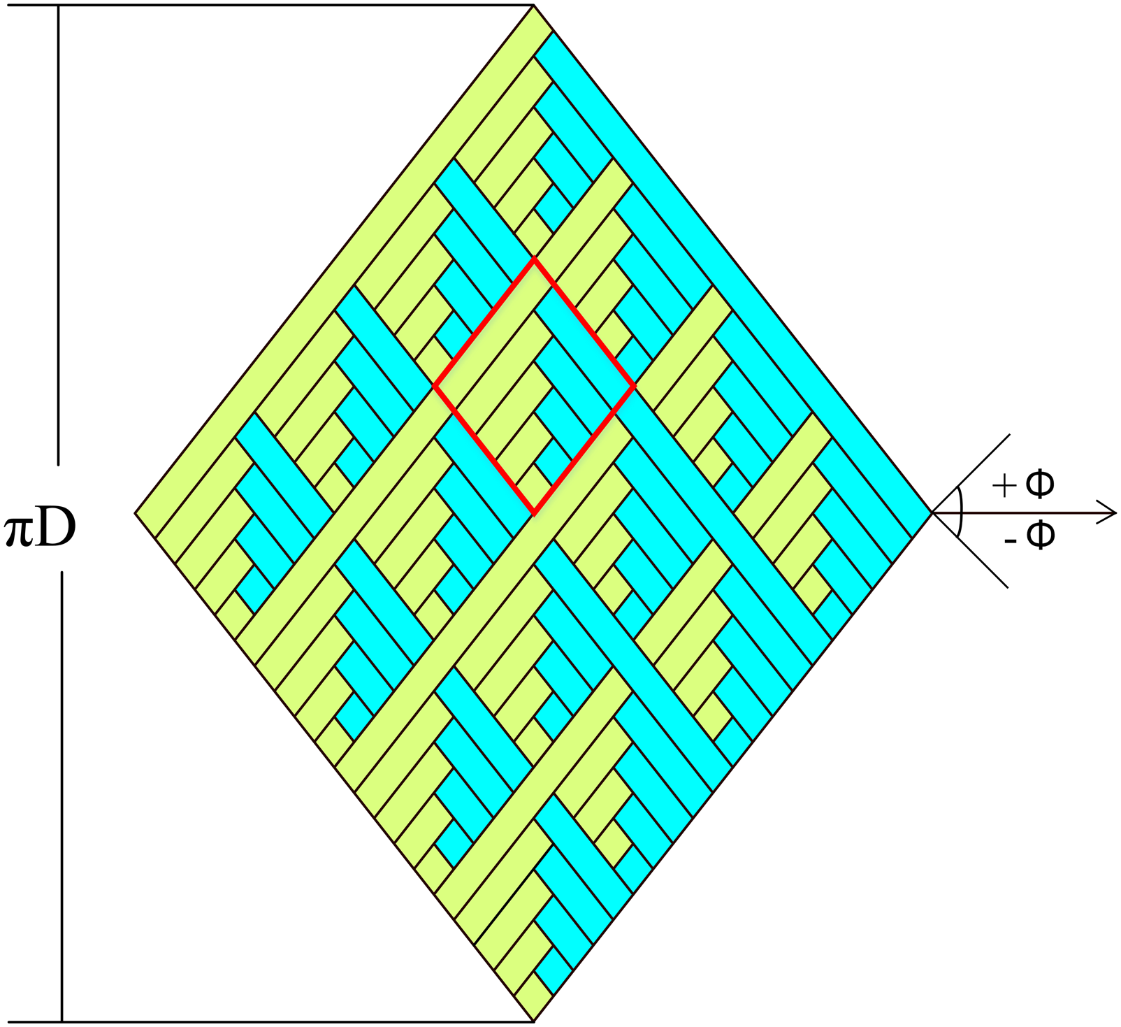
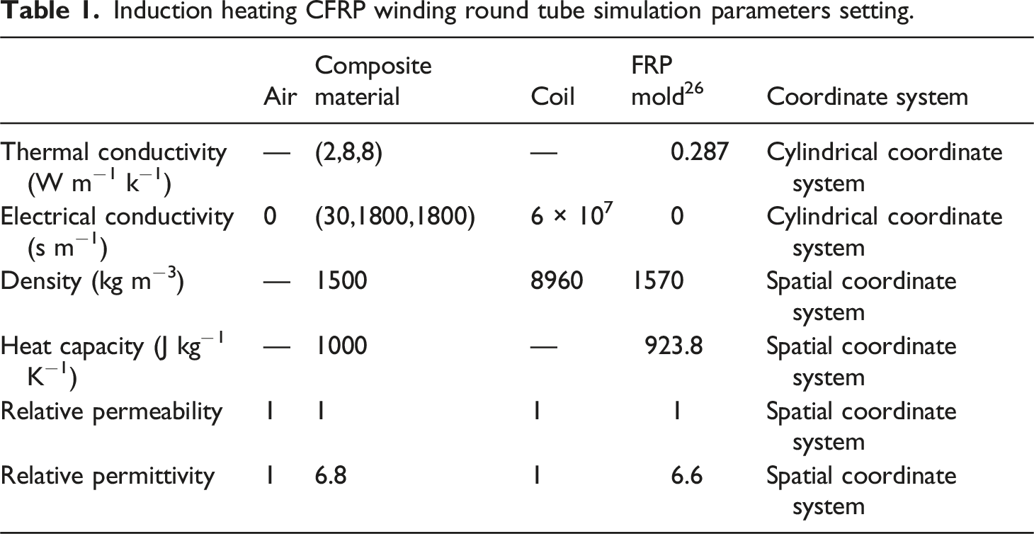
Induction heating CFRP winding round tube simulation parameters setting.
Division of the grid
In this paper, the geometric model of an external arc coil induction heating is used as an example for mesh generation. Due to the complexity of the model and the difficulty in calculating the coupled physical fields involved, it is necessary to follow an inside-to-outside sequence for mesh partitioning in order to improve computational efficiency and reduce the required resources within an acceptable accuracy range. Proper mesh partitioning is crucial for the geometric model. As this paper combines the electromagnetic coupling with mechanical rotation in a multiphysics field modeling using the moving mesh method, the compatibility of adjacent meshes at consistent boundaries directly affects the accuracy of the analysis. Incorrect mesh partitioning can result in non-converging or even infeasible model calculation results. Therefore, to ensure the calculation of the three-dimensional model after rotation, it is still necessary to partition mutually matching meshes at consistent boundaries.
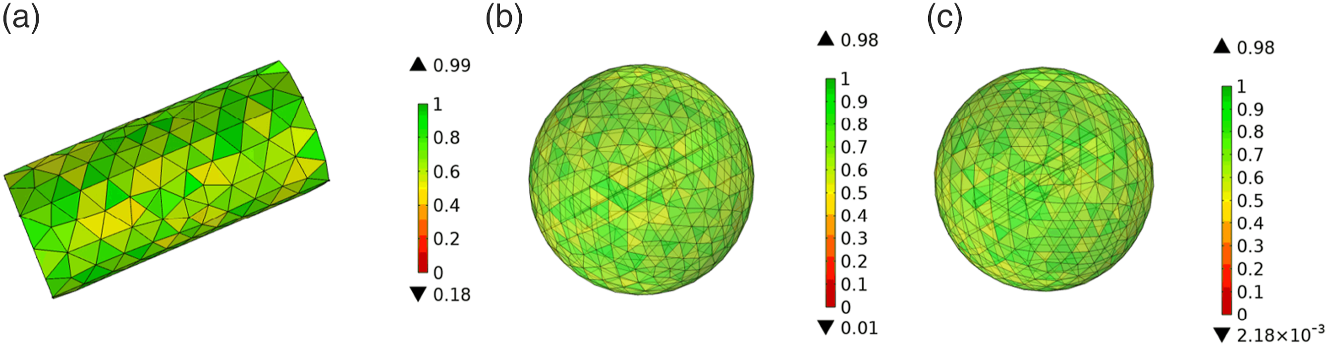
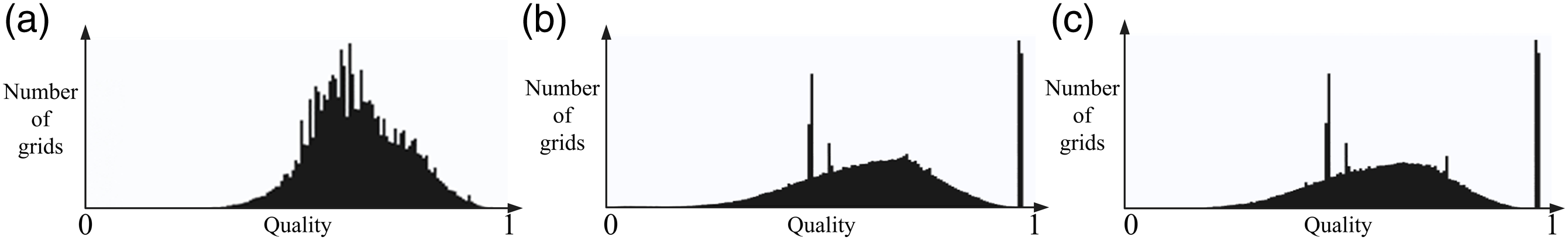
First, consistent boundary pairs are partitioned using a refinement method to improve the accuracy of the calculations. Next, the coil and circular tube are partitioned with a finer mesh. Finally, the air domain is partitioned with a coarser mesh. Figure 5 illustrates the mesh partitioning process, with the blue region representing the partitioned domains. Figure 6 displays the mesh quality plot, while Figure 7 shows the histogram of mesh quality. The horizontal axis in the graph represents grid quality scores, while the vertical axis represents the number of grids. From the figures, it can be observed that the mesh quality of model is concentrated mainly between 0.5 and 0.8. As the mesh quality value approaches 1, it indicates higher mesh quality in the partitioning. This demonstrates that the mesh quality of the models established in this paper is relatively good, enabling effective simulation of the actual heating process. Meshing process: (a) boundary pair meshing, (b) circular tube meshing, (c) coil meshing, and (d) air meshing. Grid quality diagram: (a) the mesh quality diagram for the arc-shaped coil induction heating; (b) the mesh quality diagram for external annular coil induction heating; (c) the mesh quality diagram for internal annular coil induction heating. Histogram of unit quality: (a) represents the histogram of mesh quality for arc-shaped coil induction heating; (b) demonstrates the histogram of mesh quality for external annular coil induction heating; (c) exhibits the histogram of mesh quality for internal annular coil induction heating.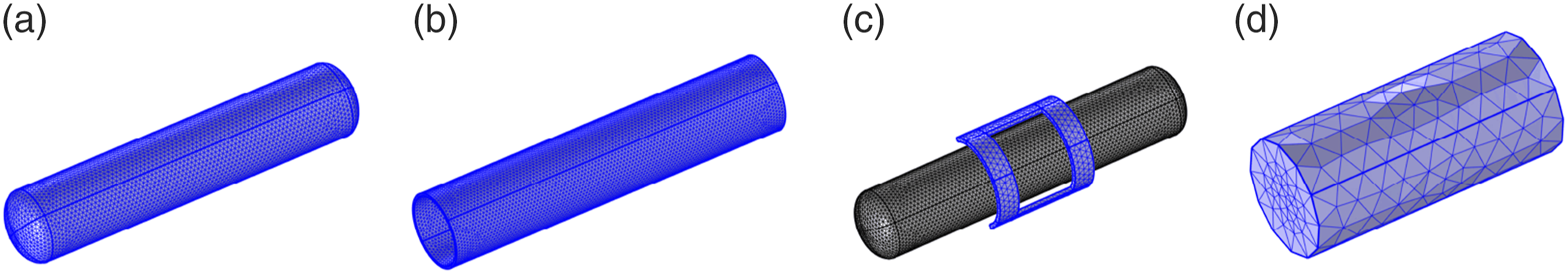
Analysis of electromagnetic induction heating mechanism of CFRP wound round pipe
Figure 8 shows the distribution of magnetic flux density generated by the electromagnetic coil in the CFRP wound circular tube. From the figure, it can be observed that the magnetic field is mainly concentrated in the region directly facing the coil, exhibiting a rectangular distribution. Additionally, the magnetic flux density is lower near the inner edge of the coil and farther away from the outer edge of the coil. Cloud map of the distribution of magnetic flux density in CFRP wound circular tube.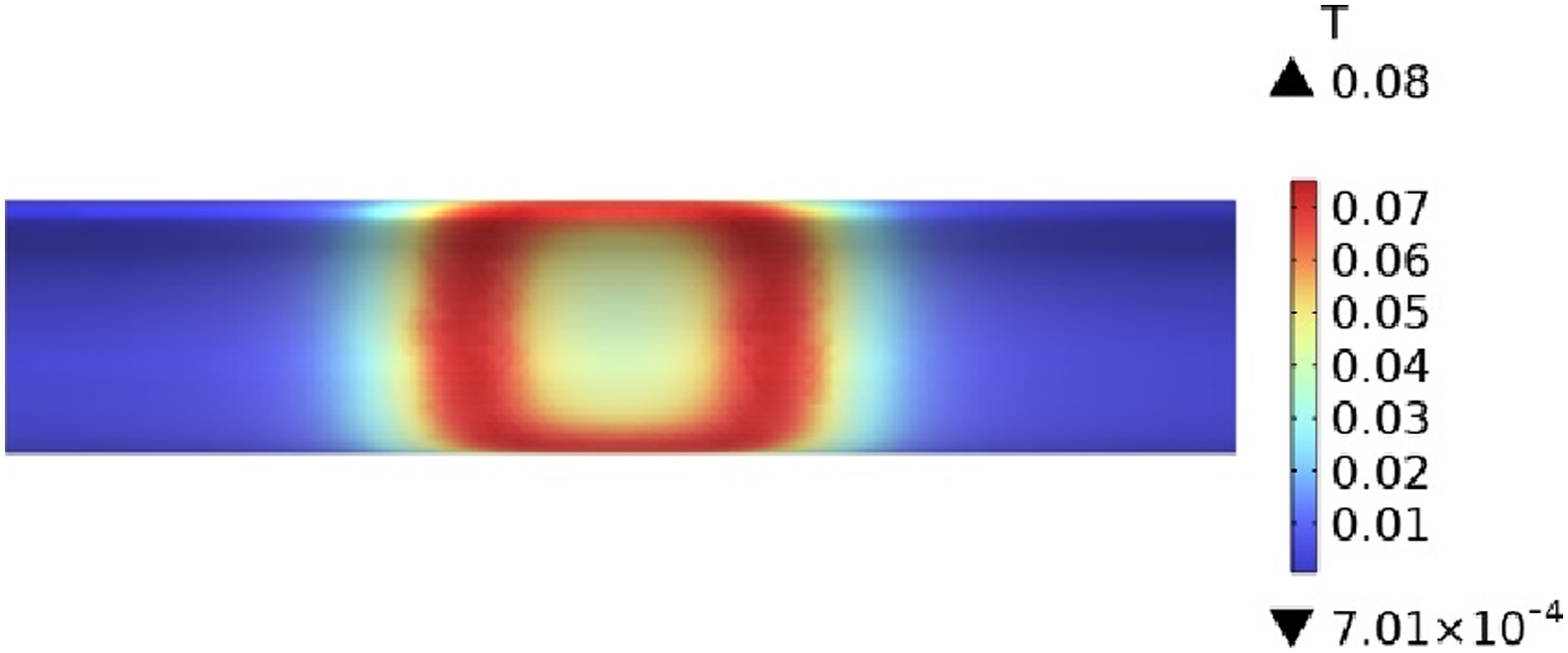
CFRP wound circular tube generates vortex eddy currents under the influence of an electric field. Figure 9 illustrates the cloud map of the flow direction and intensity distribution of vortex eddy currents in CFRP wound circular tubes. It can be observed from Figure 9 that the current distribution is concentrated in the central region between the two vertical edges of the coil. Furthermore, the distribution of the eddy current field remains almost consistent throughout the heating process from 15 s to 10 min. Cloud map of the distribution of eddy current field in CFRP wound circular tube. (a) Heating for 15 s (b) heating for 50 s (c) heating for 5 min (d) heating for 10 min.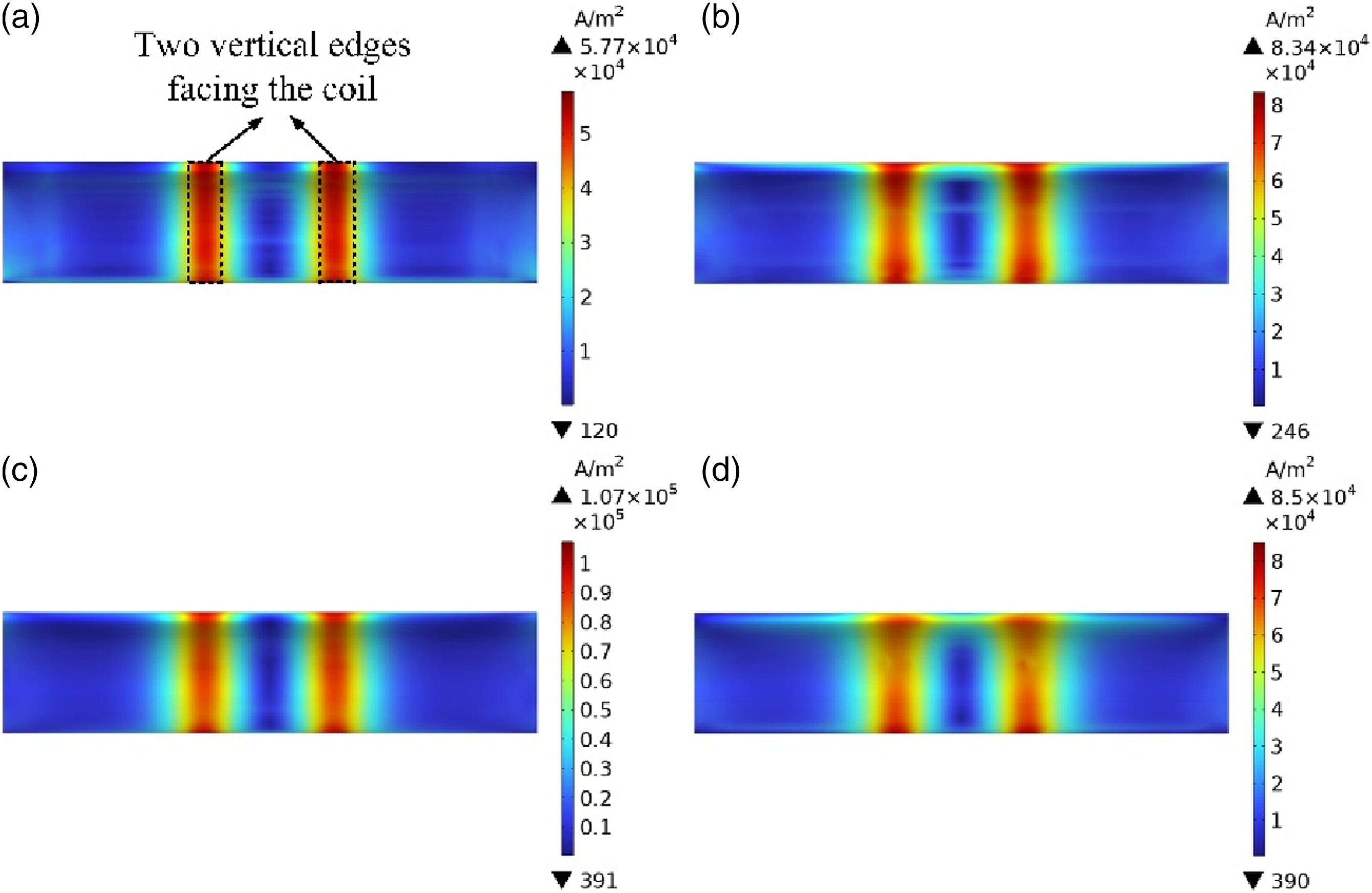
The vortex eddy currents generated in the CFRP wound circular tube, along with the resistance of the tube itself, produce Joule heating. Studying the heat generation in the wrapped tube is beneficial for understanding the temperature variation pattern of CFRP wound circular tubes. Figure 10 presents the cloud map of heat distribution in the CFRP wound circular tube. Under the influence of vortex eddy currents, the tube generates Joule heating, and therefore, the distribution of heat closely follows the distribution of vortex eddy currents. According to equation (4), the heat generation is directly proportional to the square of the current. Consequently, areas with high current density exhibit significantly higher heat generation, while regions with lower vortex eddy current density experience a noticeable decrease in heat generation. Cloud map of the distribution of heat generation in CFRP wound circular tube. (a) Heating for 15 s (b) heating for 50 s (c) heating for 5 min (d) heating for 10 min.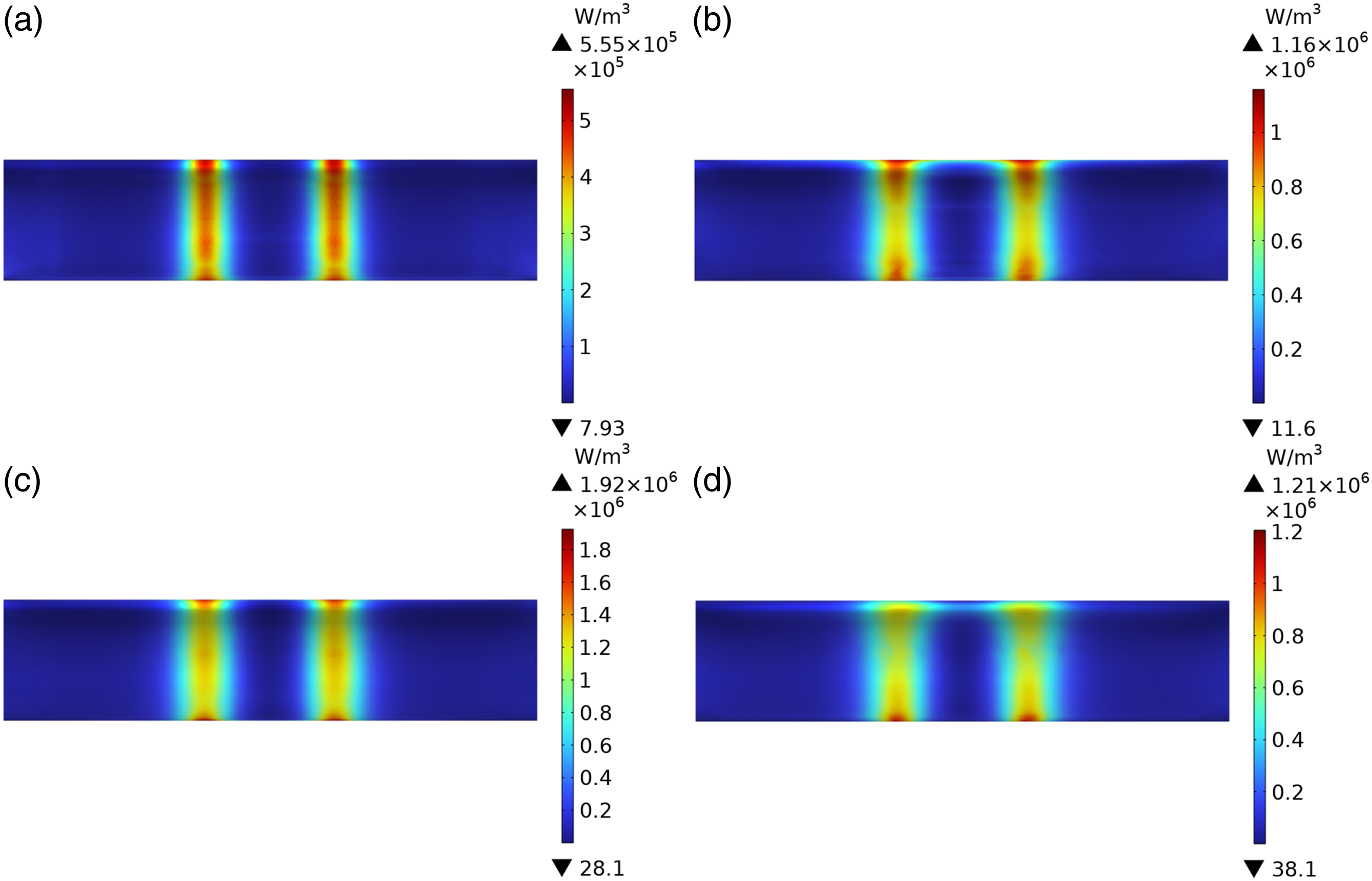
Figure 11 illustrates the temporal evolution of the temperature field distribution in the CFRP wound circular tube during external arc coil induction heating. From the figure, it can be observed that after heating for 15 s, the temperature field distribution is primarily concentrated in the region between the two vertical edges of the coil, with higher temperature values at these locations and gradually decreasing along the axis of the circular tube. At 50 s of heating, as the tube rotates, the temperature field expands, and the temperature in the central region of the coil increases. The highest temperature values still occur at the positions directly facing the two vertical edges of the coil. After heating for 5 min, the overall temperature increases significantly, and the temperature field distribution becomes more uniform in the central region, reaching a value of 141°C. After 10 min of heating, the temperature field exhibits a rectangular shape with a highly uniform distribution, and the temperature reaches 157°C. The highest temperature value in the upper trapezoidal region is 104.6°C. The temperature field distribution and diffusion trend can be correlated with Figure 10, where the heat generation is consistently concentrated in the region directly facing the two vertical edges of the coil. Therefore, this region experiences the highest temperature first and has the highest temperature values. With increasing heating time, the temperature field diffuses along the axis of the circular tube, eventually covering the entire region facing the coil. Cloud map of the temperature field distribution in CFRP wound circular tube heated by an external arc coil. (a) Heating for 15 s (b) heating for 50 s (c) heating for 5 min (d) heating for 10 min.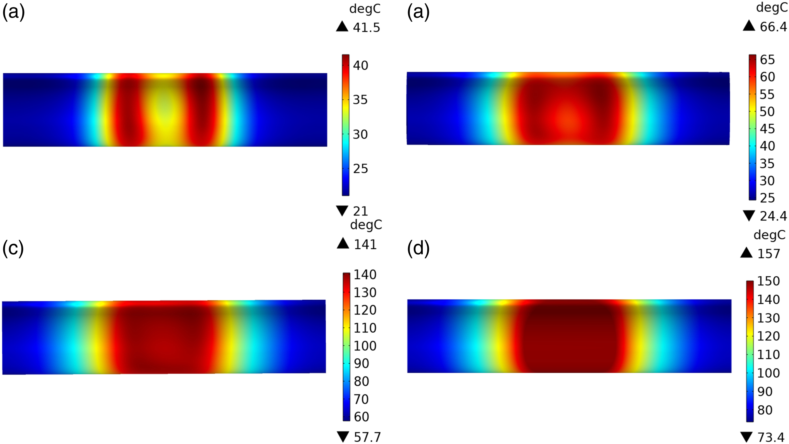
As shown in Figure 12, the cloud map illustrates the distribution of magnetic flux density in a CFRP wound circular tube heated by an external arc coil. Figure 12(a) represents the external arc coil, while Figure 12(b) depicts the internal arc coil. The following legends apply to both scenarios. From the figure, it can be observed that the magnetic flux density of both the external and internal arc coils primarily concentrates in the positions directly facing the coil. The center position of the external arc coil exhibits the highest density, while the two ends of the internal arc coil show the highest density. Furthermore, the magnetic flux density distribution of the internal arc coil is wider than that of the external one. Numerically, the external arc coil is larger than the internal one, indicating that it will generate larger currents in the circular tube. Cloud map of the distribution of magnetic flux density in a CFRP wound circular tube heated by toroidal coil. (a) Heating with an external toroidal coil. (b) Heating with an internal toroidal coil.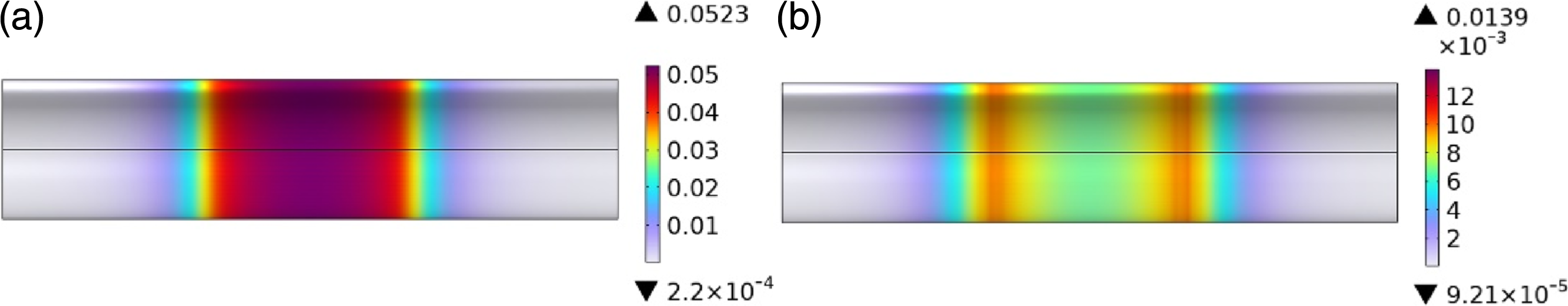
As shown in Figure 13, it illustrates the cloud map of the distribution of vortex eddy currents in a CFRP wound circular tube heated by toroidal coil. From the figure, it can be observed that the distribution of the vortex eddy currents appears rectangular and gradually spreads along the axis of the tube. In terms of numerical values, the maximum magnitude of vortex eddy currents generated by the external coil on the tube is one order of magnitude larger than that of the internal coil. This indicates that, under the condition of other variables being constant, using an external coil heating method can result in larger vortex eddy currents. This has significant implications for rapid heating applications. Cloud map of the vortex eddy current field in a CFRP wound circular tube heated by toroidal coil. (a) Heating with an external toroidal coil. (b) Heating with an internal toroidal coil.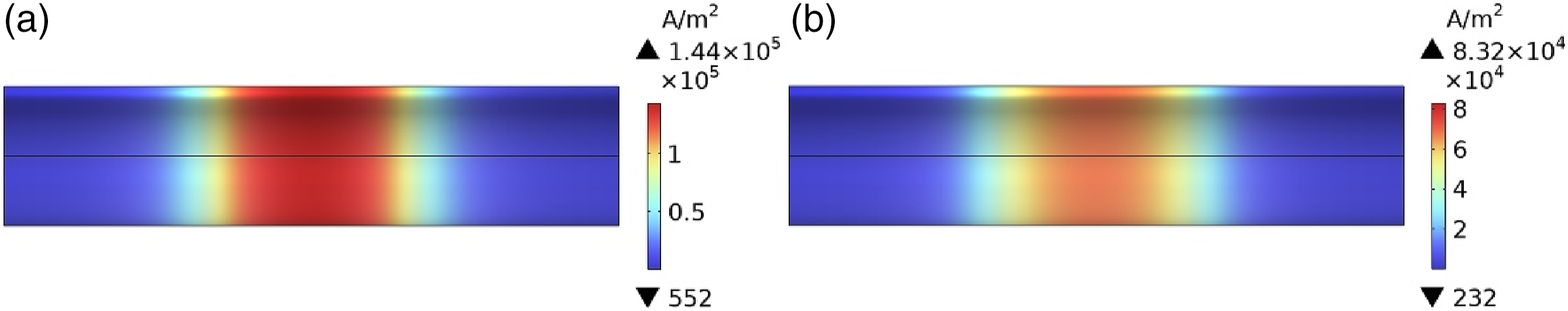
As shown in Figure 14, it illustrates the cloud map of the distribution of heat generation in a CFRP wound circular tube heated by toroidal coil. From the figure, it can be observed that the distribution of heat generation exhibits a rectangular pattern, which is highly similar to the distribution shown in Figure 13. Additionally, the heat generation values produced by the external coil heating method are significantly higher, providing validation for equation (4). Cloud map of the heat generation in a CFRP wound circular tube heated by toroidal coil. (a) Heating with an external toroidal coil. (b) Heating with an internal toroidal coil.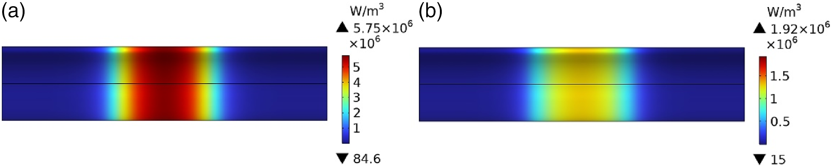
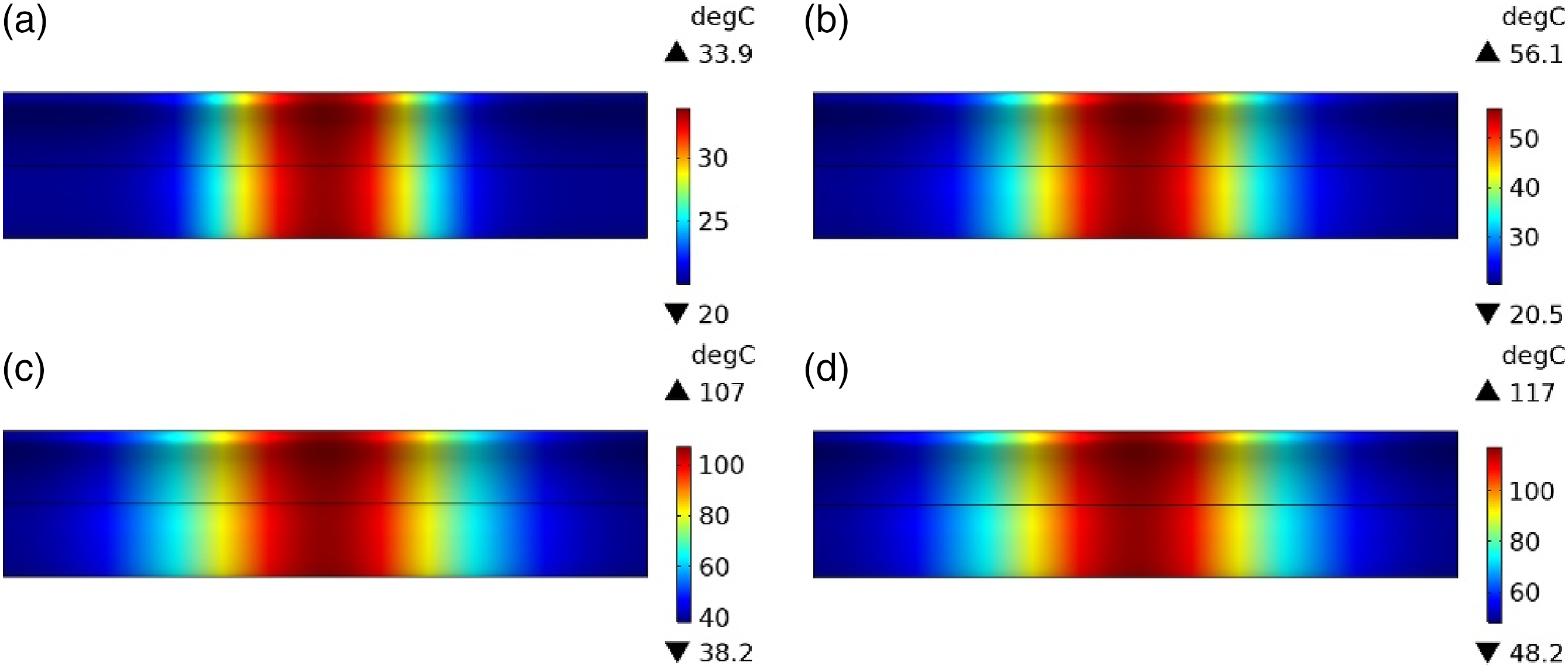
Figures 15 and 16 represent the cloud maps illustrating the temperature field variation in a CFRP wound circular tube heated by an external toroidal coil and an internal toroidal coil, respectively. In terms of temperature field distribution, both the external and internal toroidal coil heating methods exhibit a consistent rectangular pattern, and the temperature increase process is also similar. Initially, when the toroidal coil starts heating, a temperature rise is observed at the center position of the coil. As the heating time increases, the temperature field gradually spreads along the axis of the tube, and the temperature values continue to rise. After reaching 10 min, the temperature field appears rectangular, with the highest temperature values located at the center position of the coil. Comparing Figures 15 and 16, it can be observed that the maximum temperature value achieved when heating for 10 min is approximately 165°C higher in the case of the external toroidal coil heating compared to the internal toroidal coil heating. However, the difference in the area of the temperature field distribution at the center position of the coil is not significant between the two heating methods. This indicates that in practical heating processes, choosing the external toroidal coil heating method can achieve higher heating efficiency and faster temperature increase. Cloud map illustrating the variation of temperature field in a CFRP wound circular tube heated by an external toroidal coil. (a) Heating for 15 s (b) heating for 50 s (c) heating for 5 min (d) heating for 10 min. Cloud map illustrating the variation of temperature field in a CFRP wound circular tube heated by an internal toroidal coil. (a) Heating for 15 s (b) heating for 50 s (c) heating for 5 min (d) heating for 10 min.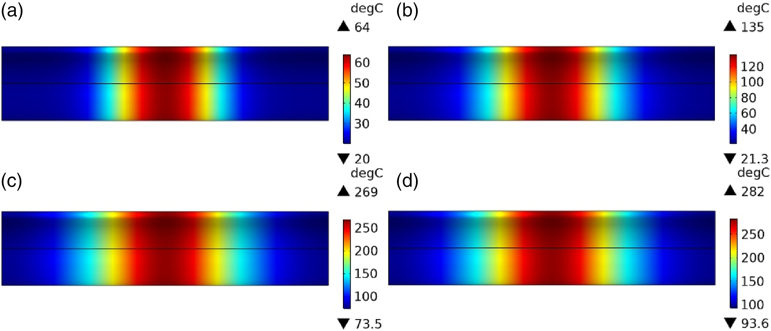
Experiment of heating CFRP wound round pipe by two heating methods
In order to verify the accuracy of the finite element model established herein, experiments on the temperature field distribution of CFRP wound circular tube heated by electromagnetic induction were conducted. Experiments were mostly consistent with the coil structure parameters set in the simulation. Figure 17 shows the schematic diagram of experimental platform for electromagnetic induction heating CFRP wound circular tube. Schematic diagram of electromagnetic induction heating CFRP winding round tube experimental platform.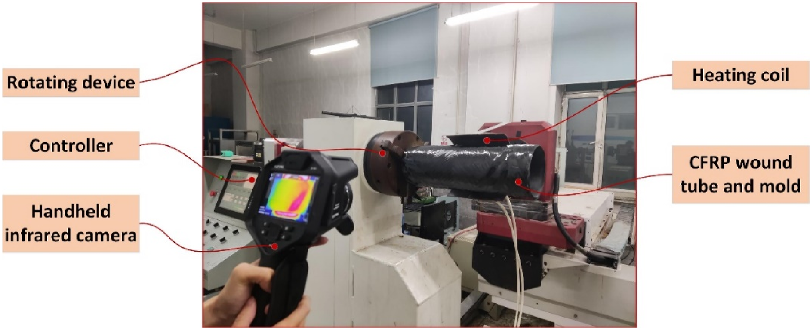
Since the external curved coil was placed on one side of the rotating circular tube, resulting in the temperature field variation pattern, which could not be observed clearly. Therefore, experimental plots were all images of the coil-free side. As shown in Figure 18, the temperature field distribution cloud of CFRP wound circular tube heated by external arc coil. The slight deviation in the temperature field distribution because of the irregular winding inside the CFRP wound circular tube, but from the figure we could find that the overall trend was basically the same as the simulation, inferring the reliability of this simulation. In the initial stage of heating, the temperature first increases in the region located directly facing the two vertical edges of the coil. As time progresses, the temperature field distribution expands gradually towards the surrounding areas. After heating for 10 min, the temperature field distribution becomes more uniform, and the temperature values closely match the simulation results. Cloud map of the temperature field distribution in a CFRP wound circular tube heated by an internally placed arc coil. (a) Heating for 15 s (b) heating for 50 s (c) heating for 5 min (d) heating for 10 min.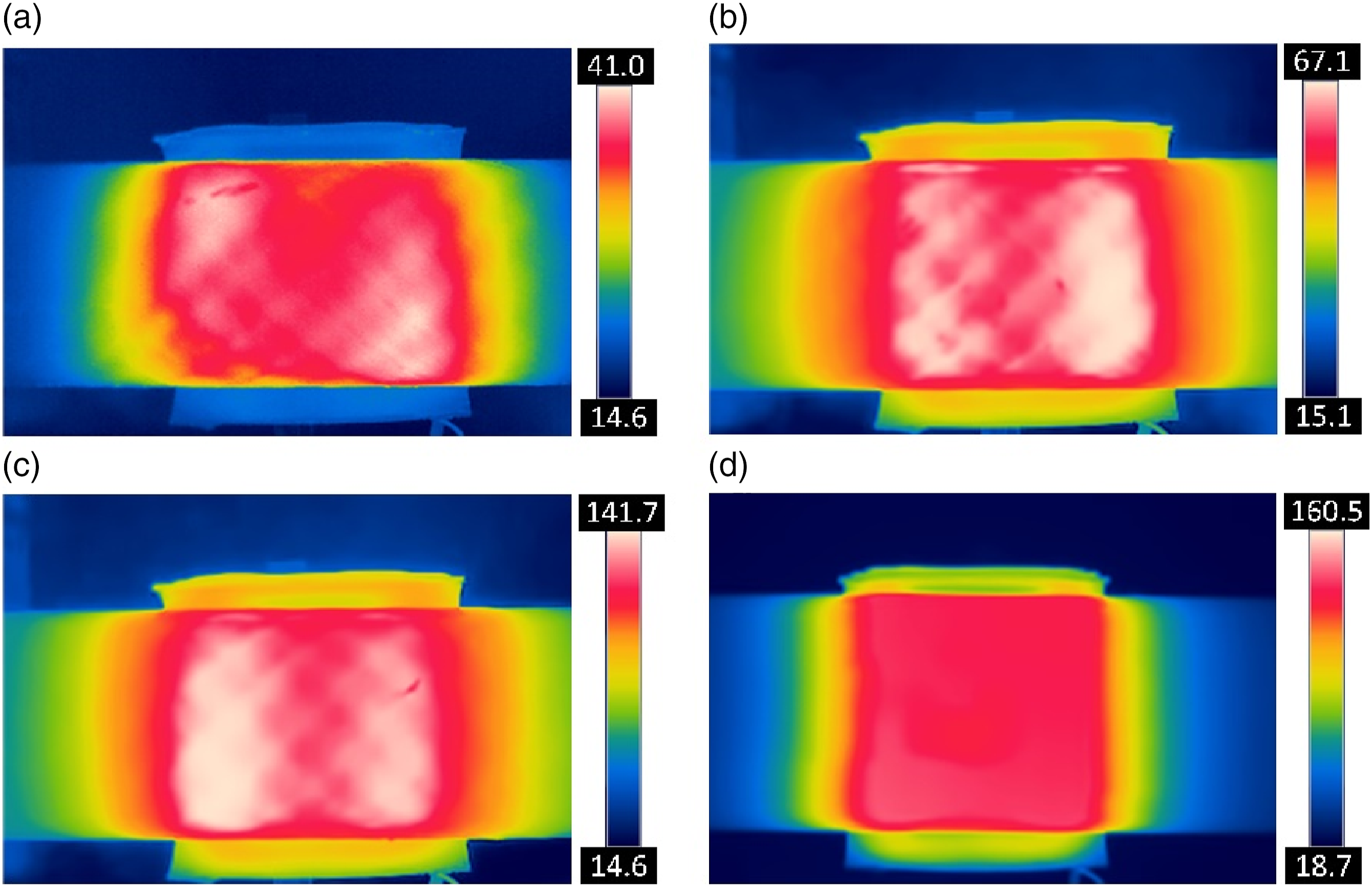
Due to the impedance of the coil in the external toroidal coil induction heating experiment, it was not possible to obtain the temperature field cloud map for external coil heating. Therefore, no experiments were conducted for external toroidal coil induction heating in this study. Figure 19 depicts the temperature field variation cloud map of a CFRP wound circular tube heated by an internally placed arc coil, from the beginning of heating to the steady-state temperature field. From the figure, it is evident that the temperature rises first at the center position of the coil, exhibiting a rectangular distribution. As time progresses, the temperature field gradually spreads along the axis of the tube, and when reaching a steady-state, the temperature field exhibits a rectangular distribution. Due to the irregular wrapping of the heated tube, the experimental results do not exactly match the simulation. However, it can be observed that the experimental temperature field distribution, heating trend, and temperature field variation pattern are consistent with Figure 16, demonstrating the reliability of the simulations conducted in this study. Cloud map illustrating the variation of temperature field in a CFRP wound circular tube heated by an internally placed toroidal coil. (a) Heating for 15 s (b) heating for 50 s (c) heating for 5 min (d) heating for 10 min.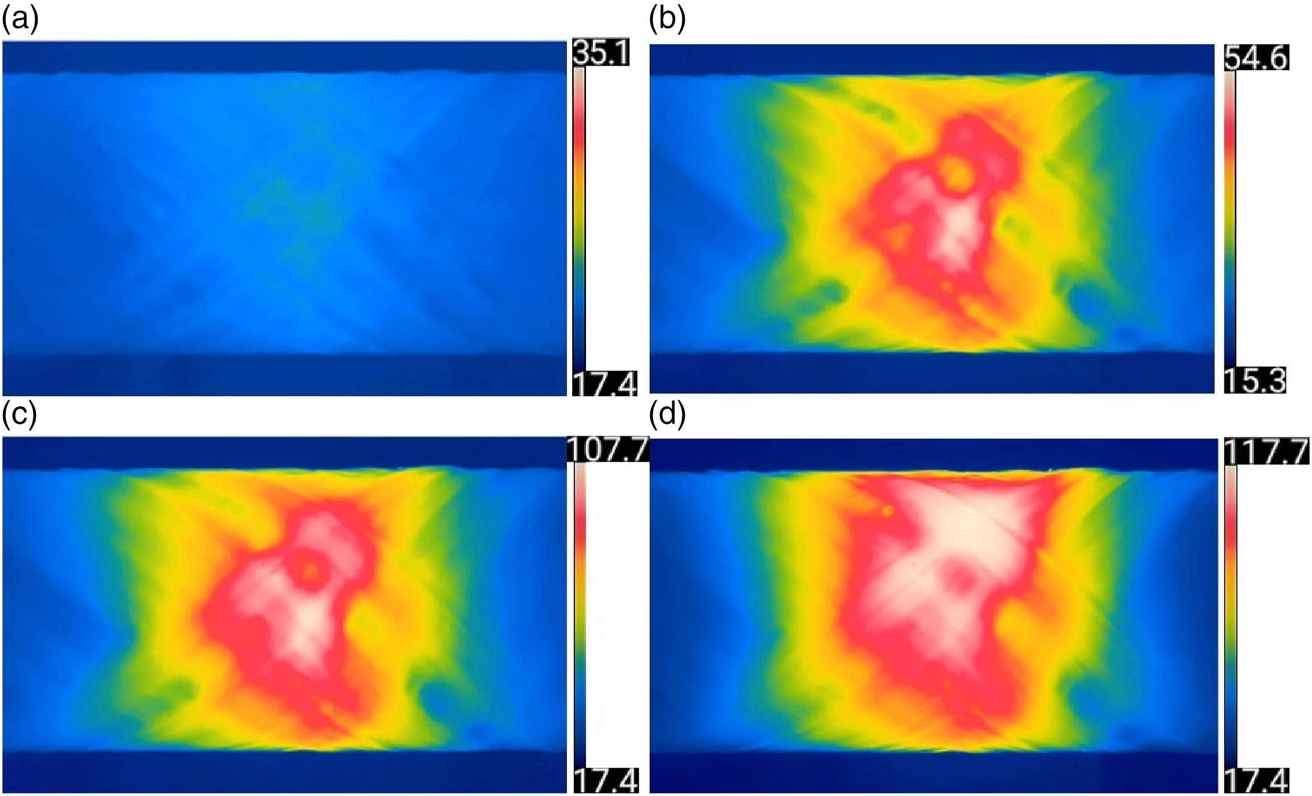
Conclusion
To achieve continuity of the magnetic field during the rotation process in the modeling of external arc coil induction heating, a grid movement method is employed in the geometric modeling. This involves performing set difference calculations and union operations on different domains to form consistent boundary pairs, enabling relative motion between the coil and the CFRP wound circular tube. The grid division is also an important factor influencing the continuity of the magnetic field. To ensure computational accuracy after the three-dimensional model is rotated, the density of the grids in adjacent regions of the consistent boundary pairs should match each other. Additionally, to represent the winding characteristics of the CFRP wound circular tube, anisotropic coefficients are set in a diagonal form, and the coordinate system is transformed from the spatial coordinate system to the cylindrical coordinate system. The simulation of external arc coil induction heating elucidates the heating mechanism of CFRP wound circular tubes. An alternating current generates an alternating magnetic flux, which, in turn, induces eddy currents within the closed-loop fibers. The combination of these eddy currents and the resistance of the material generates heat. Initially, the regions directly facing the two vertical edges of the coil experience heating, and then the heat gradually spreads to the surrounding areas until a state of rectangular distribution and uniform temperature is achieved. Due to the irregular winding of the heated tube, there may be slight discrepancies between the experimental and simulated results. However, the heating process and the temporal evolution of the temperature field distribution in the simulation are generally consistent, demonstrating the correctness of the simulation. The research focused on the induction heating processes of external toroidal coils and internal toroidal coils, providing magnetic flux density, eddy current distribution, heat generation, and temperature field distribution maps for the internal circular coil heating. It can be observed that, except for the inconsistent distribution of magnetic flux density, the distributions of other physical quantities are generally consistent, with differences only in numerical values. Regarding the temperature field values in the heating process, it can be noted that, for the same duration, the external toroidal coil achieves higher temperatures. This implies that choosing the external toroidal coil for practical heating processes can result in faster and higher temperature increases. In terms of temperature distribution, at the initial stage of heating, the temperature field first appears at the center position directly facing the coil, exhibiting a rectangular distribution. As heating time increases, the temperature field gradually expands along the axis of the circular tube, with the temperature values continuously rising. Once the set heating time is reached, the rectangular distribution no longer expands. This research aimed to provide alternative heating methods for CFRP wound circular tubes in different operating conditions during practical production, while also offering theoretical and data support. Simultaneously, the method employed in this paper to study the heating patterns of thermosetting composite materials is equally applicable to the investigation of the induction heating process for thermoplastic composite materials. The only difference lies in the magnitude of temperature values, providing a research framework for the induction heating of thermoplastic CFRP.
Footnotes
Declaration of conflicting interests
The author(s) declared no potential conflicts of interest with respect to the research, authorship, and/or publication of this article.
Funding
The author(s) disclosed receipt of the following financial support for the research, authorship, and/or publication of this article: The authors would like to thank Shandong Provincial Natural Science Foundation, China (ZR2023ME064) for funding this work.
Data availability statement
Data sharing not applicable to this article as no datasets were generated or analysed during the current study.