
Abstract
This article investigates the eccentric ballistic impact response of square aluminum and fiber-metal laminated plates with the ANSYS AUTODYN hydrocode. The plates are impacted by a cylindrical projectile with normal high velocity. The validation of the numerical procedure is mainly carried out through comparisons with published experimental data. The modeling procedure and the verification of numerical results are described in detail so as to provide a useful reference. The effect of impact point eccentricity and different boundary conditions on the ballistic resistance of the targets is evaluated. It is found that the ballistic limits of the considered targets can be substantially affected by the boundary conditions and the eccentricity of impact. The targets are sorted in a descending order of ballistic resistance which is found invariant to the impact position.
Keywords
Introduction
Fiber Metal Laminates (FMLs) are hybrid composite materials built up from thin metal alloy sheets into one laminate with intermediate fiber/polymer layers. The purpose of FMLs is to take advantage of metal and fiber-reinforced composites in order to provide superior mechanical properties to these material systems. 1 FMLs have critical benefits such as low density, high fatigue resistance, excellent corrosion and fire resistance, which make them ideal for aerospace, automotive and other structural applications. 2 GLARE (GLAss REinforced) consists of aluminum alloy and glass-fiber reinforced epoxy layers and it is the most successful FML up to now considering the variety and range of its applications. GLARE has been applied in the production of large parts of the Airbus A380 upper fuselage and the Boeing 777 impact resistant bulk cargo floor, while new manufacturing technologies are attracting increasing interest for further future utilization.2,3
Impact performance is another significant advantage of FMLs, especially when compared with fiber-reinforced composite materials. For example, the impact resistance of aluminum based FMLs is comparable to conventional monolithic aluminum whereas their constituent composite material has substantially lower impact resistance. 2 Aerospace structures are often subjected to unwanted, though unavoidable impact incidents which cover a wide range of velocities and geometries of the colliding bodies. For example, the maintenance damage from dropped tools is a low velocity impact, while the bird strike or hail occur at higher impact velocities. Considering space applications, hypervelocity impact is likely to occur with micrometeroids and orbital debris and poses a long-term threat to spacecraft and spacesuits. 4 Hence, the evaluation of the impact resistance of such structures is very important and its study concerning metals, composites and FMLs is an intensive field of scientific research.4–12 The prediction of the ballistic impact response of structures impacted by free-flying projectiles with high initial velocity 5 is the goal of intensive research as well and some representative studies are referenced in the next two paragraphs.
Hoo Fatt et al. 13 developed an analytical model to predict the ballistic limit and energy absorption of GLARE panels subjected to ballistic impact by a blunt cylinder. Their analytical ballistic limits are in good agreement with their experimental values concerning GLARE 5 plates. They also compared the experimental ballistic impact performance of GLARE with monolithic 2024-T3 aluminum plates. Yaghoubi et al.14,15 studied numerically and experimentally the ballistic impact response of GLARE 5 beams. In references16,17 the same authors investigated the ballistic impact behavior of GLARE 5 plates. The ballistic analysis of FMLs impacted by flat and conical impactors has been conducted by Zarei et al. 18 numerically and experimentally. Bikakis et al. 19 studied the ballistic impact response of FMLs and monolithic metal plates consisting of different aluminum alloys. They found that the ballistic limit of the panels can be substantially affected by the constituent aluminum alloy. Chen et al. 20 carried out an experimental investigation on normal and oblique ballistic impact behavior of FMLs when subjected to impact by a flat-faced cylindrical projectile. In the study of Bandaru et al., 21 the ballistic impact response of Kevlar-reinforced thermoplastic composite armors is investigated experimentally. They also carried out hydrocode simulations using ANSYS AUTODYN to estimate the ballistic limit and simulate the failure modes of the armors.
The effect of projectile eccentricity and obliquity on the ballistic impact performance of aluminum hemispherical shells is investigated by Khaire et al. 22 numerically. Their results showed that the ballistic performance of the target was influenced by both the eccentricity and obliquity of the projectile. Tiwari and Khaire 23 investigated the ballistic impact behavior and energy dissipation characteristics of cylindrical honeycomb sandwich shells carrying out experimental and numerical simulations. In reference 24 the ballistic impact performance of steel-based FML targets was studied. A specific sample of this study consisted of stainless steel, aramide fabric and an intermediate layer of a bag filled with a liquid mixture. A combined finite element method and smooth particle hydrodynamics modeling procedure was implemented in order to simulate the impact event for this specific target.
Based on the above, it is worth noting that although a lot of research has been already published concerning the ballistic impact response of metal or composite targets impacted centrally by projectiles, very few studies investigate the effect of impact point eccentricity. However, in real-life hazards such as bird-strike, runway debris and hail strikes on the outer surface of aerospace structures, the possibility of the impact point to be located at a position other than the center of the panel (e.g., near the supporting stiffeners at the boundaries of the panel) is rather significant. Therefore, evaluating the effect of impact point eccentricity on the ballistic resistance of targets consisting of metals, composites or FMLs, has important practical implications.
The present article deals with the ballistic impact performance of aluminum, which is still a basic aerospace material, and FML panels. More specifically, an extensive numerical study has been carried out to investigate the effect of impact point eccentricity and different boundary conditions (bc) on the ballistic resistance of square monolithic 2024-T3 aluminum and GLARE plates impacted by a cylindrical projectile. The ANSYS AUTODYN hydrocode 25 is used for this purpose. The numerical models of this study have been validated using corresponding numerical and experimental results obtained from published articles concerning normal central impact of aluminum and GLARE panels. To date, there is not any published study considering the eccentricity of the ballistic impact load on unidirectional (UD) glass fiber-reinforced FML plates, according to the authors’ knowledge. Furthermore, the results of the present investigation elucidate the behavior of aluminum and GLARE plates subjected to eccentric ballistic impact and will help engineers and researchers to understand how different boundary conditions can affect the response of these targets.
Problem definition
In this article, the investigation of the ballistic resistance of targets impacted by a cylindrical projectile is carried out considering the structural arrangement of the impact experiments of reference.
13
Specifically, square aluminum or GLARE plates are considered with in-plane dimensions equal to 15.24 cm × 15.24 cm. The projectile is flat-faced cylinder, 2.54 cm long with 1.27 cm diameter, and its initial velocity vector is normal to the panel. The mass of the projectile is equal to 14.125 g and its impacting face has a small radius of 0.08 cm. Apart from the central impact, four additional positions are considered on the target surface in order to study the effect of impact point eccentricity as shown and numbered in Figure 1. The origin of the coordinate system depicted in Figure 1 is at the center of the panel. Plan (top view) of the five positions of the projectile impact on the plate (all dimensions in cm).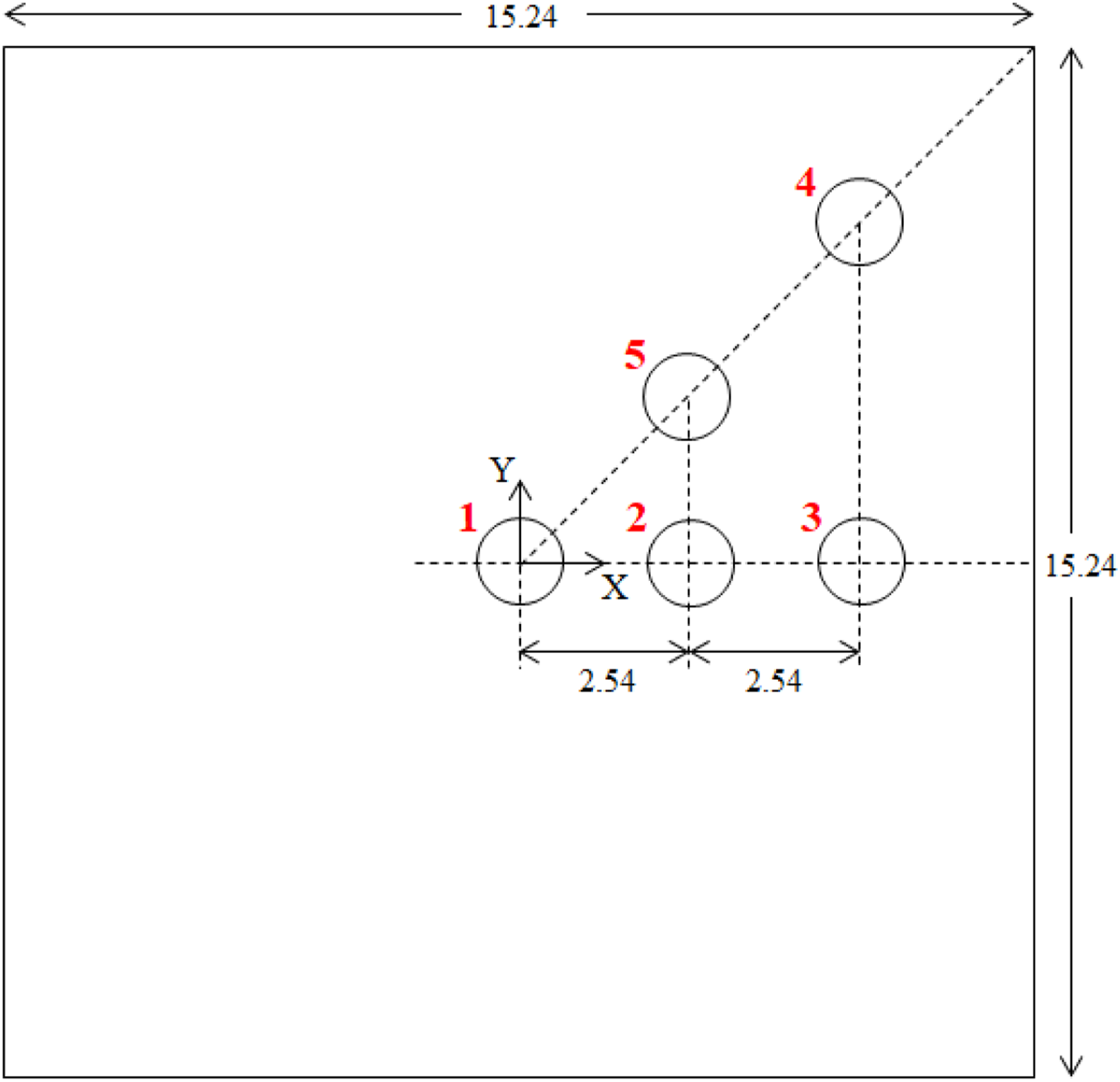
Two different types of bc are considered for the panels. The first type is clamped (C) bc along the four edges of the panel. The second type is mixed (M) bc: the two opposite edges (Y = 7.62 cm and Y = −7.62 cm in Figure 1) are clamped and the other two edges (X = 7.62 cm and X = −7.62 cm in Figure 1) are simply supported. The application of both support types is described in the next section. The evaluation of the effect of the considered bc on the ballistic impact resistance of aluminum and FML panels is critical since both types of bc are used for the analysis of real aerospace structures. Aircraft skin consists of thin panels supported on structural members such as stringers, frames, bulkheads, etc. For the purpose of impact analysis, the panels among supporting members could be analyzed approximately as isolated rectangular plates with suitable bc. Clamped and simply supported bc are classical idealizations of the supporting structure. For example, a fuselage panel supported transversely between bulkheads and longitudinally between stringers can be considered to be clamped in way of the bulkheads and simply supported in way of the stringers i.e., it has mixed bc.
The ballistic limit is the threshold projectile velocity above which the panel fails by perforation 50% of the time. The corresponding initial kinetic energy of the projectile is absorbed during the panel perforation. The basic energy absorption mechanisms in FMLs are: 13 global panel deformation, delamination among glass-epoxy layers, petaling of aluminum layers, tensile fracture of glass-epoxy layers. The global panel deformation includes bending and stretching of the aluminum and prepreg layers of the FML. The ballistic impact of the projectile on the target is a transient nonlinear phenomenon involving contact interaction, large strains and deflections, plasticity and fracture. The ballistic limits of the considered panels are calculated numerically with ANSYS AUTODYN hydrocode and are studied in order to assess the effect of impact point eccentricity and different bc on their ballistic resistance.
It is noted that the geometry, the structure and the bc of the considered targets are symmetric about the X-axis and about the Y-axis. Consequently, impact positions 2 and 3 also represent the two symmetric impact positions located along the negative direction of X-axis. Impact positions 4 and 5 also represent the four symmetric impact positions located along the diagonals of the second and fourth quadrant of the X-Y coordinate system. Then, the diagonal impact positions of the second quadrant also represent the two symmetric impact positions located along the diagonal of the third quadrant. As a result, the impact positions of Figure 1 represent eight additional impact positions at the aforementioned locations which practically cover the whole plate area, apart from the area close to Y-axis. In the special case of aluminum target with clamped bc the geometry, the structure and the bc of the target are also symmetric about the diagonals of the plate. The impact positions of Figure 1 now represent twelve additional impact positions including the four symmetric locations along the Y-axis.
Numerical modeling procedure
A three-dimensional modeling procedure based on the finite difference method and Lagrangian grid is carried out using the ANSYS AUTODYN hydrocode, 25 in order to predict the ballistic limit of square panels impacted centrally and eccentrically by a cylindrical projectile flying normal to the target. The panels consist of FML or monolithic aluminum. The projectile is modeled as a rigid body since its material has adequate strength and hardness. 13 This modeling choice is justified and lowers the computational cost of the problem and is also used in the ballistic impact studies of references.13,18,19,20,22,23,26
The aluminum or FML plate and the projectile are discretized with Lagrangian grids consisting of hexahedral eight-noded volume elements (cells). The grid of the projectile is the same for all models. A very dense grid is used for the discretization of the impactor for two reasons: the first reason is to represent accurately its geometry, including the 0.08 cm radius of its impacting face. The second reason is to achieve and incorporate into the numerical analysis correct values concerning the mass, the inertia tensor and the mass center position of the projectile. Correct values of these quantities are necessary since the trajectory of the projectile during eccentric impact can change through its rotational motion, as it is demonstrated in section Results and discussion.
In Figure 2, the cross-section of a GLARE 5-2/1-0.5 plate and the Lagrangian grid corresponding to the central ballistic impact of the same plate (89,888 cells) along with the projectile (29,044 cells) are illustrated. The definition of the thickness and the density of each layer are depicted in Figure 2(a). It is noted that the average areal weight density of the GLARE 5 plate equals to 37.46 N/m2 (calculated using the theoretical values of density and dimensions), while the areal weight density of the aluminum plates with thickness 0.16 cm and 0.32 cm equals to 43.46 N/m2 and 86.93 N/m2, respectively. As shown in Figure 2(c), the number of hexahedral cells along the thickness of each aluminum (blue color) and glass-epoxy (green color) layer, is two and one, respectively. Thus, GLARE 5-2/1-0.5 is always simulated with a total of eight cells in the thickness direction. It is noted that eight hexahedral finite elements are used by Yaghoubi et al.14,15,17 and Bikakis et al.
19
in order to mesh GLARE 5 panels in the thickness direction. The aspect ratio of the cells is constant throughout the area of the plate. The aspect ratio of the cells is 5.66 and 11.32 in aluminum and prepreg layers, respectively. It has been verified in the present study that satisfactory convergence of the predicted ballistic limits has been achieved for each examined impact case between the predictions of a coarse and a fine model consisting of uniform target grids but with increased in-plane grid density. The GLARE 5 plate in the coarse model consists of 45,000 cells. Cross-section and fine Lagrangian grid of a GLARE 5-2/1-0.5 plate along with the rigid projectile: (a) cross-section, (b) isometric and (c) side view.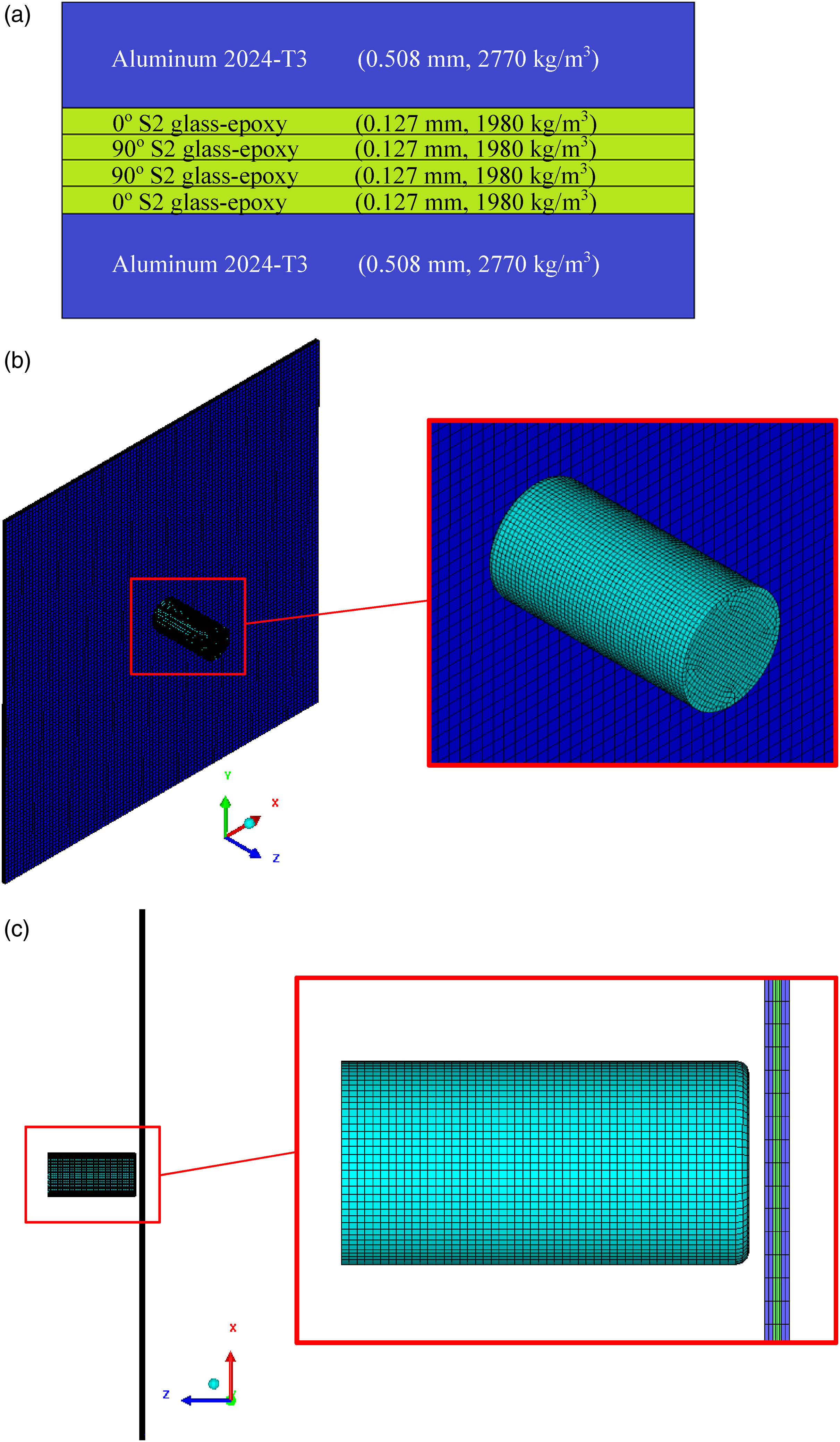
As described in the previous section, two types of bc are considered. The clamped bc are applied by setting all translational and angular velocity components of the grid points located at the clamped faces of the target equal to zero. The simply supported bc are applied by setting equal to zero the normal to the plate translational velocity component of the grid points located at the supported edges of the non-impacted surface of the target.
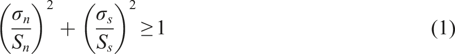
The contact between adjacent layers of the FML plates is modeled with breakable bonded face connections. More specifically, the bonded connection fails and the bond of adjacent layers breaks when a user-defined stress failure criterion predicts, in order to model delamination between composite layers or debonding between aluminum and composite layers. In this study, the stress failure criterion proposed by Chang and Springer is employed:
27
The contact between the projectile and each layer of the target is simulated with Lagrange/Lagrange frictionless body interactions in combination with the penalty method.25,28 The same procedure is implemented for the interactions among the layers.
The simulation of the penetration of the panels by the projectile is accomplished through the numerical mechanism of erosion. Cells are automatically deleted during the solution when the failure criteria described in the following paragraphs for aluminum and glass-epoxy are satisfied.
It is noted that contact (sliding) energy is present during the impact simulation because of the defined contacts. However, it is always verified that the contact energy is very low in comparison with the peak internal energy of the striker-target system, as it should be, since friction is not included in the contact definition. Frictionless simulations of ballistic impacts are also implemented in references.13,14,15,17,19
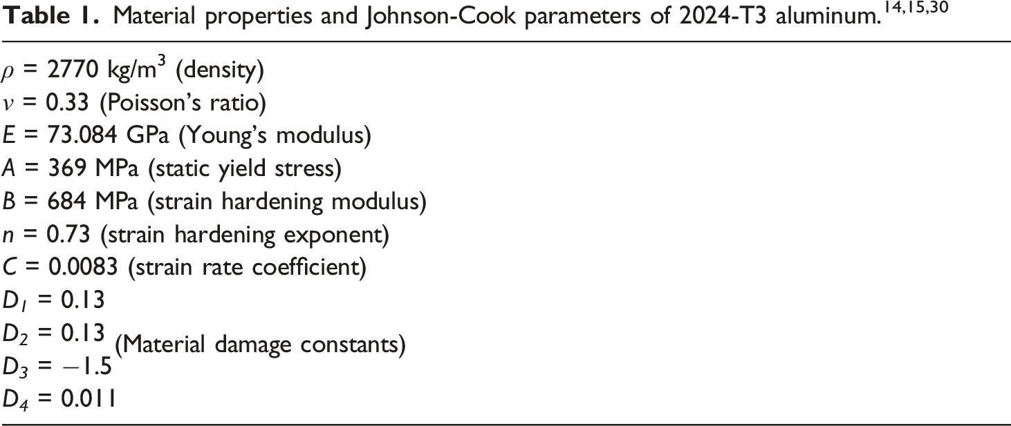
The aluminum alloy of the isotropic and FML plates is modeled as an elasto-plastic material with rate-dependent behavior using the simplified Johnson-Cook plasticity material model:25,29

The damage of aluminum is also considered with the Johnson-Cook failure model expressed by the following cumulative damage law:25,29
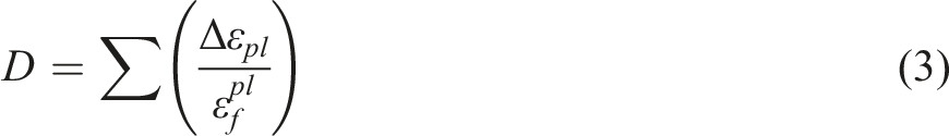

Δε
pl
is the increment of the equivalent plastic strain during an increment in loading,
It is considered that the impact cases of this study occur at room temperature. Therefore, the temperature effect of the Johnson-Cook plasticity material and failure models 29 is not considered, as in references.14,15,17,19,30
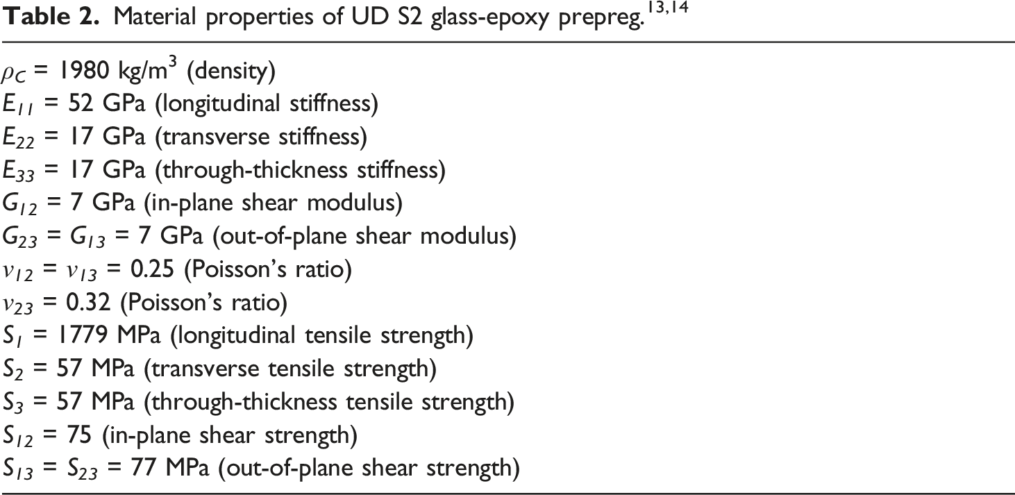
The material behavior of the composite layers in the FMLs consisting of UD S2 glass-epoxy prepreg is idealized with the orthotropic elastic model. Inherent in this model, is the assumption of a linear volumetric elastic response of the material.
25
The failure of the UD glass-epoxy layers is predicted with the maximum stress failure criterion of AUTODYN which is suitable for modeling impact events on UD glass-epoxy composites25,28 and allows different tensile and shear strengths corresponding to the principal material directions. Namely, failure occurs when any one of the following six inequalities is satisfied:

Apart from modeling the projectile as a rigid body the volume cells are used with single point integration in order to further reduce the computational cost. However, the combination of hexahedral volume cells with single point integration can lead to “hourglass” modes of deformation and these hourglassing effects may cause degradation of the numerical results. For this reason, it is verified for all impact cases analyzed in this study, that the hourglass energy is low relative to the internal energy of the system. It is also verified as described in the Results and discussion section that the numerical results satisfy the momentum and energy conservation laws.
It is noted that the described numerical modeling procedure can be applied to other fiber-metal laminated material systems consisting of metal layers and thermoplastic fiber-reinforced composite layers, such as glass fiber-reinforced poly-ether-imide (PEI) composites and carbon fiber-reinforced poly-ether-ether-ketone (PEEK) composites. The material properties of the numerical models must be updated accordingly.
Concisely, ANSYS AUTODYN explicit dynamics software is used to model ballistic impacts. The impactor has a predetermined initial velocity and strikes on the target causing its complete penetration, as long as this initial velocity is greater than or equal to the ballistic limit. The prediction of the unknown ballistic limit of the panel is accomplished through the execution of several trials with different initial projectile velocity. For the first trial, an estimated initial projectile velocity is determined. The projectile will be stopped or it will perforate the target. If the projectile is stopped, the trial velocity is increased whereas if the projectile perforates the target the trial velocity is reduced in order to define an impact velocity range between incomplete penetration and perforation of the target. This velocity range is bisected to determine the subsequent trial projectile velocity and narrow the impact velocity range. The bisection is repeated until the impact velocity range becomes 1 m/s. For example, when a ballistic limit equal to 128 m/s is predicted, the projectile is stopped for an impact velocity of 127 m/s (incomplete penetration) whereas the projectile perforates the target for an impact velocity of 128 m/s. The termination time of each impact analysis is predetermined and allows for the complete penetration of the panel.
Validation of numerical models
Each aluminum and prepreg layer in the GLARE plate has a thickness of 0.508 mm and 0.127 mm, respectively. GLARE 5-2/1-0.5 FML consists of the following stacking sequence:
The density of the rigid projectile’s material is defined so that the projectile mass calculated using its exact volume is equal to 14.125 g. It is verified that the geometry of the projectile is represented accurately with the very dense grid since the projectile mass calculated from the volumes of its cells and the defined density during the numerical solution is equal to 14.08 g (0.32% deviation from the exact mass and within the range given in). 13
Comparison between numerical (ANSYS AUTODYN) and experimental 13 ballistic limits.
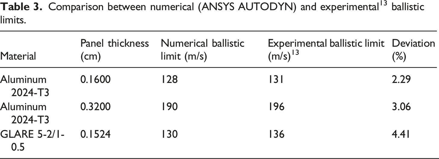
In order to further validate the numerical procedure, the striker kinetic energy time history curve of a GLARE 5-2/1-0.5 FML impacted centrally by the rigid projectile is compared with the respective curve derived using the finite element models and the modeling procedures of reference
19
with ANSYS LS-DYNA. A very good agreement between the two curves is observed in Figure 3. The ballistic limits of Table 3 have also been predicted in reference
19
and the predictions of the two different numerical modeling procedures are in close agreement. This fact enhances further the validity of the numerical modeling procedure described in the previous section.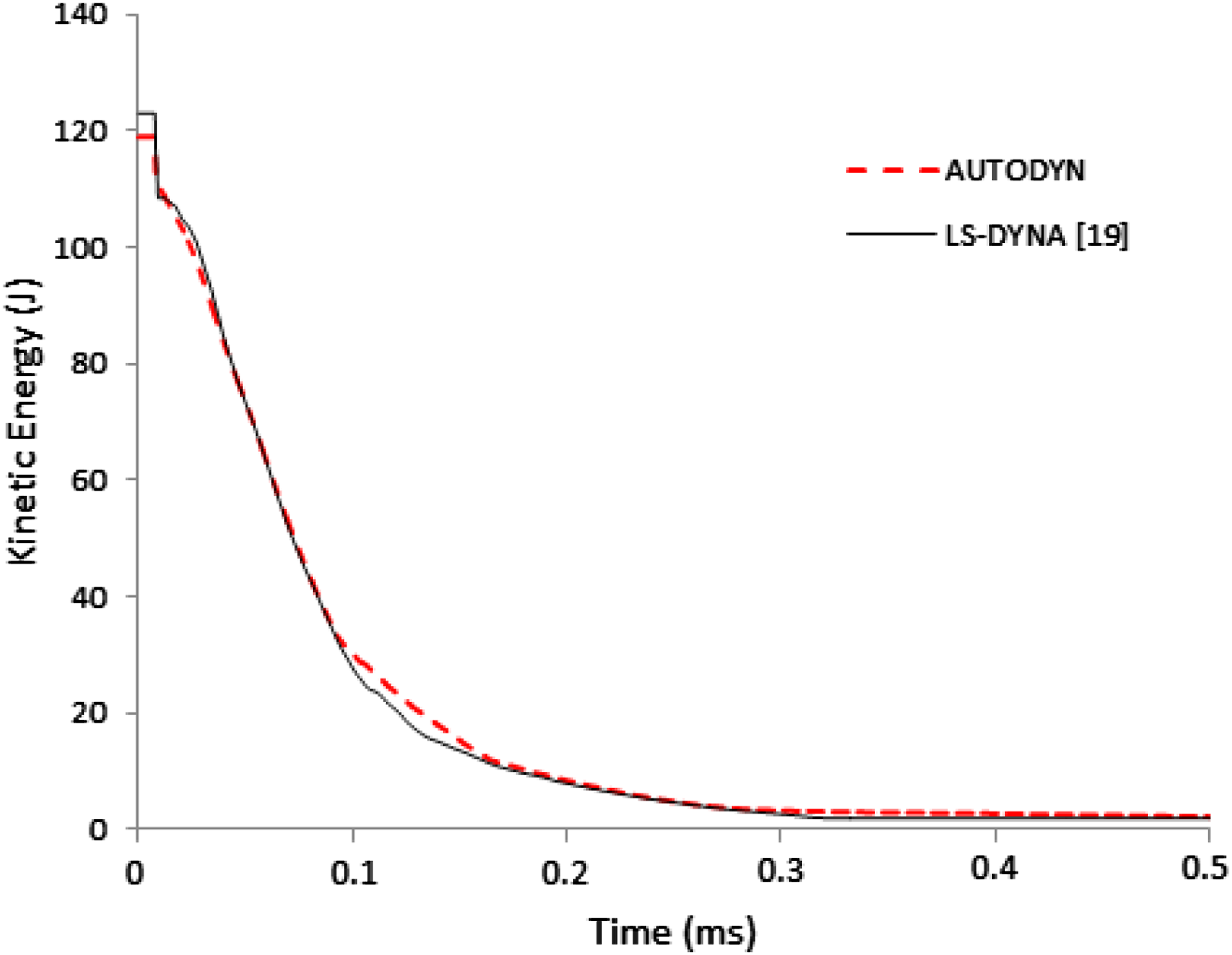
Since according to the authors’ knowledge there are not any published experimental or theoretical results concerning the eccentric ballistic impact of FML plates, the numerical procedure presented in this article is validated with central normal ballistic impact data and is then adjusted to investigate the effect of impact point eccentricity. The same reasoning of validation has been used by other researchers, for example in the numerical studies of references.22,31 Specifically, the eccentric ballistic impact 22 and blast loading 31 is investigated on hemispherical shells and armored plates, respectively. However, the validation of their numerical procedure considers comparisons with experimental results without eccentricity concerning the ballistic impact and blast response of the examined targets.
Results and discussion
Conservation of momentum and energy
The aforementioned validated numerical models of 2024-T3 aluminum (0.16 cm thickness) and GLARE 5-2/1-0.5 plates with fine grid are used in order to study the effect of the impact point eccentricity and different bc on the ballistic impact performance of these materials. The convergence of the calculated ballistic limits and the low levels of hourglass and contact energy were verified for all of the 20 analyzed ballistic impact cases.
In order to verify that the ballistic limits calculated with the fine grid models do not change by further increasing the in-plane grid density of the target, two very fine grid models were built. More specifically, for the central impact of aluminum and the eccentric impact case 4 (as depicted in Figure 1) of GLARE 5, both with clamped bc, very fine models consisting of a large number of hexahedral elements were built. It was found that the ballistic limits calculated with the very fine models and the ballistic limits of the corresponding fine models were practically the same.
The large number of elements of the very fine models increases significantly the solution time using the available computational power and renders the aforementioned bisection procedure concerning the prediction of the unknown ballistic limits unmanageable. For this reason, taking into account the verified independence of the calculated ballistic limits from the change of grid density for the two impact cases of the previous paragraph, the fine grid models described in section Numerical modeling procedure are used in this study for the numerical modeling of the 20 ballistic impacts of GLARE 5 and aluminum plates. A similar approach due to limitations of the computational power is described in references.14,15
In Figure 4 the internal energy time history curves corresponding to increasing grid density of the clamped aluminum plate impacted centrally by the rigid projectile with the ballistic limit velocity calculated for each grid are depicted. The curves of the coarse, fine and very fine models of Figure 4 correspond to 36,450 (135 × 135 × 2), 72,962 (191 × 191 × 2) and 145,924 (191 × 191 × 4) cells of the target, respectively. It is shown from Figure 4 that the internal energy time histories converge as the grid density increases. The time histories of the fine and very fine models practically coincide. The internal energy of the striker-target system includes elastic strain energy and work done in permanent deformations. Since the projectile is rigid and has zero internal energy, it is concluded from Figure 4 that the strain energy time histories of the plate converge as well. It is noted that the strain energy time history of the aluminum plate is associated with the evolution of its deformed shape during the impact. Consequently, the convergence of the plate’s strain energy time histories implies the convergence of the deformed shapes presented in the next subsection as well. Internal energy time histories corresponding to increasing target’s grid density for the central ballistic limit velocity impacts (case 1) of the 0.16 cm thick aluminum plate with clamped bc.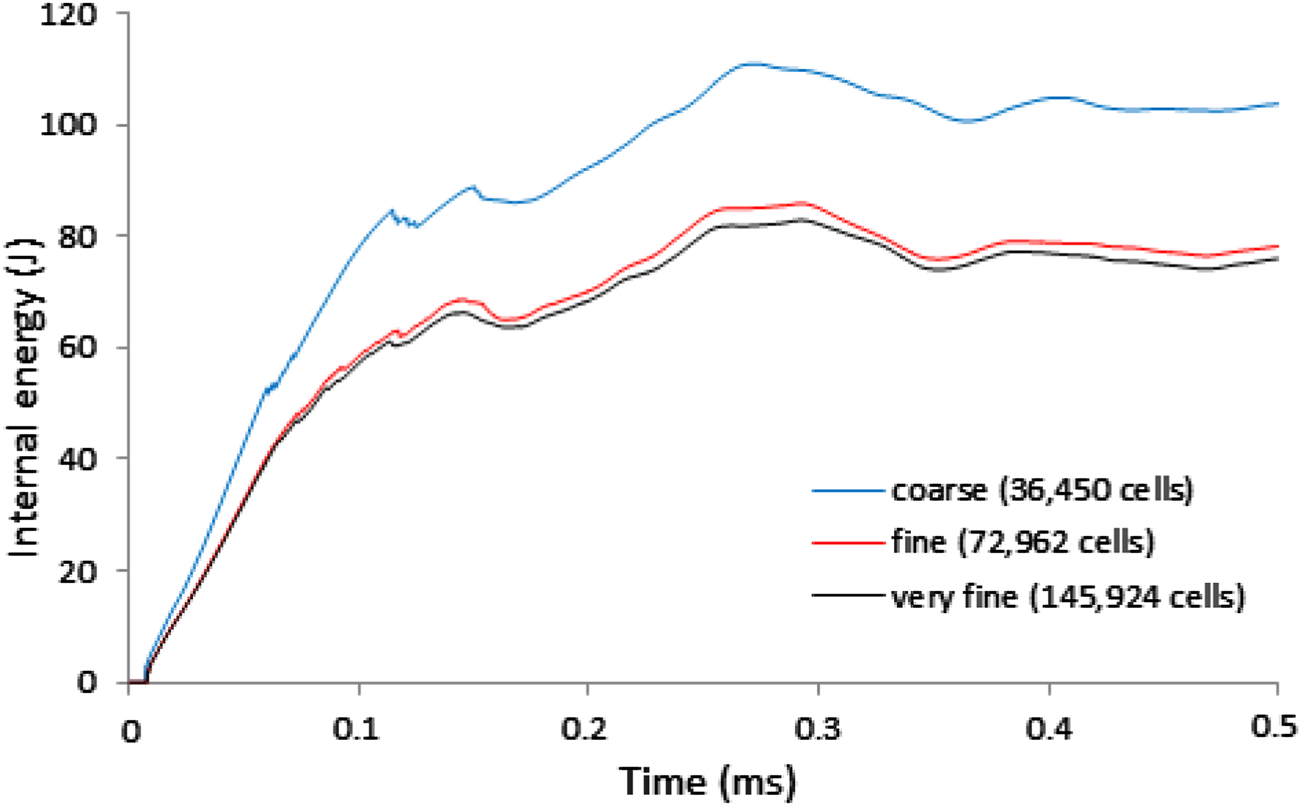
The partial differential equations that need to be solved during the explicit dynamic analysis with ANSYS AUTODYN express the conservation of mass, momentum and energy in Lagrangian coordinates. 25 Therefore, momentum and energy conservation indicate the quality of the solution, since in a well-posed simulation, mass, momentum and energy should be conserved.
According to the linear impulse-momentum theorem:
28

Equation (6) is equivalent to:
Equation (7) leads to three algebraic equations, namely:
Theoretically, if the momentum of the striker-target system is conserved, any momentum variation is caused by the impulse and equation (8) yields that J
i
− Δp
i
= 0. The quantity J
i
− Δp
i
is defined as the momentum balance error in AUTODYN. In Figure 5 the Momentum, impulse and error time histories in the Z-direction of the impact case 4 of a GLARE 5 panel with clamped bc.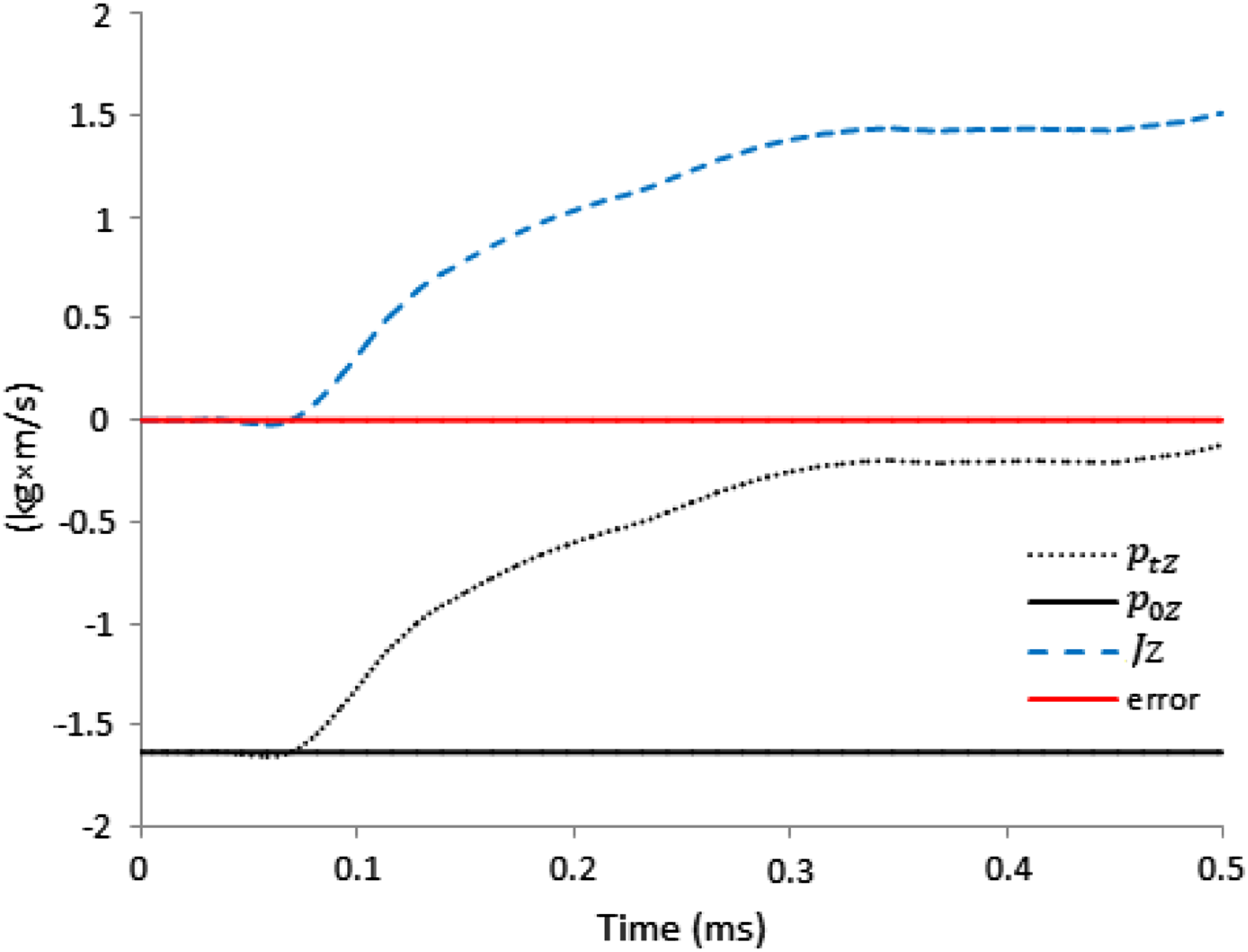
In order to verify that the energy of the striker-target system is conserved, the work done is first calculated as follows:
25

W ext is the external work and
E c is the contact energy
According to the energy conservation law:
28

E
t
is the current energy of the system, which is given by:
E k is the current kinetic energy of the system
Taking into account equations (10) and (11) the following equation is obtained:
Theoretically, if the energy of the striker-target system is conserved, the energy error W2 – W1 defined in AUTODYN should be equal to zero. In Figure 6 the E
t
, E
o
, W1 and energy error time histories of the system are depicted for the 4th impact case of a clamped GLARE 5 panel impacted by the projectile with the ballistic limit velocity. It is observed from Figure 6 that the initial energy of the system is equal to the projectile’s initial kinetic energy and the initial work done is as expected equal to zero. The current energy gradually decreases as the absolute value of the work done during the collision is increased. The E
t
and W1 time histories follow the same trend in accordance with equation (10). It is also observed from Figure 6 that energy error is very small, a fact that demonstrates the validity of the energy conservation law for the specific numerical model. It has been verified that the energy error is very small for the 20 impact cases analyzed in this study. Energy, work done and error time histories of the impact case 4 of a GLARE 5 panel with clamped bc.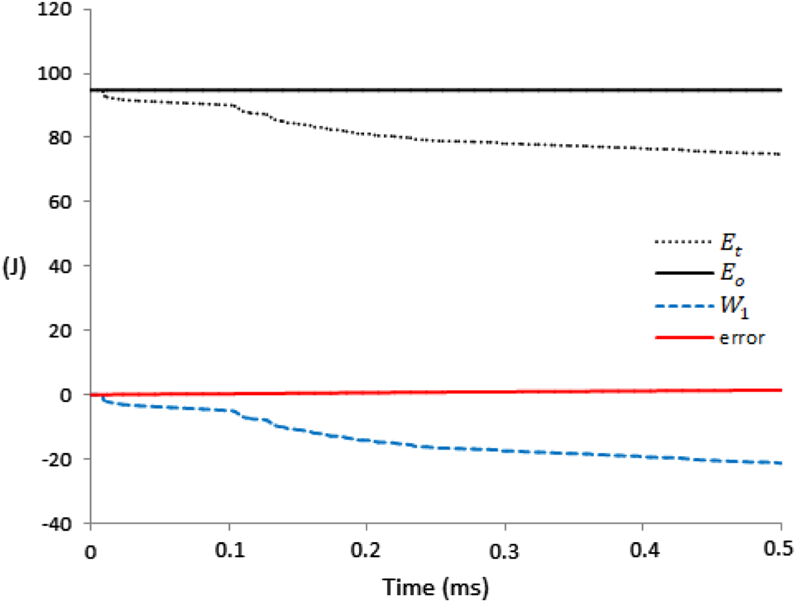
Eccentric and central perforation
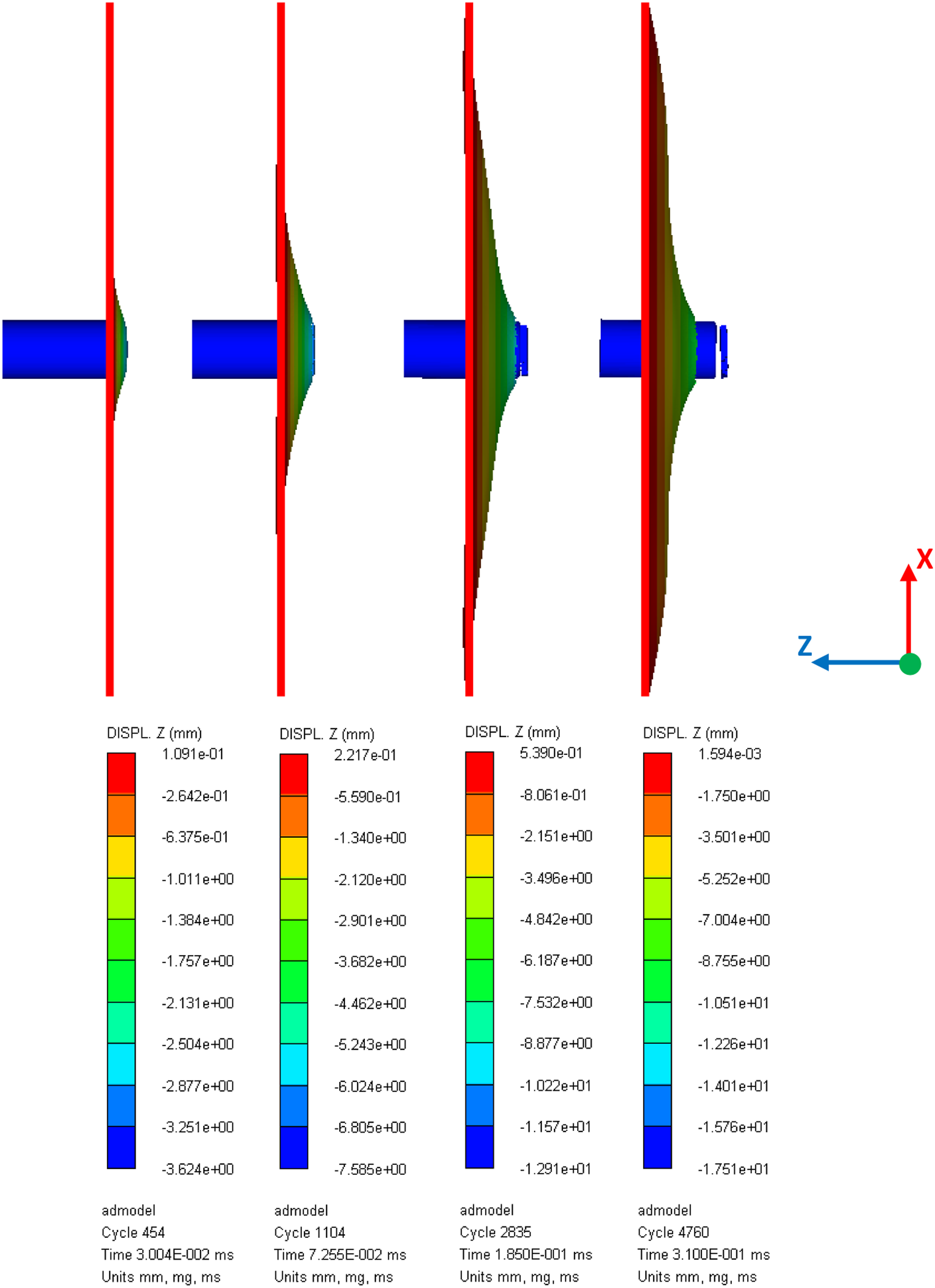
In Figures 7–9 representative displacement contours and the deformed shape of the target-striker system are shown at characteristics stages of the examined ballistic impact phenomenon. In these figures the side view of the Z-displacement contours is depicted in mm for clamped aluminum panels. It is noted that the Z-component of displacement is normal to the panel and parallel to the initial projectile’s velocity. The impacting face of the striker is initially located at a distance of 1 mm from the target. Side view of Z-displacement contours of an aluminum panel with clamped bc impacted eccentrically (case 3) by a rigid projectile at characteristic stages during the impact phenomenon. Side view of Z-displacement contours of an aluminum panel with clamped bc impacted eccentrically (case 2) by a rigid projectile at characteristic stages during the impact phenomenon. Side view of Z-displacement contours of an aluminum panel with clamped bc impacted centrally (case 1) by a rigid projectile at characteristic stages during the impact phenomenon.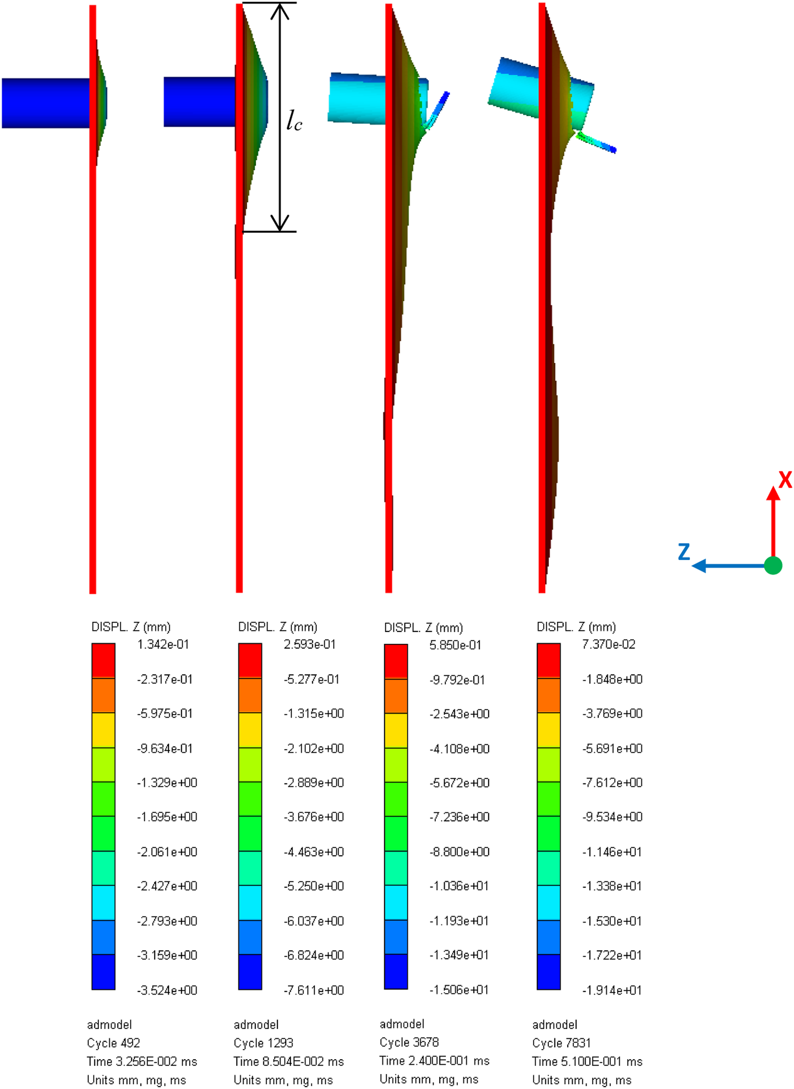
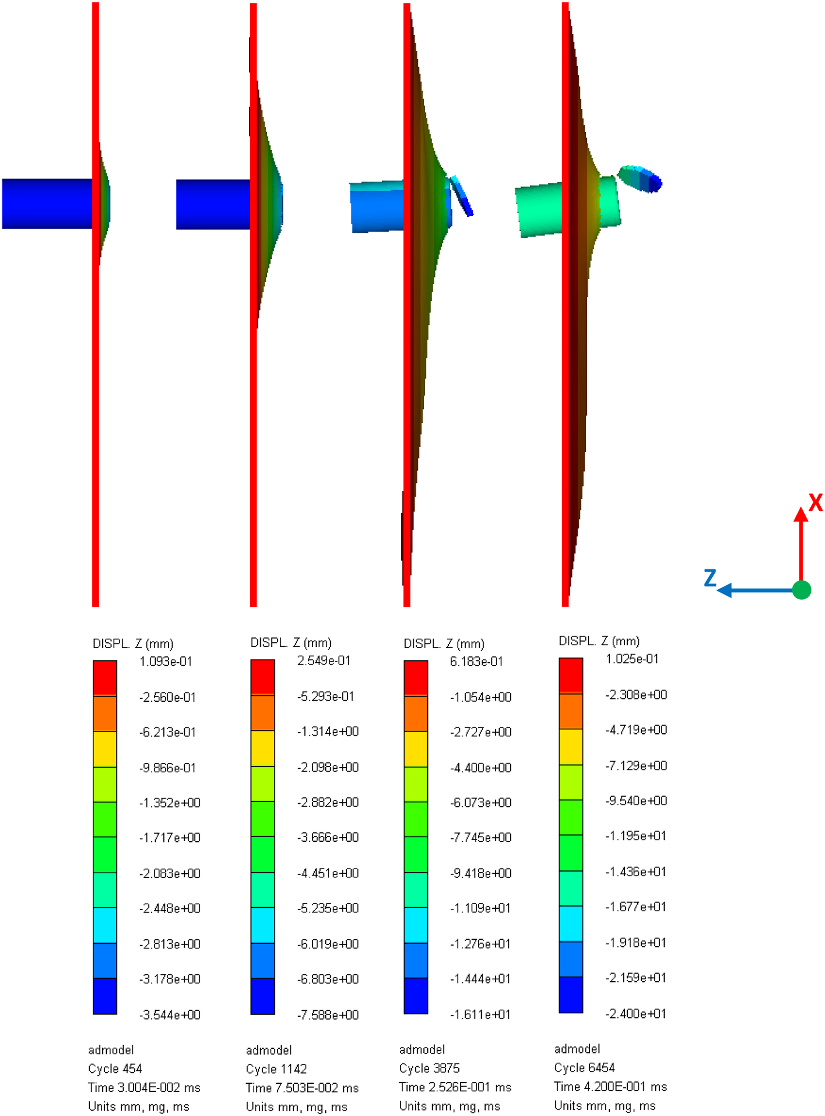
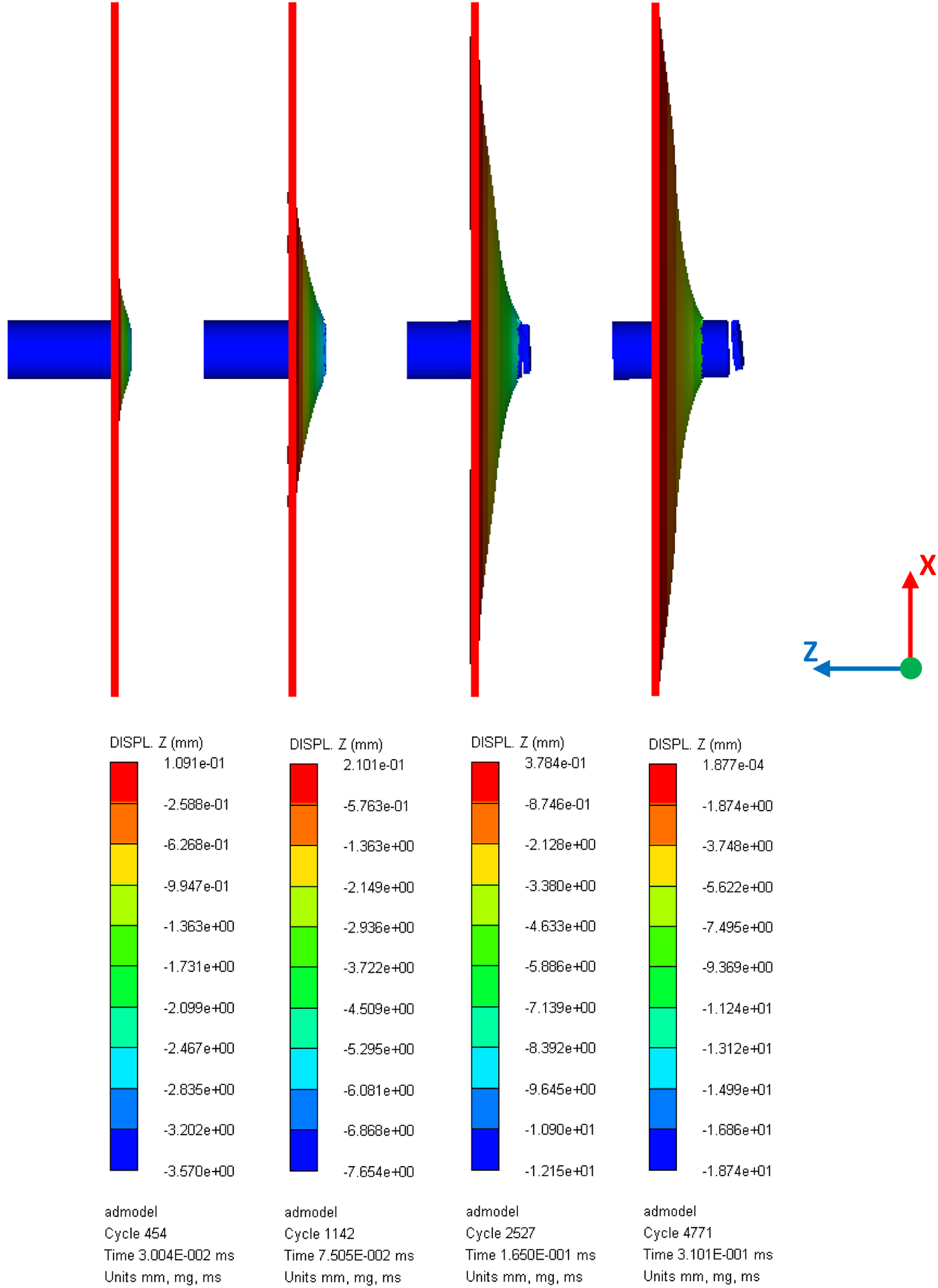
Figure 7 illustrates the evolution of the Z-displacements of a clamped aluminum plate subjected to eccentric impact (case 3) by the cylindrical projectile with the ballistic limit velocity of 117 m/s. The first snapshot of Figure 7 illustrates the localized deformation of the plate near the circumference of the projectile after the beginning of the impact phenomenon. The second snapshot depicts the more extended deformation of the plate before the beginning of its perforation along with the span of the deformation cone (l c ) measured in the depicted X-Z plane. The third and the fourth snapshots show the Z-displacements of the plate as the impactor perforates the target. Global plate deformations have been developed by the time of 0.24 ms of the third snapshot. It is observed from the last two snapshots of Figure 7 that there is a gradual rotation of the projectile. The failure mechanism illustrated in Figure 7 is plugging caused mainly by shear. The plug separation initiates from the side located near the clamped edge of the plate. The rotation of the projectile is mainly attributed to the asymmetry of the plug separation.
Figures 8 and 9 illustrate the evolution of the Z-displacements of a clamped aluminum plate impacted eccentrically (case 2) and centrally (case 1) by the rigid projectile with the ballistic limit velocity of 127 m/s and 128 m/s, respectively. The snapshots presented in these figures depict the same characteristic stages as in Figure 7. It is noted that the failure mechanism of plugging principally due to shear is observed in all depicted cases of the present subsection. Plug ejection has been also reported in experimental 32 and analytical studies 26 as the main failure mode of plates impacted normally by flat-faced projectiles.
In Figure 8 a slightly assymetric plug separation is depicted along with the subsequent gradual rotation of the striker. A practically symmetric plug separation is observed in Figure 9 along with a negligible rotation of the projectile after the perforation of the panel. As expected, the deformations around the projectile in Figure 9 are practically symmetric about the centre of the plate, which is a basic difference in comparison with the eccentric impact cases of Figures 7 and 8. The symmetry of the deformations and plug separation in Figure 9 results in the observed translational motion of the projectile with negligible rotation.
Figures 10–12 illustrate the side view of the Z-displacement contours at the aforementioned characteristic stages for aluminum panels with mixed bc impacted by the cylindrical projectile with the predicted ballistic limit velocities. More specifically, in Figures 10 and 11 Side view of Z-displacement contours of an aluminum panel with mixed bc impacted eccentrically (case 3) by a rigid projectile at characteristic stages during the impact phenomenon. Side view of Z-displacement contours of an aluminum panel with mixed bc impacted eccentrically (case 2) by a rigid projectile at characteristic stages during the impact phenomenon. Side view of Z-displacement contours of an aluminum panel with mixed bc impacted centrally (case 1) by a rigid projectile at characteristic stages during the impact phenomenon.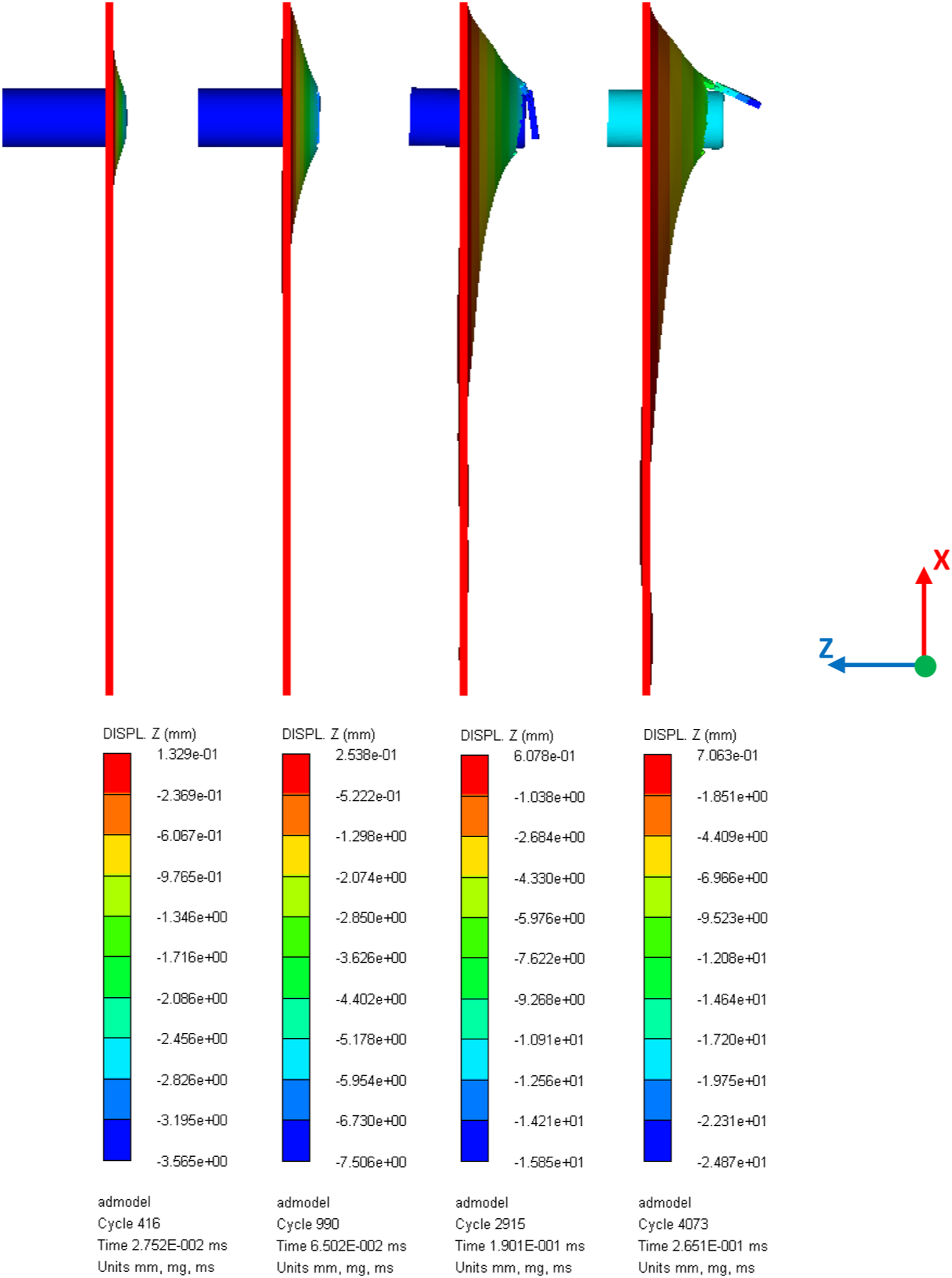
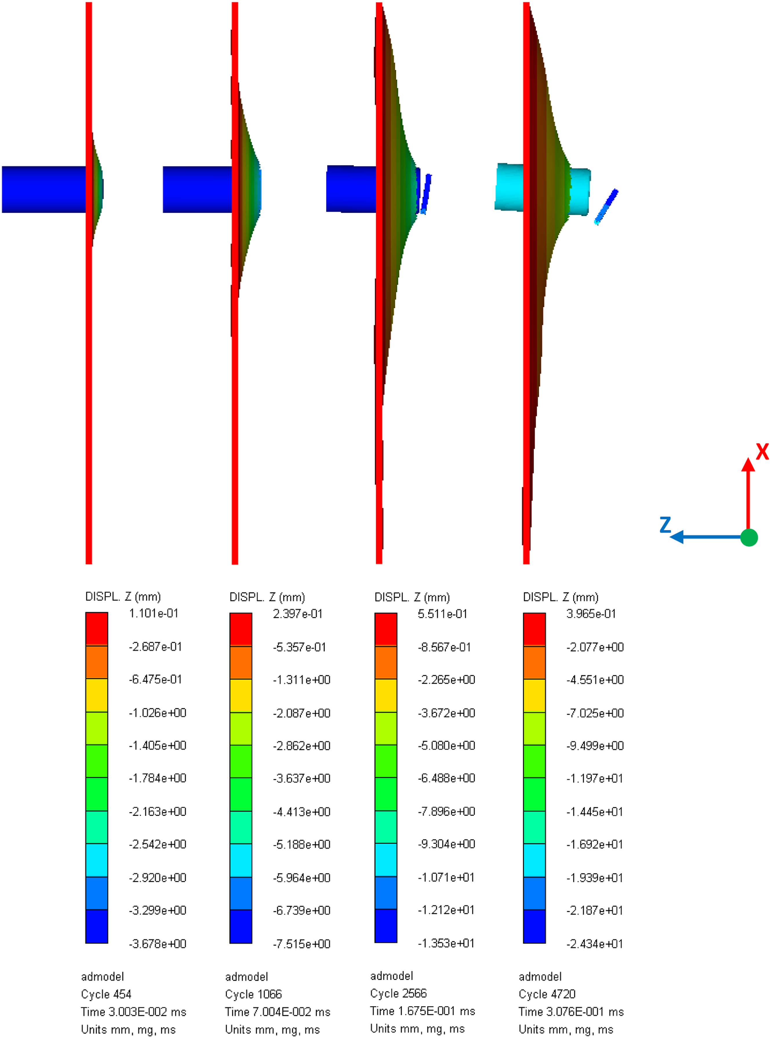
In the study of Phoenix and Porwal 26 the importance of the growing deformation cone of the target during the impact phenomenon is demonstrated. Considering the central impact cases with clamped and mixed bc, it is observed from Figures 9 and 12, respectively, that the deformation cone in the depicted X-Z plane is practically symmetric with respect to the normal axis (Z-direction) passing through impact position 1 (center of the plate). Similarly, it is observed from Figures 8 and 11 that the deformation cone of impact cases 2 is practically symmetric before the beginning of the perforation for both bc with respect to the normal axis passing through impact position 2 (shown in Figure 1). On the contrary, this is not valid for any of the examined bc in impact cases 3 (Figures 7 and 10).
It is observed from Figures 7 and 10 that the growth of the deformation cone is substantially affected by the type of bc when high eccentricity of the impact point is considered. A substantial variation of the cone angle is observed from Figure 10 (mixed bc), at the side located near the simply supported boundary, whereas this is not observed in Figure 7 (clamped bc). The substantial effect of different bc when high eccentricity is considered is also reflected on the different projectile’s trajectory observed in Figures 7 and 10, with significant and negligible rotation, respectively.
It can be observed from the second snapshot of Figures 7–12 that before the beginning of the perforation, l c is slighlty lower in impact case 3 than in impact cases 1 and 2, for both bc types. This is attributed to the fact that when the eccentricity is high the span is limited by the bc.
Ballistic limit and minimum perforation energy
In Figure 13 the ballistic limits of the monolithic aluminum and GLARE 5-2/1-0.5 panels, which have been calculated as described in section Numerical modeling procedure, are compared. It is observed from this figure that the ballistic limit of each target can be substantially affected by increased eccentricity of the impact point (cases 3 and 4), for both of the examined bc types. However, for relatively lower distances of the impact point from the centre of the plate (cases 2 and 5), the ballistic limit of both materials is not much affected by the eccentricity, for the examined bc types. It can also be observed from Figure 13 that GLARE 5-2/1-0.5 panels (thickness 0.152 cm) have higher ballistic limits in comparison with aluminum panels (thickness 0.16 cm) for each impact case and bc type. This finding demonstrates the excellent impact performance of GLARE 5 panels mentioned in the introduction of this study. Ballistic limits of aluminum and GLARE panels with clamped (C) and mixed (M) bc for each of the five positions of the projectile impact.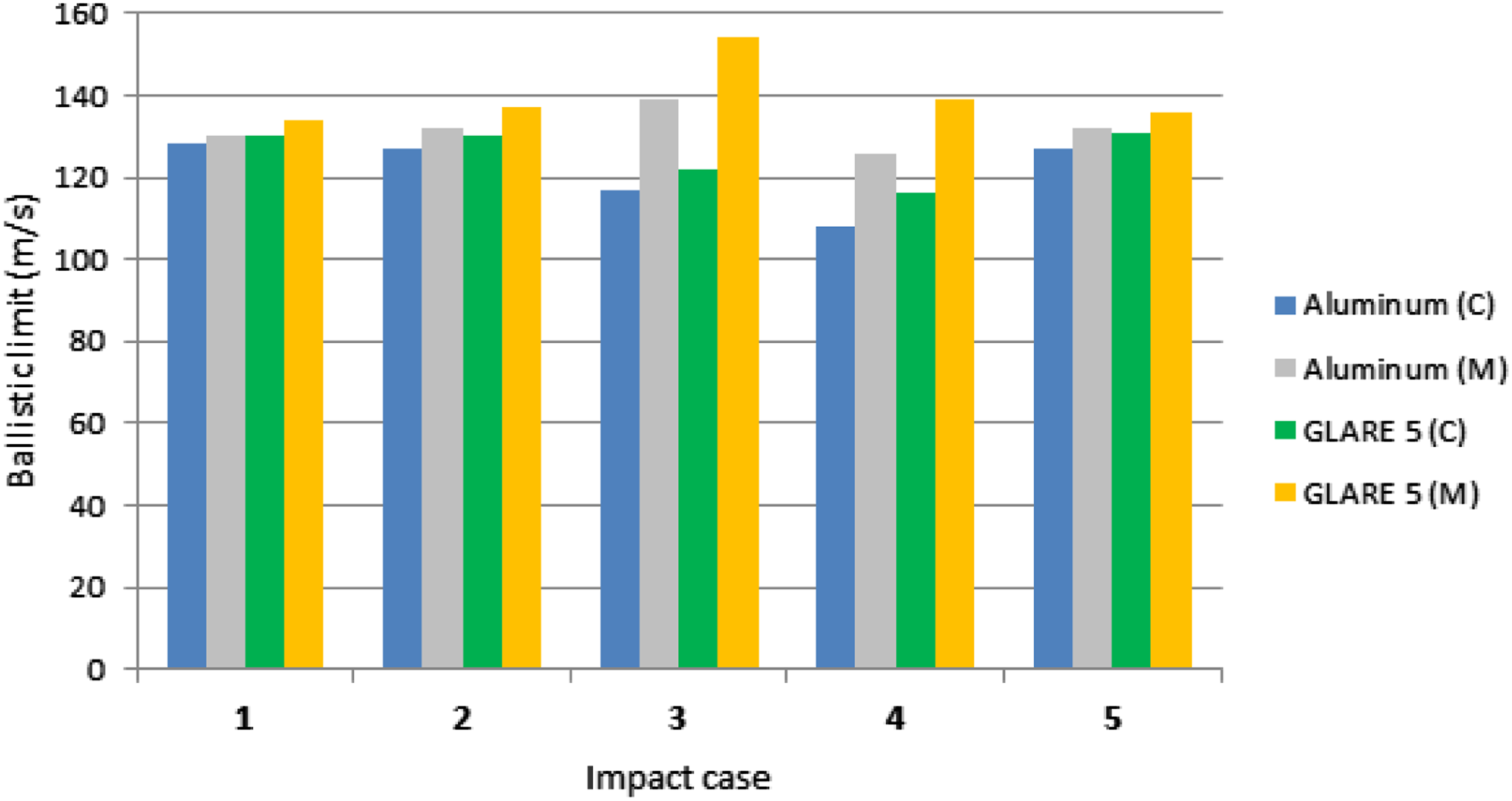
It is shown from Figure 13 that for each impact case, mixed bc result in higher ballistic limits than clamped bc, for both materials. It is also shown that as the eccentricity increases the ballistic limits are affected differently for each support type. For example, the ballistic limit of impact case 3 of a GLARE 5 panel with clamped bc is lower than the corresponding ballistic limit of the central impact. On the contrary, the ballistic limit of case 3 of the same panel with mixed bc is higher than the corresponding central ballistic limit. These findings indicate the considerable influence of the bc on the ballistic impact performance of aluminum and FML plates, when the eccentricity of impact is considered.
It is valuable in impact engineering calculations to know the minimum perforation energy of a target. For this reason, in Figure 14 the ballistic limit impact energies of the striker corresponding to the predicted ballistic limit velocities of Figure 13 are given. The variations among the ballistic limits of Figure 13 are reflected to the variations among the perforation energies of Figure 14. But the variations in Figure 14 are augmented due to the squared value of velocity in the striker’s kinetic energy formula.
28
Referring to the same impact case and constituent material of the target, it is clear from Figure 14 that the panels supported with mixed bc have higher perforation energies than those supported with clamped bc. This finding is mainly attributed to the fact that the two simply supported edges of the mixed bc allow greater localized and global deformation of the target. Global and local panel deformation are basic impact energy absorption mechanisms.13,19,28 Consequently, greater amount of impact energy must be consumed to defeat these mechanisms in the case of mixed bc, a factor that increases the required perforation energy. Ballistic limit impact energies for aluminum and GLARE panels with clamped (C) and mixed (M) bc for each of the five positions of the projectile impact.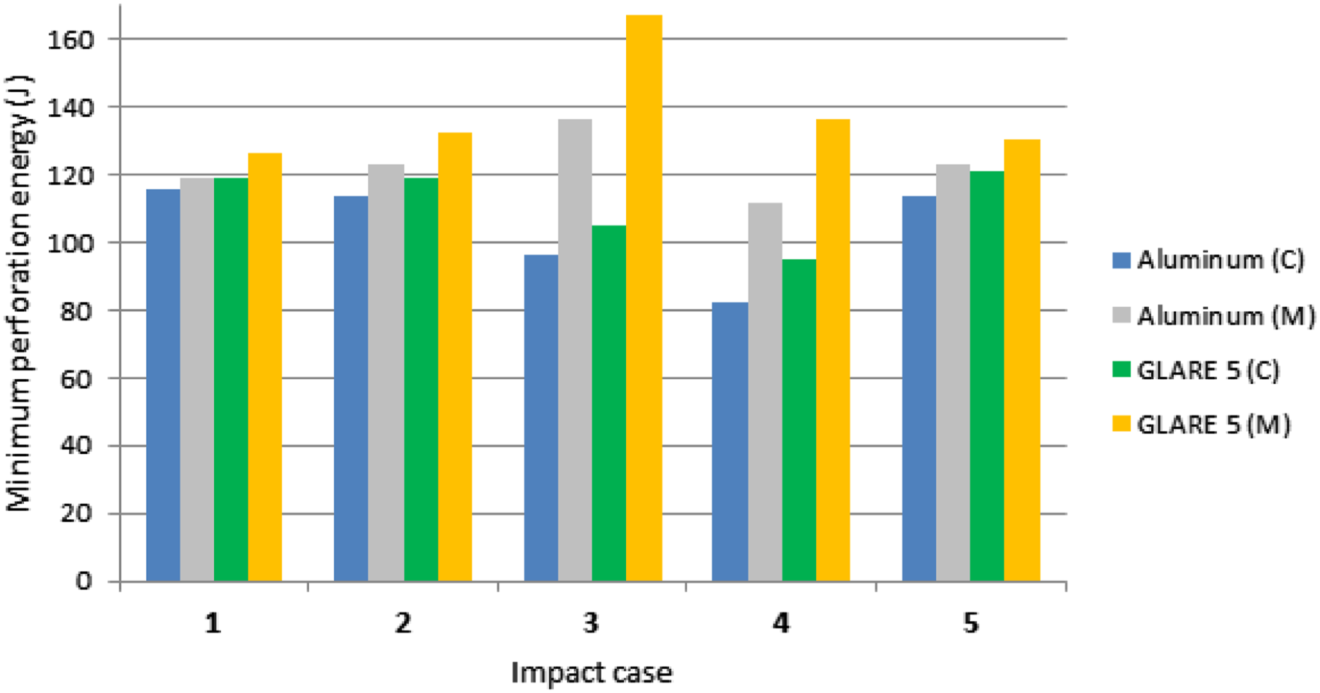
It is observed from Figure 14 that the variation of the perforation energy corresponding to the same target supported with the two types of bc is considerably higher at the impact points with the longest eccentric distance (cases 3 and 4), due to the effect of different bc. As illustrated in Figure 14, for both of the considered materials the maximum values of perforation energy are predicted for case 3 when the plate is supported with mixed bc. It is also interesting to notice that for both aluminum and GLARE plates supported with mixed bc the perforation energies of case 4, which has the longest eccentric distance, are substantially lower than the maximum values of case 3. This is mainly attributed to the fact that impact case 3 allows greater global and local panel deformation than impact case 4 which is closer to the clamped edge.
An important observation from Figures 13 and 14 is that at each of the five impact positions, the ballistic limits and minimum perforation energies satisfy the following inequalities: RGM > RAM ≥ RGC > RAC. The symbol R stands for the ballistic resistance of the panel which is measured using either its ballistic limit or its minimum perforation energy. The symbols RGM, RAM, RGC and RAC correspond to the ballistic resistance of GLARE with mixed bc, aluminum with mixed bc, GLARE with clamped bc and aluminum with clamped bc, respectively. Consequently, it is found that GLARE panels with mixed bc offer the highest ballistic resistance whereas aluminum panels with clamped bc offer the lowest ballistic resistance, regardless of the impact position.
In Figures 15 and 16 the effect of the impact point eccentricity on the ballistic limits and minimum perforation energies, respectively, is depicted for the considered panels with clamped bc. The depicted quadratic polynomial curves in these figures interpolate the predicted data points. The eccentric distance is measured along the X-axis and along the diagonal of the square plate shown in Figure 1. It is observed from Figures 15 and 16 that the depicted trend of the curves is mainly affected by the direction of eccentricity: GLARE and aluminum curves corresponding to the same eccentricity direction (diagonal or X-axis direction) have a similar trend versus the distance from the centre of the plate. Ballistic limits of aluminum and GLARE panels with clamped bc as a function of the impact point eccentricity. Ballistic limit impact energies for aluminum and GLARE panels with clamped bc as a function of the impact point eccentricity.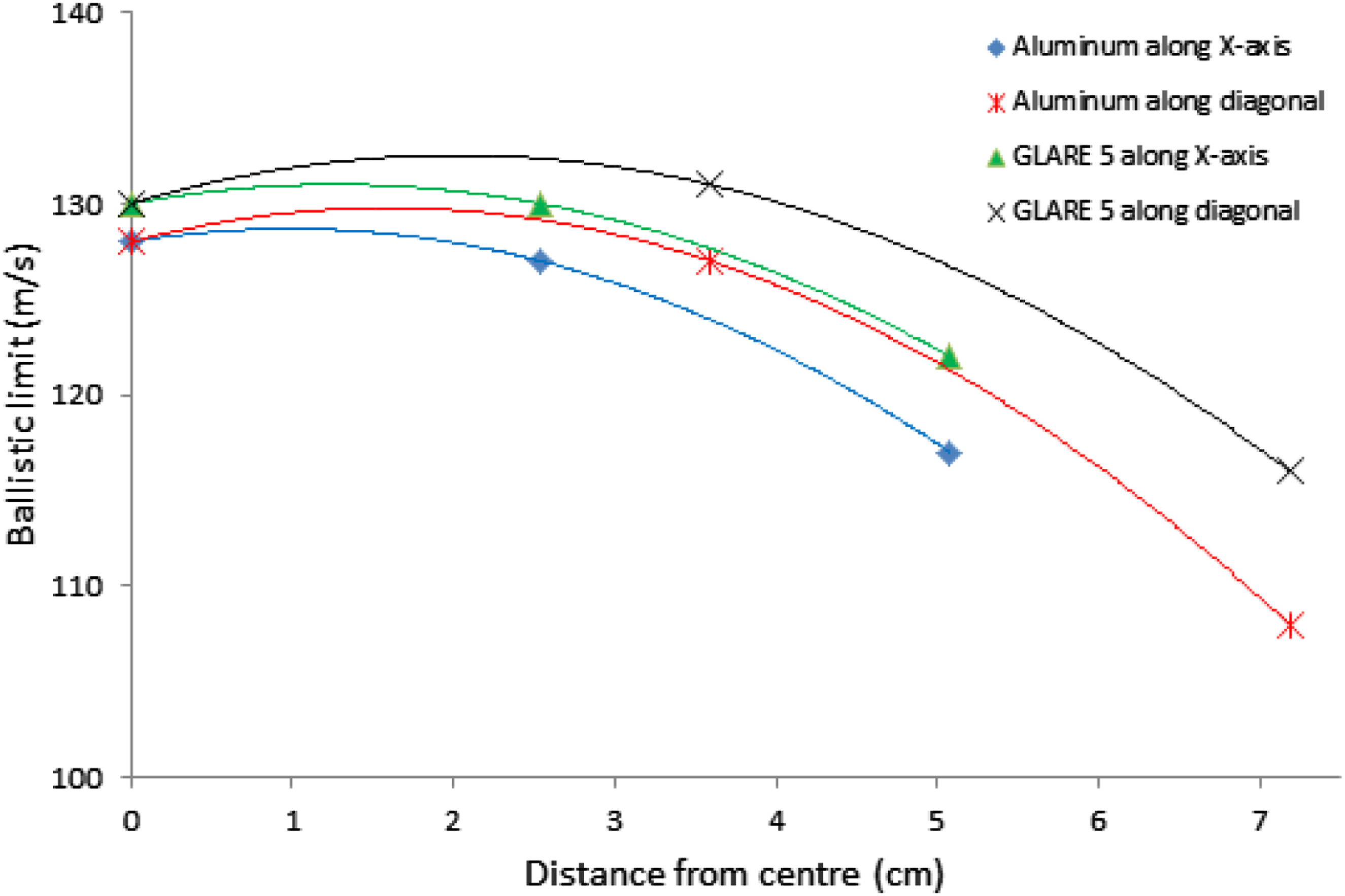
It is observed from Figure 16 that the lowest perforation energies of both materials are predicted for the maximum eccentric distance of 7.18 cm and are substantially lower than those corresponding to the eccentric distance of 5.08 cm. This finding is mainly attributed to the proximity of impact case 4 to the clamped edges of the plate which restrict the global and local panel deformation, two previously discussed basic impact energy absorption mechanisms. The impact energy consumed to defeat these mechanisms is now minimized, a factor that reduces the required perforation energy.
Using the quadratic polynomial curves of Figures 15 and 16, the eccentric distance from the centre of the plate where the ballistic limit and the corresponding perforation energy are reduced considerably, by 5% in comparison with impact case 1, can be estimated. It is found that the ballistic limit of aluminum drops to 121.6 m/s at a distance of 3.29 d measured along the X-axis and 3.95 d measured along the diagonal, where d is the projectile’s diameter. The ballistic limit of GLARE becomes 123.5 m/s at a distance 3.74 d measured along the X-axis and 4.60 d measured along the diagonal. The perforation energy of aluminum drops to 109.6 J at a distance of 2.66 d measured along the X-axis and 3.40 d measured along the diagonal. The perforation energy of GLARE becomes 113.0 J at a distance of 3.09 d measured along the X-axis and 4.04 d measured along the diagonal. These estimations provide a useful reference for the design of impact-resistant structures.
Figure 17 illustrates the evolution of the Z-displacement contours for two clamped GLARE 5 panels impacted centrally (case 1, Figure 17(a)) and eccentrically (case 4, Figure 17(b)) by the rigid projectile. The three snapshots of Figure 17(a) and (b) depict the growing deformations of the target, from the beginning of the impact phenomenon (first snapshot) until the time just before the initiation of perforation (third snapshot). It is observed from the first snapshot that for approximately equal maximum Z-displacement the out-of-plane deformation shape of the target is similar for the two impact cases. The second snapshot shows that even though the maximum Z-displacement of the plate is again practically equal for the two cases, the deformation shape has become different for the eccentric impact since it has now been affected by the bc near the impact point. It is observed from the third snapshot of Figure 17(a) and (b) that the maximum Z-displacement of the central impact just before perforation is greater than that of the eccentric impact (case 4). It is also obvious from the same snapshot that the out-of-plane deformations are more extended in impact case 1 in comparison with case 4. This is attributed to the bc near the impact point which restrict the out-of-plane deformation of the plate more in impact case 4. Consequently, greater local and more extended global deformations of the clamped target have been developed during the central impact in comparison with the eccentric one before its perforation begins. Thus, greater amount of impact energy must be consumed in the case of central impact to deform the target up to this stage, a factor that increases the ballistic limit velocity in comparison with impact case 4. Evolution of Z-displacement contours (back view) of a clamped GLARE 5 panel impacted (a) centrally (case 1) and (b) eccentrically (case 4) by a rigid projectile.
In Figure 18 Z-component of projectile’s velocity time histories along with the point indicating the beginning of perforation for clamped GLARE 5 panels impacted centrally and eccentrically (case 4) by the rigid projectile.
Conclusions
The present article deals with the eccentric ballistic impact performance of square fiber-metal laminates and monolithic aluminum plates impacted normally by a rigid cylindrical free-flying projectile. The ballistic impact phenomenon on GLARE 5-2/1-0.5 FMLs and 2024-T3 aluminum targets is simulated with the ANSYS AUTODYN hydrocode. The numerical modeling procedure is based on the finite difference method and is validated mainly through comparisons of the numerically predicted ballistic limits of the targets with corresponding published experimental values.
Using the validated numerical models, five different impact points on the panel surface are considered in order to investigate the effect of their eccentricity on the ballistic impact performance of the analyzed materials. Clamped and mixed bc are studied for the considered impact cases.
It is found that the mixed bc increase the ballistic impact resistance of the targets, especially when the impact point is near the edges of the plate.
The variations of ballistic limit and minimum perforation energy as a function of the eccentric distance of impact point depend on the direction of eccentricity and the constituent material of the target. However, it is estimated that for the impacts on the clamped aluminum and GLARE 5 targets with eccentricity less than 3.29 d, the ballistic limit will not deviate more than 5% from its central impact value. Similarly, for eccentricity less than 2.66 d, the minimum perforation energy will not deviate more than 5% from its central impact value.
The ballistic resistance of the targets at each impact point satisfies the following inequalities: RGM > RAM ≥ RGC > RAC. Consequently, it is found that GLARE 5 panels with mixed bc offer the highest ballistic resistance whereas aluminum panels with clamped bc offer the lowest ballistic resistance.
The results of the present numerical study will contribute to the research and development of impact resistant aluminum and FML structures when the eccentricity of projectile impact is considered. The contribution is even more significant in the aerospace structural design, since these materials are widely used in the aerospace industry. Furthermore, the results elucidate the effect of different target’s bc on the eccentric ballistic impact performance. The fact that the different bc examined in this article are classical idealizations of real supporting structures increases the practical implications of the results.
Footnotes
Declaration of conflicting interests
The author(s) declared no potential conflicts of interest with respect to the research, authorship, and/or publication of this article.
Funding
The author(s) received no financial support for the research, authorship, and/or publication of this article.
Data availability statement
Data sharing not applicable to this article as no datasets were generated or analyzed during the current study.