
Abstract
This paper investigates the phenomenon of high-velocity impact on a lightweight composite sandwich panel comprising of autoclaved aerated concrete (AAC) core and fiber metal laminate (FML) face skins. These experimental trials were explicitly designed to ascertain the ballistic limit velocity (BLV) of FML reinforced AAC subjecting to impact loading of a rigid flat-nosed projectile. In conjunction with experimental investigations, an analytical model based on closed-form solutions employing energy equations was meticulously developed to offer a deeper analysis of the impact event. This analysis encompassed the identification of various damage mechanisms that manifest during high-velocity impacts, including core crushing, tensile fracture, fiber breakage, delamination, plugging and the formation of petals. Furthermore, a sensitivity analysis using dimensionless variables was employed to provide a more profound insight into the influence of diverse parameters such as the mass and initial velocity of the projectile. Additionally, three-dimensional finite element method (3D FEM) simulations via the Ls-Dyna package were carried out to estimate the effects of various projectile nose shapes on ballistic performance, failure modes, energy absorption (EA), and specific energy absorption (SEA) of the target. The simulations revealed that the projectile nose shape can induce various damage mechanisms within the FMLRAAC panel. During the impact process, the E glass/epoxy composite layer undergo matrix cracking, fiber breakage occurred along with delamination, and consequently, the Al skin underwent plastic deformations until this layer fractured permanently at the impact position. As a result insulating AAC in a sandwich structure between two FML face skins reproduce a significant strength and stability. Moreover, the manufacturing of FMLRAAC in construction is a simple process to promote its structural capability especially for hazardous environment as load bearing structural material.
Keywords
Introduction
Lightweight structures composed of composite sandwich panels find extensive applications across diverse industries, including aerospace, maritime, automotive, and construction. Over their operational lifespan, these structures are subjected to a range of loading conditions, including localized low and high-velocity projectile impacts. 1 While these structures may not be explicitly designed as protective or shielding barriers with the primary aim of withstanding sudden impacts from foreign objects or ballistic threats, it remains imperative to conduct comprehensive investigations into their failure modes and ultimate strength. Consequently, these impacts lead to a notable diminishment in both the structural strength and stiffness, manifesting in both external and internal aspects of the structure. Hence, it becomes imperative to actively develop and refine novel strategies and designs aimed at enhancing the impact resistance of existing and future structures. Given their inherent vulnerability to the aforementioned impact scenarios, devising methods to mitigate the resultant damages assumes paramount significance, not only for the well-being of occupants but also for the preservation of structural integrity.
An effective safeguard against high-energy impacts necessitates a meticulous approach to both design and manufacturing processes. Sandwich panels featuring low-density cores have garnered notable attention as versatile structural elements. 2 These structures, in general, exhibit a heightened susceptibility to damage caused by impacts. This heightened vulnerability arises from the abrupt nature of impact events, wherein the load amplitude can exceed the static equivalent load by several orders of magnitude. 3 The selection of materials for sandwich structures is contingent upon several factors, including the intended function of the structure, anticipated service life, material availability, and cost considerations. Within the construction industry, a prevalent configuration for composite sandwich structures involves the incorporation of a lightweight core element, positioned between upper and lower face sheets. 4
The design of sandwich cores offers a wide spectrum of possibilities, encompassing configurations such as honeycomb, 5 cementitious, 6 metallic, 7 and synthetic foams, 8 as well as lattice 9 and truss designs, 10 often augmented by options for corrugation and/or pin reinforcement.11,12 Within composite sandwich structures, the upper and lower face sheets serve a pivotal role by functioning as protective layers against external loads. Composite sandwich panels are associated with a variety of face sheet materials, as documented in numerous sources. These materials encompass wood, metals, polymers, and even combinations of two or more materials, such as functionally graded materials (FGM) or fiber metal laminates (FMLs).13–17 Notably, research has demonstrated the efficacy of a composite sandwich panel configuration featuring a lightweight core paired with a rigid face sheet, providing robust protection against fire, blast, and impact loads. 18 Autoclaved aerated concrete (AAC) stands as a prevalent cementitious cellular lightweight material extensively employed within the construction industry. Distinguished from conventional concrete, AAC exhibits a markedly lower density and exceptional insulation characteristics. 19 It features a discontinuous pore structure, comprising nearly 80% air-pores, thereby rendering it a low-density material with inherent limitations in terms of compressive and impact strength. 20 Hence, it becomes imperative to address the vulnerability of such low-strength materials when subjected to localized impact loads. To date, numerous hybridization techniques have been rigorously examined with the aim of enhancing the ballistic resistance of these materials. Such techniques include the advancement of composite laminates featuring ceramic facings for use as armor shields,21,22 the innovation of high-strength lightweight fibers, and the development of multifunctional hybrid structures through the interleaving of brittle and ductile material layers23,24 organized with meticulous consideration of stack arrangement.
FMLs represent a class of multifunctional hybrid lightweight materials, characterized by their composition of alternating layers comprising thin metallic sheets and fiber-reinforced composites. FMLs offer a noteworthy amalgamation of the advantageous attributes found in monolithic metals and fiber-reinforced composites, resulting in substantially enhanced mechanical properties. 25 In the realm of engineering design for these materials, the overarching objective is to synergistically harness the superior qualities inherent in both metals and fiber-reinforced composites. The advancements achieved through the FML concept have served as a catalyst for the authors’ exploration into proposing a composite sandwich panel by insulating AAC blocks between two FML skins. In the past decade, the investigation of the quasi static mechanical and impact response of AAC/FRP sandwich structures has been the focus of some studies along with analytical 26 and numerical 27 investigations. Numerical simulation when contrasted with analytical approaches, it proves especially advantageous for modeling complex structures and boundary conditions, enabling a more faithful representation of stress distribution and damage progression. Several studies have delved into the numerical analysis of the impact response exhibited by composite sandwich panels, affirming the critical role of the finite element method in investigating the dynamic interactions of foreign objects with sandwich structures. Notably, the modeling of damage within both face-sheets and core materials stands as a pivotal element in analysis of impact events. One notable examination involved the evaluation of the response of AAC/CFRP sandwich structures to low-velocity impact, conducted by Serrano-Perez et al. 28 In their study, they conducted a comparative analysis between experimental results and predicted energy absorption values, as determined by an energy balance model. Dey et al. 29 conducted a comprehensive study on the impact response of fiber-reinforced AAC, employing a three-point bending configuration facilitated by a specially instrumented impact device. In a separate investigation, Li et al. 30 assessed the performance of AAC masonry walls when exposed to vented gas explosions. Bayat et al. 31 conducted an experimental investigation involving quasi-static three-point bending and indentation tests on autoclaved aerated concrete reinforced with both glass fiber and FML. Their findings revealed a substantial enhancement in the mechanical performance of FML reinforced AAC, with improvements of up to 300% compared to plain AAC. By adopting this methodology, the inherent properties of each constituent component contribute synergistically to bestow the entire assembly with an exceptional stiffness-to-weight ratio.
The present study delves into the high-velocity impact behavior of a hybrid composite sandwich panel with an AAC core, insulated with FML skins comprising thin aluminum plates and thermoset E/Glass composite face sheets. To assess the impact performance of the hybrid composite sandwich panel, manufactured specimens were subjected to high-velocity impact using a rigid flat-nosed projectile launched from a gas gun apparatus. Visual observations of the tested samples facilitated the construction of a three-stage damage progression model, which aligned with a comprehensive five-stage energy transformation process. This model was instrumental in validating the analytical and numerical model implemented in LS-DYNA FE Package. The analytical approach based on energy method was employed to providing a more profound insight into the influence of diverse parameters such as the mass and initial velocity of the projectile. Subsequently, FE models were employed to scrutinize the perforation process, with a particular emphasis on the influence of projectile nose shape diversity on factors including failure modes, energy absorption (EA), SEA, and residual velocity of the projectiles.
Experimental procedure
Specimen
The composite sandwich panels were meticulously crafted through a hand lay-up process, followed by a curing procedure that involved the application of pressure. The pressurization step served the dual purpose of expelling excess resin and minimizing the presence of air voids within the panels. For an illustrative representation of the geometrical details and the sample lay-up configuration of the FMLRAAC composite sandwich panel is depicted in Figure 1. Lay-up configuration and dimensions of the proposed cubic composite sandwich panel.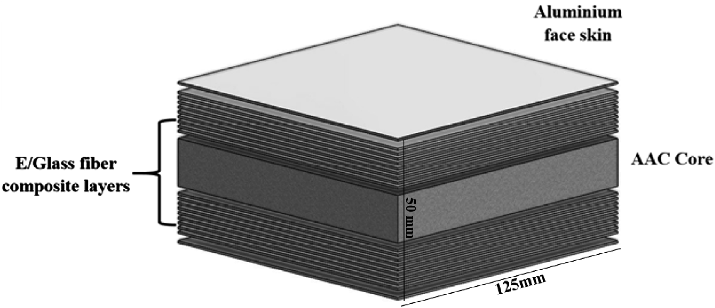
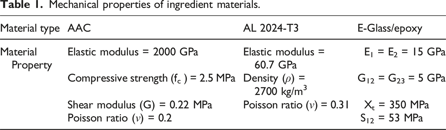
Mechanical properties of ingredient materials.
Impact test
The impact testing arrangement, as depicted in Figure 2, comprises a well-equipped laboratory setup inclusive of a gas gun apparatus, high-speed camera, clamped specimen, and chronograph devices. This setup serves as the foundation for conducting high-velocity impact tests. The measurement of both input and residual velocities is facilitated by the deployment of two chronographs, strategically positioned before and after the target fixture. Each chronograph is equipped with a pair of laser beams, enabling the accurate determination of particle velocities within the range of 9 to 2100 m/s, as specified in the equipment datasheet. To mitigate the potential interference caused by small, high-velocity particles dislodged from the target during impact, a cardboard box was strategically positioned behind the chronograph. This precautionary measure effectively prevented these particles from rebounding and subsequently interfering with the chronograph readings.
26
Illustration of impact test configuration: (a) schematic of gas gun apparatus and inside the target chamber (b) High-speed camera and data logger (c) Clamped FMLRAAC target with two square fixtures.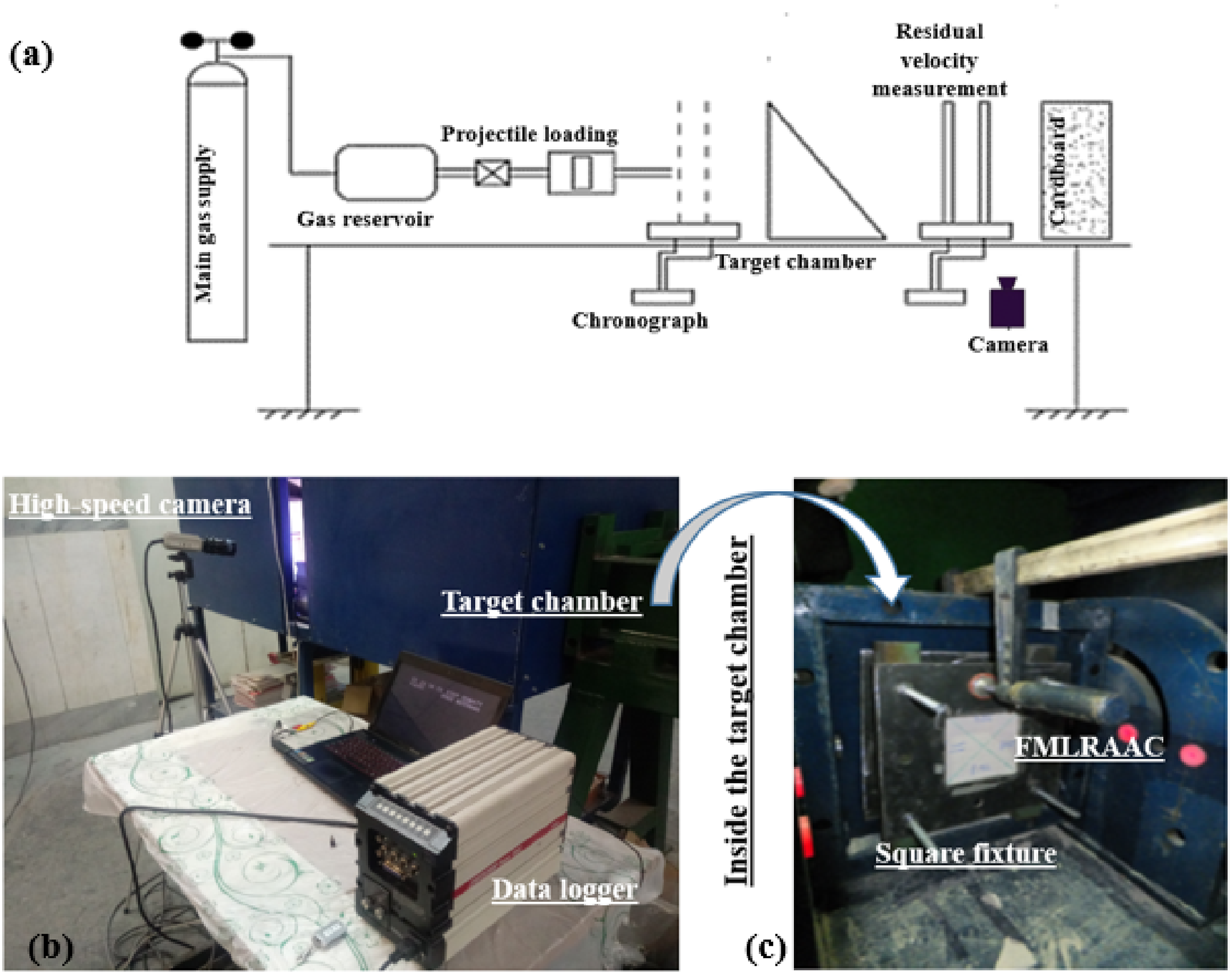
The specimen, on the other hand, was securely clamped along its edges using two steel fixtures characterized by square openings measuring 10 × 10 cm. Subsequently, the clamped specimen was vertically mounted inside the target chamber prior to initiating the gas gun firing sequence. The high-speed camera was strategically positioned perpendicular to the bullet path and within the plane of the target to effectively capture the unfolding impact event subsequent to the interaction between the bullet and the target. The ballistic limit velocity (BLV), representing the minimum impact velocity required to achieve complete perforation, was determined for each FMLRAAC sample by subjecting them to impacts across a range of velocities, spanning from non-perforation to complete perforation. To achieve statistical robustness, 10 test replicated, each featuring identical layup and material properties, were meticulously conducted.
Analytical model
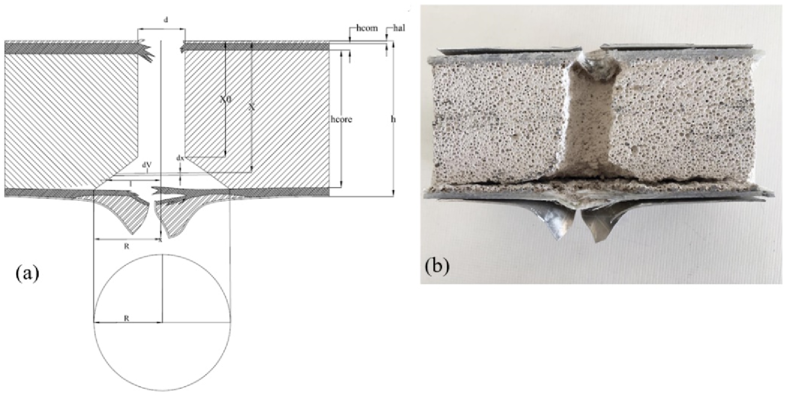
This study introduces an analytical methodology aimed at assessing target perforation in FMLRAAC specimens subjected to the impact of a flat nose projectile. To substantiate the hypothesis that collapse modes primarily correspond to perforation, an analytical solution is derived through the formulation of energy equations. To articulate the analytical formula in this section, a thorough examination of tested specimens led to the identification of distinct energy absorption mechanisms. As illustrated in Figure 3, both a schematic and an actual cross-sectional view of the perforated target are presented. It is imperative to acknowledge that, in this scenario, the presence of FML layers introduces slight modifications to the equations in comparison to plain AAC. Consequently, it becomes necessary to calculate the volume cut for each layer individually. Similar to the plain AAC sample case, the plug assumes the shape of an incomplete cone volume, with the radius at the top (which represents the missing tip section) of the cone approximately equal to the cross-sectional radius of the projectile. The cone angle, as established in prior work of Bayat et al.,
26
was considered to vary within the range of 52 to 32 degrees. They used an analytical model based on energy balance equation considering spatial integration for simplification. While, in this study two terms related to the damage mechanisms of FML layer are added. It is assumed that the kinetic energy of the projectile, denoted as ( • Kinetic energy of the projectile (E
k
) • Crush energy in the core and front plate composite ( • Kinetic energy of plug ( • Tensile failure energy ( • Absorbed energy by friction work ( • Aluminum petal formation in the rear composite plate ( Cross sectional view of the perforated FMLRAAC specimen (a) Schematic and, (b) Real sample; input velocity 403 m/s.
Kinetic energy of the projectile
The differential of energy loss between 
Crushing energy
The methodology for computing the absorbed energy during the crushing process is based on the outcomes of a quasi-static indentation loading test. As illustrated in Figure 4, the stress-strain curve can be discretized into five distinct regions, each representing a distinct penetration process.
31
Among these regions, three deformation modes were discerned within the sandwich panels, namely: localized upper face sheet indentation, core crushing, and localized lower face sheet indentation along with global bending. It is noteworthy that the crushing of the foam core generally transpired prior to the failure of the rear face sheets. Before the ultimate failure of the rear face sheets, a notable phenomenon known as debonding was observed, effectively contributing to energy absorption during the indenter’s penetration. It is worth noting that this phenomenon appears to be contingent upon the bond strength between the FML face skins and the AAC core material. As the indenter progressed, a state was reached wherein tensile stress surpassed the limits of endurance, resulting in the delamination of the E/Glass fiber composite layers and the subsequent separation of the Al skin. Stress-deformation diagram of quasi-static indentation test of FMLRAAC.
31
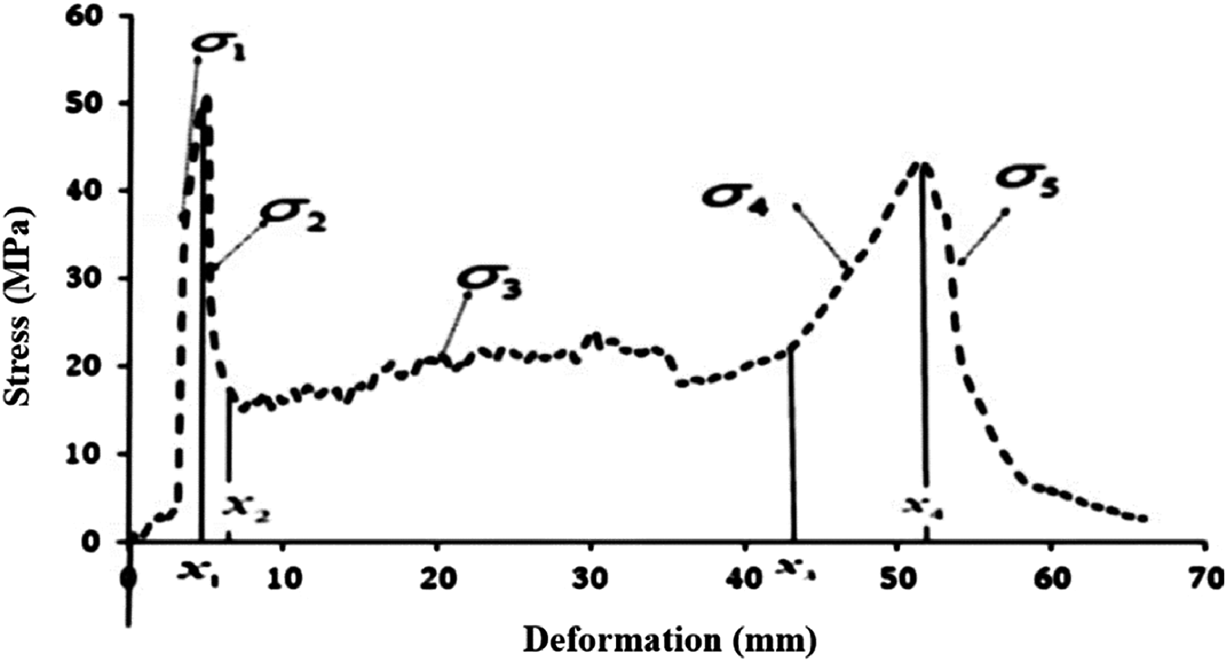
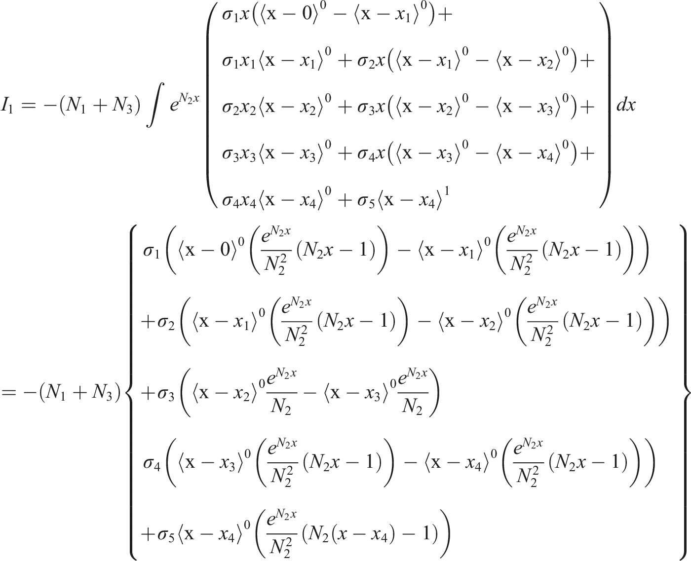
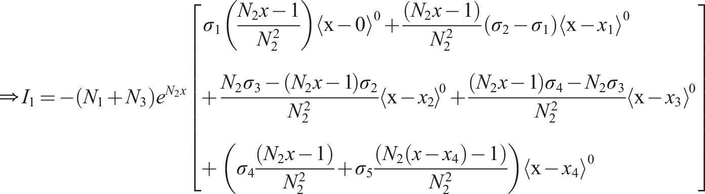
By overlaying the diagram using the Macaulay’s brackets, the stress equation will be as follows: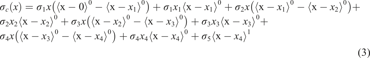
The coefficients are related to the different stress points concerned with phase transitions of diagram. As a result, the amount of energy absorbed by this mechanism could be expressed as follows:
Plug kinetic energy
The kinetic energy of the plug is given by:
Which 
Energy absorbed by friction work
The energy absorbed by the friction work can be calculated as following:
According to reference 33 the effect of friction on composite and aluminum layers can be neglected and only the friction effect for the AAC core is expressed in the calculations.
Energy absorbed by tensile failure
The energy absorbed for variable development by this mechanism is:

As a result, the absorbed energy of the overall tensile failure will be as follows:
Consequently, the relation (11) is obtained for the differential energy absorption by the tensile failure mechanism and can be described for AAC as follows:
To determine the proportion of tensile energy absorbed by the distal composite layer, an analogous procedure is applied, albeit with a variation. This time, the result is represented by an incomplete pyramid rather than an incomplete cone. For clarity, Figure 5 provides a schematic cross-sectional view of the composite layer, excluding the Al skin and the distal face of the specimen, thereby elucidating the formation of the truncated plug composed of glass fiber composite. Schematic of generated truncated petal on the rear composite face sheet after removal of Al skin.
In this case, the following procedure is used to obtain the volume:
In this case 
Petal shear energy in the rear surface
An examination of the perforated rear Al skin reveals that the cutting length spans is twice the length of the projectile plus its diameter, as depicted in Figure 6. Additionally, it is observed that the resulting petals rotate approximately 90 degrees outward. Consequently, the energy associated with the formation of these petals is attributed to a combination of tearing and rotational processes. Plug formation and Al Petalling at the rear side of the FMLRAAC specimen impacted by flat nose shape projectile.
Petal tearing
The energy required to create such a shape is equal to the cross section cut at the rate of first mode energy release.32,33
Petal rotation
The plastic torque per unit length for rotating the cut is equal to:
As a result, the plastic torque of petal rotation around the cut edges is equal to:
The work required to rotate the petal 90 
Consequently, the energy consumed to form the petal mode is equal to
In this case the coefficient 
Equation of motion
Replacing the above four mechanisms in the stability equation the following equation yields:
And by simplifying the equation, it can be rewritten as follows:
Initial condition is defined as follows:
Sensitivity analysis
In order to understand the effect of each parameter, the dimensionless variables are defined as follow:


By applying the relation (25) and (26f) to (23) and (24), the relations (27) and (28) will produce:
Figure 7 presents a sensitivity analysis of energy absorption mechanisms with respect to input velocity, as determined through the model developed in this study. The figure illustrates that at lower initial velocities, the dominant energy absorption mechanisms encompass friction, crushing, petalling, and the tensile fracture energy of the composite. However, their contribution diminishes as velocity increases. Notably, the energy absorbed by the tensile failure of the AAC exhibits the lowest contribution due to its inherently limited tensile strength. Furthermore, the momentum energy coefficient maintains a constant contribution, as it remains independent of velocity. Coefficients R
i
in terms of a function of input velocity related to different energy absorption mechanisms.
Theoretical closed form solution
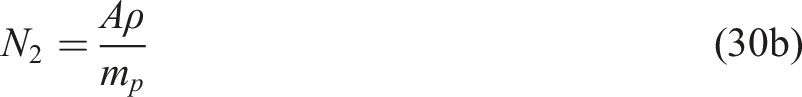
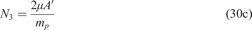
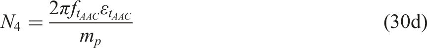
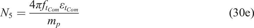
As in the case of the plain AAC sample, in order to achieve a closed form solution by defining constant coefficients in the form of relations (30a) to (30f) and replacing into the relation (27), the following equation (29) reproduced:
The coefficients 
Equation (29) is a first-order differential equation of the form 
Therefore, by deriving the relation (31):

Where the functions 
By applying the initial condition, the constant coefficient C
1
can be obtained as follows:
Numerical approach
Model geometry and mesh
In this section, the objective is to gain a more comprehensive understanding of how different projectile nose shapes affect the impact response of the FMLRAAC panel. This inquiry is pursued through numerical simulations conducted employing the commercial finite element (FE) analysis software, LS-DYNA. It is a versatile non-linear dynamic modeling tool characterized by an explicit formulation, rendering it well-suited for the simulation of impact occasions. The numerical model entails the representation of a rigid flat nose shape projectile with an initial velocity, interacting with a composite sandwich panel featuring FML skins and an AAC core, serving as the target.
As depicted in Figure 8, the numerical model adopted a quarter-symmetry configuration for both the projectile and the target. This approach was chosen to leverage the inherent symmetry in boundary conditions, loading, and the target structure. The sides of the FMLRAAC target were subject to rigid boundary conditions, ensuring that both translational and rotational velocities remained at zero. Visualization of (a) FE model of the clamped target and (b) Magnified meshing of the FMLRAAC.
To ascertain mesh sensitivity and achieve an adequate level of accuracy in capturing stress and deformation, successive space discretization was meticulously performed. The selected mesh configuration comprised a total of 21,600 elements, with 5600 elements allocated to each skin and 16,000 elements designated for the core. Additionally, to optimize software runtime efficiency, the projectile was positioned a mere 0.1 mm away from the target, thereby minimizing computational effort until the moment of projectile impact.
Material model of the target and projectile
Material model parameters of E-Glass/epoxy composite sheets.
Notably, the material model exhibits the capability to predict diverse failure modes intrinsic to fiber-reinforced composite materials. These various failure modes, in accordance with the Chang-Chang failure criteria, have been elucidated in previous sources, such as the LS-DYNA user manual (2019), encompassing tensile and compressive modes denoted by the suffices The table below presents a compilation of symbols elucidating the input parameters for Glass/epoxy material characterization. Specifically, these symbols correspond to various material properties and characteristics, where ‘ρ’ signifies density, ‘E,’ ‘G,’ and ‘ν’ represent Young’s modulus, shear modulus, and Poisson’s ratio, respectively. ‘SC’ denotes the in-plane shear strength, while ‘PARAM’ signifies a parameter associated with damage growth. Additionally, ‘DFAILC,’ ‘DFAILT,’ ‘DFAILM,’ and ‘DFAILS’ respectively denote the failure strain in compression, tension, matrix, and shear modes. Parameters ‘NFLS’ and ‘SFLS’ are indicative of interlaminar tensile and shear strength, while ‘ERATEN’ and ‘ERATES’ pertain to energy release rates in normal (
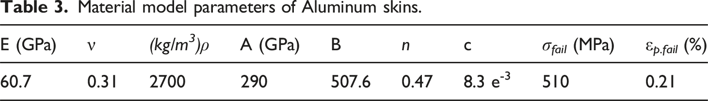
Material model parameters of Aluminum skins.
Material model parameters of AAC core.
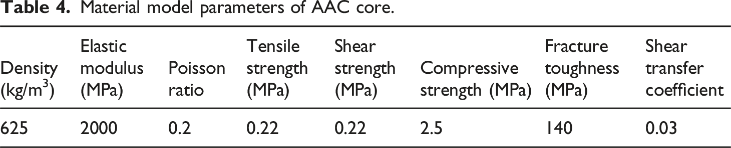
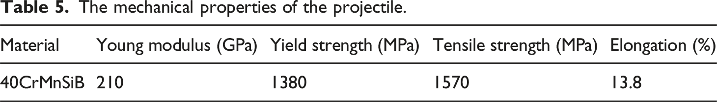
Figure 9 provides a visual representation of the geometries pertaining to various projectiles, while maintaining constant values for mass and diameter. The mechanical properties associated with these projectiles are succinctly summarized in Table 5 which are similar to that utilized in experimental tests. In addition to the flat nose projectile, simulations were conducted using conical, hemispherical, truncated, and ogive nose projectiles. These simulations aimed to facilitate a comparative analysis encompassing deformation processes, failure mechanisms, energy absorption (EA), and specific energy absorption (SEA). To comprehensively analyze the perforation behavior of the impacted FMLRAAC target, this study systematically examines deformation modes and energy dissipation mechanisms. The geometrical and dimensions of the studied various nose shape projectiles in numerical simulation: (1) Flat, (2) Truncated90, (3) Hemispherical, (4) Truncated60, (5) Conical90, (6) Ogive, (7) Conical60. The mechanical properties of the projectile.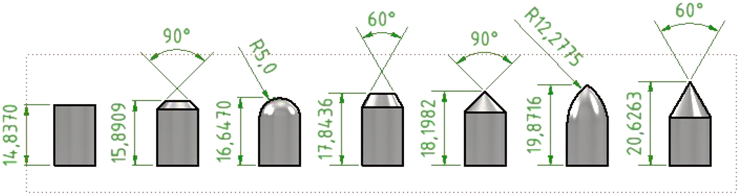
Results and discussion
Experimental
To determine the BLV of the FMLRAAC specimen, a series of 10 impact tests were conducted under experimental conditions. These tests were meticulously replicated to ensure accuracy and reliability. The experimental setup incorporated a chronograph positioned behind the target, responsible for recording the input velocity of the projectile. Concurrently, a high-speed camera was employed to capture the trajectory of the ejecting bullet, as well as its residual velocity, as depicted in Figure 10. Sequential images of the ejected projectile from the rear surface of FMLRAAC specimen, captured by high-speed camera (input velocity 403 m/s).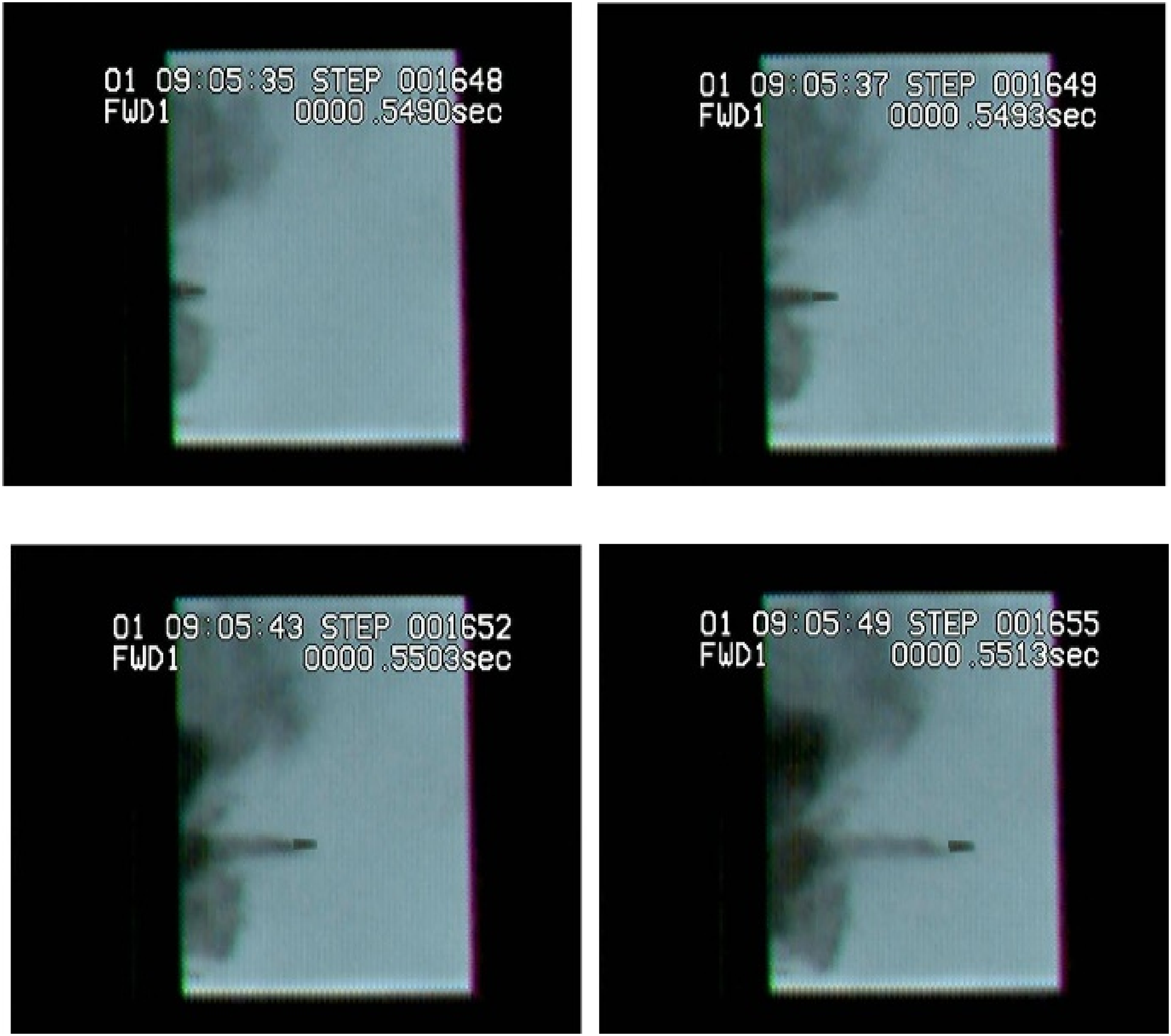
Results of replicated experimental impact tests.
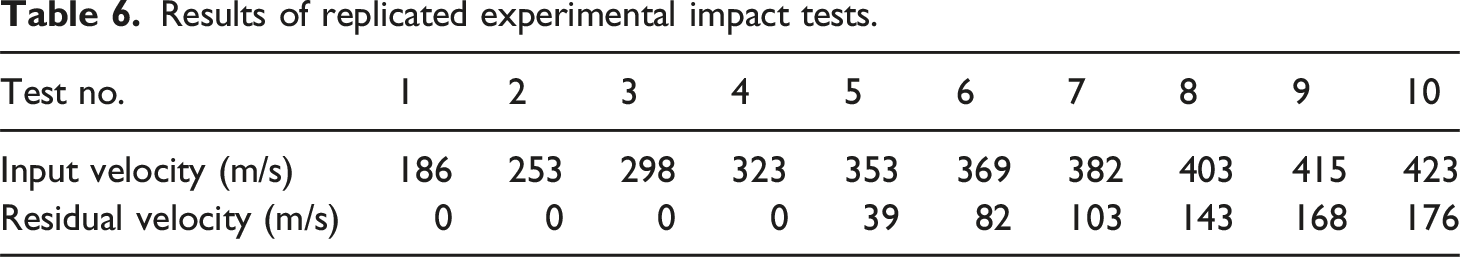
Figure 11 provides a cross-sectional view that allows for a comparative examination of the experimental results and finite element (FE) simulations concerning the tested FMLRAAC specimen. This illustration serves to elucidate the damage patterns and induced deformations. By visually inspecting both the tested specimen and the simulated FMLRAAC, three distinct stages of damage are discerned and subsequently highlighted in the figure. Firstly, the initial stage of damage involves the failure of the front FML face sheet when subjected to the high transverse shear forces imparted by the projectile. This failure manifests in the form of punching, resulting in shear and cutting loading on this layer. Through-sectional view of the perforated FMLRAAC specimen at velocity 403 m/s: (a) Experimental, and (b) Simulation.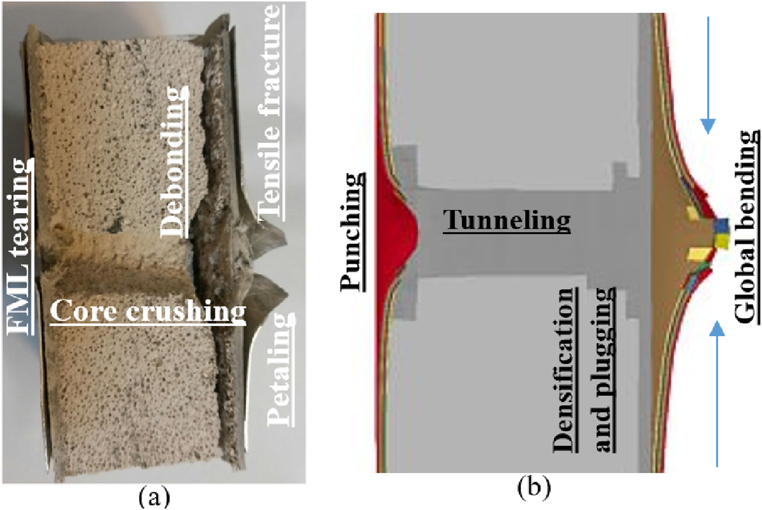
The second stage of the penetration process commences as the projectile advances through the AAC core, effectively creating a tunnel along its trajectory by causing the crushing of the cell walls comprising the core material. As the projectile reached the rear FML surface, a significant densification of the AAC material occurred at the tip of the projectile head, simultaneously leading to the generation of tensile cracks within the core material. The translational motion of the projectile facilitated the acceleration of particles within the AAC block situated in front of the projectile and forming a truncated cone shape. This acceleration, in turn, exerted outward pressure on the rear FML, resulting in the debonding of the core/face sheet interface. In the final stage of this complex process, the bottom face sheet underwent global bending, accompanied by delamination and tensile fracture within the glass/epoxy layers along the path of the projectile. This led to the separation of the aluminum and glass/composite layers, ultimately forming a distinctive petal shape.
Notably, the sheared plug, located approximately at the head of the projectile, and the sharp failed edges, attributed to a dishing mode. Ultimately, as the projectile lost contact with the target material, it continued its trajectory at a constant residual velocity. The striking similarity between the predicted damage surfaces and the observed ones confirms the validity and accuracy of the finite element model in reproducing all the observed damage phenomena. To further assess the concordance between the analytical model and FE predictions vis-à-vis the experimental results, a comparison of the predicted and measured residual velocities can be undertaken.
Analytical results
Model verification
To validate the analytical formula derived in this study, a series of impact experiments were meticulously conducted. These experiments involved the use of a rigid flat projectile, with velocities spanning from 180 m/s to 450 m/s. The resultant data is depicted in Figure 12, which graphically represents the residual velocities in relation to the initial projectile velocity. Evidently, there exists a discernible and reasonable correlation between the analytical predictions and the experimental values. This outcome underscores the capacity of the proposed analytical model to accurately predict the BLV with an error margin of less than 20%. Obtained residual velocity from experimental tests vs. analytical prediction.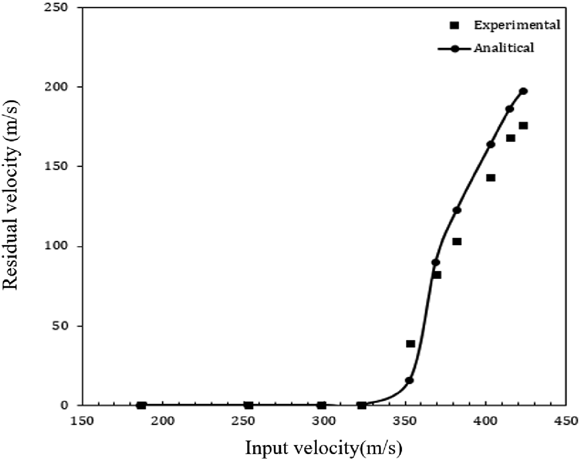
Figure 13 presents a comprehensive breakdown of the dimensionless energy absorption mechanisms, derived from the developed analytical model, across varying initial projectile velocities. Notably, in the case of AAC, an increase in the initial projectile velocity results in a corresponding increase in the contribution of the momentum absorption mechanism. At higher velocities, this contribution becomes notably dominant. Contribution of various energy dissipation mechanisms versus different input velocities.
Intriguingly, the energy absorption diagrams for the friction and crushing mechanisms exhibit a nearly parallel trend. The presence of two discernible peaks in these mechanisms is attributed to their reliance on the quasi-static force-displacement graph, which exhibits two peaks due to the transition from one material to another. Additionally, it is noteworthy that the contribution of the tensile failure energy absorption mechanism remains negligible throughout the range of velocities studied.
Effect of projectile’s mass
Figure 14 provides a graphical representation of the absorbed energy at the BLV for varying projectile masses. A notable trend emerges, as increasing the projectile’s mass leads to a corresponding rise in the absorbed energy. This observation implies that the energy required for complete target penetration exhibits a relatively stable characteristic, even with variations in projectile mass. Absorbed energy of FMLRAAC panel impacted by projectiles with different masses (constant dimensions).
Figure 15 illustrates the residual velocity under varying projectile masses, with consistent projectile dimensions. The figure clearly depicts a positive correlation between the residual velocity and projectile mass, ranging from ‘m’ to ‘3 m/2’. This relationship is attributed to the constant energy requirement for penetrating the FMLRAAC. In essence, elevating the initial velocity beyond the threshold required for full target penetration results in the surplus energy being allocated to enhancing the residual velocity. Furthermore, it is worth noting that as projectile mass increases, the rate of residual velocity increment decelerates. This phenomenon arises from the fact that the energy increase is directly proportional to mass, whereas the velocity increase follows the square root of the energy increment. Projectile velocity versus projectile position during the impact for different mass projectiles.
Effect of input velocity
To investigate the impact of input velocity on the perforation behavior of FMLRAAC targets, five distinct input velocities were deliberately selected. Figure 16 provides a key to decipher the residual velocity of the projectile relative to varying input velocities, contingent on the projectile’s position. Absorbed energy proportional to projectile position with different input velocities.
It is evident that an increase in the initial velocity corresponds to a linear elevation in the residual velocity. This relationship underscores the direct influence of the input velocity on the residual velocity outcome. Notably, as the input velocity of the projectile escalates, the failure modes exhibited by the back face FML transition from global bending to more localized modes, such as face/core debonding. Figure 17 presents the absorbed energy of FMLRAAC targets when subjected to projectiles with varying input velocities. The graph distinctly illustrates the augmentation in energy absorption as the input velocity is raised. Absorbed energy of impacted FMLRAAC panel by flat nose projectile with different input velocities.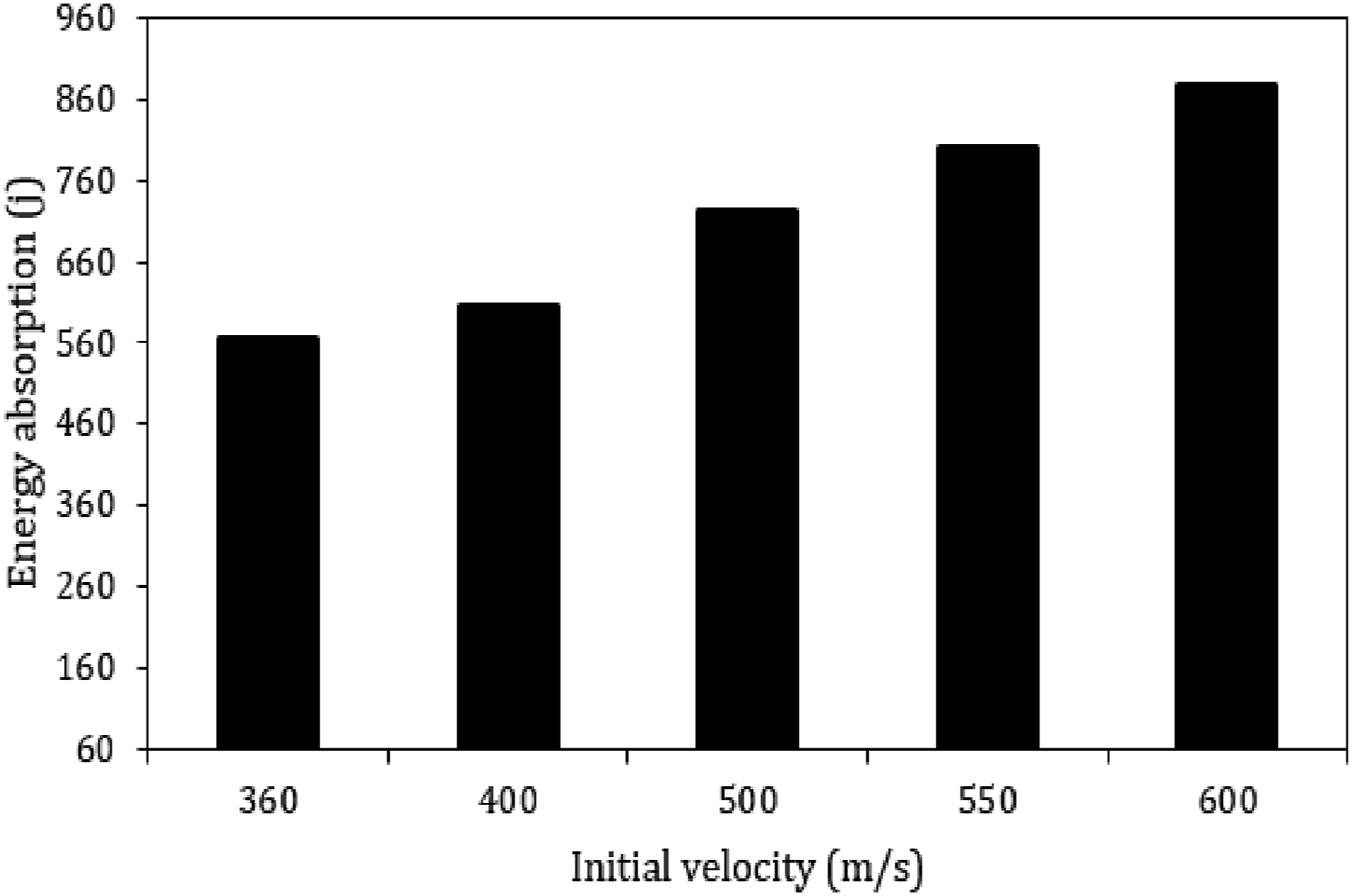
At higher velocities, the plot exhibits a linear relationship, characterized by a slope approximately equal to 1. This asymptotic behavior can be attributed to the energy balance equation. This trend can be elucidated by the amplified input velocity, which necessitates a shift in the required failure mechanisms for penetration, and heightened influences of strain rate effects. Notably, the analytical solution breakdown energy absorption into specific mechanisms and demonstrates a congruent trend in all cases. The proposed analytical model provides an efficient method ro estimate the BLV and energy absorption mechanisms without requiring extensive computational resources or complex setups. This is especially useful in the early design stages, when evaluating multiple configurations and in case where experimental setups introduce uncertainties.
Numerical simulation results
Model validation
In this section, we compare the results obtained from the numerical model to a subset of experimental tests. In high-velocity impact experiments, the only measured quantities are the input and residual velocities of the projectile. Consequently, there are no variables that directly depict the condition of the target during the projectile perforation process. Therefore, the validated finite element (FE) model is employed to examine the response of sandwich panels featuring FML skins and AAC cores.
Obtained results from FEM versus some experimental impact tests.
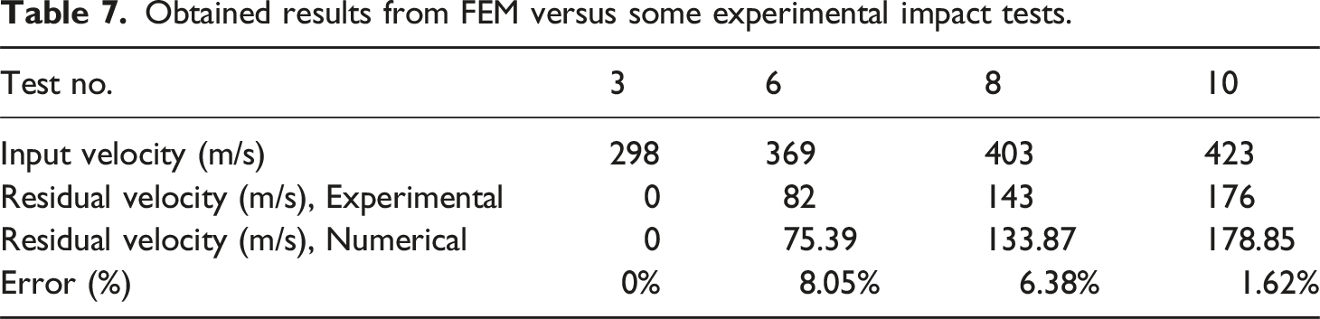
Figure 18 offers an insightful portrayal of the damage progression incurred by FMLRAAC when impacted by a flat nose-shaped projectile with an initial velocity of 403 m/s. This illustration elucidates the specific characteristics of the full perforation of different component of the target: the front face sheet, the AAC core, and the back face sheet. The penetration process can be divided into six distinct phases of energy absorption, each linked to a different component of the target. Due to the considerably higher stiffness of the FML skins in comparison to the AAC core, a significant portion of the projectile’s kinetic energy is primarily dissipated during the perforation of both face sheets. The simulated damage evolution of the FMLRAAC impacted with flat nose shape projectile: (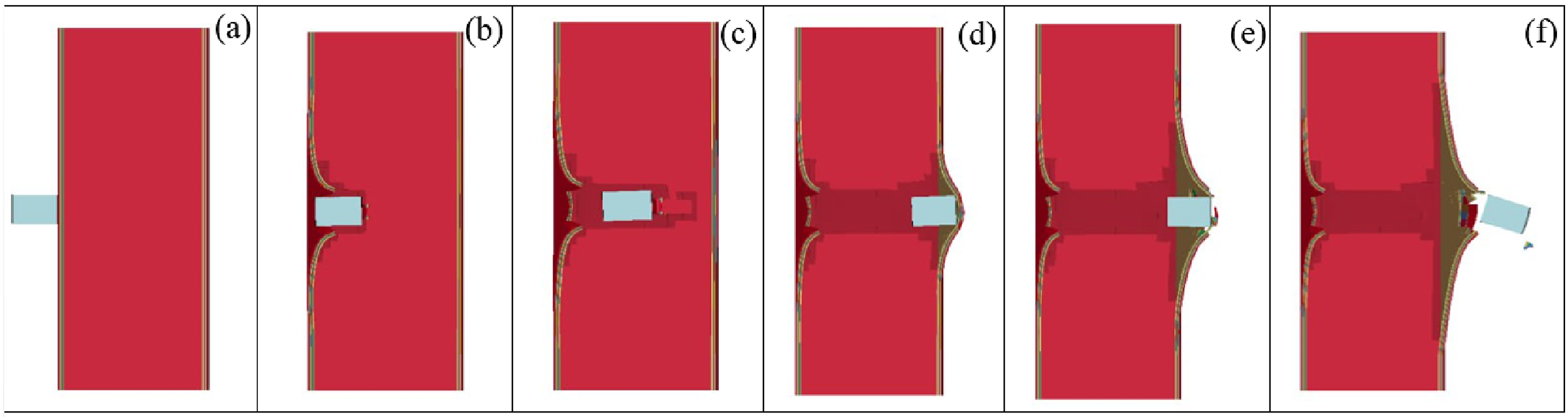
Figure 19 depicts the computed energies obtained through LS-DYNA at V
i
= 403 m/s with a flat nose-shaped projectile. In this analysis, the total energy of the numerical model at any given moment encompasses several components, including the kinetic energy of the projectile (KE
projectile
), the structural kinetic energy (KE
structure
), the total internal energy across various components of the entire structure (IE
structure
), the sliding energy (SE) associated with friction, the hourglass energy (HGE), and similar energies attributed to eroded elements. Specifically, the sliding energy is determined for each pair of parts in contact by integrating the friction force along the displacement. The hourglass energy characterized by zero energy represents a non-physical mode of deformation, resulting in zero strain and stress. It is imperative for this non-physical energy to be minimized.
36
Consequently, the energy balance calculations and predictive capabilities of the FE models can be deemed reliable and credible. Time history of different energy transformation during perforation for flat nose shape projectile.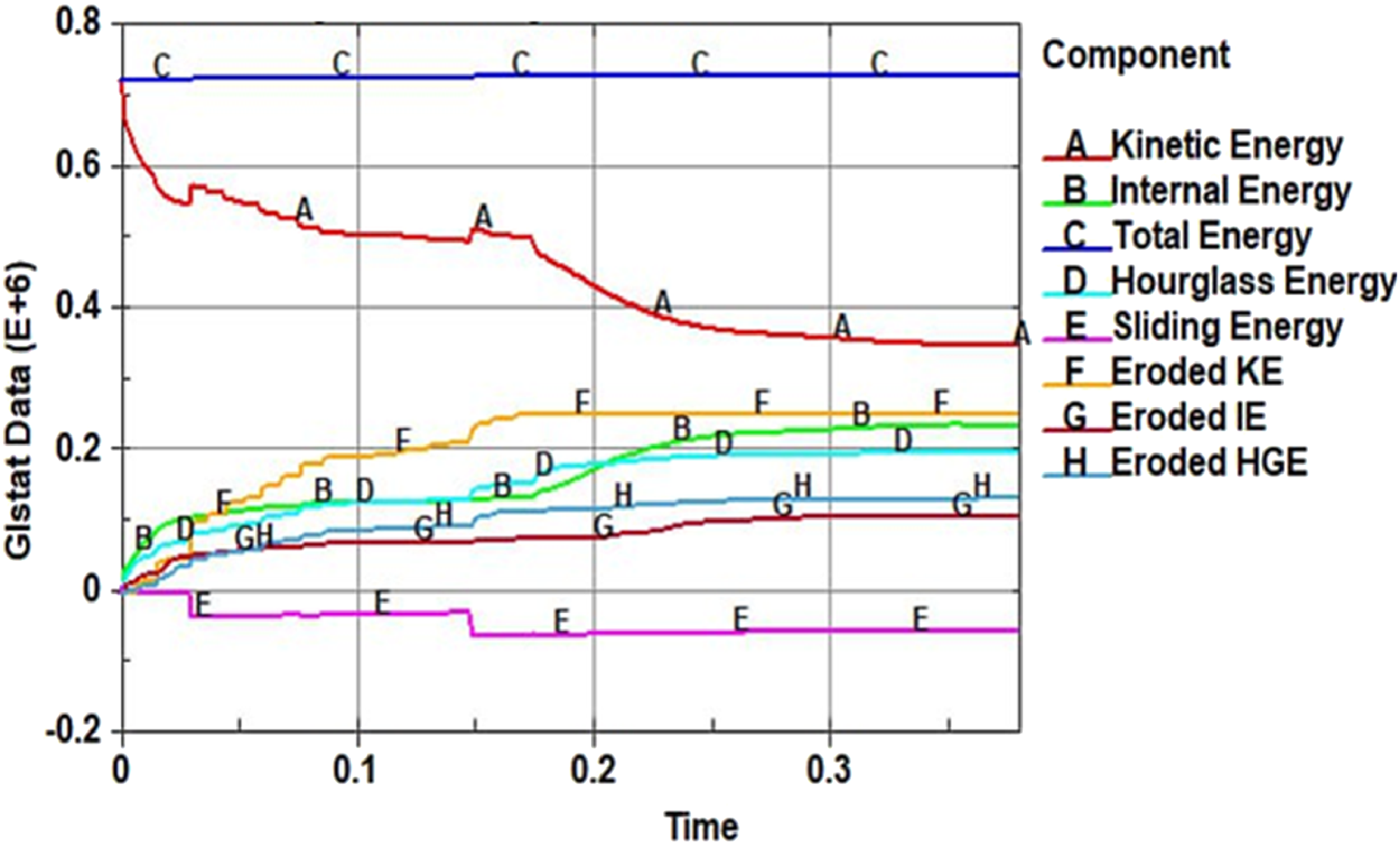
The validated numerical results have proven to be accurate, enabling their application in a more in-depth examination of the impact of various projectile nose shapes on BLV of FMLRAAC composite sandwich panel. Additionally, these validated predictions, when compared to experimental data, were used to explore parameters such as the overall absorbed energy related to the plastic deformation of FMLRAAC panels, the kinetic energy of the projectile, and specific energy absorption. Subsequently, through numerical simulations, the damage progression, resulting failure modes, and trajectory deviation of each projectile were predicted and discussed in detail.
Figure 20 displays a history plot of the residual velocity for various simulated nose shape projectiles, all with an input velocity of 403 m/s. The penetration ability of the projectiles, from the smallest to the largest, follows this order: flat, truncated 90, hemispherical, truncated 60, conical 90, ogive, and conical 60. As the nose angle of the projectile increases, the residual velocity of the projectile decreases. Residual velocity (m/s) legend of various nose shape projectiles.
Deformation and failure modes
A series of simulations were carried out with different projectile nose shapes, all with an initial impact velocity of 403 m/s to clarify the generated deformations. Figure 21 presents a plot of the transverse displacement of the outer FML layer of the bottom face sheet for various nose shape projectiles. As discussed earlier, the damage pattern on the back surface is influenced by shock wave reflection, composite laminate bending, or both, resulting in a tensile stress state on the back surface. The simulations revealed phenomena like back-face bulging and bending. Additionally, as the sharpness of the projectile nose shape increases, penetration becomes more localized, and the plugging phenomenon disappears, leading to a reduction in transverse deflection at the edge. The transverse displacement history curves of the rear FML face sheet for various nose shape projectiles. (V = 403 m/s).
Figure 22 displays a plot of vertical displacement versus lateral displacement of the outer FML layer for various nose shape projectiles. It can be observed that for sharper nose projectiles, the maximum ratio of vertical to lateral displacement decreases, and the damaged area becomes more localized. Sharper projectiles perforate panels faster, and the plastic stress waves do not have enough time to propagate throughout the entire back face sheet of FMLRAAC. Projectile’s trajectory of various nose shape projectiles while passing through the thickness of target. (V = 403 m/s).
Figure 23 presents a cross-sectional view of the rear FMLRAAC surface at an impact velocity of 403 m/s for various nose shape projectiles. The induced shear stress on the projectile is inherently dependent on the level of failure interaction between the projectile’s geometry and the overall local/global FML deformation. The FML failure pattern resembles a cone shape, with larger fiber damage occurring around the peripheral region of the maximum contact area of the projectile. Features of bottom FML surface of FMLRACC perforating by various nose shape projectiles. (V = 403 m/s).
It is clear that the damage area of both fiber and metal failure modes becomes smaller when the contact area of the projectile nose with the FML face sheet is reduced. Additionally, smaller bending deformation and tensile stress fields cause less damage to the FML layer that is closer to the back side rather than the front side of the FML layer. When comparing the damage location on the rear FML layer impacted by different projectiles, it is observed that sharpening the projectile’s nose leads to severe localized deformation under its contact area. This phenomenon is a significant advantage of using FML as an insulation component for protective structures because, on one hand, it limits the damage to a distinct zone while maintaining the structural integrity. On the other hand, the presence of a ductile metal layer can act like a barrier, limiting core failure and preventing the expulsion of broken and separated fragments, thus protecting the structure located behind the FML target from multiple small impacts.
Energy absorption
To elucidate the underlying penetration mechanism, the effect of projectile nose shape on the EA and SEA of the FMLRAAC was further analyzed. Figure 24 illustrates the trend of energy transformation during the complete perforation of the FMLRAAC target subjected to various nose shape projectiles by simulation. Over 8% of the absorbed energy by the FMLRAAC is dissipated through the kinetic energy of the impacted projectile. This analysis helps to understand how different nose shapes affect the energy absorption and dissipation during the penetration process. Energy absorption versus time diagram of various nose shape projectiles while the (a) Kinetic energy of the impacted projectiles, transferred to (b) Internal energy of FMLRAAC panel during penetration process. (V = 403 m/s), and (c) Energy contribution of different FMLRAAC components; (c-1) AL and (c-2) E/glass composite layers and the (c-3) AAC core.
Overal this energy is transferred to the internal energy of the target, involving the top and rear face sheets and the core. Additionally, the sliding of the projectile due to friction and the geometry of the projectile’s nose causes deviation and results in the dissipation of some energy, as discussed previously. Energy dissipation in the form of heat, vibration, and interlaminar/interface damage is minor, and their proportion is negligibly small compared to the overall absorbed energy. 37
From diagram (a), it is apparent that the flat nose projectile experiences the maximum drop in kinetic energy during the 0.3-0.5 ms of travel through the thickness of the specimen, compared to other shapes. Consequently, diagram (b) shows the internal energy of the whole structure, depicting the trend of energy absorption, where the flat nose projectile has the highest value, approximately 30% higher than others. This analysis highlights how the different projectile nose shapes influence energy absorption and dissipation during the penetration process, with the flat nose shape exhibiting distinct characteristics.
The idealized trend of the internal energy diagram has three stages, corresponding to the perforation of the top face sheet, the tunneling process through the core, and finally, the perforation of the bottom face sheet. Moreover, the results demonstrated that the penetration time in the core and rear face sheet is higher than the penetration time of the front face sheet. Each of these stages is accomplished with different damage occurrences. Figure 24 (c-1, c-2, and c-3) clarifies the energy-time trend of each component, providing insights into the specific energy absorption patterns during the perforation process. The first part of the diagram is related to the top composite sheet fiber fracture, followed by a plateau region, and then rear composite sheet fiber fracture and delamination. It’s worth noting that in the meantime, the deformation of the AAC core during penetration is mainly manifested as local cell wall buckling deformation near the rear FML face sheets (c-3). As the projectile nose shape becomes sharper, the deformation area, also known as dishing, of the back FML face sheet decreases noticeably, and the degree of densification of the AAC core is also reduced. Consequently, the degree of tensile stress is directly related to the nose shape of the projectile. In other words, by increasing the sharpness of the projectile nose shape, the contact area with the bottom FML surface becomes smaller, and the perforation process is followed by localized indentation.
The failure morphology of the impacted FMLRAAC with different nose shape projectiles is demonstrated in Figure 25. The maximum principal stress and strain, as well as deformation of the back FML surface, are extracted from the simulations. It is obvious to see that for all projectiles, the structural damage of the FMLRAAC is mainly concentrated in the contact collision area between the impactor and the FML skin. During the impact process, the E glass/epoxy composite layerundergo matrix cracking, fiber breakage occurred along with delamination, and consequently, the Al skin underwent plastic deformations until this layer fractured permanently at the impact position in the back FML face sheet, leading to petalling outwardly. Somehow, for truncated and flat nose projectiles piercing took place (see Figure 23). Overview of numerical outputs of principal true stress, strain, and deformation of rear face of FMLRAAC panel impacted by various nose shape projectiles.
The SEA, corresponding to the deformation features of the FMLRAAC target for all projectile nose shapes when the projectile input velocity was about 403 m/s, is shown in Figure 26. The SEA ability of the target directly reflected the ballistic resistance of the projectile.
37
The SEA parameter decreased with the increase of the nose angle of the projectile. However, the further increase of nose angle had little improvement on the SEA. The comparative chart of EA and SEA of the FMLRAAC panel impacted by various nose shape projectiles.
Comparing the presented stress-strain diagrams, it is concluded that the flat nose projectile produced the maximum strain zone because the projectile cut the laminate through shearing action. On the other hand, ogive nose and conical60 nose led to the minimum strain area because the projectile perforated the laminate with minimal delamination and tearing of the AL skin. Due to the decrease in contact area between the projectile nose and the FMLRAAC, the EA and SEA values decreased slightly. However, the lower nose length made a larger contact area than others, causing higher ballistic resistance and energy absorption capability values. Moreover, the EA remained likely steady as the projectile penetrated the target. Afterwards, the failure mechanisms of the FMLRAAC target transformed from shear deformation to tensile deformation, resulting in a small decrease in ballistic resistance.
It can be concluded that the ogive nose projectile presented the lowest EA while this amount is the highest for the flat nose projectile. The ogive projectile is the most efficient perforating geometry when compared with other nose shapes. Moreover, a relevant observation can be drawn from this numerical analysis: the prediction of absorbed energy of the FMLRAAC strongly depends not only on the projectile geometry but also on the target reinforcing components. For all values of geometry ratio, sharper projectile shapes resulted in a lower ballistic limit than that presented by the flat projectiles, as it has been observed in numerous works.38,39
Conclusions
The present study deals with the impact behavior and induced failure mechanisms of a FML reinforced AAC core composite sandwich panel through a combination of experimental, theoretical, and numerical approaches. The creation of composite sandwich panels and experiments lead to a realistic and optimal representation of the sandwich configuration, thereby enabling accurate predictions of the effective impact phenomena through analytical solutions and numerical approaches. Experimental trials were explicitly designed to ascertain the ballistic limit velocity (BLV) of FML reinforced AAC subjecting to impact loading of a rigid flat-nosed projectile. A reasonable correlation between the analytical and numerical models and the experimentally tested composite sandwich panel was achieved, with an error of less than 10%. As a result, the majority of the energy dissipation during impact loading was absorbed through the failure of FML face sheets due to their high stiffness and strength.
The results of the study highlight the extreme anisotropic stiffness properties of the FMLRAAC composite sandwich panels, which can be advantageous in protective applications where resistance to unexpected environmental hazards and impact is crucial. The lightweight nature of these panels also makes them attractive for use in hazardous zones that are prone to impacts and explosions. Additionally, the presence of an outer ductile metal layer in FML offers a significant advantage in ballistic protection, as it acts as a barrier to contain and prevent the expulsion of fragmented core material. This protective feature helps safeguard structures located behind FMLRAAC targets from multiple small impacts. Overall, these findings emphasize the potential utility of such composite sandwich panels in various protective and impact-resistant applications.
Footnotes
Declaration of conflicting interests
The author(s) declared no potential conflicts of interest with respect to the research, authorship, and/or publication of this article.
Funding
The author(s) received no financial support for the research, authorship, and/or publication of this article.