
Abstract
The carbon fiber reinforced polyetheretherketone (CF/PEEK) composite material can achieve high efficiency and integrated assembly molding through in-situ consolidation, suitable for the preparation of high-speed motor rotor sleeves. However, the high forming temperature of CF/PEEK may cause demagnetization of the magnet once the temperature exceeds the curie temperature of the magnet. To address the insulation issues during the sleeve forming process, this study proposes using metal-containing multilayer thermal insulations (MTI) to prepare the insulation layer, which takes advantage of the heat transfer within the metal layer to achieve thickness-wise insulation. A finite element heat field model is established to analyze the effect of material thermal properties, layer structure, and thermal field conditions on the thermal insulation effect. The response surface methodology analysis shows that metal materials with high thermal conductivity and high volume-specific heat have better insulation performance. The highest temperature of the bottom surface of the copper-containing MTI is only 64% of that of the glass fiber reinforced polypropylene (GF/PP) layer MTI. Analysis of the layer structure shows that the closer the metal layer is to the heat source, the better the insulation effect. The sensitivity analysis of the thermal field conditions shows that the thermal conductivity of the inner layer has a greater impact on the insulation effect. Subsequently, the MTI containing copper was optimized in response to the specific insulation requirements of the motor rotor sleeve, providing a reference for the application of in-situ consolidated integrated assembly molding in thermoplastic composites.
Introduction
High-performance thermoplastic composites have been one of the hotspots in composite materials research and application in recent years. They have excellent toughness, weather resistance, and high-temperature resistance. Moreover, thermoplastic composites only undergo physical changes during the forming process, and they can be consolidated in situ forming, which is a key factor in reducing the manufacturing cycle and application costs of composite materials. 1 High-speed permanent magnet motors have technical advantages such as simple structure and high power density, which are an effective way to solve energy problems and have broad application potential. 2 However, the permanent magnets on the rotor of the motor have low tensile strength and require protection with a sleeve. The use of in-situ solidification molding technology of thermoplastic composites to prepare rotor sleeves can achieve integrated molding of the sleeve and the rotor permanent magnet surface, simplifying the manufacturing process, reducing manufacturing costs, and improving manufacturing efficiency. 3
However, the molding temperature of high-performance thermoplastic composite materials is much higher than the temperature resistance of the permanent magnet in the motor rotor, so a thermal insulation layer needs to be set between the permanent magnet and the thermoplastic composite material sleeve to isolate the high temperature during the molding process and bear the pressure during the molding process. Taking CF/PEEK material, the most commonly used high-performance thermoplastic composite material for in-situ molding, as an example,
1
its commonly used molding temperature is 380°C–400°C,
4
which is much higher than the allowable temperature of the permanent magnet, such as 80 °C–220°C
5
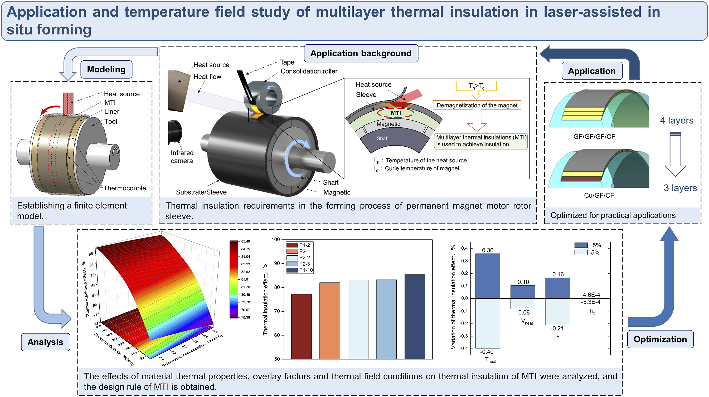
for rubidium iron-boron (NdFeB) material. To prevent the high temperature during the sleeve molding process from causing demagnetization of the permanent magnet, a thermal insulation layer needs to be set between the permanent magnet and the sleeve, as shown in Figure 1. Moreover, the magnetic field strength of the permanent magnet will significantly decrease with the increasing distance, so the thickness of the thermal insulation layer material should be as thin as possible to reduce the impact on the magnetic field strength. The in-situ consolidation pressure of CF/PEEK can reach over 30 MPa. Common high-temperature insulation materials, such as fiber materials and porous materials, are difficult to maintain good insulation performance under such high pressure. Multilayer thermal insulations (MTI) have excellent insulation performance and can achieve functions that single insulation materials cannot, and are often used to prevent high-temperature shock and long-term thermal load.
6
They have been used in high-temperature thermal insulation requirements of re-entry vehicles
7
and fuel cells
8
thermal insulation. In this article, MTI is used to achieve insulation during laser-assisted in-situ consolidation. Application of MTI in the motor rotor.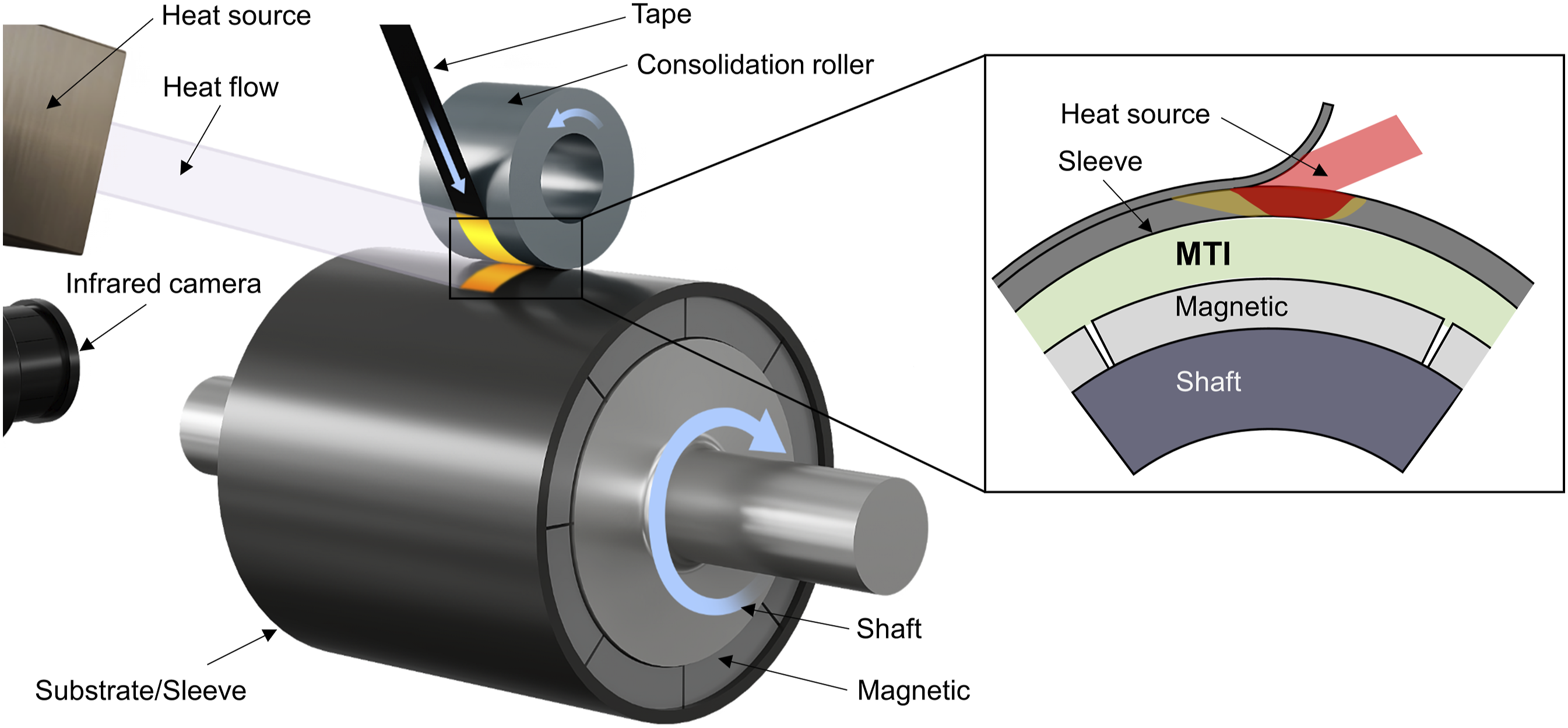
MTI has strong designability and can be designed to meet the thermal insulation needs of specific occasions by designing different materials and combinations. To obtain protective materials with high thermal insulation, it is possible to enhance thermal insulation performance, and reduce weight and thickness through continuous research, using structural design and material combinations 9 The thermal insulation performance of MTI depends on many factors. Existing research has analyzed the influence of factors such as material,7,10–18 layer thickness,14,15,18–21 number of layers,7,10,12–15,19,20,22,23 and layer structure7,11,12,15,17,19–21 on insulation performance, and comprehensively considered the use conditions to optimize the design of thermal insulation materials with excellent performance. However, in current high-temperature insulation research on MTI, the metal layer mainly plays a role in shielding thermal radiation, and the research and application of in-plane heat conduction behavior of high thermal conductivity metal materials are few.
Some researchers have discovered that it is possible to achieve external insulation by designing the thermal conductivity orientation of materials and utilizing high thermal conductivity in-plane. Some studies have also suggested that this method can meet the specific insulation needs of certain occasions. Zhao et al. 24 investigated the anisotropic thermal conductivity of polypropylene/carbon nanotube multilayer stacking and found that the multilayer structure provided excellent directional heat dissipation for thermal insulation. Zhou et al. 25 adjusted the graphite content in graphite flakes/Si/Al composites to increase the in-plane thermal conductivity and found a decrease in the out-of-plane thermal conductivity. Chen et al. 26 adjusted the graphite content in Al/graphite composites to increase the in-plane thermal conductivity and found a decrease in the out-of-plane thermal conductivity, to meet the thermal management needs in electronic packaging and other fields. While increasing the proportion of high thermal conductivity graphite in-plane can reduce the out-of-plane thermal conductivity, the impact of flake graphite, as a non-continuous phase, on the overall thermal performance of the material is limited. Ren et al. 27 studied the effect of a layup sequence of materials with different thermal conductivity on the overall thermal conductivity of the material and found that the thermal conductivity of the composite material could be greatly improved by establishing a continuous thermal conductivity path, and with the increase of the thermal conductivity of the material in the plane. Additionally, they observed that as the in-plane thermal conductivity of the material increases, the out-of-plane thermal conductivity decreases. Huang et al. 28 investigated the effect of the proportion of in-plane high thermal conductivity materials on the overall thermal conductivity of composite materials. They found that due to the strong anisotropy of thermal conductivity of the composite material, as the proportion of in-plane high thermal conductivity materials increases, the out-of-plane thermal conductivity of the composite material decreases significantly. Furthermore, they predicted that this high in-plane thermal conductivity material could serve as a thermal barrier by dissipating heat in-plane, making it potentially applicable for insulation needs. Some researchers have analyzed the thermal insulation of local heat sources by in-plane thermal conductivity. Ren et al. 29 studied that under local heating conditions, the multilayer heterogeneous structure is conducive to in-plane heat transfer, which is suitable for overheating protection materials such as spacecraft shells. Xin et al. 30 found that the high thermal conductivity of thin sheet material has a good control effect on the centralized local heat source, which can weaken heat concentration. Liu et al. 31 prepared alternating stacking epoxy composites (AECs) by filling epoxy resin with hexagonal boron nitride (h-BN) and expanded vermiculite (E-ver) as heat dissipation and insulation layers, respectively. This anisotropic structural design provides vertical heat insulation and local hot spot protection and exhibits good heat dissipation performance compared to homogeneous materials. From existing studies, it can be seen that the method of designing material heat conduction orientation has the potential to achieve insulation, but lacks analysis and research on specific practical applications.
This paper addresses the insulation problem in the process of in-situ consolidation of thermoplastic composites for the preparation of motor rotor sleeves. A method is proposed to use metal-containing MTI and achieve external insulation of the insulation layer structure through in-plane heat conduction of the metal material. This provides a convenient and efficient way to achieve insulation protection of local instantaneous heat sources in laser-assisted in-situ consolidation molding. The study mainly investigated the thermal field characteristics and the thermal insulation effect of MTI when subjected to a moving heat source. Firstly, considering the heating characteristics of the heat source in laser-assisted in-situ consolidation and the significant in-plane heat transfer phenomenon of metal-containing MTI, a three-dimensional finite element thermal field model of MTI under moving heat source heating was established. Layer-to-layer thermal resistance measurement experiments and finite element model validation experiments were then performed. Subsequently, based on the finite element thermal field model, the influence of material thermal properties, layer structure, and thermal field conditions on the thermal insulation effect was analyzed, and relevant influence rules were obtained. Finally, based on the obtained rules, the material and thickness of MTI were optimized for a specific application case of an insulation layer, achieving a thinner insulation layer.
Materials and experiments
Materials
In this paper, MTI is used to meet the heat insulation requirements for CF/PEEK laser-assisted in-situ consolidation integrated assembly to manufacture motor rotor sleeves. The MTI studied is mainly composed of three material layers. The outermost layer is CF/PEEK structural material, which is used to realize the integrated manufacturing of MTI, and the outer layer is CF/PEEK structural layer in-situ consolidation molding. The middle layer adopts GF/PP composite material with low forming temperature to prevent the influence of MTI on the rotor permanent magnet during the preparation process and mainly realizes the low-temperature bonding between the layers. The inner layer is a metal material layer, which uses the high thermal conductivity of the metal material to form in-plane heat dissipation to the instantaneous local heat source and realizes the out-of-plane heat insulation along the thickness direction of MTI.
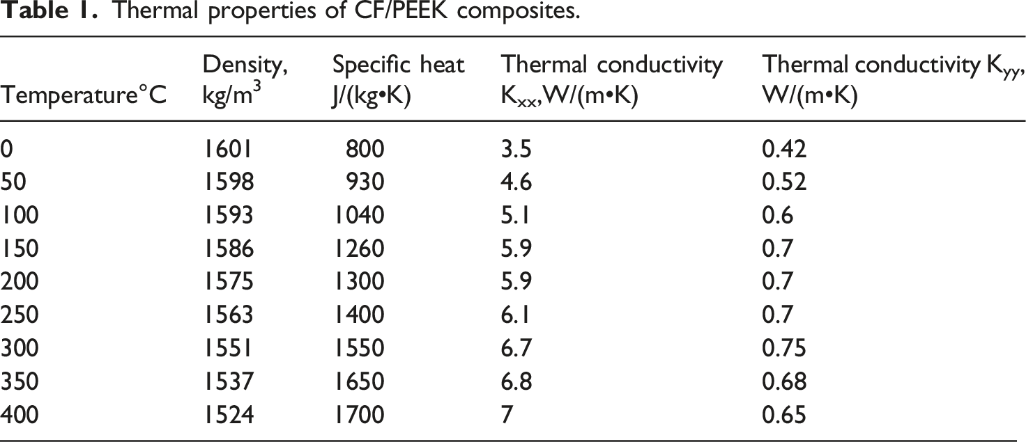
Thermal properties of CF/PEEK composites.
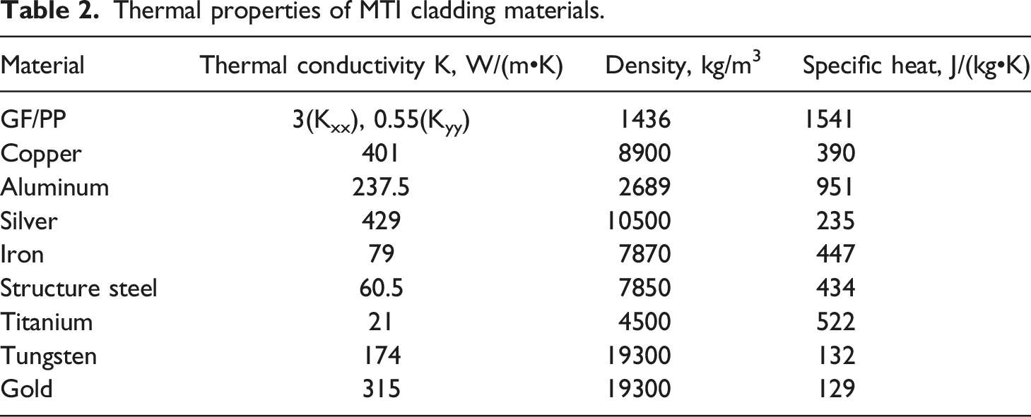
Thermal properties of MTI cladding materials.
Multilayer thermal insulations molding equipment and preparation
The forming equipment uses a three-axis winding machine designed by Nanjing University of Aeronautics and Astronautics, which is mainly composed of a winding machine tool, heating module, pressure module, feeding module, etc. The maximum spindle speed of the winding machine is 30r/min. The machine tool can realize spiral winding. The heating module can be replaced by different heating elements to achieve different heating methods, commonly used heating methods include laser, infrared, and hot air. The cylinder is used to push the press roll to generate forming pressure. The diameter of the press roll is 100 mm. The press roll material is made of stainless steel. Thermoplastic tape with a width of 6.35 mm is commonly utilized for wrapping applications. The forming equipment is shown in Figure 2. MTI forming equipment.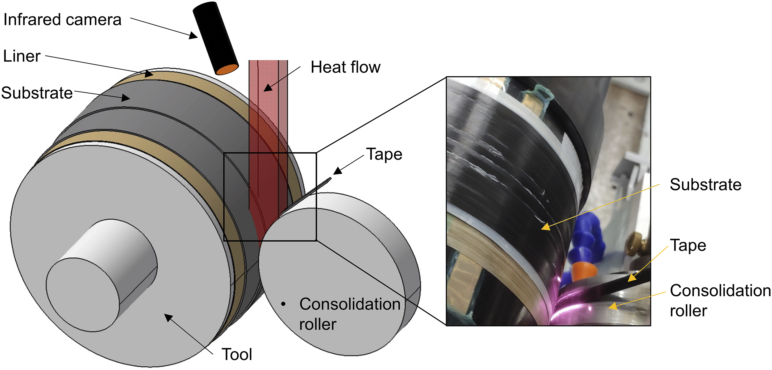
In this paper, MTI is mainly composed of three kinds of material layup. GF/PP material with a low melting point is used as the intermediate bonding layer, and GF/PP strip is heated and wound by Deli 2000 W high-power hot air heating equipment. The fused PP resin is used to form the bonding between metal material and CF/PEEK material, to realize the preparation of the MTI sample.
Multilayer thermal insulations heat insulation experiment
To investigate the influence of material thermal properties, layer structure, and thermal field conditions on the thermal insulation effect of MTI, this paper simplified the laser-assisted in-situ consolidation forming conditions. The laser was used to irradiate the surface of MTI in one circle to analyze the thermal field characteristics and the thermal insulation effect of MTI. The model of the laser is LDM 2000-60, with a maximum power of 2000 W. It can automatically control the temperature through its integrated module, and the temperature control range is 195° C to 1260° C. The laser irradiation position was adjusted to ensure that the beam was at the center of the MTI axis and fully irradiated on the surface of the MTI. The spindle was rotated to make the laser irradiate MTI at a constant speed for one circle, and the temperature history of the bottom layer of MTI was measured to calculate the thermal insulation effect. The experimental and temperature measurement point schematic is shown in Figure 3. Temperature measurement methods: (a) Schematic diagram of a temperature measurement experiment, (b) schematic diagram of temperature measurement points, (c) physical diagram of temperature measurement.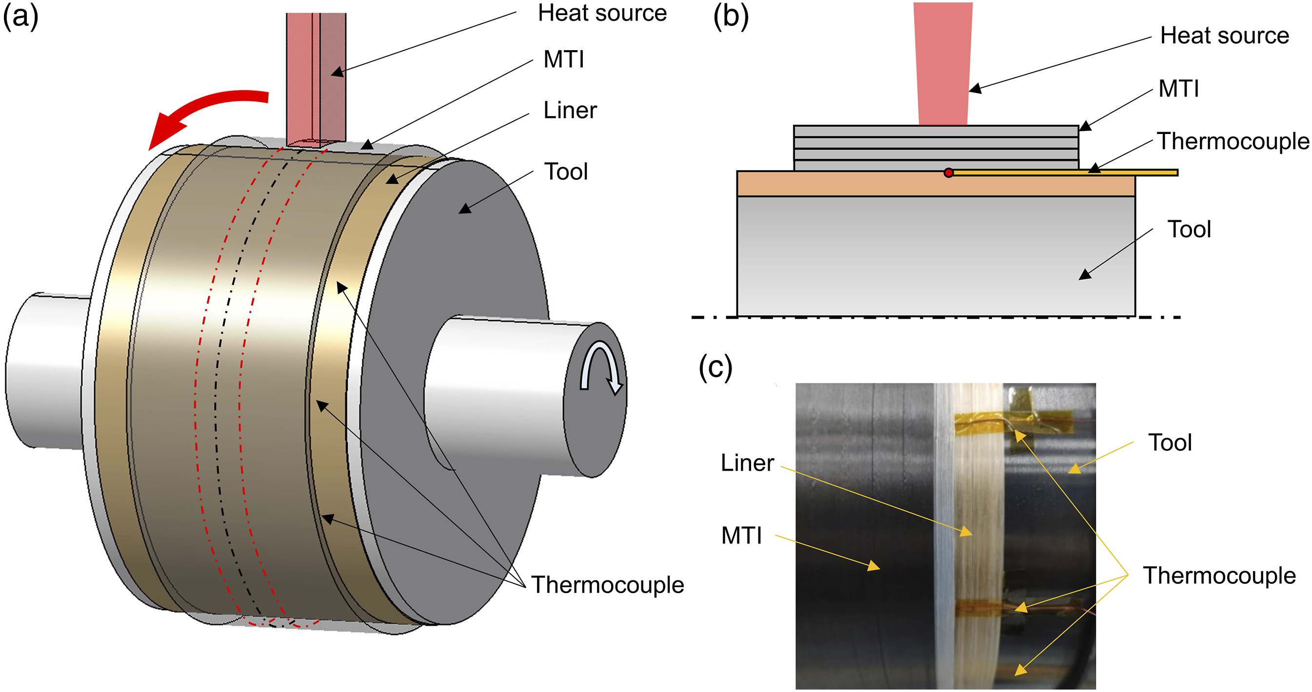
In this paper, an infrared camera is used to observe the temperature of the moving heat source on the surface of MTI. Meanwhile, a multi-channel wireless temperature measurement unit with thermocouples was applied to measure the internal temperature of MTI. The model of the infrared camera used is FOTRIC-626, with a temperature measurement range from −20°C to 650°C, infrared resolution of 384*288, temperature measurement accuracy of plus or minus 2°C, and a frequency of 30 Hz. The model of the multi-channel wireless temperature measuring unit is DAQM-4203, which can realize the temperature measurement of 10 Hz in a single channel. In this study, multiple fine thermocouples with a diameter of 0.5 mm were installed in the sample to detect the temperature history during the heating of the moving heat source. To reduce the influence of the embedded thermocouple on the thermal field of the sample, an extremely fine thermocouple with a measuring point diameter of 0.5 mm was used and the thermocouples were placed at intervals.
Due to the high thermal conductivity of the metal mold, it has a significant influence on temperature measurement. To ensure the accurate temperature measurement of the experimental temperature, it is usually necessary to do heat insulation between the temperature measurement point and the metal mold. 34 In this paper, to avoid the influence of metal mold on experimental temperature measurement, GF/PEEK composite material with low thermal conductivity is wrapped on the surface of the metal mandrel as the lining layer to insulate the metal mold. Temperature measurement points were set on the outer surface of the lining layer to measure the internal surface temperature of the multilayer thermal insulation material.
Evaluation of thermal insulation effect
The thermal insulation effect of MTI is evaluated by the thermal insulation effect, and the thermal insulation effect D
i
is defined as follows: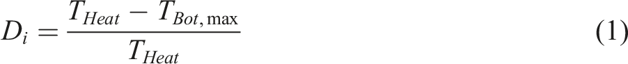
Experimental testing of multilayer thermal insulations heat insulation
To verify the accuracy of the finite element simulation results of the thermal field, two types of layered insulation materials were prepared in this paper. The layered structures of the two MTI were GF/GF/GF/GF/CF and Cu/GF/Cu/GF/CF, respectively, with a total thickness of 0.75 mm, as shown in Figure 4(a) and (b). Thermocouples were placed at the axis at the bottom of the layer to collect temperature history and compare with the results of finite element calculation to validate the accuracy of the model. Temperature measurement experiment samples: (a) GF/GF/GF/GF/GF/CF layer, (b) GF/Cu/Gf/Cu/CF layer.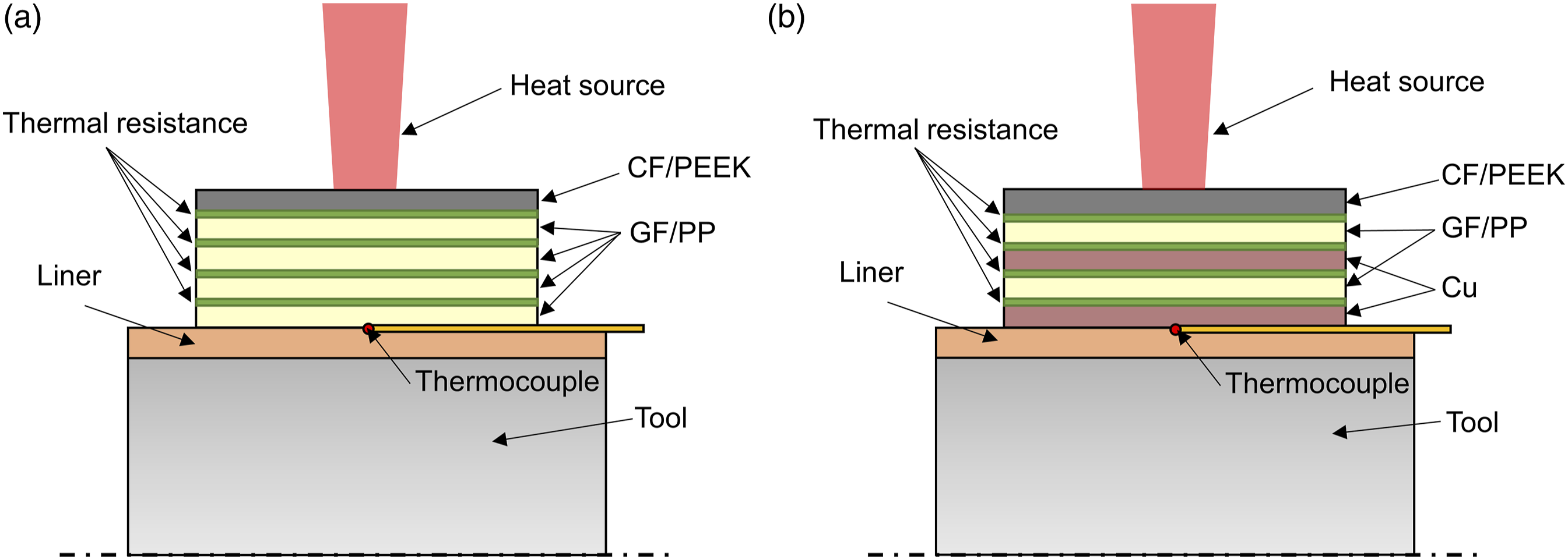
Finite element thermal field analysis
Three-dimensional transient thermal field model
This paper mainly analyzes the thermal field characteristics and thermal insulation effect of metal-containing MTI. According to the material properties, the thermal diffusion coefficient of metal materials is much higher than that of composite materials, especially the thermal diffusion coefficient of high-conductivity metal materials is many orders of magnitude higher than that of common CF/PEEK and GF/PP materials. Therefore, it is necessary to analyze the thermal field characteristics of MTI and establish a suitable thermal field model. The thermal diffusion coefficient α is as follows:
Calculation of the time scale of thermal diffusion of materials in the direction of heat source τ
c
:
Taking the length dimension as 1 mm, the time for copper thermal diffusion to cover 1 mm is 0.0091 s, and the time for the heat source to move 1 mm is 0.02 s. As can be seen, under the heat source movement rate studied in this paper, the thermal diffusion time scale of high thermal conductivity metal materials is shorter than the heat source movement time, and the thermal diffusion rate is faster than the heat source movement rate. This indicates that the in-plane heat conduction of metal materials cannot be ignored, and a three-dimensional thermal field model needs to be established.
According to Fourier's law of heat transfer, the partial differential equation of a three-dimensional thermal field is:
This study uses ANSYS Workbench finite element software to establish a three-dimensional finite element thermal field model. The MTI model is cylindrical in geometry, with an axial length of 64 mm, an inner diameter of 150 mm, and a thickness of 0.75 mm, and is divided into five material layers, each with a thickness of 0.15 mm. A transient thermal field solution model is adopted, and the APDL program is used to achieve the movement of the uniform temperature heat source and solve the instantaneous thermal field of MTI under the heating of the moving heat source. To simplify the calculation and ensure the accuracy of the finite element model, the following assumptions are made in this paper: 1. The model does not take into account the heat generated by the crystallization and melting of the matrix material in the composite. The heat generated by the crystallization and melting of the matrix material in the composite relative to external input can be ignored,
35
so the model does not consider its influence. 2. The thermal conductivity of each layer in MTI is the same. Since GF/PP material with a low melting point is used as the bonding layer of the thermal insulation layer in this paper, the interlayer bonding of MTI is formed by the melting of the GF/PP material substrate, so it is assumed that the interlayer thermal conductivity of each layer is the same.
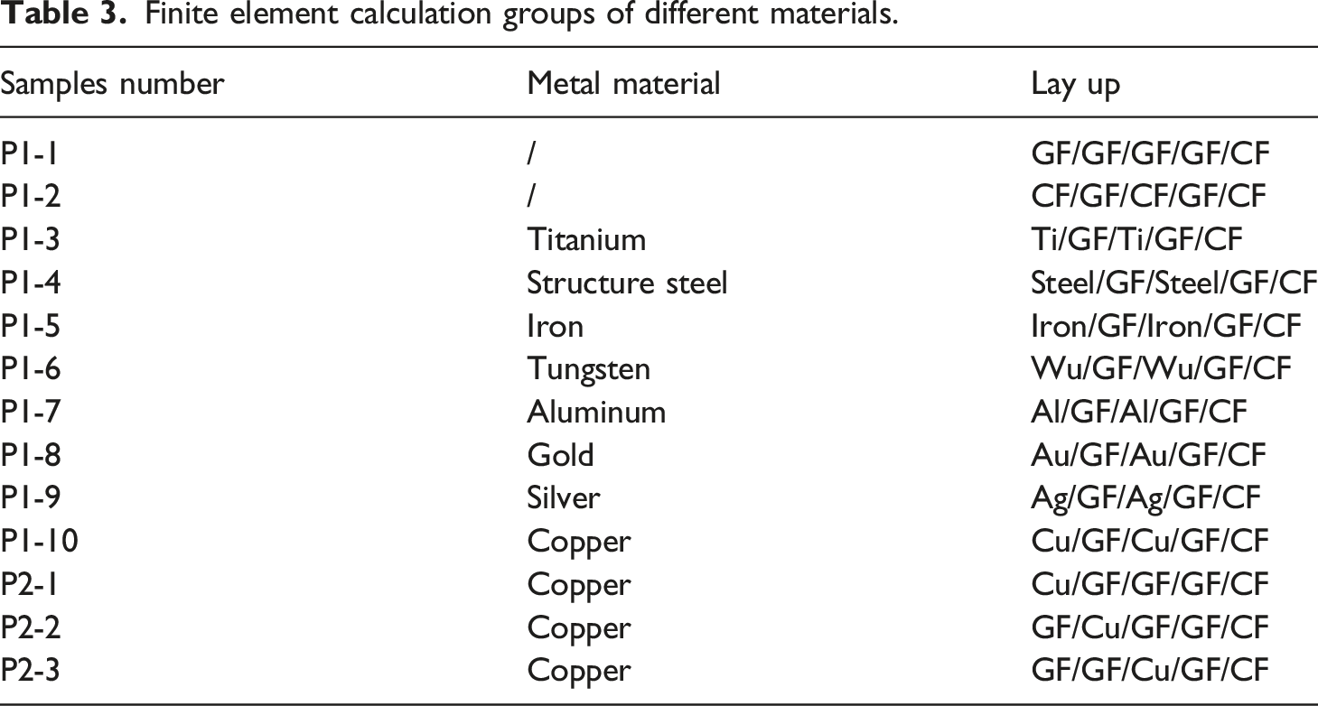
Finite element calculation groups of different materials.
Heat source conditions
In the experiment, the actual size of the laser heat source used was 8 mm wide and 20 mm long. The rectangular heat source was irradiated on the outer surface of MTI, and the line speed of the moving heat source was about 40 mm/s. During the moving heat source heating experiment, an infrared camera was used to observe the temperature distribution of the heat source, and the observation results of the infrared camera were shown in Figure 5. Temperature observation of heat source: (a) Infrared image of heat source heating region, (b) three-dimensional temperature distribution of heat source.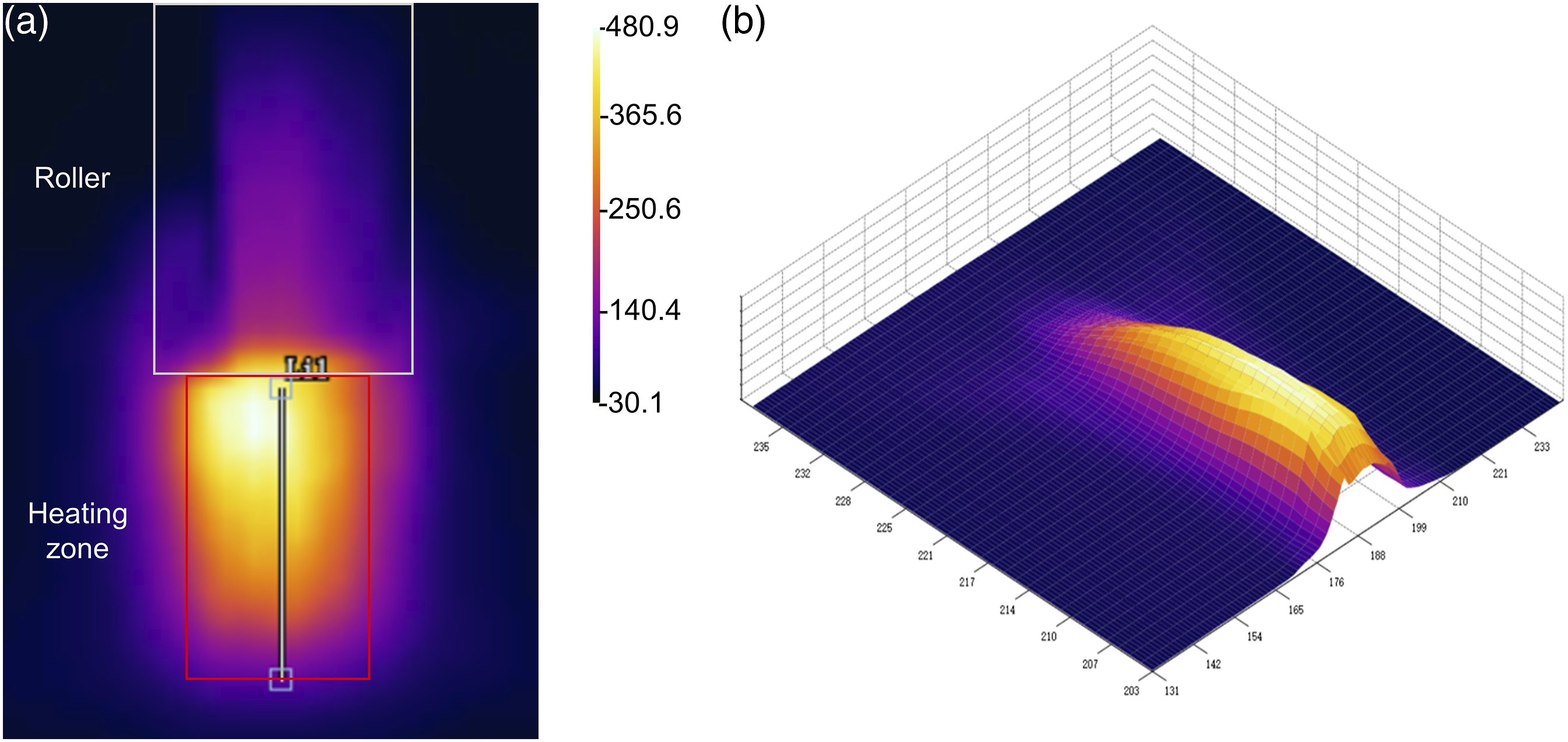
The main focus of this paper is to study the thermal insulation performance of MTI. The heat source condition was simplified to a rectangular uniform temperature load to simulate the molding temperature field more directly and accurately, thus avoiding errors caused by material non-uniformity. The actual temperature distribution was measured using an infrared camera. To ensure that the thermal history was the same, the temperature distribution obtained by the infrared camera was integrated and then averaged to serve as the input boundary condition of the finite element heat source.
From the 3D temperature distribution of the heat source in Figure 5(b), it can be seen that the temperature distribution in the central region of the heating zone is relatively uniform. This is because the laser directly heats this area, and the temperature is uniform and stable, while the area with obvious temperature changes in the periphery is the heat conduction zone. The temperature distribution at the central position of the heating zone width can represent the laser heating temperature well. By extracting this temperature distribution and fitting the average value of the temperature distribution, the average value is determined to be 380.1°C, which is similar to the set temperature of 380°C for the heating system. The finite element model uses the average temperature as the heat source condition and the APDL program is used to implement the uniform 380°C temperature load moving on the outer surface of MTI.
Thermal field boundary conditions
The initial temperature of the insulation layer and the ambient temperature used in the finite element model are both obtained from the experiment and are 30°C. The outer surface of the insulation layer is in contact with the air, and the convective heat transfer condition between the surface of the multilayer insulation material and the air is:
The heat transfer conditions between the bottom layer and the lining material of the multilayer insulation material are:
Considering the conditions of the heat source and boundary conditions of the thermal field, the thermal field model and boundary conditions are shown in Figure 6. Heat source and boundary conditions of the finite element model.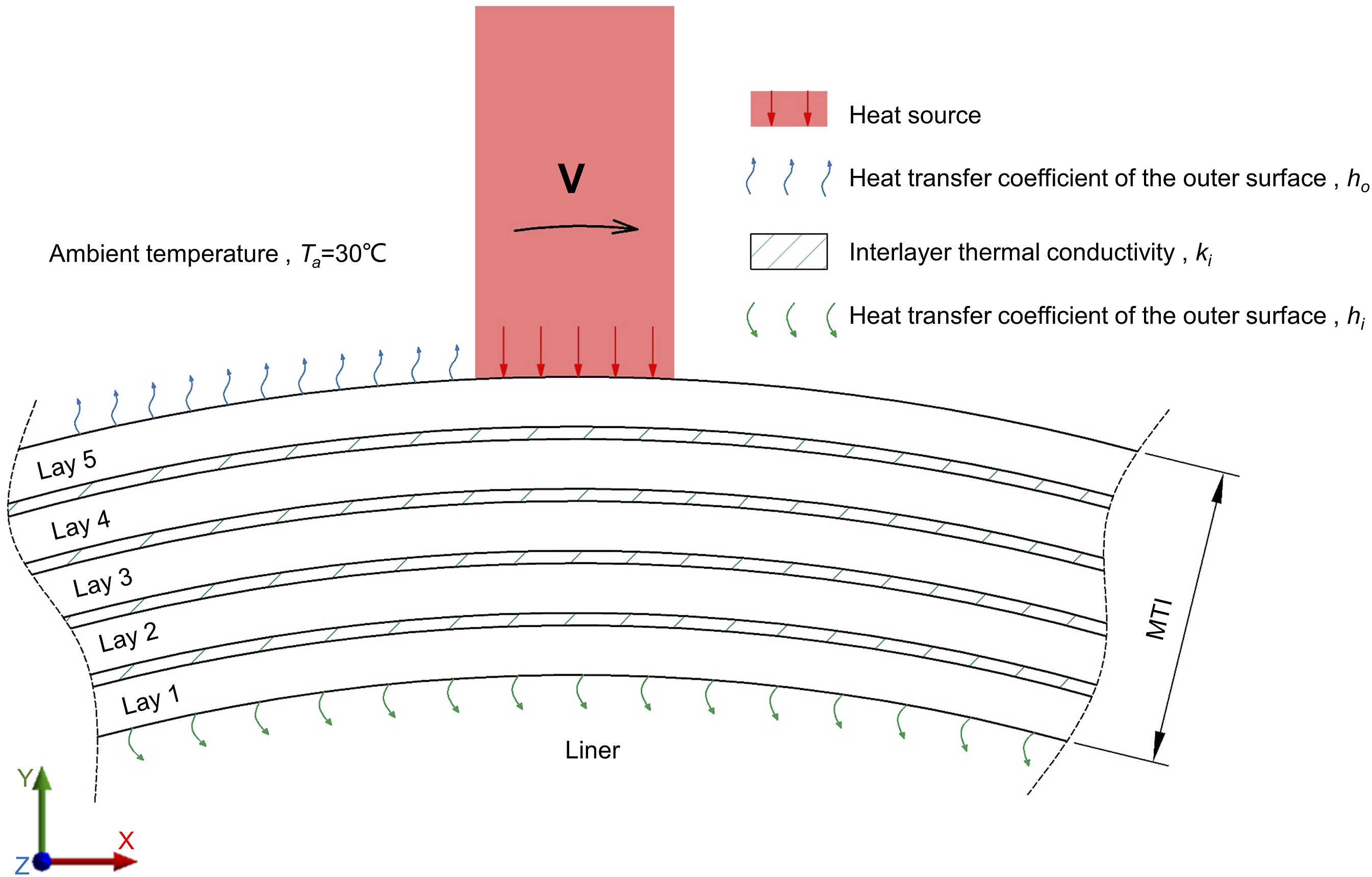
Determination of interlayer thermal resistance
In this paper, the interlayer thermal conductivity of multilayer thermal insulation materials is obtained by comparison and calculation. First, the thermal history of multilayer thermal insulation materials is tested, and then the finite element calculation results of the thermal conductivity between different layers are compared to obtain the interlayer thermal conductivity under the experimental conditions in this paper.
In this experiment, GF/PP material with a low melting point was used to form interlayer bonding and interlayer contact was mainly formed after the hot melting of PP. To obtain interlayer thermal conductivity, two layer structures were prepared by in situ consolidation and winding molding heated by a hot air gun. To avoid experimental errors caused by a large number of layering layers, three-layer layering was used. The layering sequence is GF/GF/CF and Cu/GF/CF respectively, as shown in Figure 7(a) and (b). Experimental measurement of interlayer thermal conductivity: (a) GF/GF/CF layer, (b) GF/Cu/CF layer, (c) Experimental verification results of GF/GF/CF layer, (d) experimental verification results of Cu/GF/CF layer.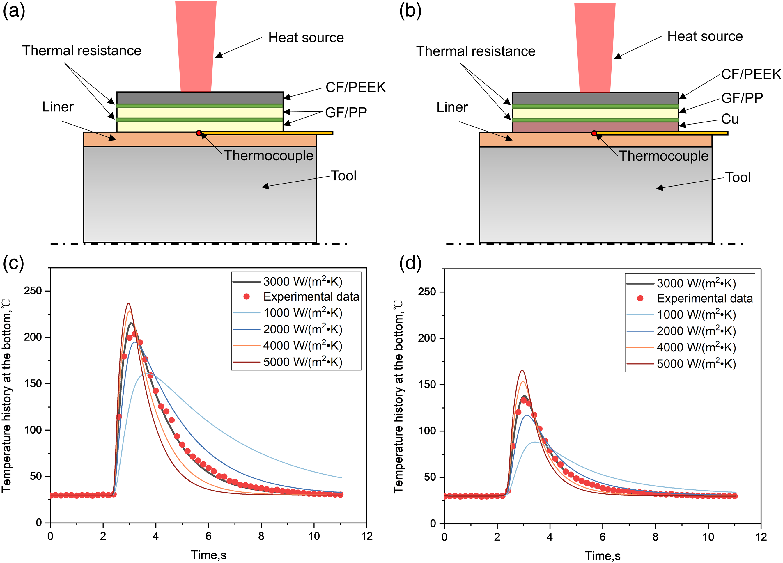
The thermal history of the two layers was tested and compared with the finite element calculation results, and the interlayer thermal conductivity under experimental conditions was obtained, as shown in Figure 7(c) and (d). It can be seen that the interlayer thermal resistance of the two interfaces is about 3000 W/(m2•K) level. The analysis is that both interfaces are provided by GF/PP material bonding, and under the forming conditions adopted in this paper, GF/PP material can achieve good bonding to different materials so that the interlayer thermal conductivity of different paving layers is similar. In the subsequent finite element simulation, the interlayer thermal conductivity was 3000 W/(m2•K).
Results and discussion
MTI has strong designability, and its performance is greatly influenced by the properties of the constituent materials and layering design. To explore the design rules of MTI under the condition of moving heat source heating, this paper uses the finite element moving heat source model to analyze the influence of material properties, layering design, and heat source conditions on the thermal insulation performance of the insulation layer material, and to obtain the selection and design rules of MTI.
Experimental verification of model thermal field
To verify the accuracy of the finite element model of multilayer composite materials, MTI as shown in Figure 4 was prepared in this paper. The laser heating thermal insulation test experiment was carried out, and the corresponding temperature field of the finite element model was calculated. The experimental and finite element calculation results are shown in Figure 8. Experimental verification results of MTI: (a) GF/GF/GF/GF/CF layer, (b) Cu/GF/Cu/GF/CF layer.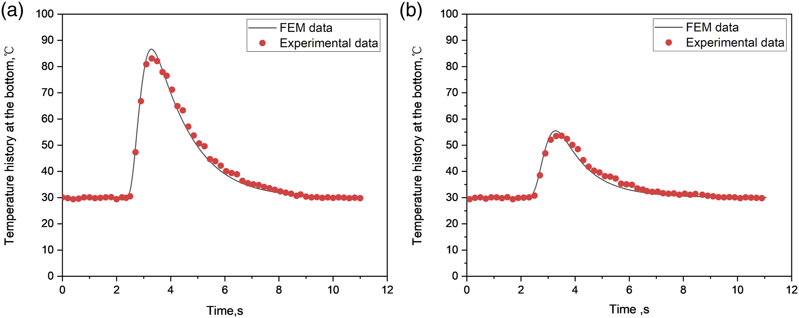
From the comparison of the finite element calculation results and the experimental test results in Figure 8, it can be seen that the finite element calculation results are close to the experimental test results. Among them, the temperature measurement point and curve of the GF/PP layer fit well, but due to the data acquisition frequency of the temperature measuring device, the highest temperature point was not collected, and the experiment with copper-containing MTI had a measured highest temperature lower than the finite element calculation result. Generally speaking, the simulated temperature of the finite element model is close to the measured temperature, and the simulation parameters used in the finite element model are reasonably applicable.
Influence of thermal properties of materials
Figure 9(a) summarizes the thermal insulation effects of MTI containing different materials. It can be seen that the thermal insulation effects of the two composite material laminates are poor and similar, both about 77%. The thermal insulation effects of the MTI with metal are better than those of the two composite materials. Among the metal materials used, MTI containing copper has the best thermal insulation effect, which is 85.4%. MTI containing silver and gold have the next best thermal insulation effects, which are 85.2% and 84.3%, respectively, while the MTI containing titanium has the worse thermal insulation effect, which is 78.4%. It can be seen that high thermal conductivity metal materials have a significant effect on reducing the temperature of the bottom surface, but the thermal insulation effect of MTI with different materials is not only affected by the thermal conductivity of the metal itself. In the calculation group, the thermal conductivity of silver is the highest, but the thermal insulation effect of copper-containing MTI is better than that of MTI containing silver. This indicates that the thermal insulation performance of MTI with the metal does not only depend on the thermal conductivity of the material. Thermal insulation effect of MTI: (a) Thermal insulation effect, (b) maximum temperature by layer, (c) temperature history of the bottom layer.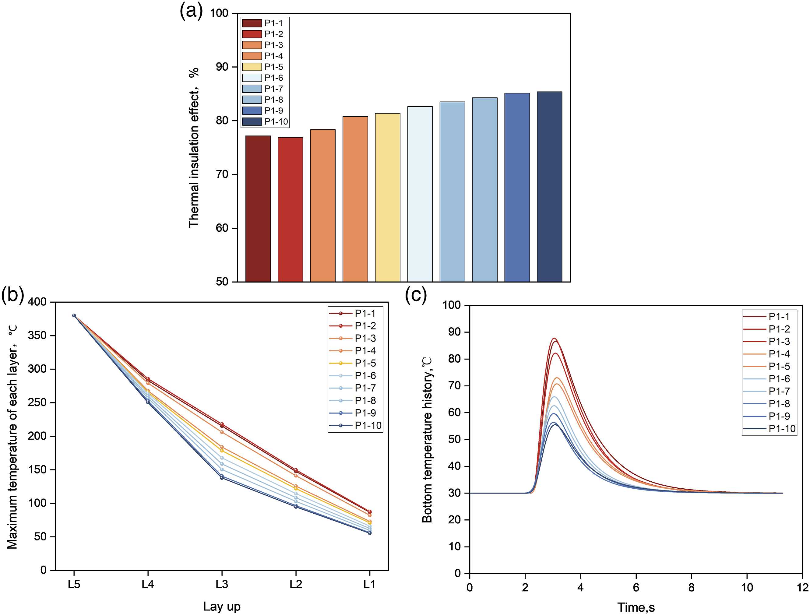
Figure 9(b) and (c) respectively show the highest temperature of each layer of different material layering and the temperature history of the bottom layer. It can be seen from Figure 9(b) that the temperature change slope of metal-containing layering is larger, indicating that the temperature drop of metal-containing layering is faster, especially in the third layer, which is because the third layer is metal layering. The fifth layer is also metal layering, but the cooling is not obvious, which may be due to the heat transfer of the bottom layer of different layering and the small temperature difference. As can be seen from Figure 9(c), metal materials with high thermal conductivity began to heat up earlier, and materials with low specific heat capacity had a faster heating rate, which was analyzed to be caused by rapid in-plane thermal conduction.
A thermal field program of two typical metal-containing materials MTI and composite MTI was taken to analyze the layer-by-layer thermal field distribution. Figure 10 shows the layer-by-layer top view thermal field distribution of MTI when the moving heat source moves to 3s. Thermal field of MTI containing different materials.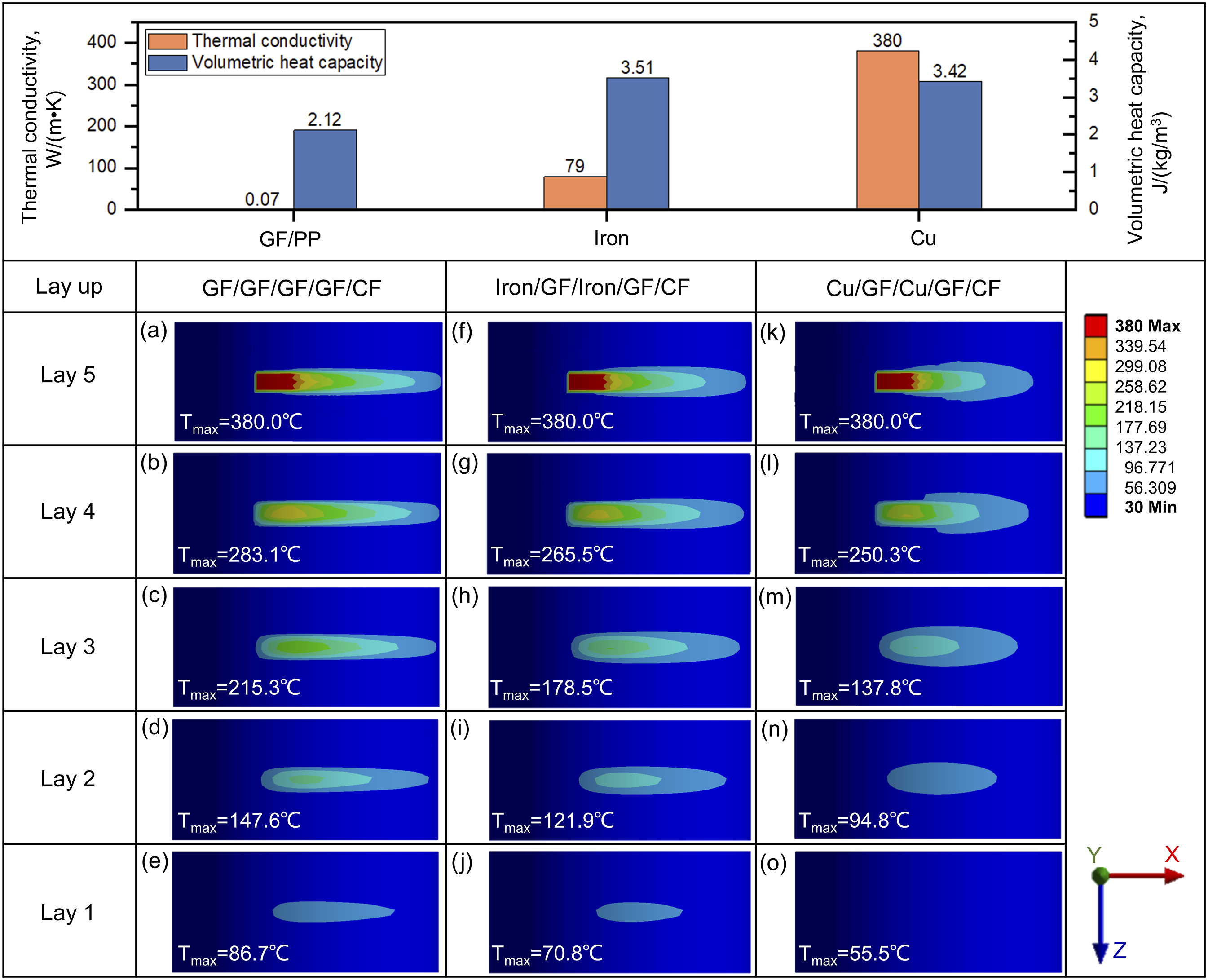
From Figure 10, it can be seen that when the moving heat source heats the MTI containing high thermal conductivity metal materials, the temperature rise area perpendicular to the direction of movement of the heat source in the internal layers of the MTI increases significantly. The high-temperature area in the internal layers of the MTI decreases rapidly, and the thermal field of the internal layers becomes more uniform, with no obvious locally concentrated temperature. This results in a significant reduction in the highest temperature on the bottom surface of the MTI.
It can be seen from the calculation results that the thermal insulation effect of metal-containing multilayer insulation materials is not only affected by the thermal conductivity of the materials. Considering that laminates are adopted in this paper, each layer has a certain thickness, and the purpose of this study is to consider the thinning of the insulation layer. It is necessary to investigate the thermal performance per unit volume of materials, and comprehensively evaluate the thermal insulation effect of different metal material insulation layers by using thermal conductivity and volumetric heat capacity. The thermal insulation effect of 8 groups of metal-containing MTI was analyzed by response surface analysis, and the influence of thermal conductivity and volumetric heat capacity of different metal materials on the thermal insulation effect was analyzed. The response surface obtained was shown in Figure 11(a), the sensitivity analysis was conducted, and the analysis results were shown in Figure 11(b). Thermal properties of metal materials on thermal insulation effect: (a) Response surface analysis, (b) local sensitivity analysis, (c) influence of thermal conductivity of metal materials, (d) influence of volume heat capacity of metal materials.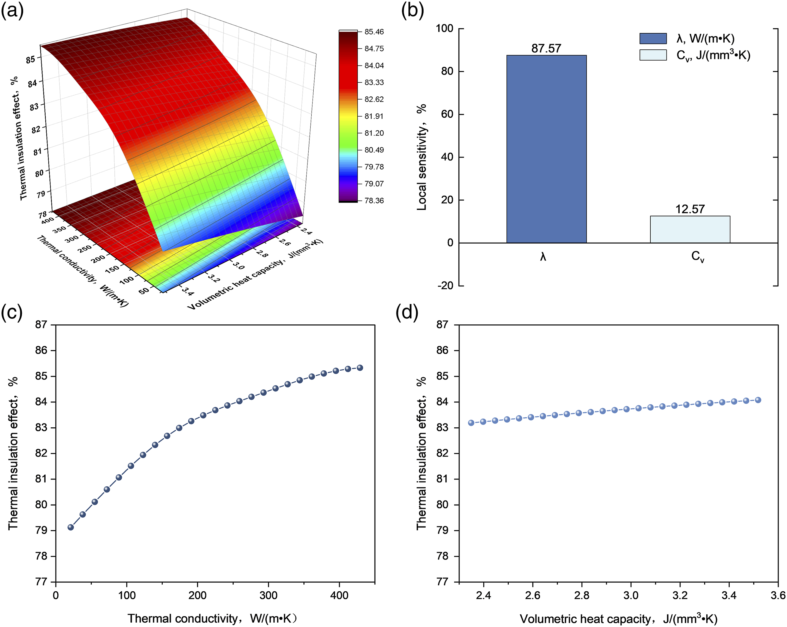
According to the response surface analysis results in Figure 11(a), the thermal insulation effect is significantly improved with the increase of thermal conductivity. As the volume heat capacity increases, so does the thermal insulation effect. According to the local sensitivity analysis in Figure 11(b), the local sensitivity coefficient of thermal conductivity is 87.57%, and the volume heat capacity is 12.57%, indicating that the thermal conductivity of materials has a much greater impact on the thermal insulation effect than the volume heat capacity of materials. The influence of thermal conductivity and volume heat capacity on the thermal insulation effect is analyzed separately. It can be seen from Figure 11(c) and (d) that the influence of thermal conductivity on the thermal insulation effect presents a logarithmic growth trend, and the influence effect is relatively significant. The influence of volume heat capacity on the thermal insulation effect presents a nearly linear law, and the effect is weak.
Influence of laying-up factors
It can be seen from the calculation results of the previous section that the thermal insulation effect of copper is the best among common industrial materials. In this section, the influence of the number, location, and thickness of metal layup on the thermal insulation effect is studied by using copper. Figure 12 shows the thermal insulation effect of MTI composed of multiple layers. Thermal insulation effect of different MTI layers.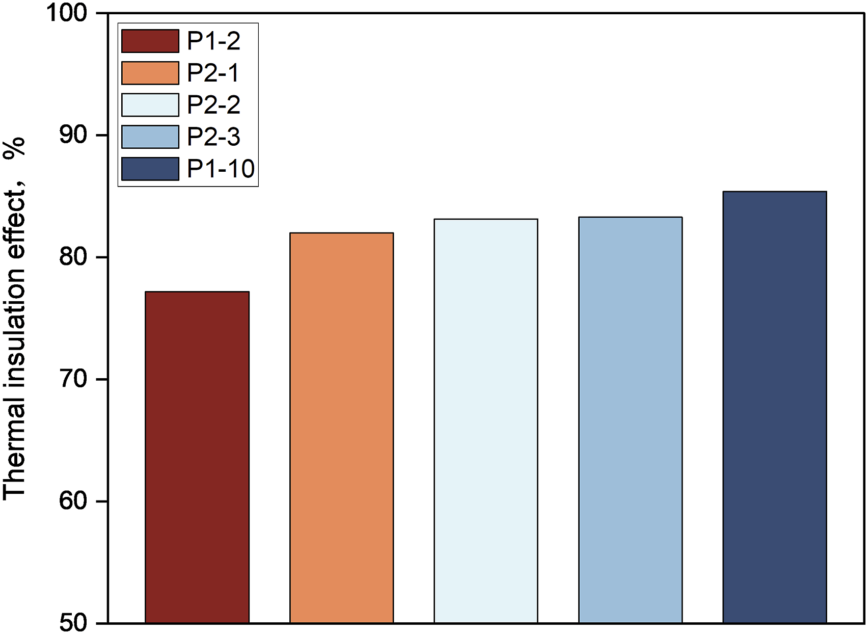
Based on the analysis of the influence of the number of metal material layers, it can be seen from P1-1 and metal-containing lay-up that the lay-up containing only one layer of copper can reduce the bottom temperature from 86.7°C of P1-1 to less than 70°Cso that the thermal insulation effect of multilayer insulation material increases from 77% to 83%. MTI using a single layer of copper can have a better thermal insulation effect. By comparing P2-3 and P1-10 layers, it can be seen that the thermal insulation efficiency of P1-10 layers with two layers of metal copper is 85.4%, and the thermal insulation effect of P1-10 layers is limited compared with MTI containing single-layer metal material.
Analyzing the influence of the position of the metal layers, when comparing the MTI with the same number of metal layers, the thermal insulation effect is better when the metal layers are closer to the heat source. This analysis is partly since the layers closer to the heat source have higher temperatures, which makes the heat flow more fully conducted in the metal layers. The high-temperature area in the metal layers is wider, and the energy consumed by the temperature rise of the metal layers is greater, resulting in less energy entering the inner layers. On the other hand, because the high-temperature area in the metal layer is wider, the high-temperature area in the adjacent layers of other materials is also wider, which reduces the temperature peak.
After that, the influence of layering thickness on the thermal insulation effect is analyzed when the total thickness of multilayer insulation material is the same. The MTI composed of 0.3 mm GF/PP and metal copper is simulated and calculated. The layup is Cu/GF/CF, and the total thickness of the multilayer material is 0.75 mm. The maximum temperature of the bottom layer is 77.9°C, and the thermal insulation effect is 79.5%. Compared with P1-10 layering, it can be seen that, when the total thickness of multilayer insulation material is constant, MTI with a thin single-layer thickness has a better thermal insulation effect. The analysis is that MTI with a thin single-layer thickness has more interlayer interfaces and a significant interlayer thermal resistance effect, which makes MTI with better thermal insulation effect.
By analyzing the layer-by-layer thermal field of MTI at different metal lay-up locations, it can be seen from Figure 13 that the heat field distribution heated by moving heat source is greatly affected by metal lay-up, and metal lay-up makes the transverse (perpendicular to the direction of heat source movement) thermal field diffusion in a plane more significant. In the layer P2-3, the metal layer is close to the surface layer. When the heat-affected zone of the layer is heated by the moving heat source, the transverse distribution of the heat-affected zone along the surface is wide, indicating that the heat dissipation phenomenon in the surface is more significant, so that the bottom layer of the layer has a lower temperature and better heat insulation effect. Thermal field of MTI with different layers.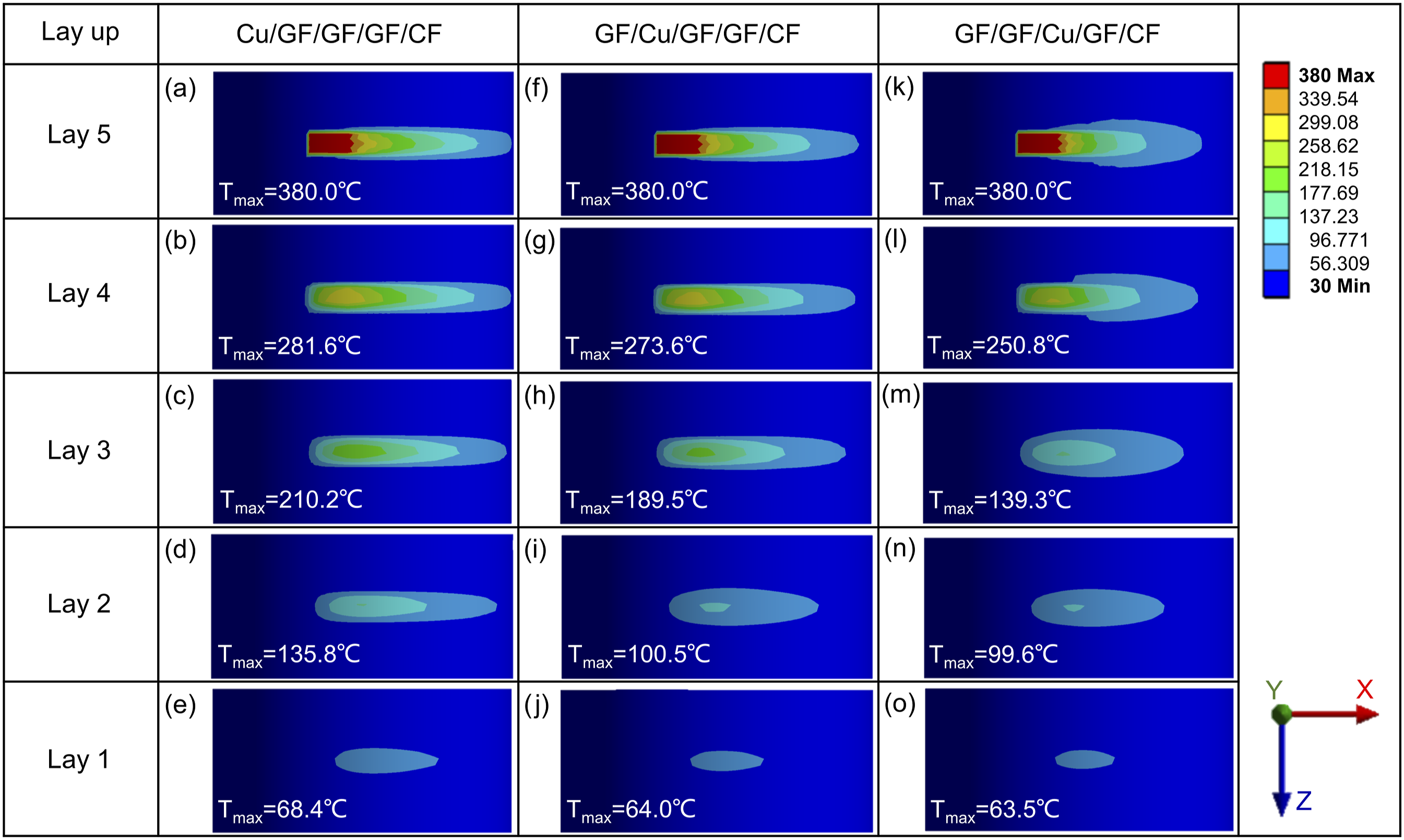
Although the increase of the metal layer will improve the heat insulation effect of the heat insulation layer, the increase and thickening of the copper layer will lead to the weight increase of overlay structure, electromagnetic performance changes, and other problems, which should be considered comprehensively in practical use. Taking the rotor of the motor studied in this paper as an example, due to the high density of the metal layer, it is easy to separate the metal layer from the internal structure layer due to the influence of centrifugal force during the service of the motor rotor. To prevent structural separation, fiber-reinforced composites are often used to apply preload. Moreover, the increase of the metal layer will affect the eddy current loss of the motor, so it is necessary to control the thickness of the metal layer while meeting the heat insulation requirements.
Influence of thermal field conditions
This section discusses the influence of thermal field conditions on the thermal insulation effect of multilayer insulation materials and analyzes the influence of heat source temperature, heat source movement speed, external surface heat transfer, and internal surface heat transfer on the thermal insulation effect of P1-1 and P1-10 laminated MTI.
In the actual molding process, the temperature of the heat source will be set within a suitable range higher than the melting point of the resin and lower than the decomposition temperature of the resin. For the CF/PEEK material studied in this paper, the resin melting point is 343°C, and the initial decomposition temperature of the resin is generally considered to be 400°C. The thermal insulation effect of two typical heat insulation layers at 340°C, 360°C, 380°C and 400°C is analyzed. Figure 14(a) shows the change of thermal insulation effect of two kinds of heat insulation layers with the change of heat source temperature. It can be seen that with the increase of heat source temperature, the thermal insulation effect of the two layers is slightly increased, but the thermal insulation effect of the two layers is not significantly affected by the change of heat source temperature. Influence of thermal field conditions on the insulation effect: (a) influence of heat source temperature, (b) influence of heat source velocity, (c) influence of heat transfer coefficient on the outer surface of MTI, (d) influence of heat transfer coefficient on the inner surface of MTI.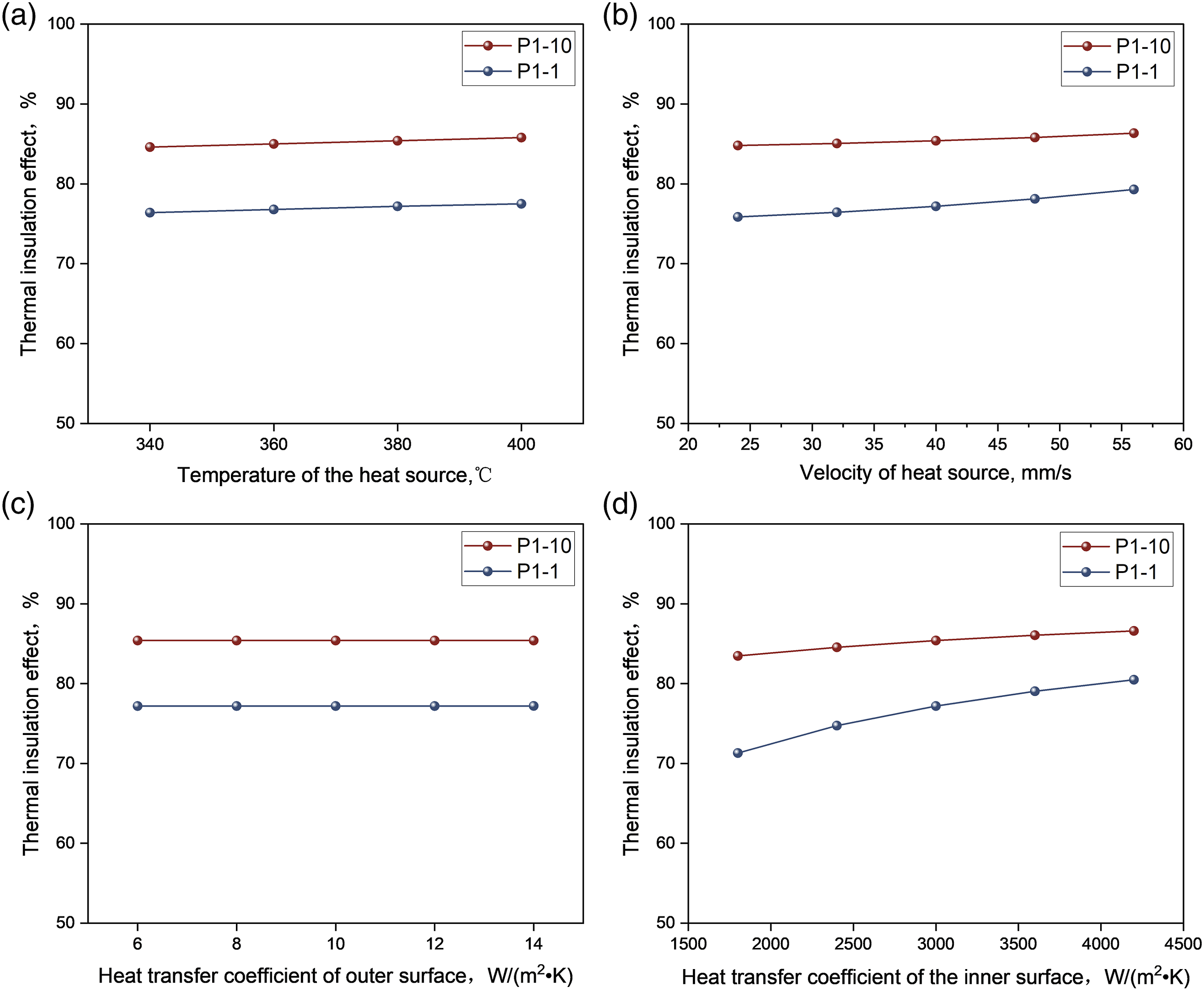
Figure 14(b) shows the heat insulation efficiency of P1-1 and P1-10 layering at heat source moving speeds of 24, 32, 40, 48, and 56 mm/s. It can be seen that the thermal insulation effect of each insulation layer is improved with the increase of laser moving speed. The analysis is that the heating time of the specified position on the surface of the workpiece is reduced with the increase of heat source moving speed. When the heat source temperature is constant, the energy input of the heat source to the outer surface of MTI is reduced, resulting in the overall improvement of the thermal insulation effect.
Figure 14(c) shows the thermal insulation efficiency of P1-1 and P1-10 layers with external surface heat transfer coefficients of 6, 8, 10, 12, and 14 W/(m•K). It can be seen that since the surface of the thermal insulation layer studied in this paper is gas convection heat transfer, its convection heat transfer coefficient is low, and the thermal insulation effect of the two-layered thermal insulation layers is little affected by the convection heat transfer of the outer layer.
Figure 14(d) shows the thermal insulation efficiency of P1-1 and P1-10 layers with internal surface heat transfer coefficients of 1800, 2400, 3000, 3600, and 4800 W/(m•K). It can be seen that when there is heat transfer on the inner surface of the insulation layer, the thermal field and the thermal insulation effect of the insulation layer will be significantly affected. With the increase of the heat transfer coefficient of the inner surface of MTI, the thermal insulation effect of the heat insulation layer is improved, and the heat transfer coefficient of the inner surface of the P1-1 layer is greatly affected. The analysis is that the surface temperature of the inner surface of the P1-1 layer is relatively high. According to the calculation formula of convective heat transfer, q = h (t1-t2), when the temperature difference is large, the convective heat transfer energy is more, which leads to the improvement of the thermal insulation effect.
To investigate the effects of various heat source conditions on the thermal insulation effect, sensitivity analyses were conducted on the heat source conditions parameters for two layers, P1-1 and P1-10, and the analysis results are shown in Figure 15. Sensitivity analysis of thermal field conditions: (a) Sensitivity analysis of P1-1 layering, (b) Sensitivity analysis of P1-10 layering.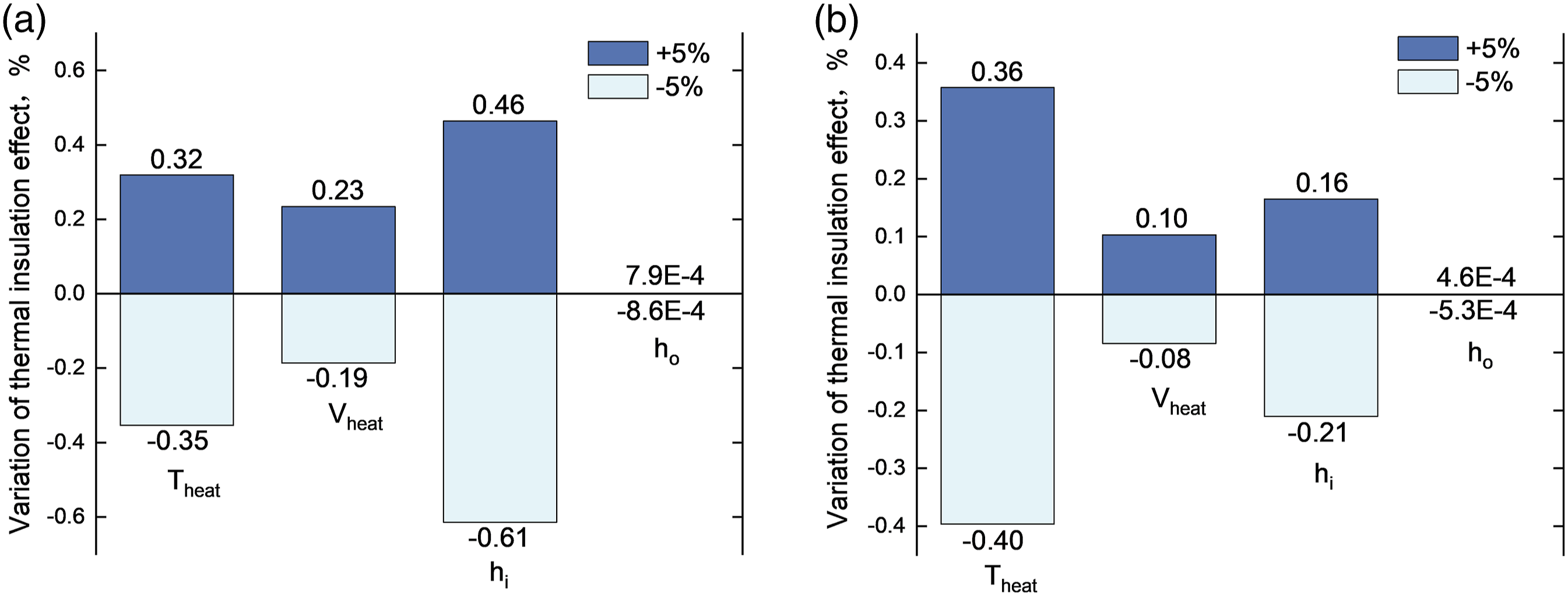
It can be seen from the sensitivity analysis that heats source temperature, heat source moving speed, heat transfer coefficient of the inner surface, and heat transfer coefficient of the outer surface are positively correlated to the effect of the thermal insulation effect. In the current parameter analysis range, the heat dissipation coefficient of the outer surface layer has little influence on the thermal insulation effect, heat source temperature, heat source movement speed, and heat dissipation coefficient of the inner surface have a great influence on thermal insulation effect, among which, P1-1 layer is affected by heat dissipation coefficient of inner surface most. The analysis is that the P1-1 layer has a higher temperature and a larger temperature difference than room temperature. When the heat transfer conditions change, the energy change of the P1-1 layer is greater, so the thermal insulation effect changes more obviously.
Multilayer thermal insulations insulation optimization
Taking the preparation of rotor casing with CF/PEEK, a commonly used high-performance thermoplastic composite material, as an example, the typical molding temperature of CF/PEEK is 380°C, and a rubidium iron boron permanent magnet with a commonly used safe temperature of 150°C was used. Because the magnetic field intensity of the permanent magnet will decrease significantly with increasing distance, to minimize the influence of MTI on the magnetic field intensity of the permanent magnet, MTI needs to be designed as thin as possible. By using a copper-containing MTI and optimizing the layering, insulation design for the formation of the rotor sleeve is achieved.
Figure 16 shows the maximum layer-by-layer temperature of GF/GF/GF/GF/GF/CF layering and Cu/GF/CF layering that meet the thermal insulation requirements. It can be seen from the calculation results that the maximum temperature reduction of each layer of metal insulation material is significantly faster than that of GF/PP composite material. The use of GF/PP material requires 3 layers and a surface layer of CF/PEEK to achieve an appropriate heat insulation effect. When copper is used as thermal insulation material, in addition to the surface layer, only one layer of GF/PP is needed to bond a layer of metal copper to meet the thermal insulation requirements. One layer can be reduced, achieving a 25% reduction in insulation thickness. Optimal design of MTI layer: (a) maximum layer-by-layer temperature of MTI, (b) thinning of MTI layering.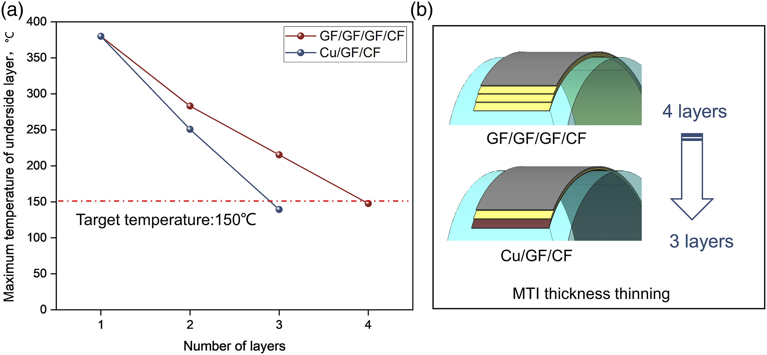
Conclusion
The high-performance thermoplastic composite material laser-assisted in-situ consolidation molding has the advantages of high molding efficiency and the possibility of integrated assembly molding. However, the molding temperature is relatively high, which may cause damage or failure of the assembled components. In this paper, to meet the insulation requirements during the laser-assisted integrated assembly molding process of the motor rotor sleeve, it is proposed to use metal-containing MTI as the insulation layer and utilize the in-plane heat transfer of the metal material to achieve insulation in the thickness direction and reduce the thickness of the insulation layer. A finite element three-dimensional transient heat field model was established, and experiments were conducted to verify the accuracy of the model. The influence of material thermal properties, layer structure, and thermal field conditions on the insulation effect of MTI was analyzed, and the optimization design of the thermal insulation layer was completed for the specific insulation requirements of the motor rotor sleeve. The study presented in this paper shows that: 1. The response surface method was used to analyze the influence of thermal conductivity and volume heat capacity of metal materials on the thermal insulation effect of MTI. It was found that the greater the thermal conductivity and specific heat capacity of the metal material, the more significant the in-plane heat transfer of MTI, resulting in better insulation along the thickness direction. Copper is the material with the best thermal insulation effect among common engineering metal materials, and the thermal insulation effect of copper-containing MTI can reach 85.4%. Local sensitivity analysis shows that the impact of thermal conductivity on insulation performance is much greater than that of specific heat capacity, with a ratio of approximately 7:1. 2. Comparing the number of metal layers, it was found that using a single layer of copper significantly improved the insulation performance compared to GF/PP composite material, increasing the insulation performance from 77.2% to 83.3%. However, increasing the number of copper layers has no obvious effect on the thermal insulation effect. The MTI with a double layer of copper had an insulation performance of 85.4%, which was not much different from that of the MTI with a single layer of copper. Comparing the position of the metal layer, it was found that the closer the metal layer was to the heat source, the better the insulation performance of MTI. Comparing the thickness of a single layer of the metal layer, it was found that when the total thickness of MTI was the same, the thinner the single-layer thickness and the more the number of layers, the more significant the interlayer thermal resistance effect and the better the insulation performance of MTI. 3. Analyzing the influence of thermal field conditions on the insulation effect of MTI, it can be seen that, under the experimental conditions in this article, the heat dissipation conditions on the outer surface had almost no effect on the insulation performance of MTI, and the temperature of the heat source and the speed of the heat source movement had little effect on the insulation performance of MTI. The thermal conductivity of the inner surface of MTI had a greater impact on the insulation performance. 4. According to the 150°C temperature resistance requirement of NdFeB material commonly used in the motor rotor and the 380°C high-temperature molding condition of high-performance thermoplastic composite CF/PEEK, the copper-containing MTI was optimized to achieve 25% thinning of GF/PP thermal insulation material.
The bonding strength of the metal layer and composite material layer is not considered in this study, mainly because the thermal insulation material studied is applied to the rotor sleeve of the motor, the outer layer of the thermal insulation layer is the sleeve structure layer with internal pressure, in the process of service, the thermal insulation layer is always under pressure, the interlayer strength of the thermal insulation material is not high. Existing studies have shown that, in the design of the motor rotor, adding a thin metal copper layer inside the composite sleeve can effectively reduce the overall eddy current loss of the rotor and improve the electromagnetic efficiency of the motor. 36 The thermal insulation layer containing the metallic copper layer explored in this paper has the comprehensive effect of thermal insulation and electromagnetic shielding, and more comprehensive research and design can be done in the future for the versatility of MTI.
Footnotes
Declaration of conflicting interests
The author(s) declared no potential conflicts of interest with respect to the research, authorship, and/or publication of this article.
Funding
The author(s) received no financial support for the research, authorship, and/or publication of this article.