
Abstract
In this study, fly ash (FA) which mainly consists of SiO2, Al2O3, Fe2O3, MgO, and CaO, was used as a synergistic additive (1–5 wt %) to improve the effectiveness of an intumescent flame retardant (IFR) system (25 wt %) in high density polyethylene (HDPE). IFR system composed of ammonium polyphosphate and pentaerythritol (3/1 ratio), and different amounts of FA were incorporated homogeneously into HDPE. Thermogravimetric analyses and thermal conductivity measurements were performed to determine the thermal properties. Meanwhile, limiting oxygen index, UL 94 vertical burning, and cone calorimetry tests were performed to investigate the fire resistance. Furthermore, the effects of IFR/FA additions on the mechanical properties were determined. The experimental results showed that IFR and IFR/FA additions resulted in early degradation with lower rates, and the residual mass values increased due to the char layers and the FA content. Also, IFR addition increased the thermal conductivity coefficient from 0.451 W/mK to 0.462 W/mK and IFR/FA additions further increased the coefficient up to 0.506 W/mK. Although the sample included only 25 wt % IFR could meet the requirements of UL 94 V-2 with a LOI value of 25.0%, 2, 3 and 4 wt % FA additions satisfied the criteria of UL 94 V-0 with a LOI value of 26.6%. In addition, the cone calorimeter results revealed that the peak heat release rates and total heat released values decreased with IFR (25 wt %) and FA (2, 3, and 4 wt %) additions. Furthermore, CO, CO2, and soot emissions of the composites significantly reduced with respect to HDPE. The NO increased with IFR additions due to the nitrogen content of APP. 25% IFR addition caused decreases in the tensile strength, tensile modulus, and Izod impact strength. However, FA additions slightly enhanced the mechanical properties of HDPE/IFR composite.
Introduction
Polyethylene (PE) is one of the most widely used thermoplastic materials in different areas such as aviation, automotive, healthcare, and packaging. However, it is a flammable material, and the flame rapidly spreads over the entire material. Therefore, it is required to improve the fire retardancy of PE to continue its usage in certain areas or to find new usage areas.1,2
In this concept, different kinds of flame retardant materials have been used to enhance the thermal and flame resistances of PE. Ghomi et al. 3 presented a review article on the flame retardancy of PE-based composite materials. Effects of different flame retardants including nitrogen, phosphorous, melamine, boron, inorganic hydroxides, and silicon were compared with explaining the fire retardancy mechanisms. Although halogenated flame retardants are effective flame retardants, they evolve toxic gases in the thermal degradation and burning of PE. Therefore, halogen-free flame retardants have been investigated for PE-based composite materials.4–12
Among the halogen-free flame retardants, intumescent flame retardant systems, which are composed of a carbon donor, an acid source, and a spumific agent, have been investigated for different polymers.13–18 When a polymer including an intumescent flame retardant system is exposed to a heat source, the system generates a carbonaceous char layer on the surface of the polymer. The char layer decreases heat and mass transfers between the polymer and the heat source. Meanwhile, the char layer restricts the diffusion of oxygen into the polymer and combustible gas transfer from the polymer toward the flame. It is known that the effectiveness of the intumescent flame retardant system depends on the strength of the generated char layer. Many studies, which have used different compounds in different ratios, have been carried out to enhance the effectiveness of different intumescent flame retardant systems for PE.19–28
Moreover, different fillers like clay, zirconium-based compounds, zinc borate, zeolite, and kaolin were used in the production of polyethylene composite materials with/without intumescent flame retardant systems.29–34 It was determined that there were two reasons for using the fillers. The first one was to reduce the production costs of the composites. Because the fillers were cheaper than the intumescent flame retardant systems and PE. The second one was to increase the effectiveness of the intumescent flame retardant systems.
Meanwhile, fly ashes, which are by-products of pulverized coal-fired power plants, were also used to improve the properties of polyethylene composite materials.35–44 In addition, the use of fly ash as a filler has environmental and economic advantages. 45 Since the chemical compositions and physical properties of fly ashes may vary depending on the coal and the combustion systems, different results were reported on the effects of fly ash additions on mechanical, thermal, and burning properties. Although fly ashes could be used directly without any surface modification in polymers,46,47 it should be pointed out that particle size reduction and surface modification of fly ashes are fairly useful for compatibility of the fly ash in polymer interfaces.37,43,48–52 In general, it was reported that certain amounts of fly ashes improved the mechanical properties, thermal and fire resistances of the materials.53–56
Fly ashes were used with intumescent flame retardant systems in polypropylene and polyurethane-based composite materials.57–59 It was reported that the char layer formed by the intumescent flame retardant system was further strengthened by the fly ashes and the fire resistances of the polypropylene and polyurethane-based composites were enhanced. However, no study was found in the literature related to the use of fly ash with an intumescent flame retardant system in polyethylene composites.
In this study, the effects of fly ash additions (1–5 wt %) on the thermal resistance, mechanical properties, and fire retardancy of high density polyethylene composites including 25 wt % an intumescent flame retardant system composed of ammonium polyphosphate and pentaerythritol (3/1 ratio) were investigated with the extensive experimental studies. To the best of the authors’ knowledge, this study presents the synergistic effects of fly ash and intumescent flame retardant combinations in high density polyethylene for the first time in the literature.
Materials and methods
Raw materials
The high density polyethylene, PETILEN YY I668, (HDPE) granulated formed material was procured from Petkim Co. Ltd. (Turkey). Exolit AP 423 ammonium polyphosphate (APP) which is largely insoluble in water was kindly supplied by Clariant (Turkey). Its crystal modification is phase II and its average particle size is 8 µm. Pentaerythritol (PER), which is a non-hygroscopic white crystalline powder with a particle size below 75 µm, was obtained from MKS Marmara Integrated Chemistry Industry Co. (Turkey).
The fly ash (FA) was obtained from Tuncbilek Thermal Power Plant (Turkey) fired with the pulverized lignite coal mined in Tuncbilek district (Turkey). FA mainly consists of SiO2 (57.4%), Al2O3 (18.1%), Fe2O3 (12.2%), MgO (4.2%), and CaO (4.0%) and it is classified as F CLASS. 3-Aminopropyltriethoxysilane, NEVOSIL S 230 (APTES) was kindly supplied by Ultrakim Chemistry Industry Co. (Turkey).
Sieving, size reduction and surface treatment of the fly ash
The particle size reduction and the surface treatment of FA were required to satisfy the interfacial compatibility of FA in the polyethylene matrix. Firstly, the carbon residues and larger particles in FA obtained from the power station were removed by using a sieve (100 μm), and the residuals were discarded. After sieving, FA was dried in an oven at 105°C for 24 h to remove the moisture. The particle size reduction of FA was carried out by using a planetary ball mill (model: SFM-1, MTI Corp., USA). Zirconia pots and 10 mm diameter zirconia balls were used in the milling process. The weight ratio of zirconia balls to FA was 10:1. The rotational speed was kept constant at 400 r/min throughout the 5-h process. To prevent agglomeration and remove heat generation, a processing program in which the rotation direction of the planetary system changes in half-hourly periods was applied.60–64 The particle size distributions of the raw and the milled fly ashes, which were determined by using a Mastersizer 2000, are shown in Figure 1. The size distribution of the raw fly ash appears in a wide range. However, it is seen that the grinding made a remarkable reduction in the size. All particles became less than 10 µm and the d (0.5) was found to be 1.536 µm. Particle size distribution before and after grinding.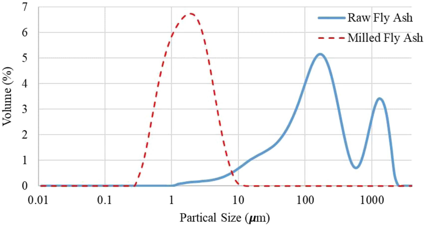
FA was silanated with a 3-Aminopropyltriethoxysilane (APTES) coupling agent in a solution. The amount of the agent used in the process was 2 wt% of FA.65,66 The agent was added to the ethyl alcohol/water solution (95/5 v/v), and they were mixed continuously with a mechanical mixer for 15 min. Thereafter, FA was poured into the solution including the agent, and the mixture was stirred for an additional 45 min. Then, the solvents were removed under vacuum by using an evaporator at 60°C for approximately 1 h. Finally, FA was kept in a ventilated oven at 70°C for 24 h to ensure complete dryness. 44
Preparation of HDPE based composite samples
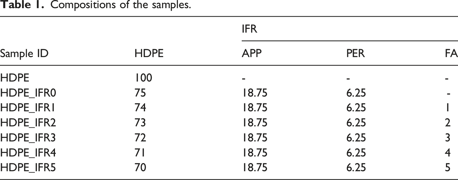
Compositions of the samples.
Sample morphology
The morphology of the fracture surfaces of HDPE and its composites was examined by a Zeiss Gemini Supra 40 VP brand scanning electron microscope (SEM) equipped with EDX spectrometers. SEM pictures of the samples coated with gold/palladium were taken at the voltage of 10 kV.
Thermogravimetric analysis
A Perkin-Elmer Diamond analyzer was used to determine the thermal degradation behavior of HDPE and its composites. The samples (10 ± 0.2 mg) in alumina ceramic crucibles were analyzed between 30°C and 1000°C with a temperature rise of 20°C/min in a nitrogen environment (200 ml/min).
Thermal conductivity test
A Kyoto QTM-500 Quick Thermal Conductivity Meter using the hot wire method was used to measure the thermal conductivity values of the samples according to the ASTM C1113 standard. The samples' surface dimensions and thickness were 100 mm*100 mm and 20 mm, respectively.
Vertical burning test (UL 94) and Limiting Oxygen Index test (LOI)
A vertical burning instrument was used for measuring the comparative burning characteristics of the samples in a vertical position according to UL 94 and ASTM D 3801 standards. The dimensions (length * width * thickness) of the samples were 125 mm*13 mm * 3.2 mm. A Qualitest LOI equipment was used to determine the LOI values of the samples according to ASTM D2863 standard. The dimensions of the samples were 125 mm × 6.5 mm × 3.2 mm for LOI tests.
Cone calorimeter test
A cone calorimeter instrument was used to determine detailed burning characteristics of the samples according to ASTM E-1354 standard. The dimensions of the samples were 100 mm × 100 mm × 6 mm. In the tests, an external heat flux of 35 kW/m2 was horizontally exposed to the sample surface (100 mm*100 mm), and the temperatures, the mass loss, soot, CO2, CO, NO, and O2 emissions were recorded in 1 s increment by using a special program.
Mechanical properties
An Instron 8801 Servohydraulic Fatigue Testing System was used for the tensile tests at a crosshead speed of 50 mm/min in accordance with ASTM D 638. A Ceast Resil Impactor was used to determine the Izod impact strengths of the notched samples in accordance with ASTM D256. HDPE and its composites were conditioned at 23 ± 2°C at a relative humidity of 50 ± 5% for 24 h before all tests.
Results and discussion
SEM and EDX results of the samples
Figure 2 shows the SEM images of the fracture sections of the samples. The surface of HDPE is smooth and featureless. Meanwhile, it is seen that IFR and IFR/FA particles were homogeneously distributed inside the matrixes without significant agglomeration. As it is known, the homogeneous distribution of the particles is important for improving the thermal and fire resistances and preventing deterioration of the mechanical properties.
67
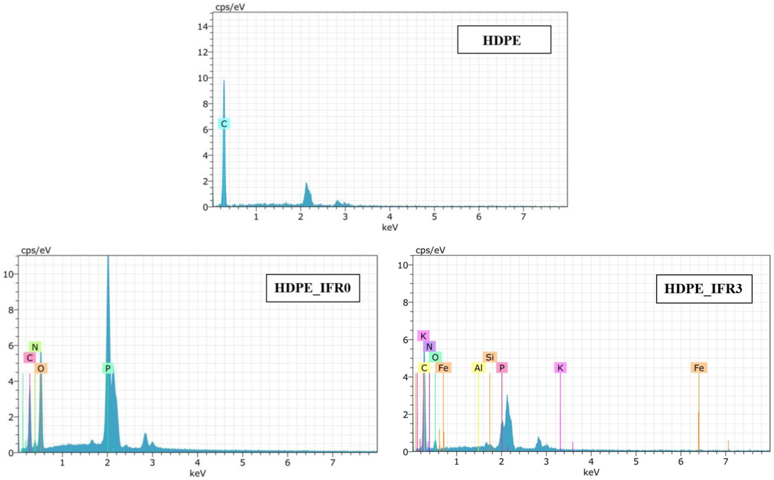
Also, the EDX results of HDPE, HDPE_IFR0, and HDPE_IFR3 were given in Figure 3. Before undergoing SEM and EDX analyses, the samples were coated with gold/palladium (80/20). Peaks that appeared near 2 keV and 3 keV were attributed to the gold and the palladium coatings, respectively.68,69 Therefore, these peaks were not considered in the analyses of the composites. Although only carbon appeared in the EDX result of HDPE, phosphor (P), nitrogen (N), and oxygen (O), which were seen in the EDX result of HDPE_IFR0, indicate APP and PER in the matrix. In addition, the elements (Si, Fe, Al, K) that appeared in the EDX result of HDPE_IFR_3 indicate FA in the matrix. SEM micrographs of the samples (1000 ×). EDX results of HDPE, HDPE_IFR0, and HDPE_IFR3.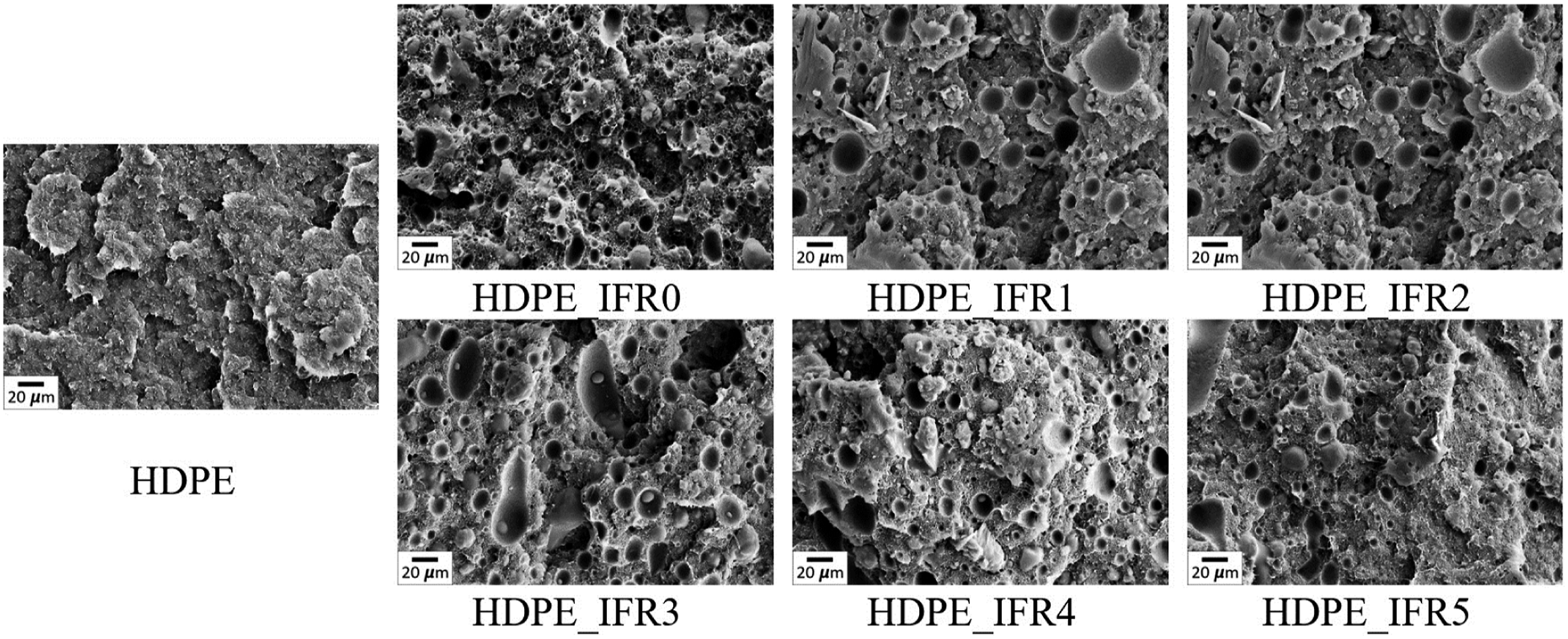
Thermogravimetric analyses of the samples
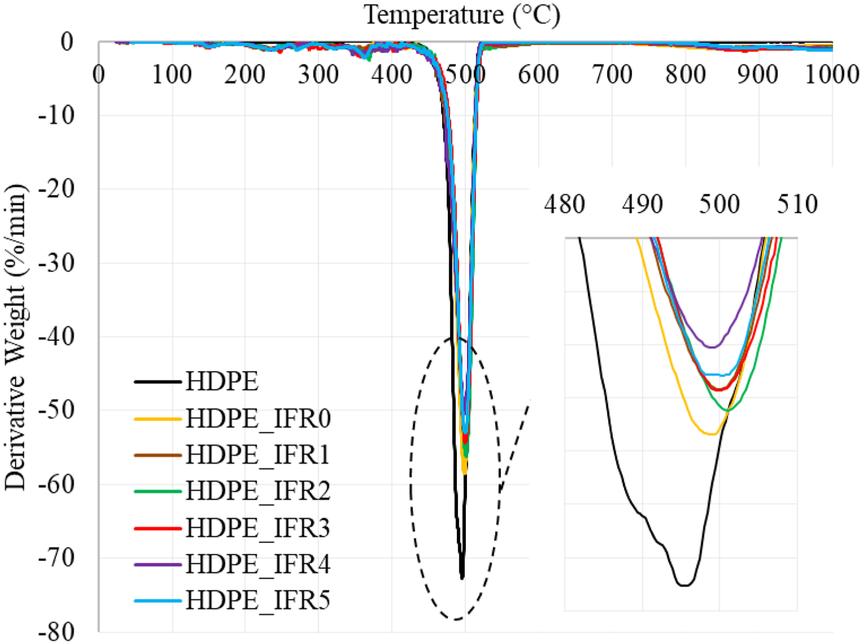
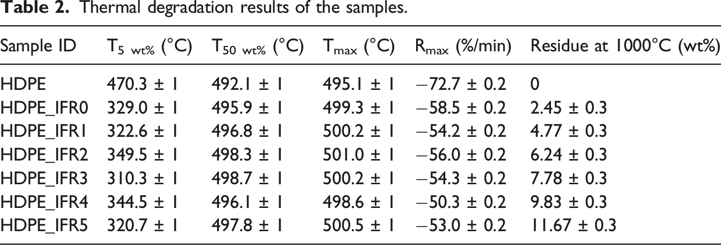
Thermogravimetric analyses of the samples were carried out under a nitrogen atmosphere. The weight and derivative weight losses of the samples are shown in Figures 4 and 5, respectively. In addition, some characteristic values, which are the temperatures at 5% and 50% weight losses (T5 wt%, T50 wt%), the maximum weight loss temperatures and rates (Tmax, Rmax), and the residues at 1000°C, are given in Table 2. HDPE had a one-step degradation behavior between 430°C and 520°C without a residue. The maximum degradation temperature and rate were determined as 495.1°C and 72.7%/min, respectively. However, the composites including 25% IFR started to degrade around 140°C due to the early degradation of PER and the degradation continued with the degradation of APP.
70
The degradations of APP and PER generated a carbonaceous charred layer which slightly increased the maximum degradation temperature to 499.3°C and decreased the maximum rate by 19.5%.
71
Also, it was determined that FA additions slightly further increased the maximum degradation temperatures and decreased the maximum rate by 30.8%. In addition, the residues of composites at 1000°C increased with the additions of IFR and FA. While the residue of HPDE_IFR0 was determined as 2.45%, the residue of HDPE_IFR5 (5 wt % FA) became 11.67%. Weight losses of the samples. Derivative weight losses of the samples. Thermal degradation results of the samples.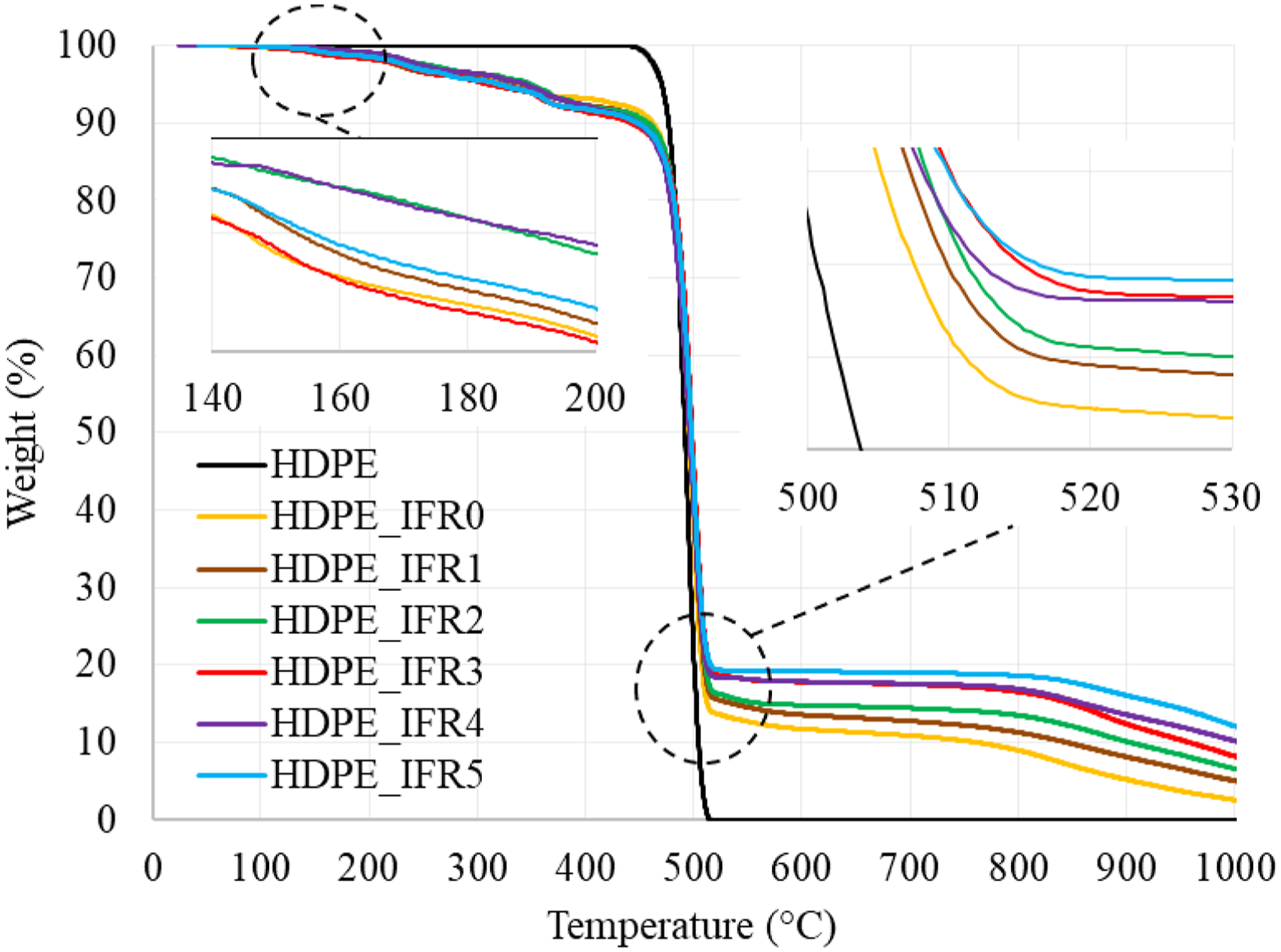
Thermal conductivity of the samples
The thermal conductivity coefficients of HDPE and its composites are compared in Figure 6. The thermal conductivity coefficient of HDPE was determined as 0.451 W/mK. Meanwhile, 25% IFR addition increased the coefficient from 0.451 W/mK to 0.462 W/mK. Also, FA additions further increased the coefficients. The increases were proportional to the amounts of FA additions.
42
The maximum coefficient was determined as 0.506 W/mK for HDPE_IFR5. Thermal conductivity values of the samples. 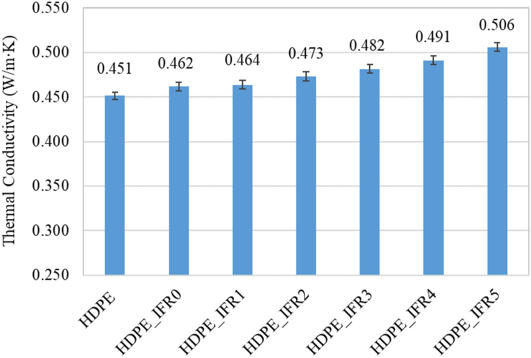
UL 94 vertical burning and limiting oxygen index (LOI) tests of the samples
UL 94 V and LOI test results.
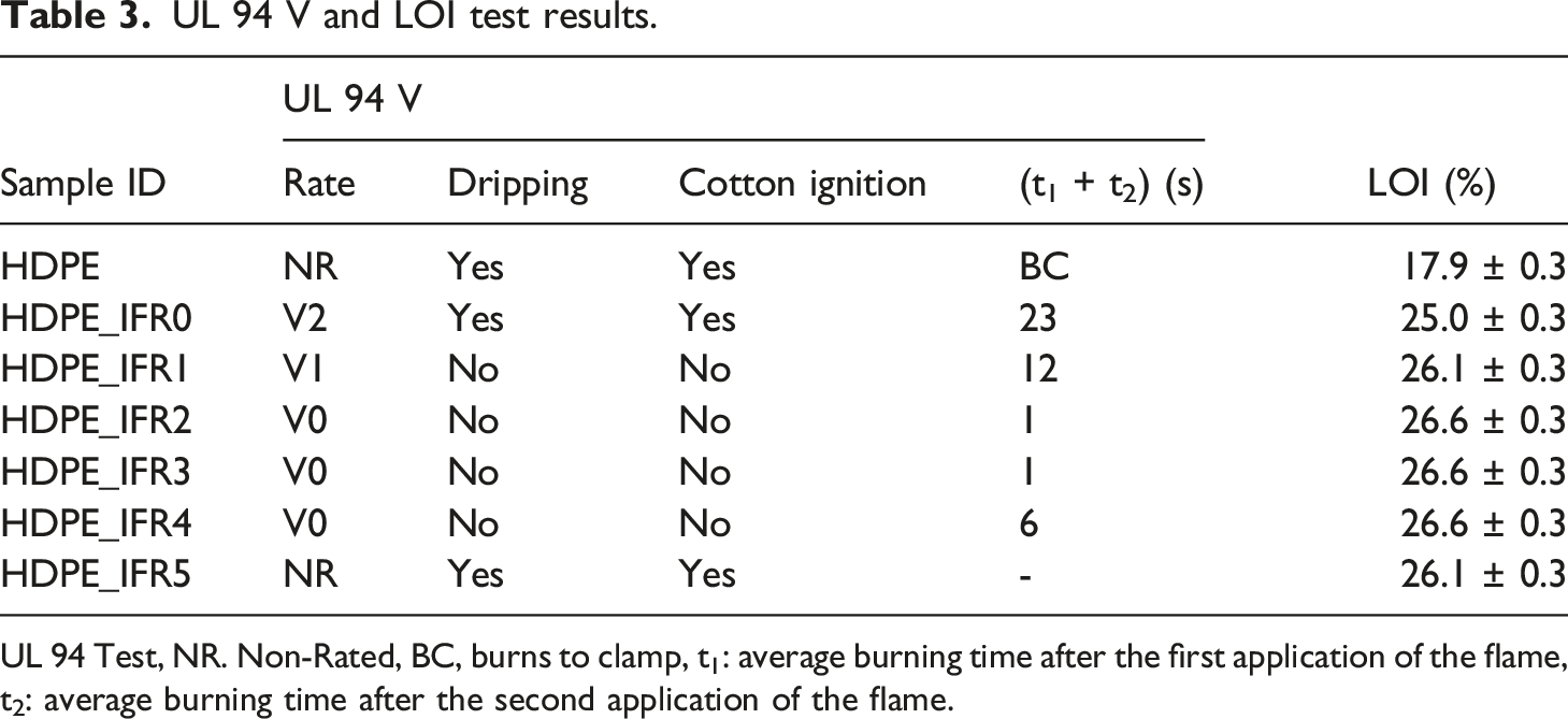
UL 94 Test, NR. Non-Rated, BC, burns to clamp, t1: average burning time after the first application of the flame, t2: average burning time after the second application of the flame.
HDPE is a flammable material and the LOI value of HDPE was found to be 17.9%. Meanwhile, it completely burned with the dripping of the melting droplets and the cotton ignition and was not rated (NR) in the UL 94 vertical burning test. Although 25% IFR addition increased the LOI value from 17.9% to 25.0%, it was not enough for the composite to achieve V-0 rating in the UL 94 test. HDPE_IFR0, which partially burned with the dripping and cotton ignition phenomenon, barely met the requirements of the UL 94 V-2 rating. In this case, it is required to increase the amount of IFR or find an additive that can generate a synergistic effect with IFR. 26
In this study, FA was used as a synergistic additive, and FA additions into HDPE including 25% IFR enhanced the flammability and burning resistances of the composites. 1 wt % FA addition increased the LOI value from 25.0% to 26.1% and caused the composite to meet UL 94 V-1 rating. Although the dripping and the cotton ignition did not occur in the test, the average of the total burning time (t1 + t2) was a little more than 10 s and the V-0 rating could not be satisfied. Meanwhile, 2 wt %, 3 wt %, and 4 wt % FA additions slightly increased the LOI value from 26.1% to 26.6% and satisfied the requirements of the UL 94 V-0 rating. It is thought that 2 wt %, 3 wt %, and 4 wt % FA additions resulted in compact char layers which enhance the flame resistances of the composites.57,70 However, increasing the amount of FA to 5 wt % negatively affected the flammability and fire resistance. HPDE_IFR5 was not rated (NR) in the UL 94 vertical burning test and its LOI value was determined as 26.1%.
The images of the HDPE based composites after the UL 94 vertical burning test are shown in Figure 7. Since HDPE completely burned during the test, the image of HDPE is not shown in the figure. The char layers at the ends of the samples including FA, except 5 wt % FA addition, are visible. It is thought that 5 wt % FA addition prevented the formation and expansion of the effective char layer.
72
Images of the composites after UL 94 vertical burning tests.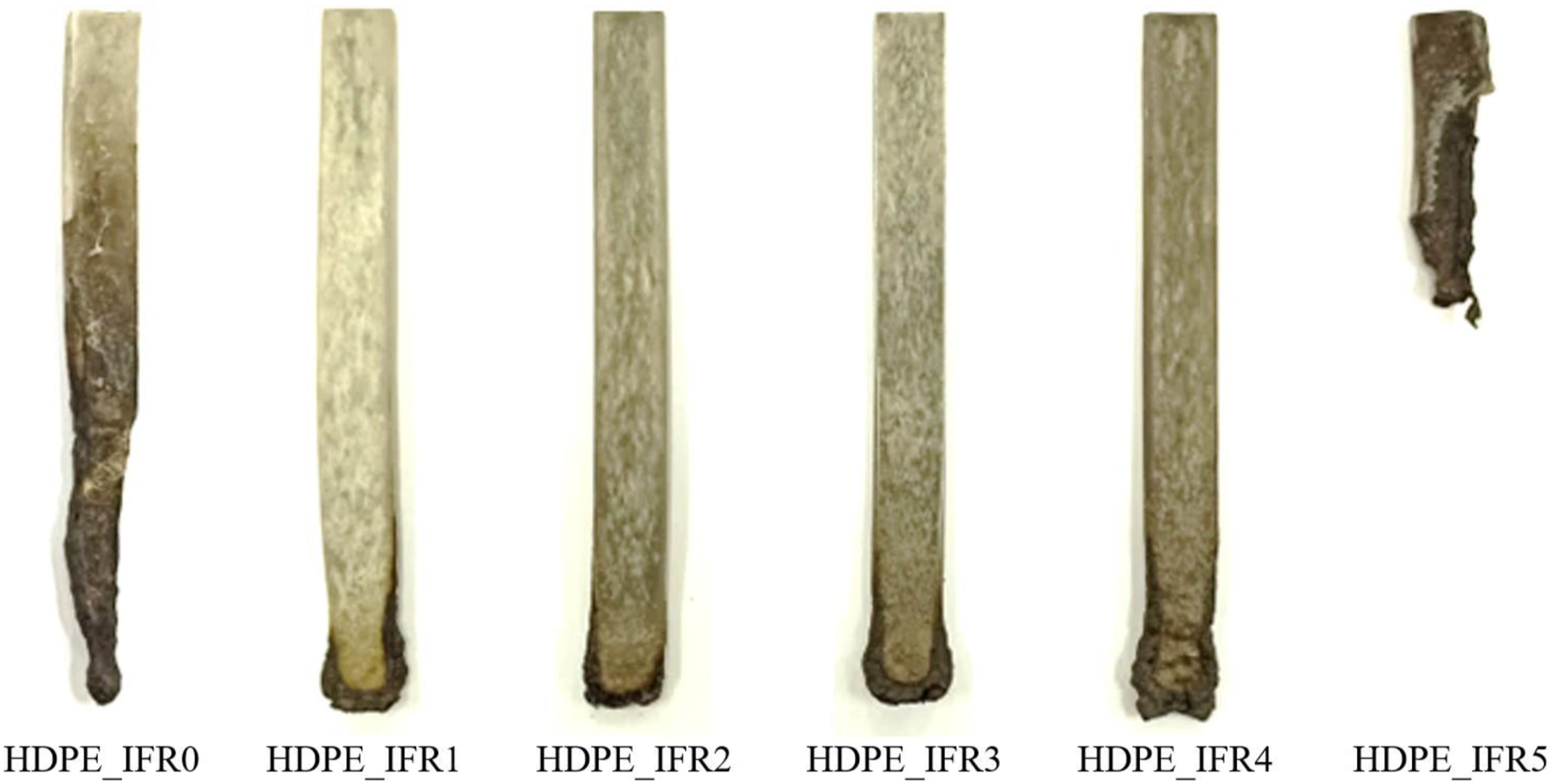
The underlying cause for this can be attributed to various composite material parameters, especially those with intumescent flame retardant systems. Alongi et al. 13 reported that one of the important parameters affecting the formation of an intumescent char is the melt viscosity of the composite matrix during combustion. Meanwhile, it was pointed out that the melt viscosity is one of the key parameters that has a strong influence on the thickness and internal structure of the char layer. 73 The effective char layer can be obtained with the optimal melt viscosity: low enough to allow residue expansion, yet high enough to solidify the foam-like bubble structure.13,74–76 Typically, inorganic fillers, used as synergists in intumescent polymer systems, increases the melt viscosity of the matrix.74,76 An increased viscosity, up to a point, facilitates the generation of a dense char with enhanced mechanical strength, limiting volatile release and hindering heat penetration. The factors, which are thermal insulation, char structure and strength, collectively determine the barrier’s effectiveness and the fire retardancy of the composites.
For the PP/IFR-FA samples, FA additions, up to 5 wt %, were beneficial, causing a rise in the melt viscosities that led to dense char layers which trapped the degradation gases and enhanced the intumescence. This improved the fire resistances of the composites. However, further increasing of FA loading resulted in increasing of the melt viscosity and hindered the intumescence.77–79 Consequently, the effective char layer could not be generated at the right time and the fire resistance of the composite reduced.
Figure 8 shows the images of HDPE and its composites after the LOI tests. In contrast to the UL 94 test where the flame is applied from below for two 10 s intervals, the LOI test introduces the flame at the top of the sample, leading to a downward flame spread. Therefore, the post-test appearances of the samples from the LOI tests differed from those of the UL 94 tests. In the meantime, unlike other composites, notable intumescence and char layer formation could not be observed at the tip of the composite containing 5 wt % FA (HDPE_IFR5) after the ignition. This further supported the aforementioned explanations. Images of HDPE and its composites after the LOI tests.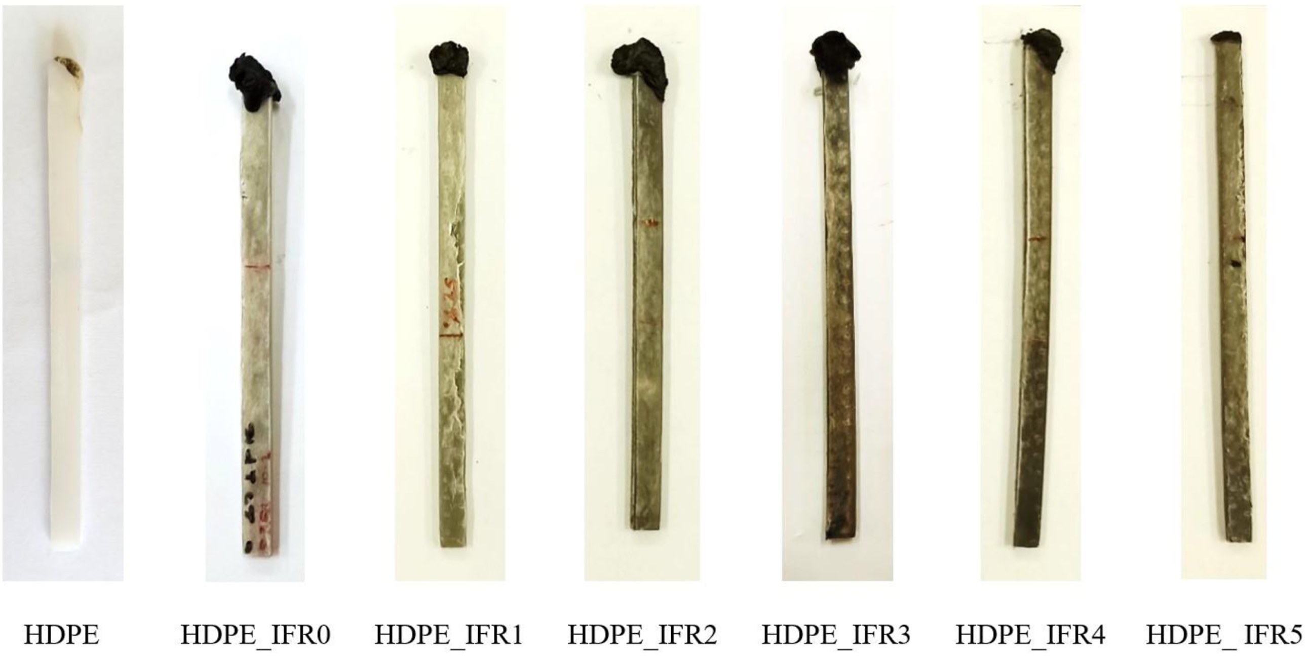
In essence, 1- 4 wt % FA additions generated synergistic effects with IFR and enhance the flame resistance of the composites, 5 wt % FA addition resulted in an antagonistic effect on flame retardancy and deteriorated both flammability and flame resistance of the composite.72,80
Cone calorimeter tests of the samples
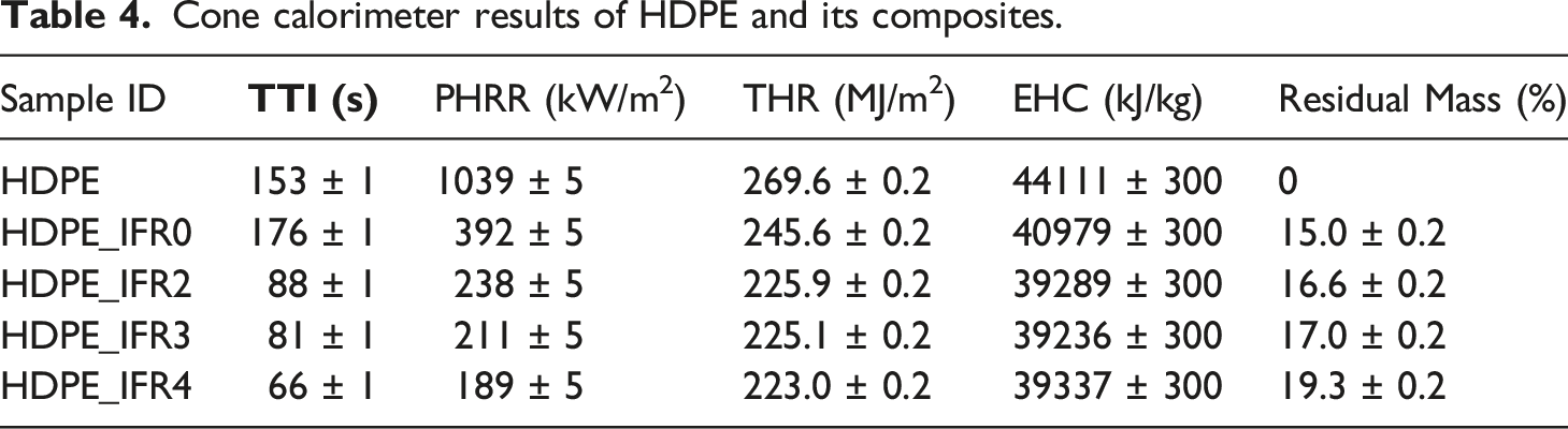
Cone calorimeter results of HDPE and its composites.
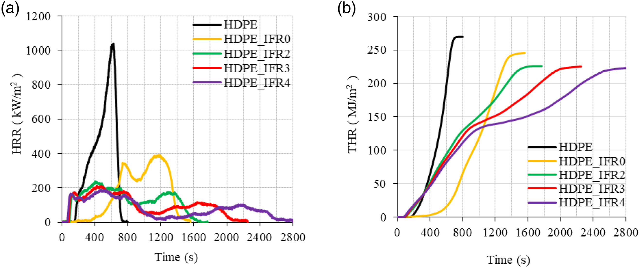
(a) HRR and (b) THR values of the samples.
However, the composite including 25 wt % IFR (HDPE_IFR0) revealed fairly different combustion characteristics. The TTI slightly increased with the addition of 25 wt % IFR. It was observed that the surface of the sample expanded and a thin intumescent layer which reduced the release of flammable gases from the samples was generated. After the ignition, the sample burned slowly for a certain time. Since the layer was not strong enough to stop the combustion, the HRR started to increase. Similar results were obtained by Jiang et al. 83 in the burning of low-density polyethylene composite including the microencapsulated ammonium polyphosphate, the microencapsulated aluminum hypophosphite with polyurea, and the pentaerythritol. Two HRR peaks were observed during the combustion of HDPE_IFR0. The first HRR peak was generated before the formation of the dense char layer. Since the dense char layer acted as a barrier between the flame and the composite reducing the heat and the mass transfer, it led to a decrease in the HRR. However, the cracking of the char layer and the increase in the pyrolysis rate of the composite caused the second HRR peak. 28 The values of the first and the second HRR peaks were lower than those of HDPE. Meanwhile, the THR value was determined as 245.6 kJ/m2 which is 8.9% less than that of HDPE.
The combustion characteristics of the samples including FA (HDPE_IFR2, HDPE_IFR3, and HDPE_IFR4) were different from those of HDPE_IFR0. FA additions (2 wt %, 3 wt %, and 4 wt %) led to increasing pyrolysis rates of the composites and decreased the TTI values. After the ignitions, the composites burned rapidly, and the compact char layers were formed. Although the char layers partially cracked and the HRR values increased, then the char layers were formed and resulted in stabilized HRR values and then decreasing HRR values. It is thought that FA additions reinforced the char layers which improved the fire resistance of the composite.
57
The PHRR values of the samples including FA decreased in proportion to FA content. 2 wt %, 3 wt %, and 4 wt % FA additions decreased the PHRR values by 39.3%, 46.2%, and 51.8% concerning the PHRR of HDPE_IFR0, respectively. Meanwhile, the THR values decreased by 8.0, 8.3, and 9.2%. Although the samples including FA started to burn earlier than HDPE_IFR0, then the burning rates of the samples decreased, and the burning times prolonged up to 2800 s with FA additions. In addition, the residual masses increased with FA additions. Figure 10 compares the mass losses, and the mass loss rates (MLR) of HDPE and its composites. In parallel to the HRR and THR variations, the mass loss of HDPE rapidly occurred with higher rates without any residual mass. Although HDPE_IFR0 ignited somewhat late and burned slowly at the initial stage of the combustion with lower mass loss rates, then there were two regions in the mass loss with higher mass loss rates. Although FA additions resulted in higher mass loss rates at the beginning of the combustion, the formed char layers slowed down the burning and caused decreases in mass loss rates. (a) Mass loss and (b) MLR of the samples.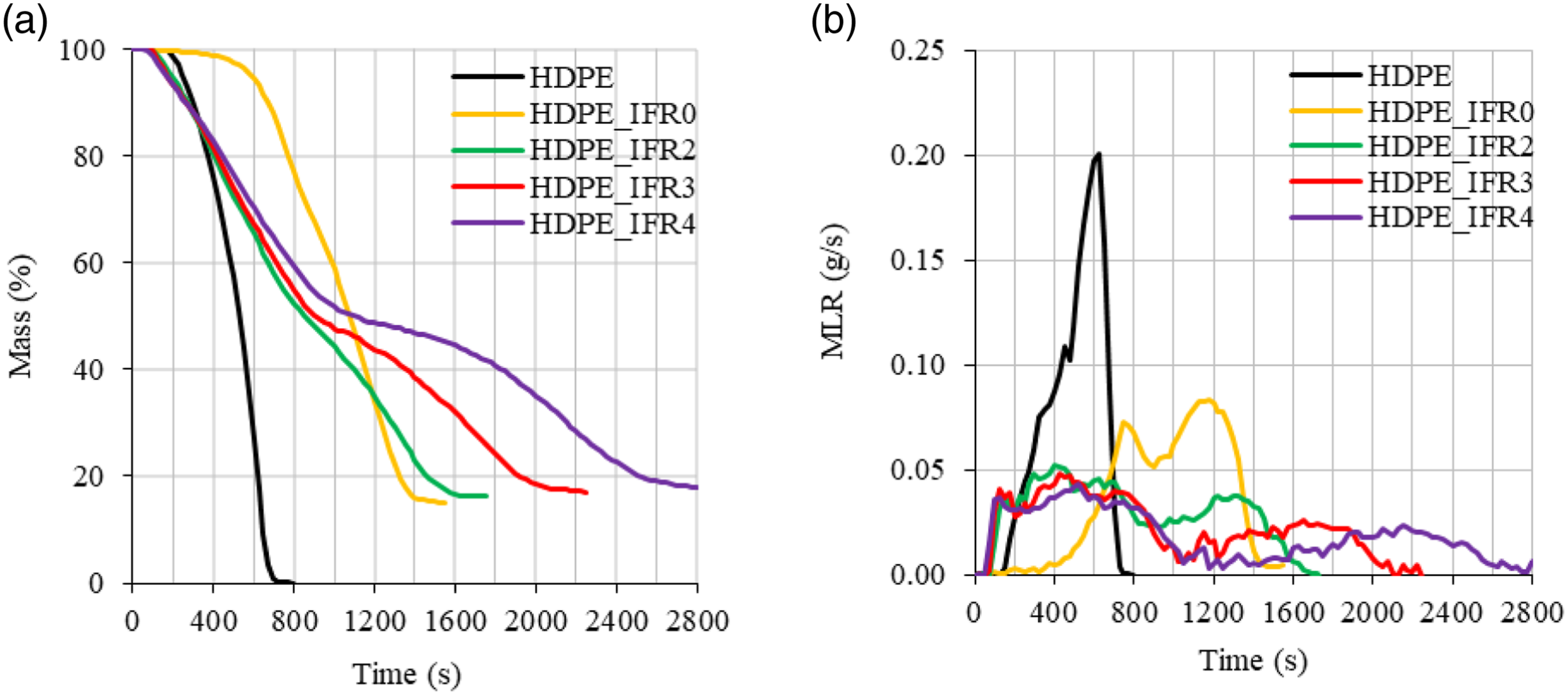
The extinction coefficient (soot), CO, CO2, and NO emissions of the samples are compared in Figure 11. CO and soot, which are formed because of the incomplete burning of combustible materials, are important harmful emissions that cause poisoning in real fires. The generations of CO and soot were delayed and decreased in HDPE_IFR0 burning. However, FA additions further reduced the soot and CO emissions (Figure 11(a) and (b)). Figure 11(c) compares the CO2 emissions of the samples. The CO2 emissions are directly related to the combustion of carbon-based materials. The CO2 variations of the samples were fairly similar to the HRR variations. The NO emissions of the samples are compared in Figure 11(d). Although HDPE does not include nitrogen, small amounts of NO were seen in the emissions due to thermal NO formation. Also, NO formations of the composites were found to be higher than that of HDPE. The increases can be explained by the nitrogen content of APP, which caused the formation of fuel NO. Meanwhile, peak NO values of the samples including FA were lower than that of HDPE_IFR0. This can be explained by the lower PHRR and lower combustion temperatures.
59
(a) The extinction coefficient, (b) CO, (c) CO2, and (d) NO emissions of the samples.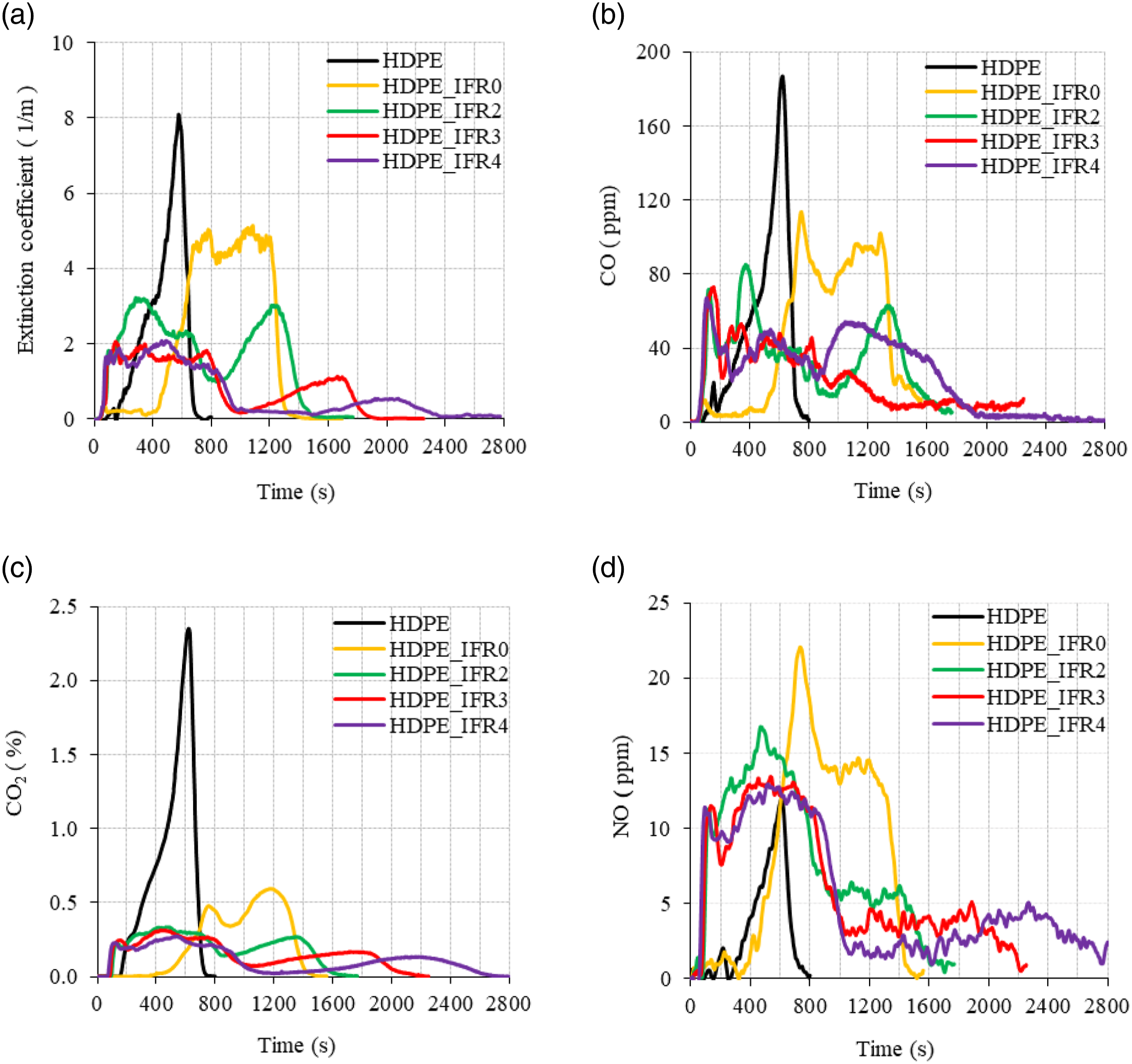
The photographs of HDPE and its composites after the cone calorimeter tests are shown in Figure 12. As previously noted, HDPE burned entirely, leaving no residue after the test. In contrast, the burning of HDPE_IFR0, HDPE_IFR2, HDPE_IFR3, and HDPE_IFR4 resulted in char residues of 15.0%, 16.6%, 17.0%, and 19.3%, respectively. The char layer of HDPE_IFR0 exhibited some cracks, which affected the effectiveness of the char layer. Nonetheless, the other composites including both IFR and FA presented more cohesive char layers. It is thought that the inclusion of FA strengthened the char layer generated by IFR, subsequently enhancing the fire resistances of the composites.
28
Photographs of HDPE and its composites after the cone calorimeter tests.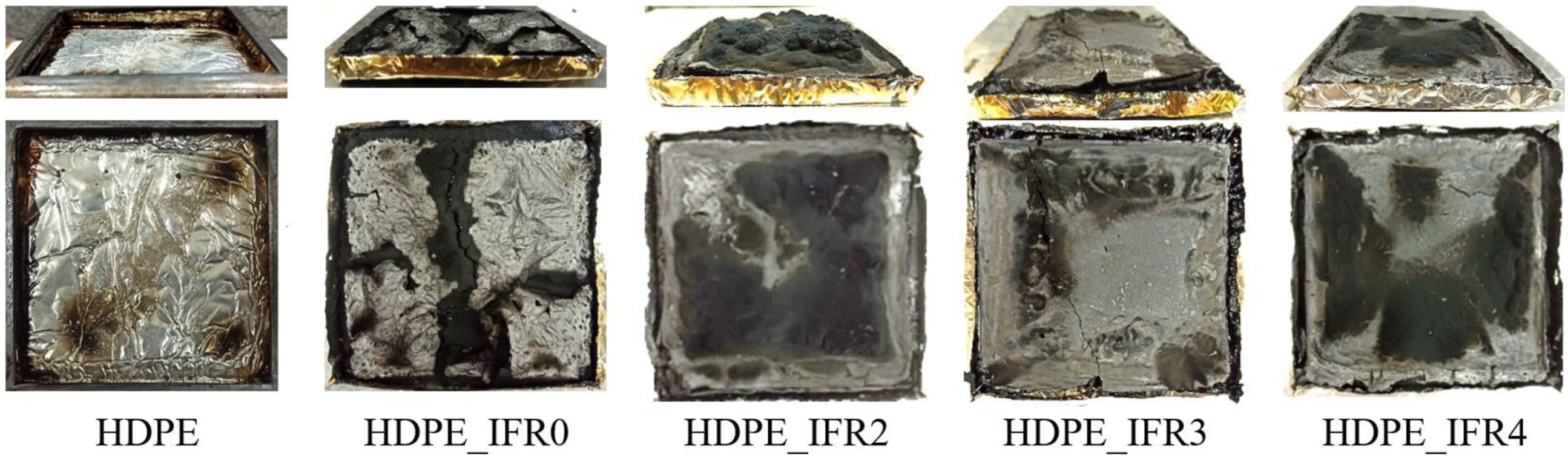
To further investigate the flame retardant mechanism and discern the correlation between the intumescent char layers’ morphology and the flame-retardant performance of the composites, the morphological structures of char residues of HDPE_IFR0, HDPE_IFR2, HDPE_IFR3 and HDPE_IFR4 composites were analyzed by SEM at a magnification of 100 ×. These images are displayed in Figure 13. There are significant differences between the SEM images of HDPE_IFR0 and the others. Beyond the visible cracks, open pores unseen in Figure 12, were identified on the HDPE_IFR0 surface. These cracks and pores, indicative of a weaker char layer, permitted a measurable amount of heat and mass (oxygen and pyrolysis gases) transfer between the flame and the matrix.
84
Consequently, the addition of 25 wt % IFR only offered a modest enhancement in the composite's fire resistance, a fact corroborated by the UL 94, LOI, and cone calorimeter results. In contrast, HDPE_IFR2, HDPE_IFR3, and HDPE_IFR4 residuals displayed denser and more uniform char layers. While minor cracks and voids were present on their surfaces, these imperfections were minimal and sparse. The overall integrity of the char residues remained largely undistorted, showcasing a marked improvement in the strength and barrier attributes of the char layer—suggesting superior flame retardancy.
85
SEM images of the residuals (100 ×).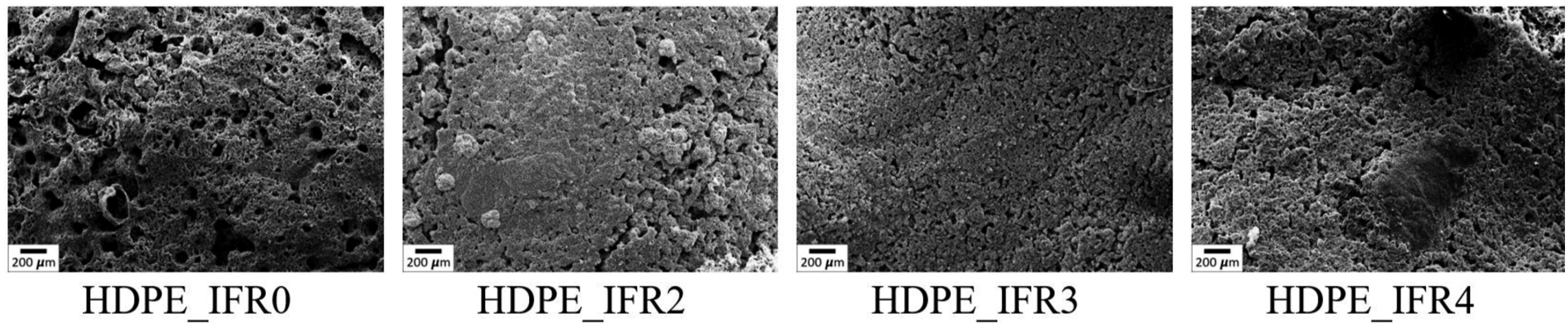
To elucidate the synergistic mechanism between FA and IFR, EDX analyses were also conducted to study the composition of the char layers. The results are presented in Figure 14. The char residue of HDPE_IFR0 comprised elements C, O, N, and P, suggesting that the char layer, enriched with phosphorus and nitrogen, was formed by IFR. In contrast, the EDX spectra of char residues from HDPE_IFR2, HDPE_IFR3, and HDPE_IFR4 showed not only C, O, P, and N but also additional elements such as Si, Fe, Al, Mg, Ca, K, and Ti. This suggests that the compounds of FA predominantly accumulated within the intumescent char layers. It is believed that degradation gases, particularly ammonia from APP, transported FA particles to the char surfaces during combustion and intumescence.
86
EDX results of the residuals.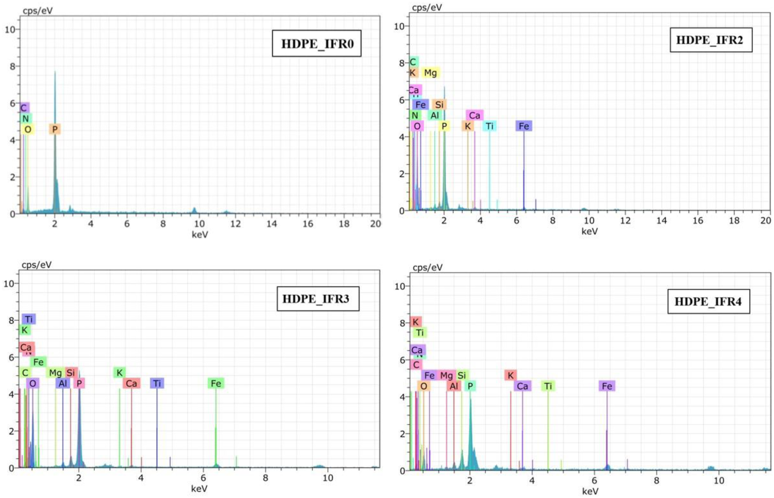
The morphological observations combined with EDX analyses of the residuals suggest that the synergistic effect mechanism between IFR and FA mainly lies in the condensed phase. Due to improved compactness and continuity, the charred layer acts as a barrier, mitigating heat and gas transfer between the polymer matrix and its surface. This, in effect, reduces the heat release and smoke emissions during combustion.87,88 The aforementioned experimental results substantiate this claim.
Mechanical properties of the samples
In general, additives that were used to enhance thermal and fire resistance weaken the mechanical properties of polymers. 83 Therefore, it is required to determine the changes in the mechanical properties for deciding the application areas of polymers.
The tensile strength and modulus of the samples are shown in Figures 15 and 16, respectively. The tensile strength and modulus of HDPE were measured as 29.5 MPa and 954 MPa, respectively. 25% IFR addition resulted in decreases in these values. The tensile strength and modulus values of HDPE_IFR0 were determined as 19.6 MPa and 694 MPa, respectively. These reductions can be explained by the partially poor compatibility of IFR in the matrix.89–92 However, the silanated FA additions into the matrix slightly increased these values with respect to HDPE_IFR0. It is thought that the silanated FA partially enhanced the compatibility between the additives and HDPE.
83
It is noteworthy that APTES (3-amino propyl triethoxy silane), which was used for silanization of FA, is a versatile amino-functional coupling agent and the silicon-containing portion of the molecule could provide strong bonding to the substrates. Therefore, it acted as a bonding or bridging agent for improving the adhesion across the interfaces of FA and HDPE/IFR. Also, previous studies highlighted that surface treatments with silane coupling agents could enhance the interfacial and mechanical properties of polymer composites.93–96 The maximum tensile strength and modulus were determined with 3 wt % FA addition. The tensile strength and modulus values of HDPE_IFR3 were determined as 22.0 MPa and 755 MPa, respectively. Tensile strength of HDPE and its composites. Tensile modulus of HDPE and its composites.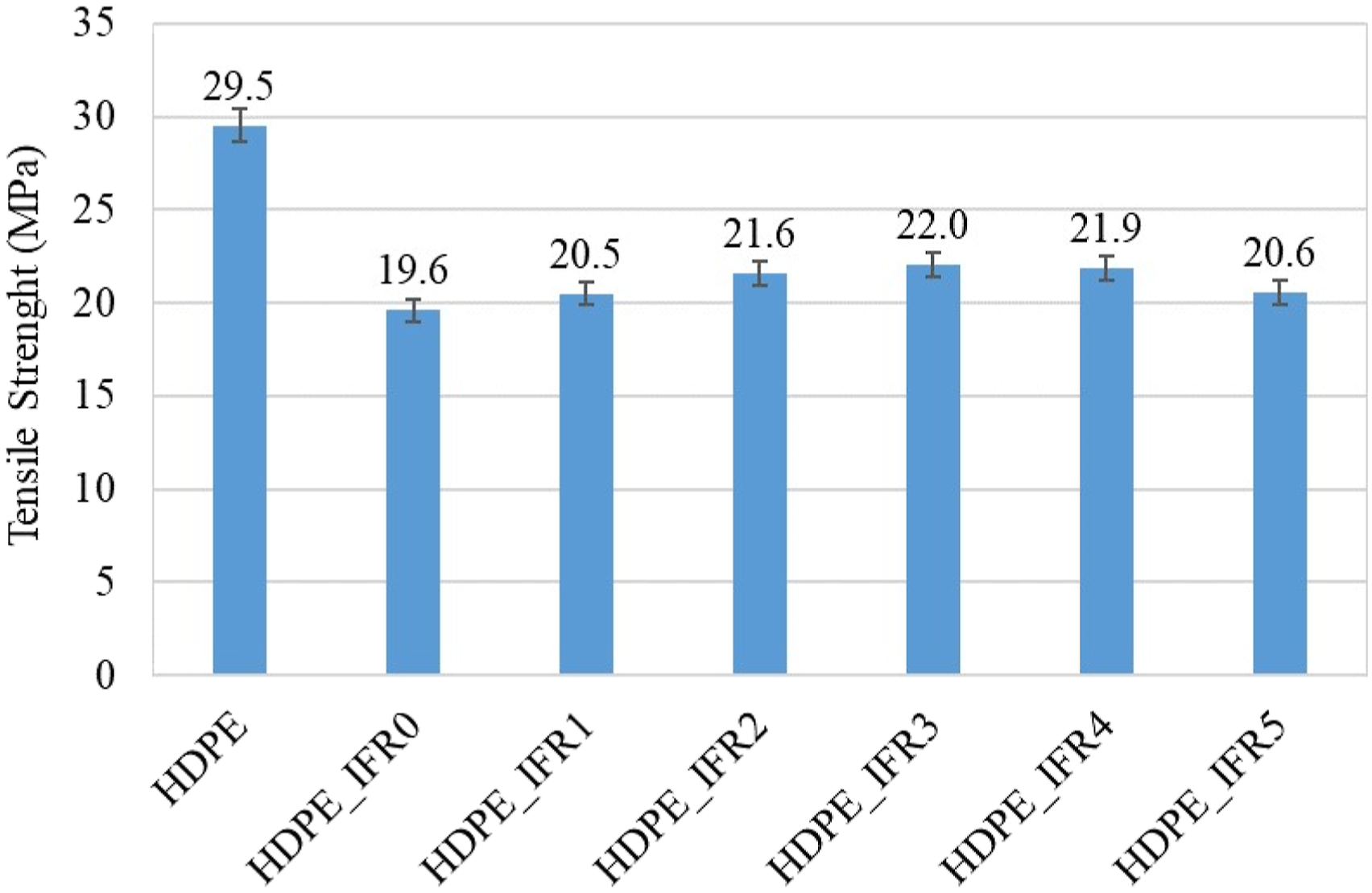
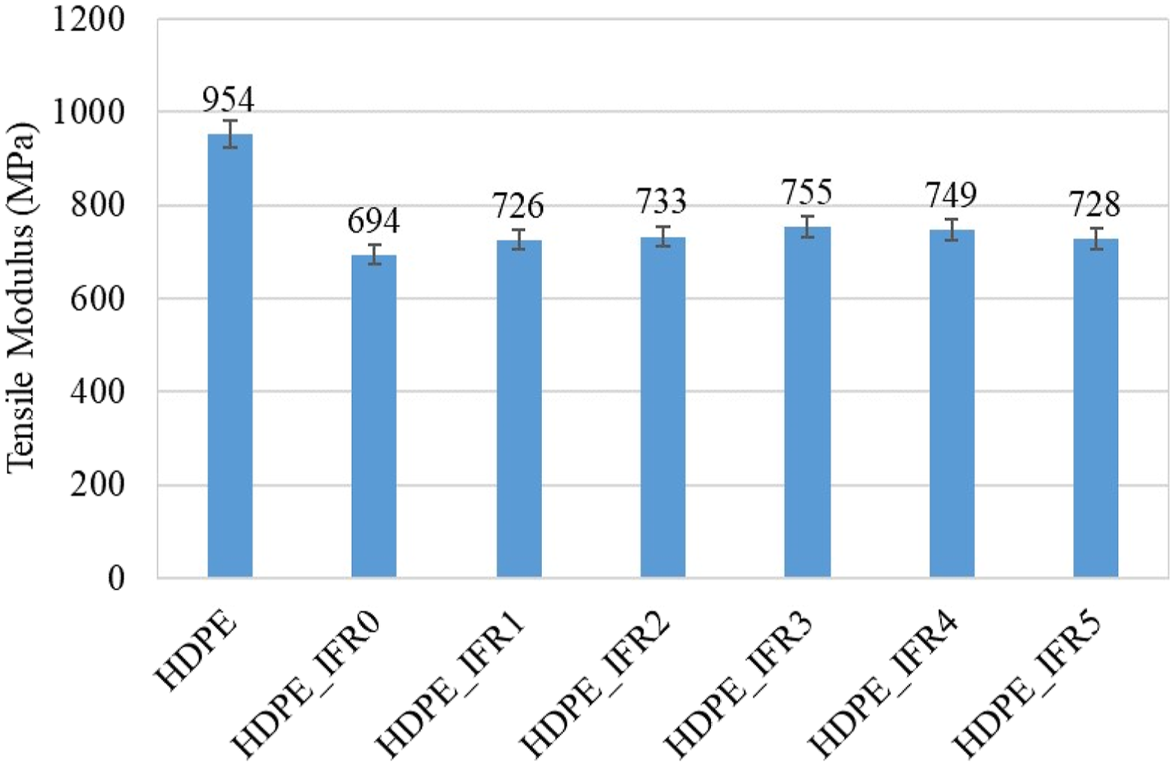
Figure 17 compares the Izod impact strength values of the notched samples. The Izod impact strength value of HDPE was found to be 7.22 kJ/m2. 25% IFR addition caused 25.6% reduction in the strength. While 1 wt %, 2 wt %, and 3 wt % FA additions resulted in slight increases in the strength with respect to HDPE_IFR0, 4 wt % and 5 wt % FA additions reduced the values. The maximum strength (5.90 kJ/m2) was obtained with 3 wt % FA addition. Izod impact strength of HDPE and its composites.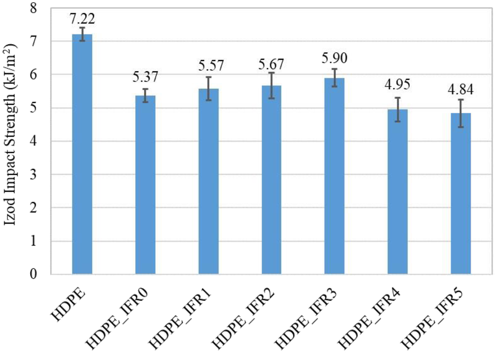
Conclusions
The effects of FA (1–5 wt %) and IFR system (25 wt %) combinations on the properties of the HDPE based composite materials were investigated in this study. The experimental results were summarized as follows. • The HDPE based composite including 25 wt % IFR (HDPE_IFR0) began to decompose at lower temperatures than HPDE due to early degradations of PER and APP. They formed a char layer which slightly increased the maximum degradation temperature by 4.2°C and decreased the rate by 19.5%. Meanwhile, the composites including FA/IFR showed similar degradation trends with HDPE_IFR0. However, FA additions further decreased the maximum degradation rate up to 30.8%. In addition, the residues at 1000°C increased with the addition of FA. The maximum residue (11.67%) was obtained with HDPE_IFR5. • IFR addition (25 wt %) increased the thermal conductivity coefficient from 0.451 W/mK to 0.462 W/mK. Moreover, it was determined that the thermal conductivity coefficients of the composites including FA increased proportionally with the amount of FA. The coefficient of HDPE_IFR5 became 12.2 % higher than that of HDPE. • Although the sample included only 25 wt % IFR could meet the requirements of UL 94 V-2 with a LOI value of 25.0 %, 1 % FA addition resulted in UL 94 V-1 with a LOI value of 26.1 %. Moreover, UL 94 V-0 rate could be satisfied by 2 wt %, 3 wt %, and 4 wt % FA additions with a LOI value of 26.6 %. However, 5 wt % FA addition caused an antagonistic effect in terms of flame retardancy. It is thought that 5 wt % FA increased the viscosity of the melt and prevented the formation and expansion of the effective char layer. • The cone calorimeter test results revealed that the peak heat release rates and the total heat release values of the composites including both IFR and IFR/FA additions were lower than those of HDPE. Furthermore, CO, CO2, and the soot production of the composites significantly reduced with respect to HDPE. NO generation increased with IFR additions due to the nitrogen content of the APP. • 25 % IFR addition caused decreases in the tensile strength, the tensile modulus, and the Izod impact strength due to partially poor compatibility of IFR in the matrix. However, FA additions slightly increased these values. It is thought that the silanated FA partially enhanced the compatibility between the additives and the HDPE matrix. Among the composites, the maximum tensile strength (22.0 MPa), tensile modulus (755 MPa), and the Izod impact strength (5.90 kJ/m2) were obtained with HDPE_IFR3.
Footnotes
Acknowledgements
The authors would like to thank “Pamukkale University Scientific Research Council” and “The Scientific and Technological Research Council of Turkey (TUBITAK)” for supporting this study under project contract no. 2021FEBE001 and 108T246, respectively. Also, the authors thank Clariant (Turkey), MKS Marmara Integrated Chemistry Industry Co. (Turkey), Tuncbilek Thermal Power Plant (Turkey), and Ultrakim Chemistry Industry Co. (Turkey) for providing free of charge the ammonium polyphosphate, the pentaerythritol, the fly ash, and 3-Aminopropyltriethoxysilane coupling agent, respectively.
Declaration of conflicting interests
The author(s) declared no potential conflicts of interest with respect to the research, authorship, and/or publication of this article.
Funding
The author(s) disclosed receipt of the following financial support for the research, authorship, and/or publication of this article: The project supported by the Pamukkale University (2021FEBE001), Türkiye Bilimsel ve Teknolojik Araştırma Kurumu (108T246).