
Abstract
In this paper, the three-dimensional progressive damage finite element models of composite bolted connection and adhesive-bolt hybrid connection were constructed, and the accuracy of the model is verified by comparing with the experimental results. The energy-based B-K criterion was used to simulate the damage and evolution of the adhesive layer, and the effects of bolt hole diameter, pre-tightening force and layup sequence on the failure characteristics of composite mechanical connections were analyzed. The results show that, in the bolted connection model, the final failure mode is typically extrusion damage near the bolt hole, with matrix failure being the primary form of failure. Appropriately increasing the diameter of the bolt hole or applying an appropriate pre-tightening force can both enhance the connection strength. Maximal strength of the connection structure is achieved when the first layer in the connection area is oriented at 0°, whereas if the first layer is oriented at 90°, the connection's bearing capacity is minimally reduced. In the adhesive-bolt hybrid connection model, the fiber and matrix damage of the four plies closest to the adhesive layer mainly spread along the 45°direction, and the damage is mainly matrix tensile damage.
Introduction
With the advantages of high specific strength, high specific stiffness, flexibility in material layup design and good fatigue resistance, carbon fiber composite materials have been widely used in aerospace with the in-depth research on composite materials. 1 In composite material applications, multiple components are joined together by some temporary or permanent bonding method. 2 At the same time, most of the failure and damage of composite material structures occur at the joints of composite materials. Therefore, it is of great importance to study the failure mechanism of composite mechanical connections.
Adhesive joints, bolted joints, and hybrid joints are widely used in the aerospace field.3,4 The adhesive joint is simple, which can effectively reduce the weight and cost of composite material components. The connection performance of the adhesive joint depends largely on the mechanical properties of the adhesive, the connection load distribution is relatively uniform, and the main failure form is the peeling of the adhesive layer, which leads to the reduction of the connection strength until the final failure.
The connection strength of the adhesive joint is relatively low, therefore, the ability to resist damage is relatively limited, and it is not easy to disassemble. The bolted connection structure has stronger bearing capacity, higher connection reliability, and can well overcome the peeling during the bonding process. However, due to the existence of bolt holes in the bolt connection, there is a phenomenon of stress concentration, and its main failure mode is extrusion failure near the bolt hole. For the adhesive-bolt hybrid connection, in the load-bearing process, the adhesive layer bears the load firstly. When the adhesive layer fails, the damage of the adhesive layer expands from the surrounding to the bolt hole, which effectively reduces the stress concentration problem near the bolt hole. When the adhesive layer is damaged, it is carried by the bolts, and the hybrid connection combines the advantages of adhesive bonding and bolts.5,6
The research on the failure characteristics of composite material connections mainly includes the following three methods: analytical method, experimental method, and finite element method. Among them, the analytical method calculates the load distribution of bolts by establishing a reasonable connection stiffness, and its form is often simple and efficient. The experimental research method has higher requirements on the performance of the equipment, and at the same time consumes a lot of time and cost. The finite element method can better predict the connection strength of composite materials and the damage evolution process of composite materials by establishing the constitutive and damage judgment criteria of composite materials, as well as the stiffness degradation rules.
In terms of composite bolted connections, Mccarthy et al.7,8 established the finite element calculation model of composite material convex head bolt connection, and discussed the influence of bolt gap on the connection structure.Wang et al. 9 prepared glass fiber (GF)/polypropylene (PP) thermoplastic composite rivets (GF/PP rivets), which improved the performance of thermoplastic composite joints and reduced the joint weight. Minnetyan et al. 10 evaluated the structural durability, damage tolerance, and progressive fracture characteristics of bolted graphite/epoxy composite laminates through computational simulations. The results show the sequence of damage progression and structural fracture resistance at different degradation stages.
Mandal et al. 11 established a three-dimensional progressive damage model of composite multi-nail connection structure, and studied the influence of bolt hole diameter and pre-tightening force on connection strength. Huang et al. 12 Studied the extrusion of composite material single-nail bolt structure, and analyzed the influence of factors such as contact surface friction, bolt stiffness and metal plate stiffness on the load-carrying performance. He et al. 13 verified the feasibility of the method for estimating the single shear connection strength of T800 type composite bolts by comparing with the experimental results. Jiang et al. 14 discussed the effects of clearance and interference fits on the joint stiffness. The results showed that clearance fit would reduce the stiffness of composite single-bolt joints, while interference fit could increase the stiffness of bolted joints. Zhou et al. 15 established the stiffness degradation model of composite resin matrix composites based on the finite element method. The finite element model was used to predict the tensile failure behavior of typical composite bolt structures, and the accuracy and feasibility of the model was verified. Hühne et al. 16 adopt the three-dimensional Hashin failure criterion, the stiffness sudden drop method and the continuous degradation method. The calculation results of the stiffness sudden drop method are relatively conservative, and the continuous degradation model is closer to the experimental results.
Innovation and technology are required to create hybrid joints of metal and polymer. Due to its lightweight and corrosion-resistant properties, it is essential to develop welding techniques to join dissimilar materials and use them in engineered structures. 17 In terms of composite hybrid connections, experiments and finite element analysis models are often used for investigation. Kelly et al. 18 carried out experiments on hybrid joints, which showed that adhesive-bolt hybrid joints have higher strength and stiffness, and better fatigue life. The effect of adhesive properties and layup sequence on the performance and failure modes of hybrid joints was investigated. Hoang et al. 19 established a finite element analysis model to discuss the distribution of stiffness and bond stress of adhesive and hybrid connections. Chowdhury et al. 20 carried out experiments on mechanical connection, adhesive bonding and hybrid connection of composite materials. The experimental results showed that there was no significant difference in the static strength of the three connection methods. Lopez-cruz et al. 21 found that the connection strength of the hybrid connection is higher than that of adhesive and bolted connections. At the same time, the influence of the thickness of the laminate and the material properties of the adhesive on the strength of the hybrid connection was studied. For the study of the load-bearing mechanism and failure sequence in composite hybrid connections, Barut et al. 22 established a semi-analytical solution for the stress analysis of single-lap joint hybrid structures. When the adhesive layer begins to wave and break, the bolt structure does not bear the load, and when the adhesive layer is degummed to a certain length, the bolt structure bears the load. Liu et al. 23 established a prediction model for the strength of the double-lap adhesive-bolt hybrid connection. The dip method was used to calculate the stiffness degradation. The numerical results showed that the failure of the adhesive layer occurs firstly, and the final failure form was the extrusion of the hole edge of the composite laminate, which indicated that hybrid joints are stronger than bolted and glued joints. Zhao et al. 24 studied the influence of the secondary bending effect on the mechanical behavior of the single lap bolt connection. The results showed that the secondary bending effect will cause the bolt to tilt and the laminated plate to warp, the local deformation caused by the secondary bending reduce the contact area, and accelerates the failure of single-lap bolted connections. Romanov et al. 25 conducted a parametric study on the single-lap double-bolt hybrid joint of composite laminates, and discussed the influence of geometric parameters on mechanical parameters such as joint strength, performance, and stiffness. Gamdanni et al. 26 carried out experiments on pure bolted joints and hybrid bolted joints, and the results showed that the fatigue life of hybrid joints was higher than that of pure bolted joints under the same conditions.
After the stress and strain distribution of the composite material is obtained, it is necessary to judge the damage mode of the composite material and simulate its stiffness reduction process. The progressive damage model (PDM) had been successfully applied to engineering calculations.27,28 Composite damage criteria are used to determine the damage modes of fibers and matrix. Among many failure criteria, the 3D Hashin criterion has a simple form and considers the stress component
Based on the above, the direct sudden drop method has been used in the existing research on stiffness degradation, however, this method cannot describe the progressive damage process of composite materials well. The virtual crack method and cohesive force model are often used in failure analysis, which need to determine the initiation position and propagation path of the crack in advance, which does not meet the requirements of damage prediction. Existing studies generally analyze the mechanical properties of mechanical joints, glued structures, and hybrid connections, however, there are few related studies on the mechanical behavior of failure of adhesive-bolt hybrid connections. In this paper, the failure characteristics of bolted connection and adhesive-bolt hybrid connection are comprehensively analyzed, and a three-dimensional progressive damage finite element model of composite material bolted connection and adhesive -bolted hybrid connection is constructed. The effects of bolt hole diameter, pre-tightening force and layup sequence on the failure behavior of composite mechanical connections are discussed in the continuous degradation mode. The damage and evolution of the adhesive layer were simulated using the energy-based B-K criterion, and the damage initiation and evolution of composite bolted joints and hybrid joints were predicted.
Analysis method of mechanical properties of composite materials
Failure criteria and stiffness degradation model of composite materials
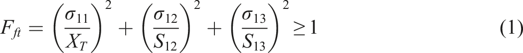
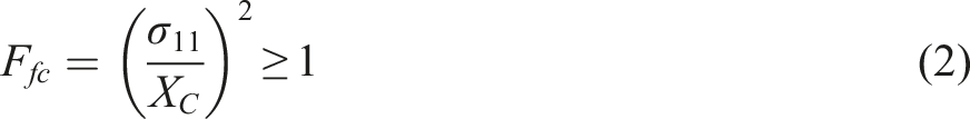
With the continuous increase of the external load of the composite material connection structure, material failure will inevitably occur. Due to the anisotropy of the material, different damage modes will appear inside the structure. In this paper, the stress-based three-dimensional Hashin failure criterion is used to predict the fiber and matrix damage of composite materials, and its expression is as follows:
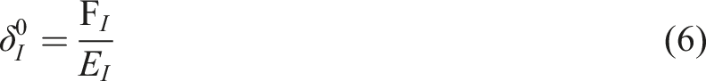
Fiber failure in tension (
Fiber failure in compression (
Matrix failure in tension

Matrix failure in compression
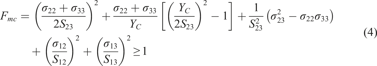
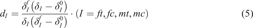
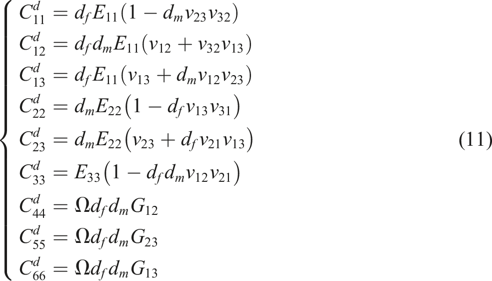
For the progressive damage of composite materials, when the composite material unit satisfies one or more of the formulas (1–4), it indicates that the composite material has begun to damage, and the composite material unit enters the corresponding damage mode. At this time, the stiffness of the composite material begins to degrade, so it is necessary to define a stiffness degradation scheme to simulate the progressive damage process of the composite material. The expression of progressive damage degradation is as follows:
36

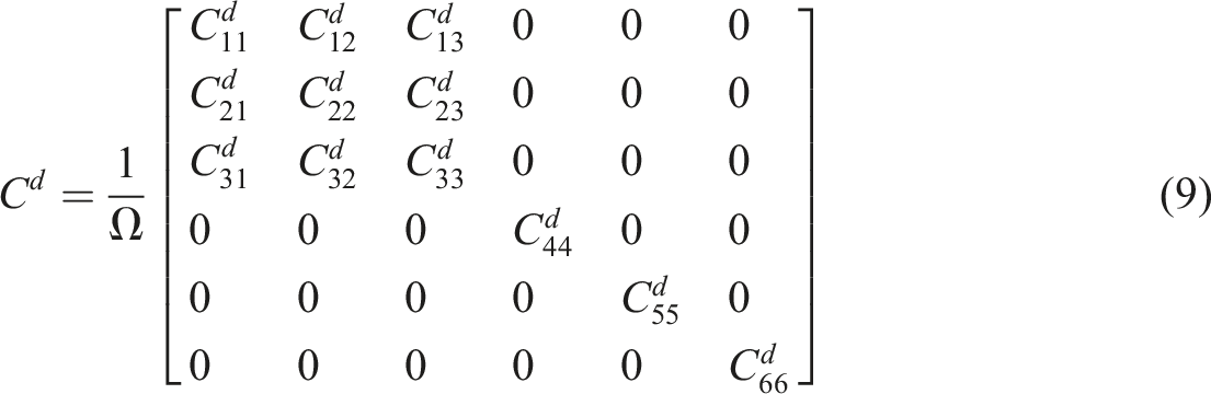
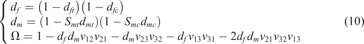
Among them,
Progressive damage model of cohesive force of adhesive layer
The Cohesive unit model based on cohesion is used to simulate the damage of the adhesive layer, and its bilinear constitutive model is shown in Figure 1. Coheisve element bilinear constitutive model.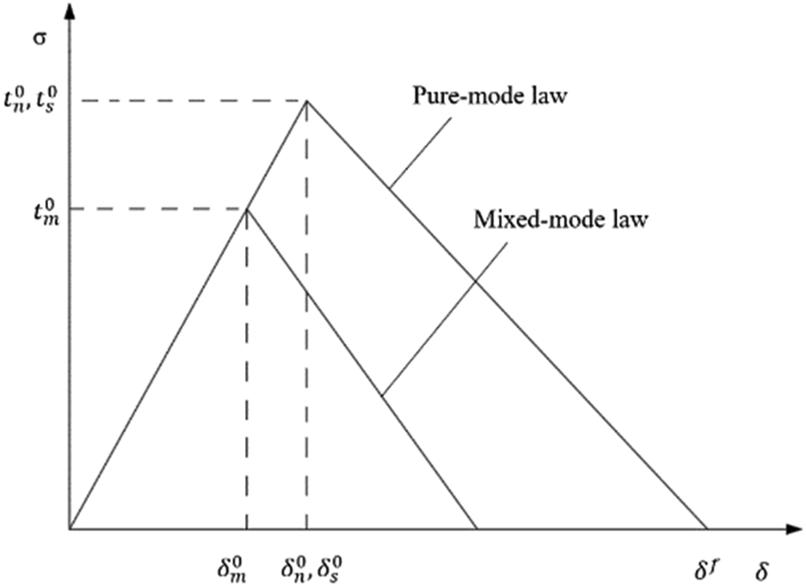
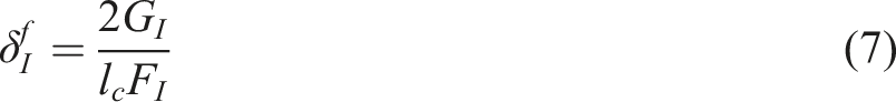
Its constitutive relation expression is as follows:
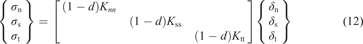


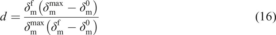

In the calculation of the progressive damage process of composite materials, the stiffness matrix of the material is calculated first, and the stress and strain of the material integration point unit are calculated according to the constitutive equation of the material. Then the updated stress tensor is brought into the Hashin criterion for failure judgment. If the element fails to meet the failure condition, continue to increase the displacement load, otherwise, reduce the stiffness, and use the strain-based damage evolution model to calculate the damage variable. If the stiffness matrix degenerates, the stresses are redistributed. Repeat the above process until the final failure of the composite material structure occurs, and the load-displacement curve of the composite material connection is obtained. The progressive damage of the adhesive layer was calculated using the cohesive force model.
Composite bolted connections
Finite element model of bolted connection
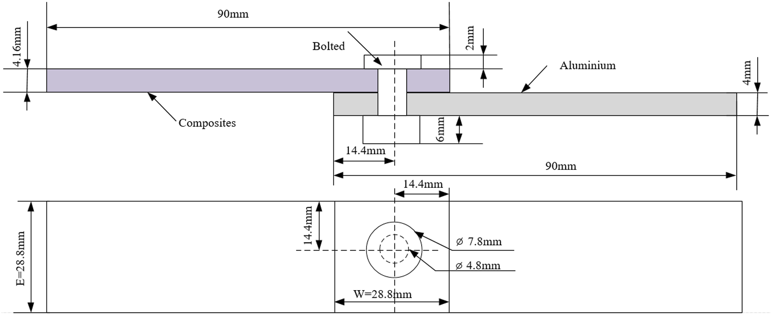
In order to verify the accuracy of the model, numerical results are compared with Riccio's experimental results
37
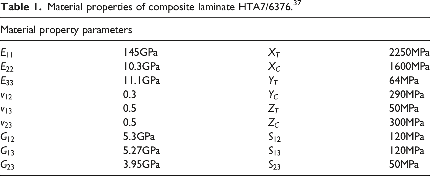
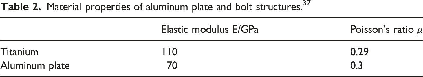
for bolted connections. The composite bolted connection model mainly includes three parts, aluminum plate, bolt and composite laminate, and its geometric model was shown in Figure 2. The material properties of composite laminate (HTA7/6376) are shown in Table 1, and the material properties of aluminum plate and bolt structures are shown in Table 2. Geometric model of bolted connection. Material properties of composite laminate HTA7/6376.
37
Material properties of aluminum plate and bolt structures.
37
The layering method is Mesh division of joint area (a: bolt mesh; (b) contact area mesh; (c) thickness direction mesh).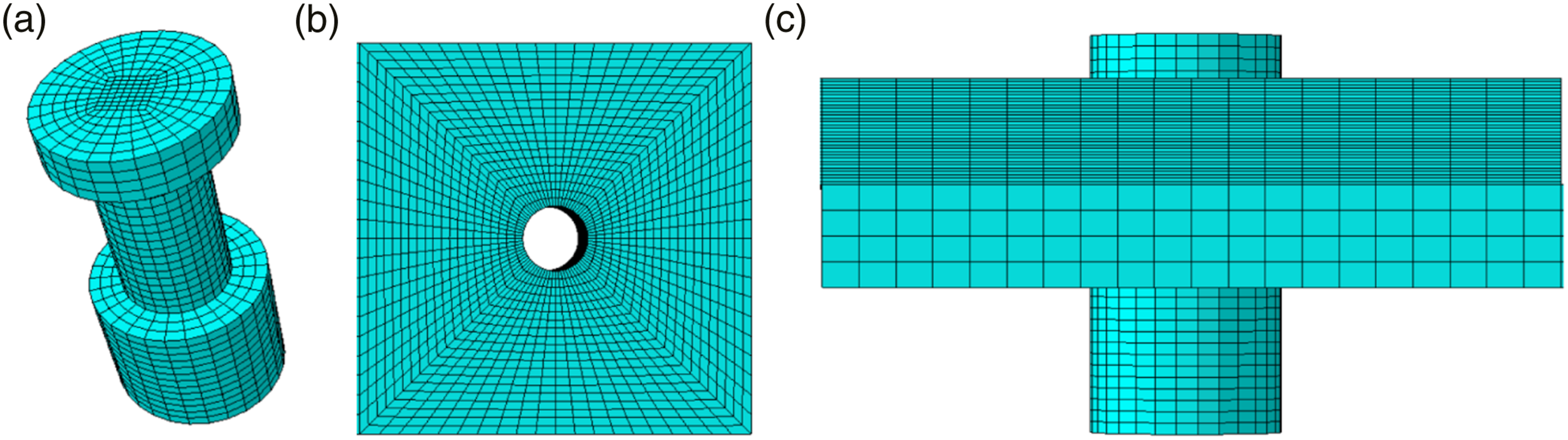
Analysis of bolted connection stress and failure characteristics
The comparison between numerical simulation and experimental results of single-lap composite bolt connection is shown in Figure 4 Comparison of displacement and load curve responses.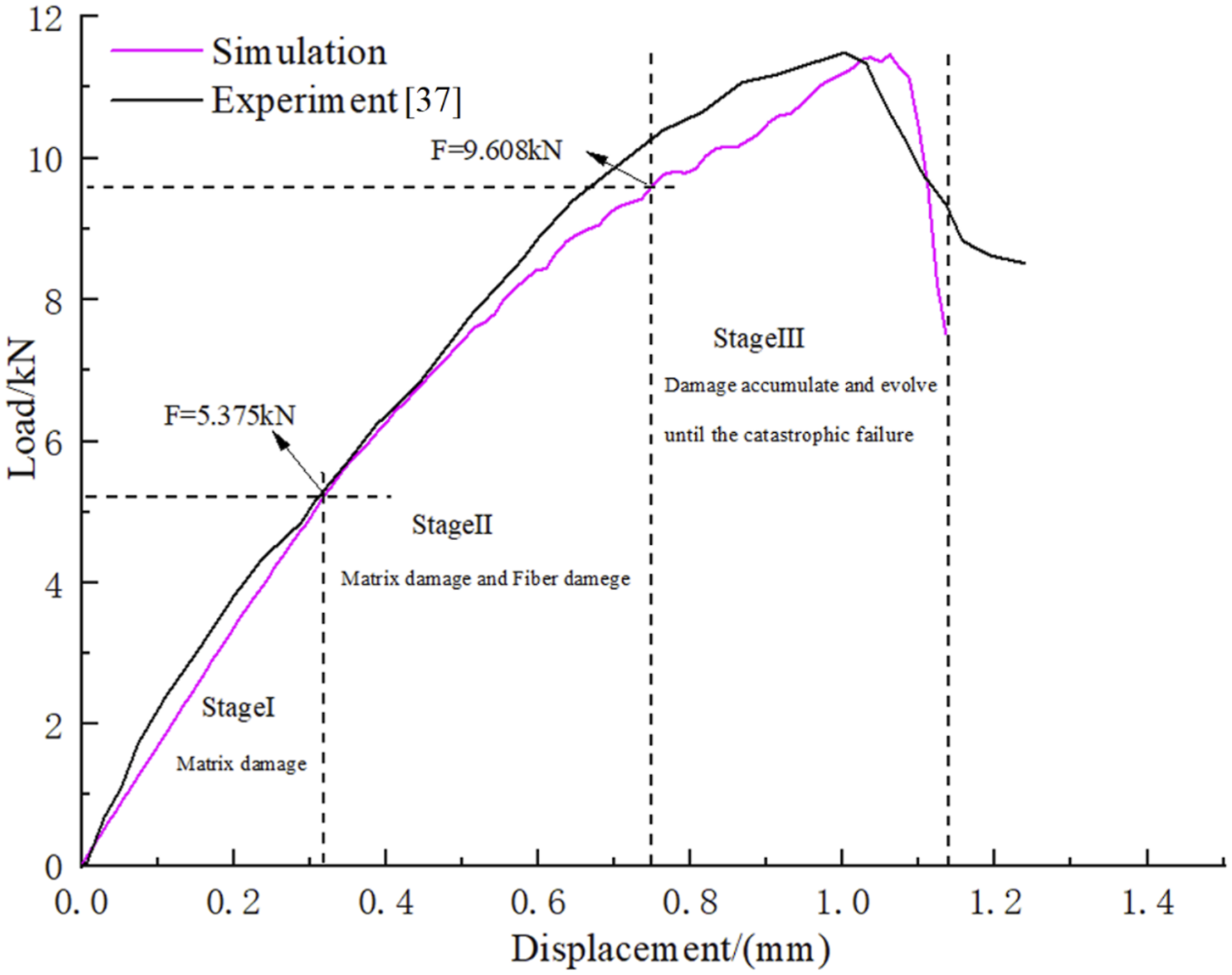
The overall failure characteristics of composite laminate structure are shown in Figure 5 Overall failure diagram of composite laminate structure.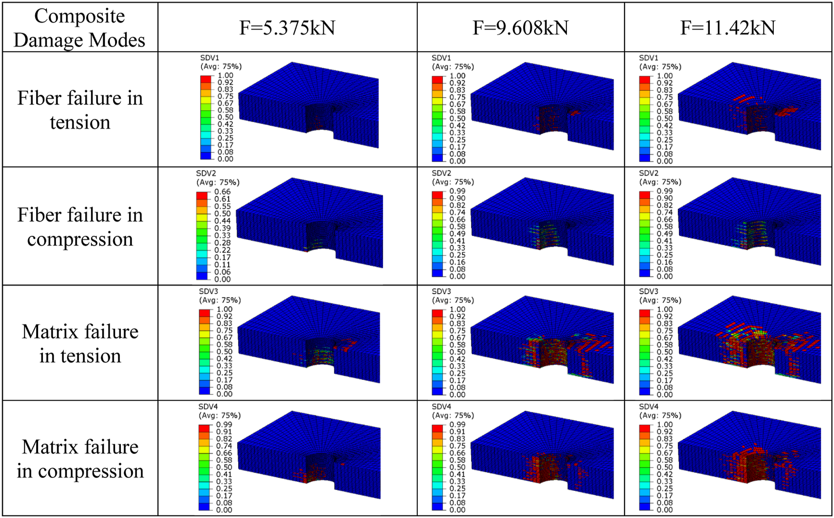
In the third stage, as the displacement load continues to increase, the damage inside the composite material continues to accumulate, and the bolts continue to squeeze the composite material, resulting in a decrease in stiffness. The composite material loses its bearing capacity, and the bolted connection model eventually fails. According to the above analysis and discussion, as the displacement load continues to increase, fiber and matrix damage begins to occur inside the composite material, and the damage continues to evolve. At this time, the bolt holes of the composite material are severely crushed, which leads to a decrease in the bearing capacity of the composite material bolt structure. The final failure mode of composite bolted connection is the extrusion failure near the composite material hole. The composite material’s failure mode is mainly reflected in the damage of the matrix and fibers. At the same time, the damage of the matrix is greater than the fiber. When composite bolted connections fail, extensive matrix damage occurs inside the composite laminate.
Influencing factors of bolted connection
There are different types of bolt specifications in the project, and different bolt hole diameters will cause different damage to the continuity of the fibers, and have a certain impact on the strength of the bolt connection. Therefore, it is necessary to analyze the influence of different bolt hole diameters on the strength of composite bolted connections. In this paper, three types of bolts, M4.8, M6, and M8, are comprehensively analyzed, and their load-displacement curves are shown in Figure 6. It can be seen that as the bolt hole diameter increases, the contact area between the screw and the inner wall of the composite bolt hole increases, and the bearing capacity of the composite bolt connection also increases. However, with the increase of the bolt hole diameter, when the inflection point appears in the load-displacement curve, its limit displacement gradually decreases. Therefore, when designing a composite material bolted connection structure, within a certain range, selecting a larger bolt diameter can withstand a larger external load, and selecting a smaller bolt diameter can withstand a larger limit displacement. Effect of bolt diameter on connection strength.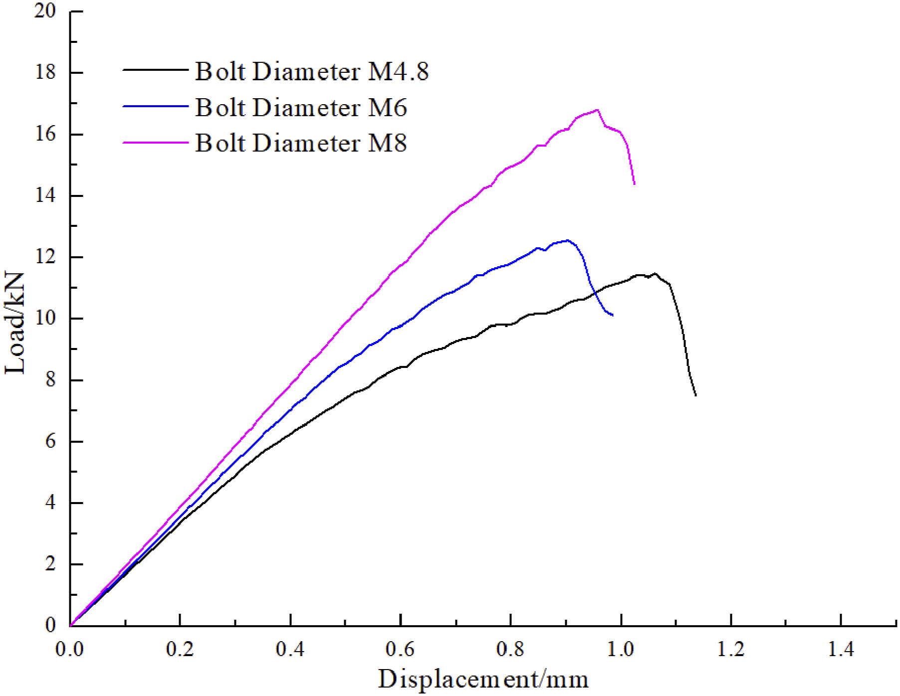
Commonly used ply angles in engineering are 0°, ±45°, 90°. Among them, the 0° layup bears the transverse tensile force, the ±45° layup mainly bears the extrusion and impact load of the material, and the 90° layup mainly bears the longitudinal shear force. Therefore, different layup sequences have certain influence on the overall performance of the composite material. This paper mainly studies the effects of four lay-up methods on the bolted connection strength, Layer method 1 Effect of layup sequence on bolted connection strength.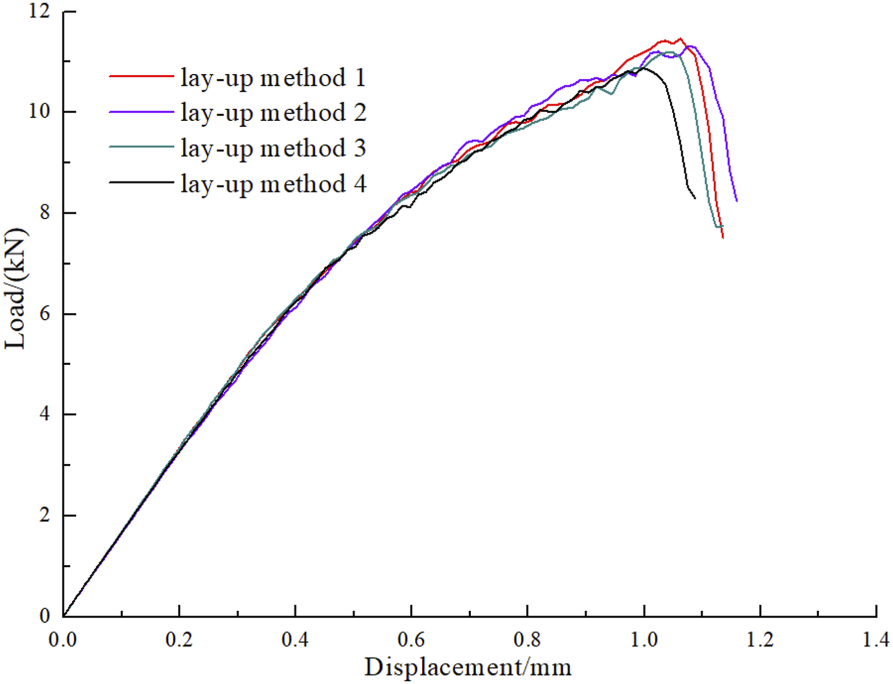
According to the mechanical design manual, the calculation formula of the bolt Pre-tightening force is as follows:
In order to study the effect of pre-tightening force on the strength of composite bolted connection, three pre-tightening forces of 2kN,7.5kN, and 10kN were selected in this paper, and the strength of the bolted connection structure is shown in Figure 8. When the pre-tightening force is 2kN, the strength of the bolted connection structure increases. When the pre-tightening force is 7.5kN, the pre-tightening force has a small increase in the connection strength. When the bolt pre-tightening force is 10kN, the connection strength is reduced, because the excessive pre-tightening force will cause damage to the composite material near the bolt hole, which will lead to a decrease in the strength of the composite material bolted connection. Therefore, proper pre-tightening force can increase the strength of composite bolted connection, while excessive pre-tightening force will lead to a decrease in connection strength. Effect of pre-tightening force on bolted connection strength.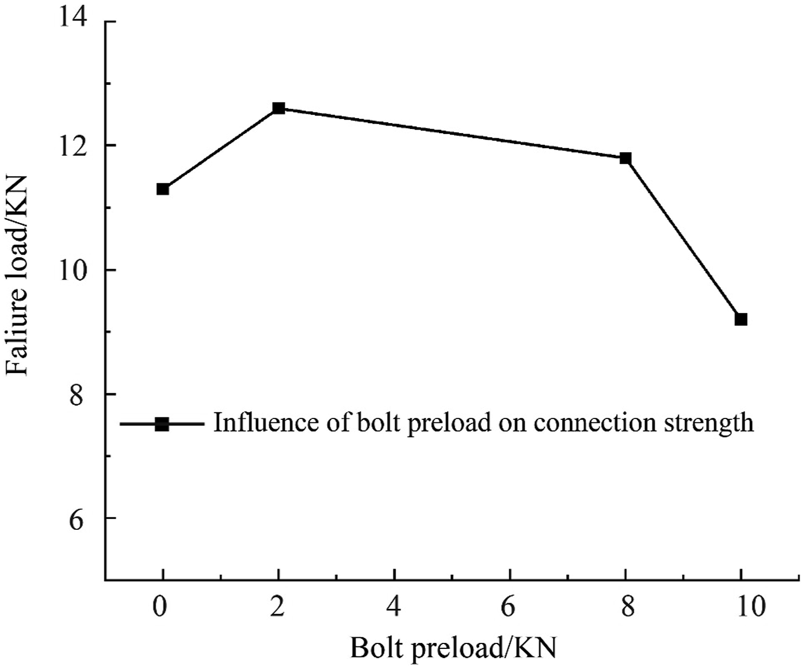
In order to study the effect of the width-diameter ratio and end-diameter ratio of composite materials on the bolt connection strength, this paper studies the four end-diameter ratios of E/d=4, E/d=5, E/d=6, E/d=7 on the bolts. The influence of connection strength, as can be seen from Figure 11, with the increase of the end-diameter ratio, the connection strength of the bolt increases. When the end-diameter ratio is in the range of 6-7, the strength of the bolt connection does not increase significantly, but the failure Movement has been increased. It can be seen from the load-displacement curve that the stiffness of the bolted connection is the smallest when E/d=4, and the stiffness of the other three bolted connections shows a high consistency, as shown in Figure 9. Influence of end-to-diameter ratio on bolt connection strength.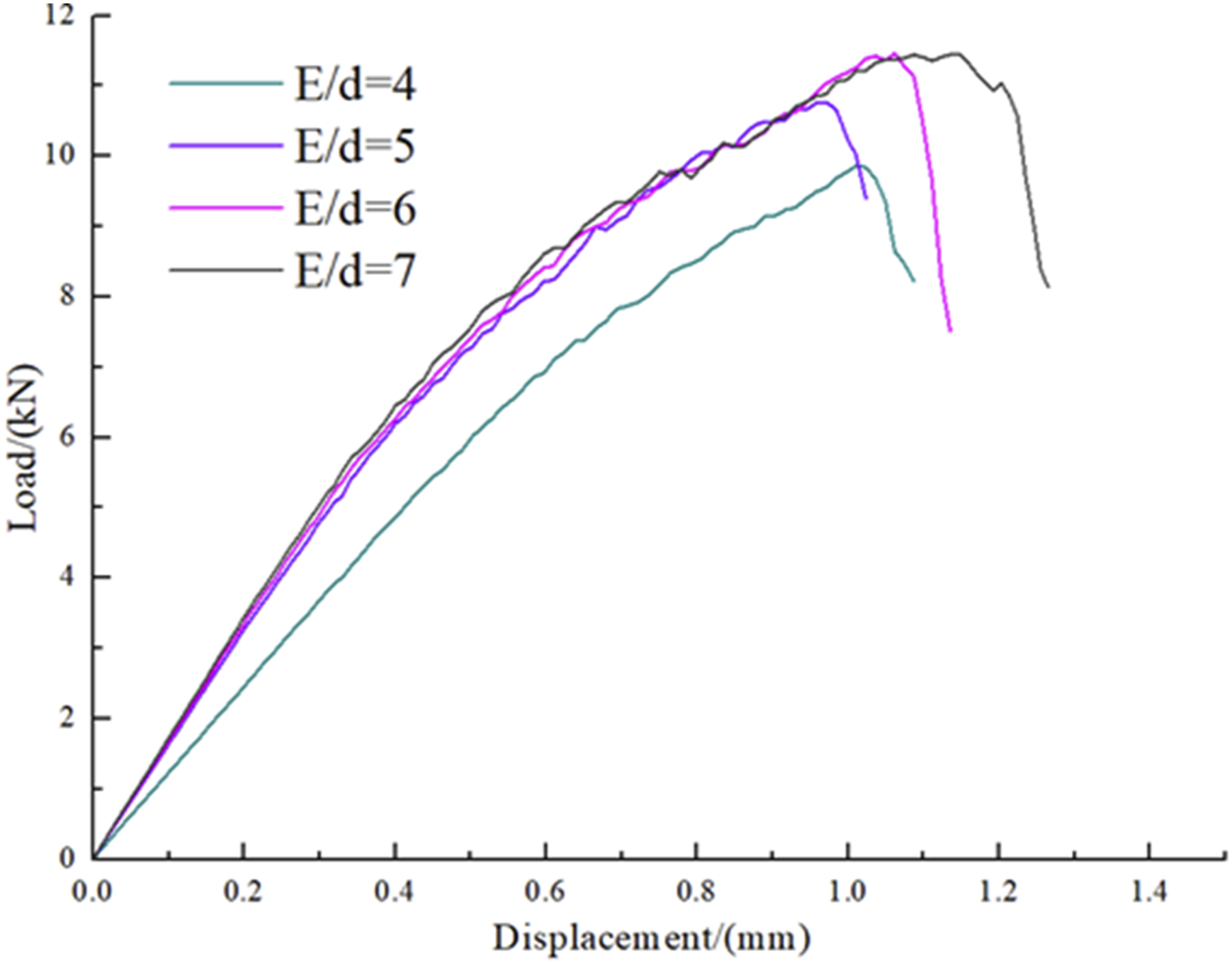
In this paper, the effects of three width-to-diameter ratios w/d=4, w/d=5, and w/d=6 on the bolt connection strength are selected, and the displacement load curve is shown in Figure 10. It can be found that when w/d=4, the connection strength and failure displacement are the lowest. Among them, when w/d=6, the bolt connection strength is the highest. When w/d is in the interval,4,5 the bolt connection strength does not increase significantly, and the failure displacement increases slightly. Effect of width-diameter ratio on bolt connection strength.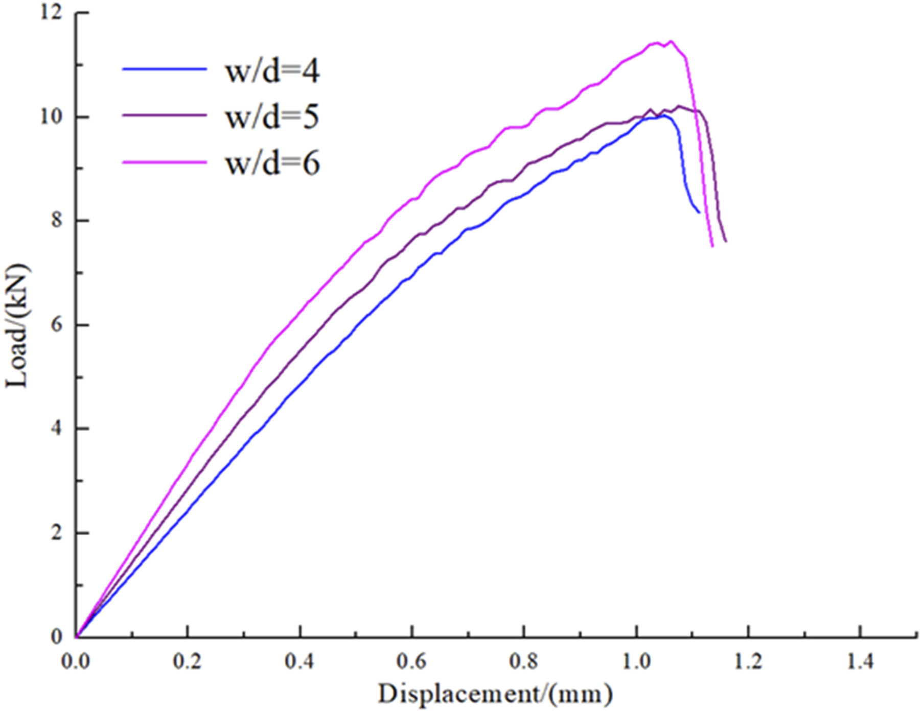
Failure characteristics of composite adhesive-bolt joints
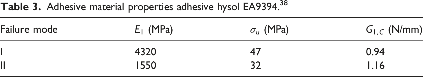
Adhesive material properties adhesive hysol EA9394. 38
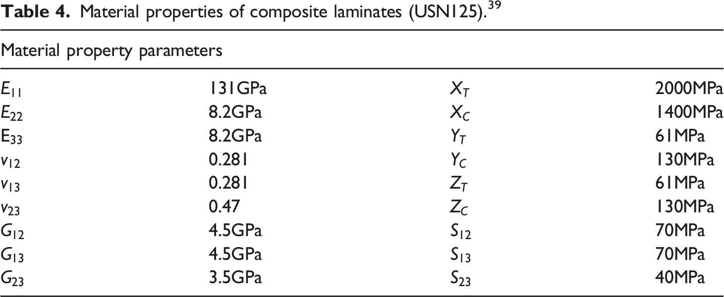
Material properties of composite laminates (USN125). 39
Verification of the finite element model of composite adhesive-bolt hybrid connection
The geometric dimensions of composite bonded-bolted hybrid connections
39
are shown in Figure 11. The model consists of four parts: composite laminates, bolts, aluminum plates, and adhesive layers. The sequence of composite layers is Geometry model of hybrid connection.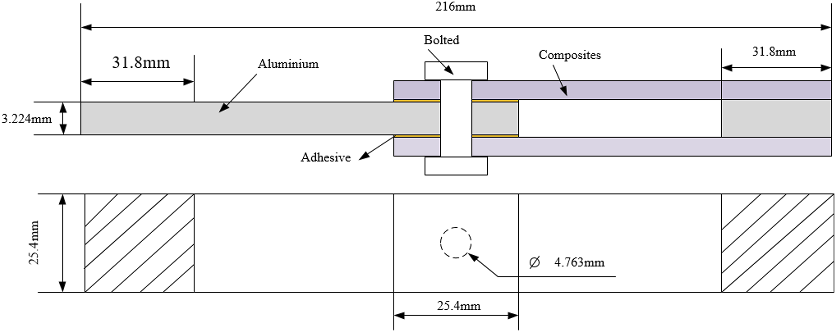
Under the longitudinal tensile load, the mechanical properties of different materials present relatively complex mechanical behavior, and there are contact nonlinearities between bolts and laminates, laminates and adhesive layers, bolts and holes. As the displacement load increases, the stiffness gradually degrades, and the composite material and adhesive layer gradually fail. In the mixed connection finite element model, the grid type of composite laminates, aluminum plates and bolts adopts 8-node reduced integration element (C3D8R), and the adhesive layer element adopts 8-node three-dimensional viscous element (COH3D8), and the number of meshes is 164,160. Composite single plies and adhesive layers correspond to one layer of mesh in the thickness direction. In order to ensure that the contact area of the composite material and the glue line are at the same node, the laminate and the glue line are modeled integrally. The mesh is densified in the connection area between the bolt hole and the adhesive layer, and the gradual mesh transition is adopted near the bolt hole and the connection area, as shown in Figure 12. Mesh division of joint area (a: Progressive mesh division near bolt holes; (b) Bolt mesh division; (c) Details of glued-bolt hybrid connection).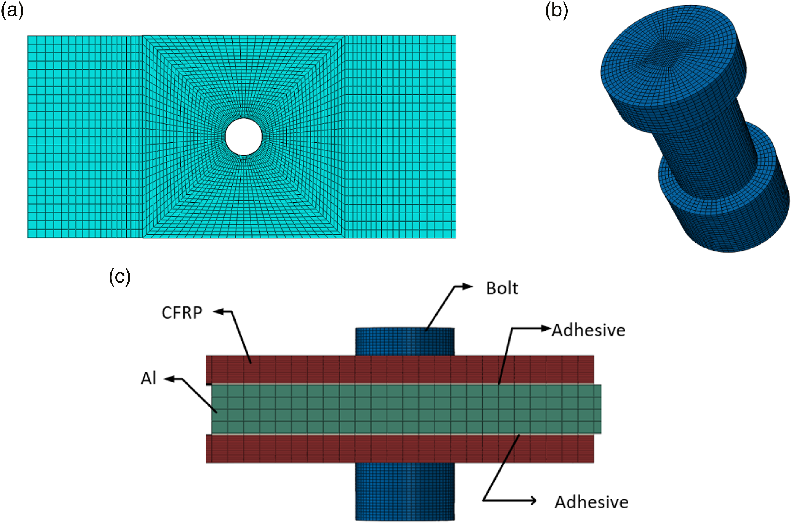
The right end of the Al plate adopts the fixed support boundary condition, and the displacement load along the X direction is applied to the left end of the composite laminate. The finite element model of the hybrid connection includes the contact between the bolt and the laminate, and the contact between the screw and the hole. The contact is realized by defining the friction of each contact surface, where normal is defined as hard contact and tangential is defined with a coefficient of friction of 0.3. The integrated modeling of the composite material and the adhesive layer does not involve the contact mechanical behavior between the adhesive layer and the plate, but the model also includes the contact between bolt head and the upper and lower composite laminates, the contact between the screw rod and the bolt hole. The contact type is surface-surface contact and the slip type is finite slip.
Figure 13 Failure load-displacement curve of adhesive-bolt hybrid connection.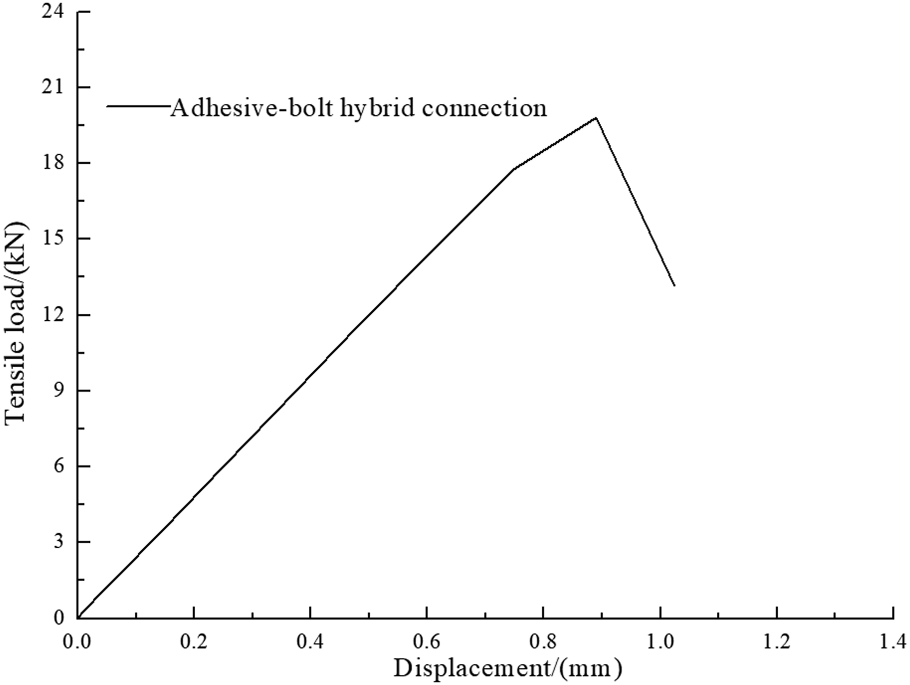
Damage evolution of composite laminates and adhesive layers
The damage evolution of the adhesive layer is shown in Figure 14 The damage and evolution of the adhesive layer.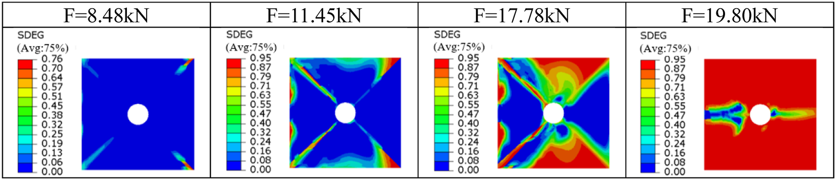
The damage and evolution process of composite laminates are shown in Figure 15. When the tensile load is less than 5.88kN, there is no fiber or matrix damage in the composite laminates. With the increase of displacement load, when the load reaches 8.48kN, a small amount of damage begins to appear around the adhesive layer. When the displacement load curve is at 5.88kN-17.78kN, a small amount of fiber damage occurs inside the laminate, and a certain amount of matrix damage occurs near the bolt holes of the laminate. At this stage, the screw begins to squeeze the composite material, causing damage to the composite material, the adhesive layer and the bolt structure are jointly stressed. When the tensile load is 19.8kN, the adhesive layer has completely failed. With the increase of the displacement load, the damage inside the laminate continues to accumulate, the stiffness degrades, and the stress is redistributed. At this time, the fiber is mainly stretched, and the damage distributed near the bolt holes, the compression damage mainly occurs in the small area at the upper end of the bolt holes. The tensile damage of the matrix is more than the compressive damage of the matrix, and it is also distributed near the bolt holes. As the displacement load increases, the screw continuously squeezes the inner wall of the composite bolt hole. When the damage accumulates to a certain extent, the displacement load curve appears an inflection point, and the bonded-bolt hybrid connection rapidly loses its bearing capacity, and the overall structure fails. Composite laminate damage and its evolution.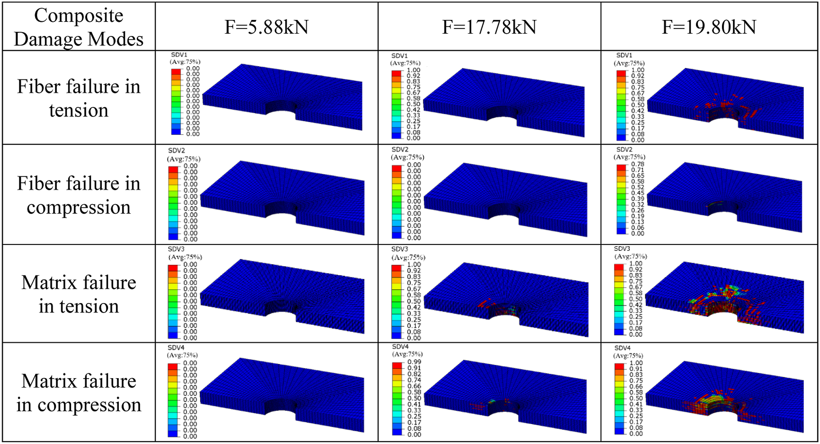
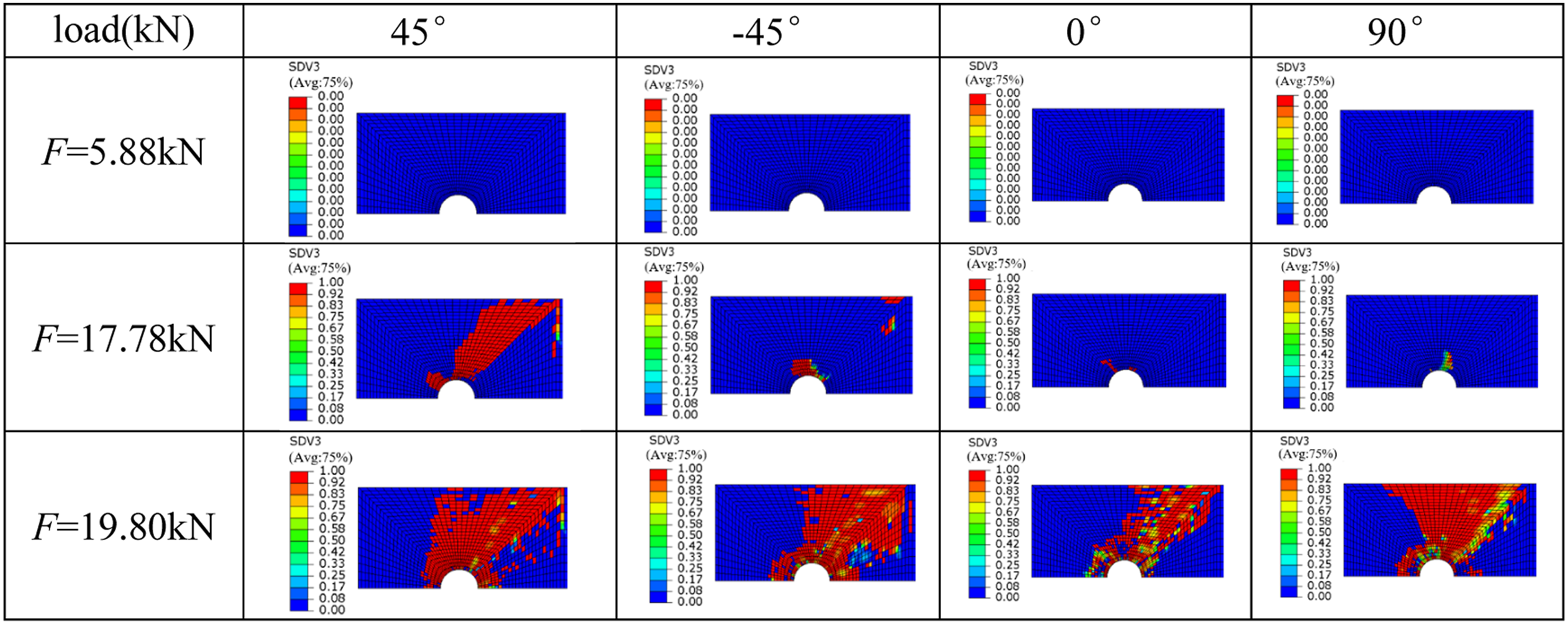
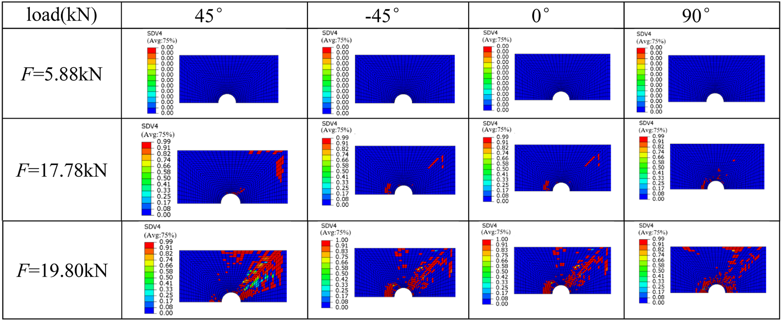
The bonded area between the adhesive layer and the composite material may also lead to failure of the composite material due to damage to the adhesive layer. Therefore, this paper analyzes the four layups closest to the connection between the composite material and the adhesive layer. Laminate layers closest to the glue line are 45°, −45°, 0°, 90°. The fiber tensile damage is mainly distributed near the bolt holes, and expands along the 45° direction at the same time, and the fiber damage of the 45° ply and 0° ply is more serious, as shown in Figures 16 Tensile damage of the first four laminated fibers in the joint area. Tensile damage of the first four plies in the joint area. Compression damage of the first four plies in the joint area.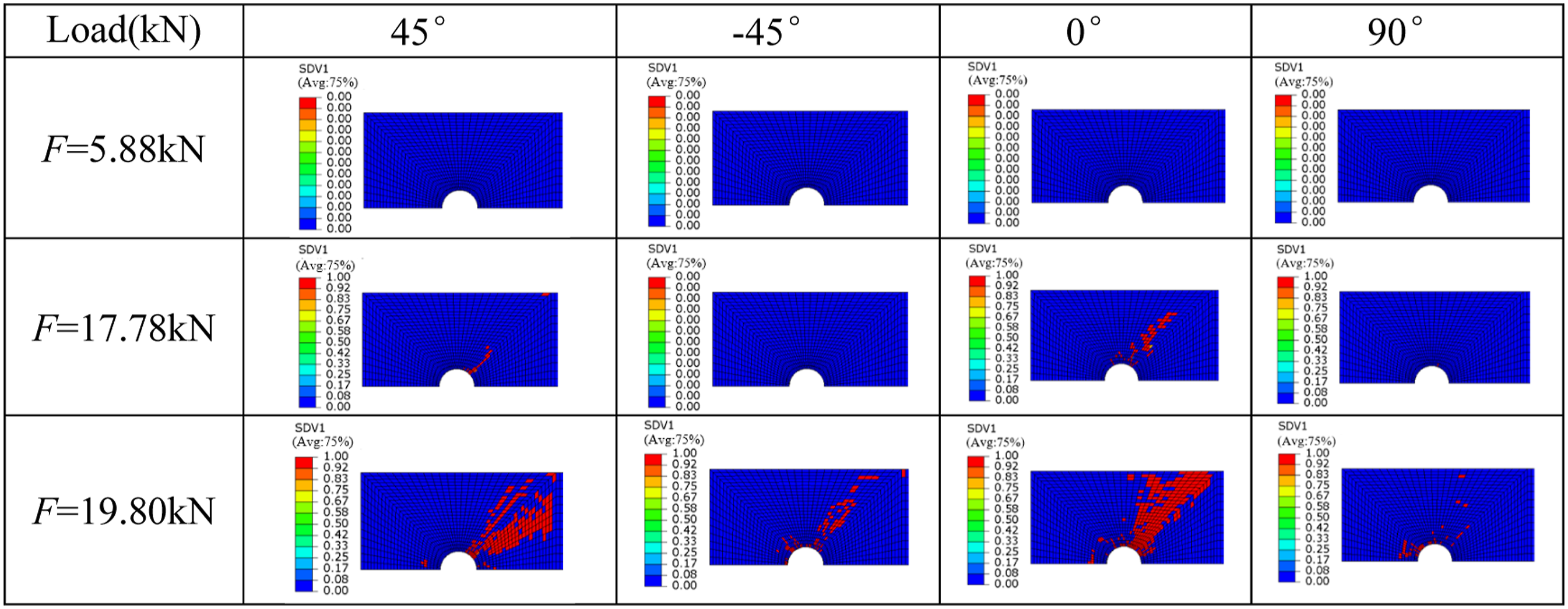
Conclusions
In this paper, the models of composite bolted connection and adhesive-bolt hybrid connection are established. The correctness of the model is verified by comparison with the experiment, and the bolted connection and hybrid connection between the composite material and the aluminum plate can be well predicted. The parameters affecting the bolted connection strength were analyzed, and the load-bearing mechanism and damage evolution law of the connected parts were revealed. The conclusions are as follows: (1) In the bolted connection model, an increase in displacement leads to internal fiber and matrix damage within the composite material, and the load-displacement curve shows nonlinear behavior. The final failure mode is typically extrusion damage near the bolt hole, with matrix failure being the primary form of failure. (2) Appropriately increasing the diameter of the bolt hole or applying an appropriate pre-tightening force can both enhance the connection strength. However, it should be noted that excessive pre-tightening force may lead to the initial damage of the composite material, ultimately resulting in a reduction of the connection strength. (3) The strength of the connection structure is maximized when the first layer in the connection area is aligned at 0°. Conversely, if the first layer is oriented at 90°, the connection's bearing capacity is reduced to its lowest level. The connection strength of the 45° ply falls between the strengths achieved at the 0° and 90° orientations. (4) The adhesive layer fails first in the adhesive-bolt hybrid connection model, followed by joint load-bearing with the mechanical structure until complete adhesive layer failure. As the screw continuously squeezes the composite material's bolt hole, internal damage accumulates and suddenly decreases the connection's bearing capacity, leading to adhesive-bolt structure failure. (5) In the adhesive-bolt hybrid connection model, the fiber and matrix damage of the four plies closest to the glue line mainly spread along the 45° direction, and the damage is mainly matrix tensile damage. When the load reaches the ultimate strength of the hybrid connection, the fiber and matrix damage of the four composite monolayers propagates to the outside of the plate.
Footnotes
Declaration of competing interest
The authors declare that they have no known competing finanical interests or personal relationships that could have appeared to influence the worked reported in this paper.
Funding
This work has been supported by the Natural Science Foundation of Chongqing (Grant No. CSTB2023NSCQ-MSX0802), the Science and Technology Research Program of Chongqing Municipal Education Commission (Grant No. KJQN20210117, KJQN202201105, KJQN202201113).