
Abstract
The main purpose of this study was to observe the degree of the improvement on the film adhesive joining performance of Poly(phenylene sulfide)/Carbon Fiber (PPS/CF) thermoplastic composite laminates when their surfaces were treated by atmospheric plasma technique. For this purpose, plasma treated surfaces were compared with untreated and the traditional grit-blasted surfaces. Treated surfaces were characterized by various techniques including contact angle, surface energy, surface roughness, Fourier transform infrared spectroscopy (FTIR) and X-ray photoelectron spectroscopy (XPS) analyses. Then, joining performance of the PPS/CF composite samples bonded by an epoxy-based film adhesive was determined by using three different mechanical tests; single-lap shear strength, mode-I interlaminar fracture toughness energy, and drop-weight impact toughness. Grit-blasting surface treatment increased surface roughness of the specimens enormously (7 times more), leading to mechanical interlocking as the dominant bonding mechanism. Contrarily, plasma surface treatment resulted in formation of chemically reactive sites, thus dominant bonding mechanisms in the film adhesive joining were certain polar interactions and chemical bonding. Mechanical tests pointed out that compared to grit-blasting, plasma surface treatment resulted in considerably higher joint performance regarding interlaminar shear strength (35% more), interlaminar fracture toughness (67% more) and impact toughness (28% more), with the cohesive failure mode. Accordingly, it could be stated that traditional grit-blasting could be replaced with plasma surface treatment applied before film adhesive joining of PPS/CF composite parts in aircraft industry.
Keywords
Introduction
Film adhesives are generally partially cured thermosetting films laid in between the composite parts to be joined. Depending on the required joining performance one or more film adhesive layers could be used. In order to supply required heat energy and pressure for curing reaction properly, joining of the parts are generally accomplished in an autoclave system.
It is stated that1–3 in aerospace industry, there are several advantages of using film adhesive joining technique compared to mechanical fastening, co-consolidation, and welding methods, such as; continuous bonding along the assemble, reduced stress concentration sites, decrease in the weight of the component, more uniform load distribution in the joint, and reduced labor.
During film adhesive joining process, one or more well-known bonding mechanisms could operate. 4 For instance, “mechanical bonding” might take place due to the certain degree of surface roughness leading to “interlocking” action at the interface. “Secondary bonding” might occur due to the “polar interactions” between the surfaces. Of course, “chemical bonding” is the most significant mechanism due to the formation of “primary covalent bonds” at the interface.
In the aircraft industry, depending on the type of composite structures to be joined, different film adhesive materials are used. For instance, silicon-based film adhesives are preferred for sealing applications such as window parts or door edges; acrylic-based film adhesives for interior bins and lavatories; and polyurethane-based film adhesives especially for the aircraft parts subjected to temperature variations. On the other hand, the most commonly used film adhesive materials are epoxy-based ones due to their higher chemical resistance, higher mechanical performance and low shrinkage.5,6 Therefore, epoxy film adhesives are used to obtain durable joints in many structural critical parts of aircrafts, including wings and fuselage parts.7,8
It is known that since surface energies of the thermoplastic matrix composites are very low, 9 surface characteristics of these parts to be joined play a very significant role in the effectiveness of film adhesive joining method. 10 For instance, a degree of surface roughness might improve mechanical interlocking mechanism, while increased surface energies facilitate chemical bonding mechanism enormously. Therefore, in order to achieve proper film adhesive joining process, surfaces of these composite parts should be activated by using a kind of surface treatment technique.
For the thermoplastic matrix composite parts, available methods used in the aircraft industry can be categorized into two groups; traditional mechanical treatments such as “grit-blasting”, and chemical energetic treatments such as “plasma treatment”. In this study, effects of grit-blasting were compared with the results of plasma treatment.
Grit-blasting is a mechanical process where the material surface is exposed to abrasive particles hitting the surface with high pressure. The impact of these particles causes surface textures leading to increase in roughness together with the removal of surface contamination.11–13 Depending on the size and geometry of the composite parts to be joined, grit-blasting could be applied manually or in an automated system.
Grit-blasting leads to certain degree of cavities, i.e. surface roughness, to increase mechanical interlocking mechanism; while removal of surface contaminants might activate the functional groups if present in the matrix polymer leading to improved chemical bonding mechanism.
14
On the other hand, improper use of grit-blasting might lead to certain problems, such as; • Due to the accelerated particles, reinforcement fibers on the composite surface can be damaged. • Treatment of large and complex shaped composite components could be very time-consuming. • Since very high amount of particles are wasted, it would be very costly. • Due to the very large amounts of dust generation, it would lead significant health issues for the workers, including the environmental problems.
Plasma surface treatments are used for many polymer surfaces due to leading significant degree of surface activation required in many joining processes including film adhesive bonding. 15 Unlike the “low-pressure plasma” alternative under vacuum, atmospheric-pressure plasma systems, simply named as “atmospheric plasma”, provide in-line process capabilities, low prices, and minimal environmental and human safety requirements.16,17
In the atmospheric plasma systems, the inlet gas (oxygen, nitrogen, or air) is converted from gaseous state into plasma state upon exposure to very high voltage, then the jet is applied to the surfaces. Main parameters during application of plasma jet onto the composite surfaces are the velocity of plasma jet and the distance between the nozzle and the surface.
For the thermoplastic matrix composites, since their surface energies are very low, plasma treatment reveals functional groups for the higher efficiency of chemical bonding mechanism required for high performance film adhesive joining.
In the literature, it was observed that majority of the studies on the use of plasma surface treatment to improve joining performance of adhesive bonded composite structures were especially conducted for the traditional “thermoset matrix” composites.15,18–31 It was revealed that studies for the “thermoplastic matrix” composite structures were still very limited;32–39 some of them32–34 were conducted only for PP and PEEK matrices not for the PPS matrix; while some of them35,36 were conducted for joining of glass fiber (GF) reinforced PPS matrix composites onto aluminum or titanium metallic surfaces.
Thus, literature survey revealed that only three studies37–39 were related to the effects of plasma surface treatment on the joining performance of adhesive bonded PPS/CF composite structures, as summarized below.
The first study by Blackman et al. 37 was conducted for the “unidirectional” carbon fiber reinforced PPS matrix composites joined by epoxy based “paste” and “film” adhesive forms. They indicated that, after applying oxygen plasma to the surfaces, due to the increase in the concentration of oxygen-containing polar groups, joining performance of the paste and film adhesive bonded specimens increased significantly. In terms of G IC interlaminar fracture toughness energy, the increase was from 0.18 up to 1.45 kJ/m2.
In the study of Iqbal et al., 38 effects of plasma treatment on joining performance were compared for the glass fiber (GF) and carbon fiber (CF) reinforced PPS matrix composites bonded with epoxy-based paste adhesive. They indicated that due to the formation of functional groups and increased surface roughness after plasma treatment, joint performance of both PPS matrix samples improved. For instance, the increase in the single-lap shear strength values for the PPS/GF specimens was from 6 to 17 MPa, while for the PPS/CF specimens it was from 5 to 21 MPa.
In the recent study of Scarcelli et al., 39 PPS/CF composite surfaces were treated not only by plasma but also by ultraviolet radiation (UV) lamps for comparative purposes. Effects of these treatments on the joining performance of the PPS/CF samples were compered via epoxy-based film adhesive. They pointed out that, due to higher increases in the surface free energies of the samples after plasma treatment compared to UV treatment, increase in the joint performance in terms of single-lap shear strength was from 3 MPa up to 24 MPa for the plasma treated ones, but it was up to 21 MPa for the UV treated samples.
As discussed above, literature review revealed that there were only three published works37–39 investigating the effects of plasma surface treatment on the joining performance of PPS/CF composite parts bonded by film adhesive. Therefore, the main purpose of this study was to contribute this topic by conducting further experimental works with additional plasma treatment parameters, testing and analyses.
For this purpose, after production of the PPS/CF composite laminates, their surfaces were plasma treated by changing two different parameters (plasma velocity and plasma distance). Treated surfaces were characterized by various techniques including contact angle, surface energy, surface roughness, Fourier transform infrared spectroscopy (FTIR) and X-ray photoelectron spectroscopy (XPS) analyses. Then, joining performance of the PPS/CF composite samples bonded by an epoxy-based film adhesive was determined by using three different mechanical tests; single-lap shear strength, mode-I interlaminar fracture toughness energy, and as the first time in the literature drop-weight impact toughness. Apart from “plasma” treated samples, all procedures were repeated also for the “untreated” and the conventional “grit-blasted” PPS/CF sample surfaces, for comparison.
Experimental work
As explained in the following sections and illustrated in Figure 1, experimental work conducted in this study was basically composed of five main stages; (i) production of PPS/CF thermoplastic composite laminates, (ii) grit-blasting and plasma treatment of laminate surfaces, (iii) characterization of treated surfaces, (iv) joining of the samples by film adhesive bonding, and (v) mechanical testing to determine performance of the PPS/CF joints. Five main stages performed during experimental work.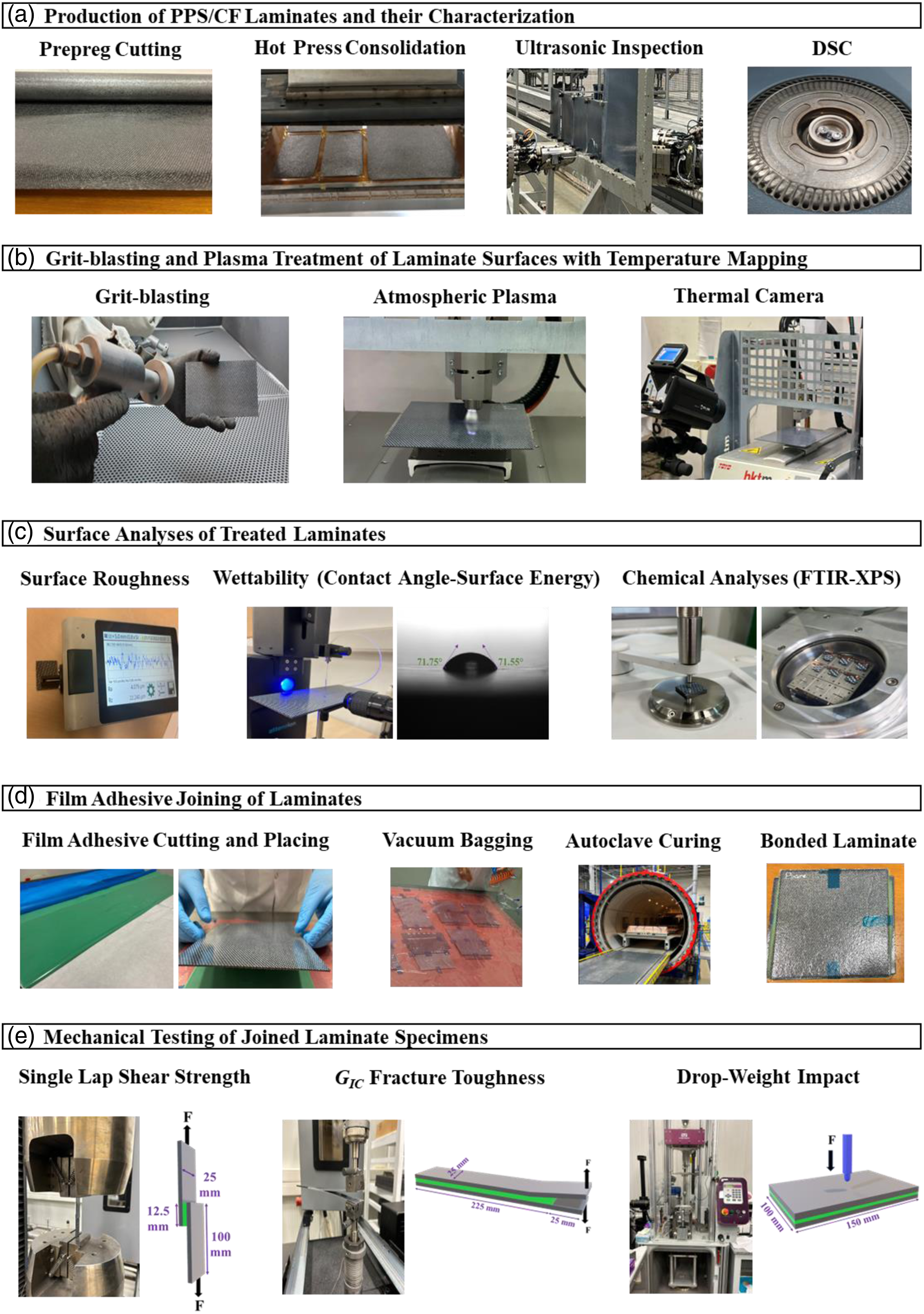
Production of poly(phenylene sulfide)/carbon fiber composite laminates to be surface treated and then joined
Production of the PPS/CF thermoplastic composite laminates to be surface treated and then joined were achieved in three steps; (i) prepreg cutting, (ii) stacking and hot press consolidation of the prepregs, (iii) ultrasonic inspection and DSC analysis of the laminate samples. Details of these sub-steps were given below.
Cutting of poly(phenylene sulfide)/carbon fiber prepregs
The commercial prepreg (Toray-Tencate Cetex TC1100) used in this study has polyphenylene sulfide (PPS) partially crystalline engineering thermoplastic matrix reinforced with continuous woven carbon fibers (CF) in 5-harness satin weave style. As reported by the supplier, PPS matrix has glass transition temperature (T g ), melting temperature (T m ), and processing temperature (T p ) range of 90°C, 280°C, and 300–330°C, respectively. It was also stated that prepregs have 43 wt% resin content, 281 g/m2 areal weight, and 0.31 mm ply thickness. These prepreg layers were cut from their roll by using an automated ply cutter Figure 1(a).
Consolidation of poly(phenylene sulfide)/carbon fiber prepregs by hot pressing
Laminates of PPS/CF were produced by stacking and consolidation of the cut prepreg layers via hot press compression molding method. In order to obtain 1.5 mm thick laminates, five plies were stacked on a hot plate surface covered by polyimide (Kapton) release film. Consolidation of the layers were achieved under a hot-pressing system (Langzauner Perfect) (Figure 1(a)), by applying three main processing parameters (Temperature, Pressure, Time) of 315°C, 550 kN, 10 min, respectively. After cooling, PPS/CF laminates produced were ready for further procedures.
Ultrasonic inspection and differential scanning calorimetry analysis of the poly(phenylene sulfide)/carbon fiber laminates
Non-destructive ultrasonic inspection was carried out for all PPS/CF laminates in order to reveal whether there was formation of voids, delamination or other damages during consolidation. For this purpose, an automated ultrasonic through transmission (AUTT) inspection technique (Tecnotom Taurus Twin 2.0) (Figure 1(a)) was used.
It should be noted that ultrasonic inspection was used not only after the production of the laminates. As would be discussed later in further sections, ultrasonic inspection was also performed to evaluate joining quality of the film adhesive bonding, and also during damage analyses of the drop-weight impact toughness tests.
After ultrasonic inspection, these large size PPS/CF laminates were cut into certain sizes required for further procedures, tests and analyses. For this purpose, an industrial cutting system (Diamond-3 3515 RS) with a cooling unit was used. After cutting, all surfaces were cleaned by isopropyl alcohol.
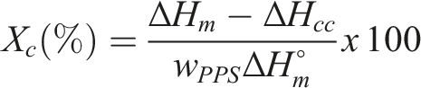
Since PPS is a partially crystalline thermoplastic polymer, it was important to measure crystallinity amount forming during hot press consolidation process. Thus, differential scanning calorimetry (DSC) (TA Instruments, Q100) (Figure 1(a)) analysis was conducted to determine the degree of crystallinity of PPS matrix during consolidation via double cycle heating profile from room temperature to 350°C at a rate of 10°C/min under nitrogen flow by using the following equation
It should be again noted that DSC analysis was used not only after laminate production by hot press consolidation. Since joining of the laminates via film adhesive was achieved in an autoclave system, then it was also important to use DSC analysis to determine and compare the degree of matrix crystallinity “after the joining” process.
Surface treatments of poly(phenylene sulfide)/carbon fiber laminates before joining
In order to improve film adhesive joining of polymer matrix composite parts, their surfaces should be treated with a certain method to activate the bonding mechanisms at the interface. In this study, effects of “plasma” surface treatment were compared with the “untreated” and also with the traditional “grit-blasted” surfaces. These two surface treatments applied onto the PPS/CF laminates were explained below.
Grit-blasting
Grit-blasting is a traditional surface treatment technique still used in the aircraft industry. In this method, grit (also named as sand) abrasive particles are accelerated by compressed air and blasted to the surface with controlled velocity and distance. As shown in Figure 1(b), PPS/CF laminate surfaces were blasted by aluminum oxide particles having average size of 177 μm (#80 mesh). Blasting was applied at an air pressure of 2.7 atm, through 8 mm diameter spray nozzle from a distance of 150 mm, and a projection angle of 45°–60° for 60 s. After grit-blasting, laminate surfaces were cleaned with water spray, and then dried in oven at 60°C for 2 h.
Atmospheric plasma treatment
Since plasma is the ionized gaseous state consisting of positively and negatively charged particles, use of plasma surface treatment is one of the most efficient techniques to chemically activate the surfaces required for all adhesive bonding operations. In this study, atmospheric-pressure plasma system used was Plasmatreat GmbH with a RD2004 model rotating plasma jet nozzle which could be connected to a robotic system (TOYO, HKTM Robots) to operate along x, y and z directions.
In this plasma treatment system (Figure 1(b)), it was possible to use “air” as the plasma gas, on the other hand, “velocity” and “distance” of the plasma jet could be arranged. Therefore, in order to investigate effects of these two plasma parameters on the performance of film adhesive joining, the following three different values for each parameter were studied. • Velocity of the plasma jet (mm/s): 10, 100, 200 • Distance between the plasma nozzle and laminate surface (mm): 11, 15, 20
After plasma treatments, surfaces of the laminates were protected by covering with aluminum foil and the joining process was applied in a period not more than 3 h.
Thermal camera analysis
That analysis during the plasma treatment was conducted in order to observe the degree and the distribution of the temperature on the surfaces of PPS/CF laminates, so that suitable combinations of “velocity” and “distance” parameters of the plasma jet could be selected. For this purpose, temperature mapping of the PPS/CF surfaces during plasma treatment was recorded by FLIR X6580sc model thermal camera (Figure 1(b)) placed approximately 1 m away from the surface. Thermal emissivity value of PPS/CF surfaces required to obtain thermal mapping images was set as 0.90 as reported in the literature. 41
Analyses of surface treated poly (phenylene sulfide)/carbon fiber laminates before joining
As explained below, in order to characterize untreated, grit-blasted and plasma treated PPS/CF laminate surfaces; three basic characterization techniques i.e., surface roughness, wettability, and chemical analyses were conducted.
Surface roughness analysis
Since surface roughness of PPS/CF laminates play a significant role especially on the mechanical bonding mechanism, surface topography of untreated and all treated 2 × 2 cm samples were examined under a contact type MAHR profilometer (Figure 1(c)) stylus recording the vertical displacement as it moves. Then, surface roughness profile of the samples in accordance with ISO 16,610-21 standard was obtained in terms of average roughness R a and R z as the maximum height of the profile. For each sample surface, measurements were taken at least from five different regions.
Wettability analysis (contact angle and surface free energy)
Effects of all surface treatments on the wettability were investigated first of all by Contact Angle measurements in accordance with ASTM D7334 standard via an optical tensiometer (Biolin Scientific, Attention Theta Lite) using 4–5 μL distilled water sessile droplets from five different regions (Figure 1(c)). Angle between the laminate surface and the water droplet was recorded by the camera within 10 s. Then, the contact angle (θ) was determined as the average of images taken in that period (Figure 1(c)).
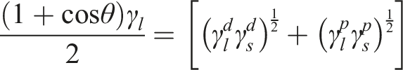
In this study, surface free energies of untreated and all treated laminates were estimated in accordance with ASTM D7490 standard based on Owens-Wendt-Kaelble method. In this method, apart from distilled water, another liquid with known dispersion and polar surface energy components is necessary. For this purpose, diiodomethane was used. Then, using the known dispersive and polar components of both liquids and the contact angles measured, surface free energies could be estimated by the following equation
Total surface tensions (
Chemical analysis (fourier transform infrared spectroscopy and X-ray photoelectron spectroscopy)
Fourier-transform infrared spectroscopy was conducted using Perkin-Elmer Spectrum One® Spectrometer with a universal sampling accessory ATR stage having Diamond/ZnSe crystal (Figure 1(c)). In the infrared spectrum range of 600–4000 cm−1, all treated surfaces were evaluated by comparing with the untreated surface. After backgrounding, a total of 50 scans at 4 cm−1 resolution were averaged for each laminate surface.
Chemistry of the treated PPS/CF laminate surfaces were also examined under an X-ray photoelectron spectrometer (Thermo Fisher Scientific, K-Alpha) (Figure 1(c)). Elemental compositions of the treated surfaces were compared with the untreated one. XPS scanning energy spectrum was processed using the least square fitting software and the C 1s, S 2p and O 1s fine spectra were fitted with peak separation. For the emission of photoelectrons with element-specific binding energies, surfaces were scanned under monochromatic Al-Kα radiation (1486.7 eV).
Joining of poly(phenylene sulfide)/carbon fiber laminates with film adhesive bonding
In this study, joining operations of untreated and all surface treated PPS/CF laminates were performed by using a commercially available epoxy-based film adhesive (Solvay, Cytec FM 300K) with a thickness of 0.2 mm and areal weight of 244 gsm. It is stated that shear strength of this aircraft industry purpose film adhesive at room temperature and 150°C are 35 MPa and 20 MPa, respectively. Due to its thermoset character, shelf-life of this green-colored adhesive film is given as 12 months if cold stored below −18°C.
Steps used during film adhesive joining of PPS/CF laminate samples applied in clean room conditions are illustrated in Figure 1(d). First, green-colored film adhesive was peeled off from the upper and lower carrier films and cut into certain sizes suitable for the laminate samples; then, placed in between the two laminates to be joined (Figure 1(d)).
Since the film adhesive material used was epoxy-based thermoset in the partially-cured flexible state, procedures applied during full-curing play a very significant role to achieve rigid and strong bonding in the joint. Therefore, for this purpose “vacuum bagging in the autoclave” approach was used as described below.
Laminates with film adhesive in between were placed on a tool and covered with a temperature resistant plastic bag having vacuum connections to apply a vacuum pressure of 0.04 bar for compacting the layers. Then, three main full-curing parameters (i.e. temperature = 180°C, pressure = 3 bar, time = 150 min) as advised by the film adhesive supplier were applied in an autoclave system (Figure 1(d)).
After slow cooling (2–3°C/min), film adhesive joined laminates were demolded (Figure 1(d)), and then cut into certain sizes for ultrasonic inspection, DSC analyses, and mechanical testing.
In order to compare effects of grit-blasting and plasma surface treatments applied to PPS/CF laminates on their joining performance bonded with film adhesive, the first technique used was non-destructive ultrasonic inspection of the joined laminates. For the determination of the partial crystallinity degree of PPS matrix, DSC analyses were also conducted. Then, mechanical performance of the joints was compared by conducting the mechanical tests described below.
Mechanical testing of the film adhesive joined specimens
In order to evaluate joining performance of the untreated and all treated PPS/CF laminate samples, three different mechanical tests were conducted to determine and compare their “interlaminar shear strength”, “interlaminar fracture toughness”, and “drop-weight impact toughness” properties in accordance with the testing standards used for aerospace structures. Tests were conducted at laboratory conditions by using 250 kN capacity Instron 5985 Universal Testing system for SLSS and G IC tests. For each specimen group four specimens were tested, and the properties were reported as average values with ± standard deviations.
Single-lap shear strength tests
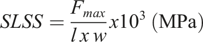
This test was conducted in accordance with ASTM D5868 standard. Figure 1(e) indicates the geometry and the interfacial joined area under shear supplied by tensile load. During the test, “load versus displacement” curves were recorded until the interlaminar shear failure occurred in the joined interface. Then, single-lap shear strength (SLSS) values were calculated by using the following relation
Mode-I interlaminar fracture toughness energy (GIC) tests
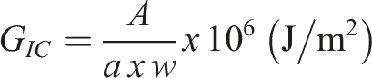
This test was conducted in accordance with the EN 6033 standard. The edge initial crack necessary was introduced by inserting a release film into the interface before the joining operations. Figure 1(e) shows the geometry of the specimen and mode-I loading (opening mode) fixture, where the total length of the specimen was 250 mm while initial crack length i.e. length of the release film was 25 mm. After obtaining “load versus displacement” curves when a total of 100 mm propagated crack length was reached, G
IC
fracture toughness values were calculated by using the following relation
Drop-Weight impact toughness tests
The main purpose of this test conducted in accordance with ASTM D7136 standard is to evaluate resistance of the composite plate specimens against sudden impact loads. Impact damage is imparted by a concentrated impact using a drop-weight with a hemispherical striker tip. In order to impart 50 J impact energy, the mass of the impactor was 8.0 kg, while the diameter of hemispherical striker tip was 16 mm. The impactor was dropped from a height of 635 mm onto the center of joined PPS/CF laminates having 150x100x4 mm plate dimension, which were placed firmly on the support fixture window frame of 125 × 75 mm (Figure 1(e)).
Instron CEAST 9350 Drop Tower Impact test system used records “contact force” versus time data, which could be converted into “absorbed energy” versus time curves. In this study, apart from evaluation of “maximum” values of contact force and absorbed energy (F max and E max ), performance of the laminate specimens was evaluated also by examining the “dept” and “area” of the damages occurred. For this purpose, external damages were inspected by taking their top-view images under visible light and UV light qualitatively. Then, for the quantitative analyses, first of all, dept of the damages were measured with a digital depth indicator (MarCator 1087 BR). Then, for the through-thickness damage area determinations, automated ultrasonic through transmission (AUTT) inspections were conducted.
Results and discussions
Since the main aim of this study was to reveal the degree of the improvement on the film adhesive joining performance of PPS/CF thermoplastic composite laminates when their surfaces were treated by atmospheric plasma technique; plasma treated surfaces were compared with untreated and the traditional grit-blasted surfaces. In the following sections; first, selection of plasma treatment parameters was explained. Then, effects of grit-blasting and plasma treatments were compared in terms of changes on the roughness, wettability and chemistry of the surfaces. Finally, effects of all surface treatments on the joining performance were evaluated by applying three different mechanical tests.
Selection of plasma treatment parameters by thermal camera analysis
It is known that plasma surface treatment is a highly energetic technique leading to certain degree of heat energy developed on the surfaces of the samples. For the thermoplastic matrix composites, the temperature developed during plasma treatment should be much below the glass transition temperature (T g ) of the matrix polymer; which was around 88°C for PPS matrix. Thus, during trials for the selection of the plasma treatment parameters, thermal camera analysis was performed.
Specimen designation and values of the plasma velocity and plasma distance parameters selected for each one; and average values of the surface temperatures recorded by thermal camera.
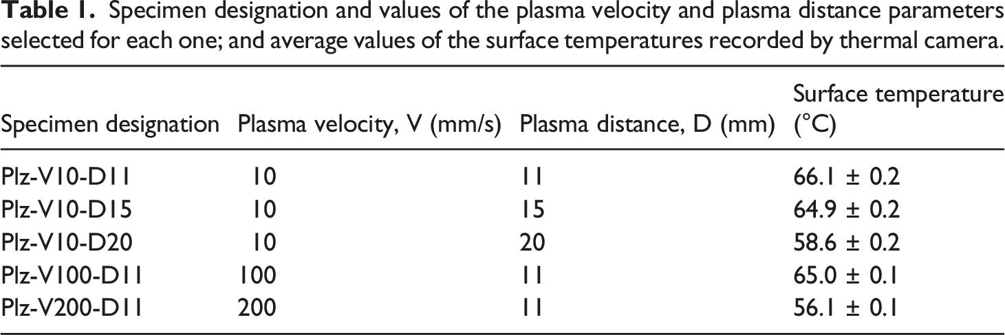
As indicated in Figure 2, surface temperature values during plasma treatments were recorded for the hottest zone (i.e., center of the red colored zone in the temperature mapping) just beneath the nozzle. Then, average values of these temperatures recorded for each specimen type were tabulated in Table 1. It was seen that temperature of the surfaces slightly decreased with increasing plasma velocity and distance. The highest surface temperature developed during plasma treatments was 66°C (for Plz-V10-D11), while the lowest surface temperature developed was 56°C (for Plz-V200-D11). Since these temperatures developed were all well below the T
g
of the PPS matrix, it could be stated that there would be no thermal detrimental effect of plasma treatment parameters selected. Schematics of thermal camera analysis, and an example of temperature mapping image obtained during plasma treatment of PPS/CF surfaces.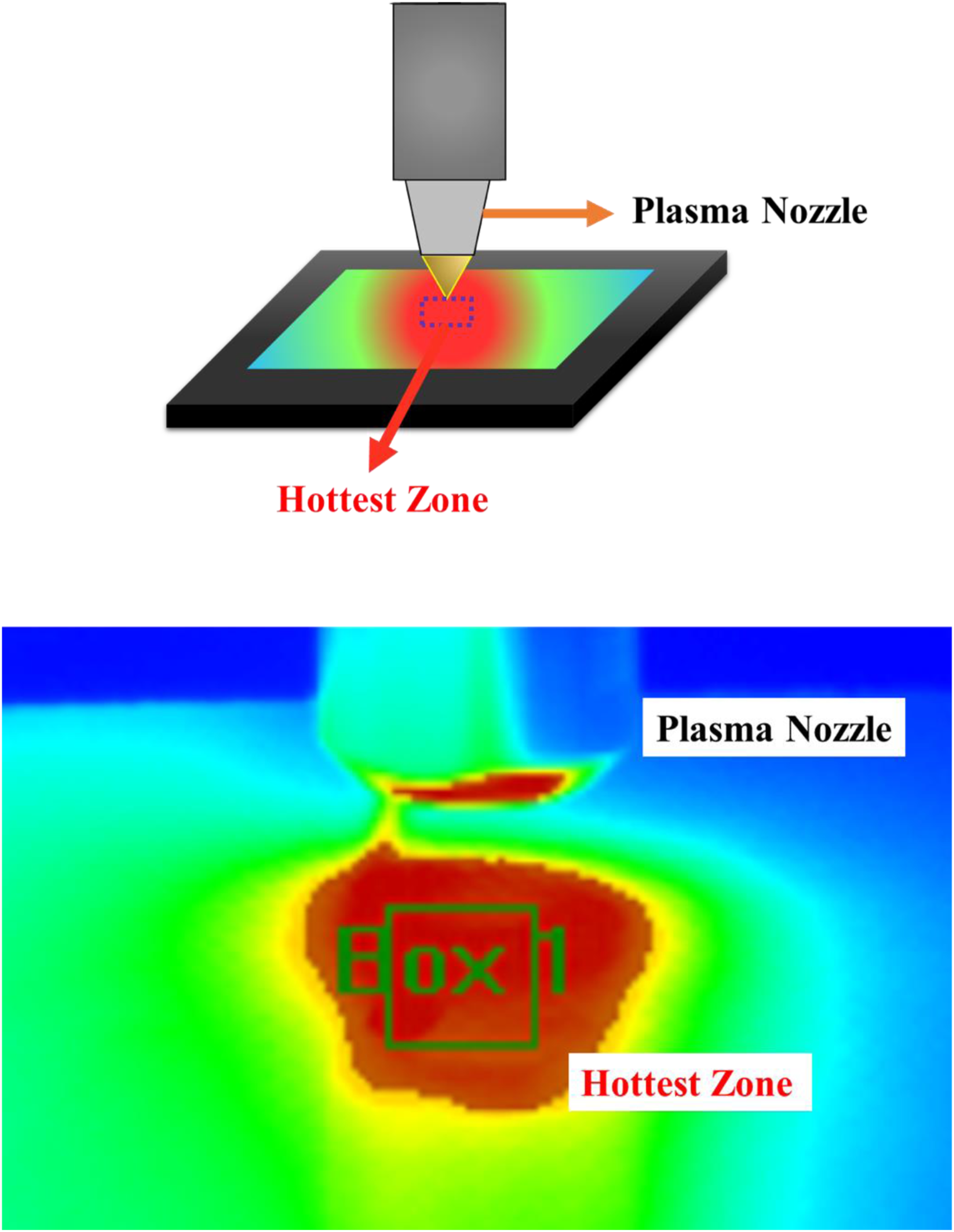
Changes in the roughness of treated poly(phenylene sulfide)/carbon fiber surfaces
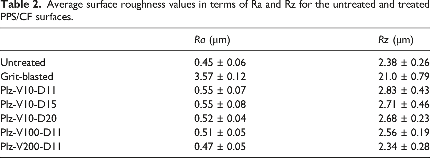
Average surface roughness values in terms of Ra and Rz for the untreated and treated PPS/CF surfaces.
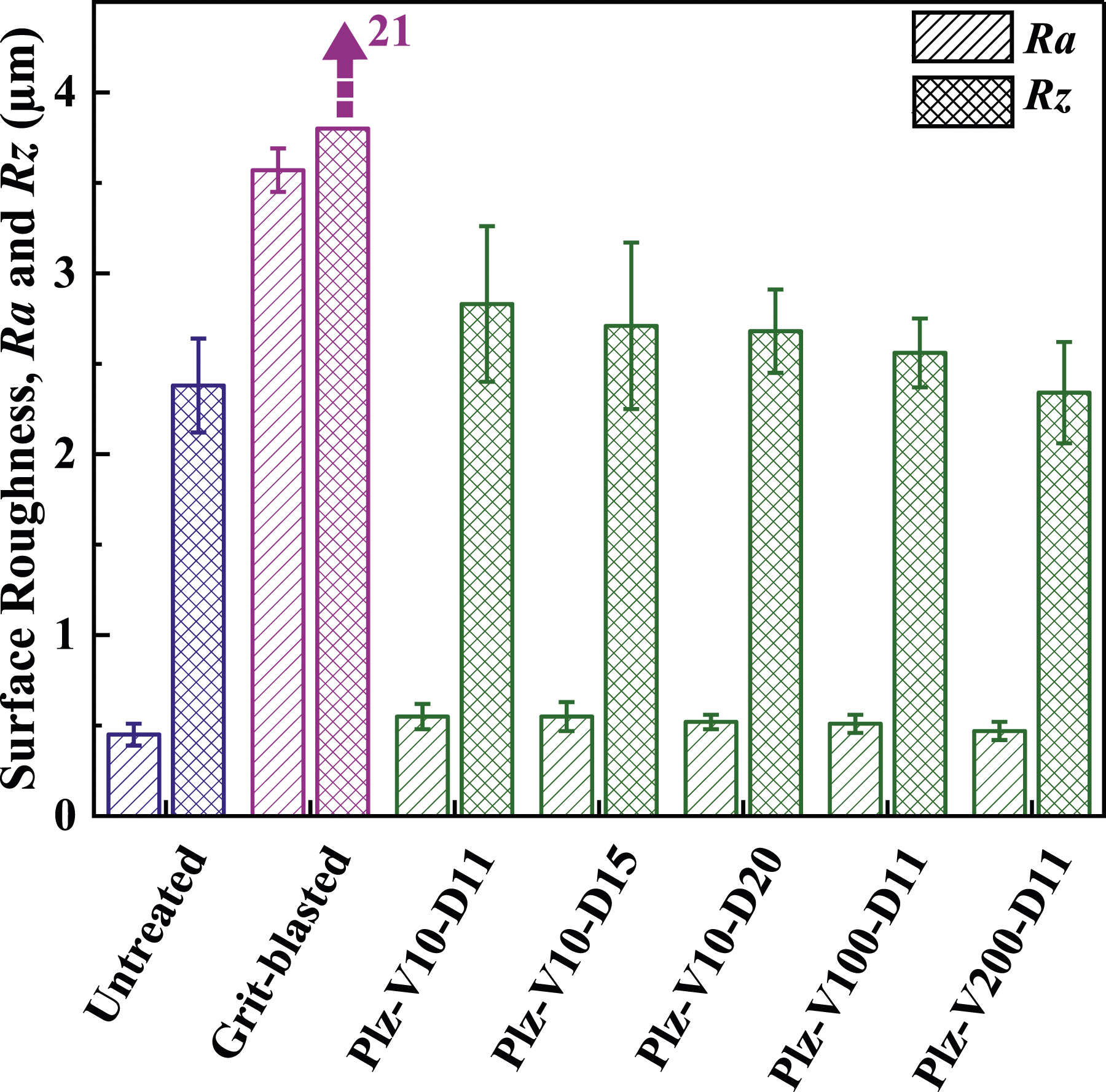
Effects of grit-blasting and plasma treatments on the surface roughness (Ra and Rz) of PPS/CF specimens.
It was seen that after grit-blasting, surface roughness values of the untreated surface increased enormously, the increase in Ra being from 0.45 up to 3.57 μm, while in Rz from 2.38 up to 21.0 μm; that is, increases were more than 7 times and 8 times, respectively. Thus, as would be discussed later, the dominant bonding mechanism in the film adhesive joining of grit-blasted PPS/CF laminates were proposed as mechanical interlocking mechanism.
On the other hand, after plasma treatments, increases in the Ra and Rz surface roughness values were limited, e.g., for the Plz-V10-D11 specimen, these increases were only 22% and 19%, respectively; i.e., from 0.45 to 0.55 μm for Ra, and from 2.38 to 2.83 μm for Rz. Table 2 and Figure 3 also indicated that increasing the plasma velocity and plasma distance parameters resulted in further slight decreases in the Ra and Rz surface roughness values; the lowest values being 0.47 μm for Ra and 2.34 μm for Rz. Thus, as would be discussed later, the dominant mechanism in the film adhesive joining of plasma treated PPS/CF laminates were proposed as chemical interactions between the surfaces.
It was stated in the literature42-46 that the main reason for the slight increases or decreases on the surface roughness values during plasma treatments was the physical and energetic interactions between the positively and negatively charged ionized plasma particles and the atoms or molecules present at the surface.
Changes in the wettability of treated poly(phenylene sulfide)/carbon fiber surfaces
Average values of the water contact angle and total surface free energy including its polar and dispersion components of untreated and treated PPS/CF surfaces.
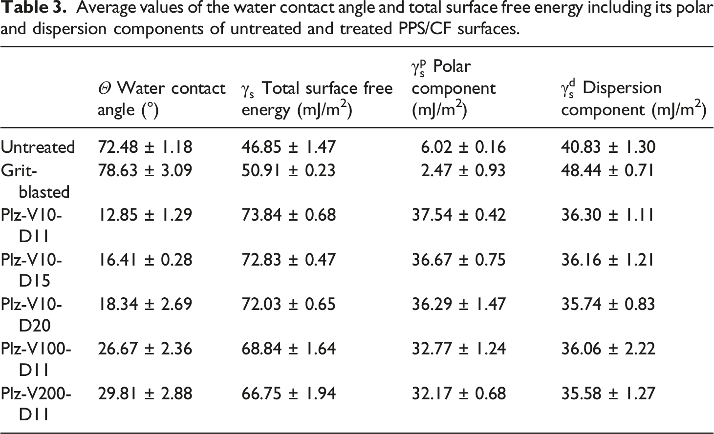
Effects of grit-blasting and plasma treatments on the water contact angle and total surface free energy including its polar and dispersion components of PPS/CF surfaces.
Contact angle
It is known that decreasing the contact angle values increases the spontaneous wetting condition of the surfaces. Table 3 indicated that after grit-blasting, water contact angle value of untreated surface increased slightly from 72.5° to 78.6°. As discussed in the literature,47-49 the reason of these unwanted increases was basically due to the very high level of surface roughness topography with so many numbers of high peaks and narrow valleys preventing the water droplets from penetrating into these extensive number of surface irregularities.
On the other hand, after all plasma treatments, it was seen that there was enormous decrease in the water contact angle value of the untreated surface. For instance, the decrease for the Plz-V10-D11 specimen surface was from 72.5° down to 12.8°, i.e., a decrease of more than 5 times. For the Plz-V200-D11 specimen surface, water contact angle was 29.8°, this time a decrease of more than 2 times.
Surface energy
For the efficient film adhesive joining method, apart from lower contact angle values, surface free energy of the surfaces should be as high as possible. It was seen in Table 3 that total surface free energy of the untreated specimen increased only 8% (i.e., from 46.8 to 50.9 mJ/m2) for the grit-blasted specimen. Contrarily, after all plasma treatments very significant increases were observed, e.g., for Plz-V10-D11 specimen the increase was 57% (up to 73.8 mJ/m2), while for Plz-V200-D11 specimen it was 42% (up to 66.7 mJ/m2).
Figure 4 revealed that grit-blasting increased surface free energy of PPS/CF laminate surfaces, although their water contact angle increased slightly. It was discussed in the literature14,50 that, the reason of increased total surface energy could be due to the increase in the “dispersion component” of the surface energy. Of course, as also pointed out in the literature,51,52 for the joining performance of all adhesive bonding methods, “polar component” of the surface free energy plays a much more significant role. Table 3 revealed that for the untreated and grit-blasted surfaces polar components were extremely low being only 6.0 and 2.5 mJ/m2, respectively. Plasma treatments increased polar component significantly being all above 32 mJ/m2. This could be interpreted that plasma surface treatments applied might lead to certain polar interactions and chemical bonding mechanism between the film adhesive and PPS/CF surfaces.
Changes in the chemistry of treated poly(phenylene sulfide)/carbon fiber surfaces
It is known that joining performance of all adhesive bonding methods could be improved by increasing polar interactions and chemical bonding mechanisms at the interface. Therefore, in order to observe changes in the chemistry of all treated PPS/CF surfaces compared to the untreated one, two different but complementary chemical analyses were conducted: Fourier transform infrared spectroscopy (FTIR) and X-ray photoelectron spectroscopy (XPS).
Fourier transform infrared spectroscopy
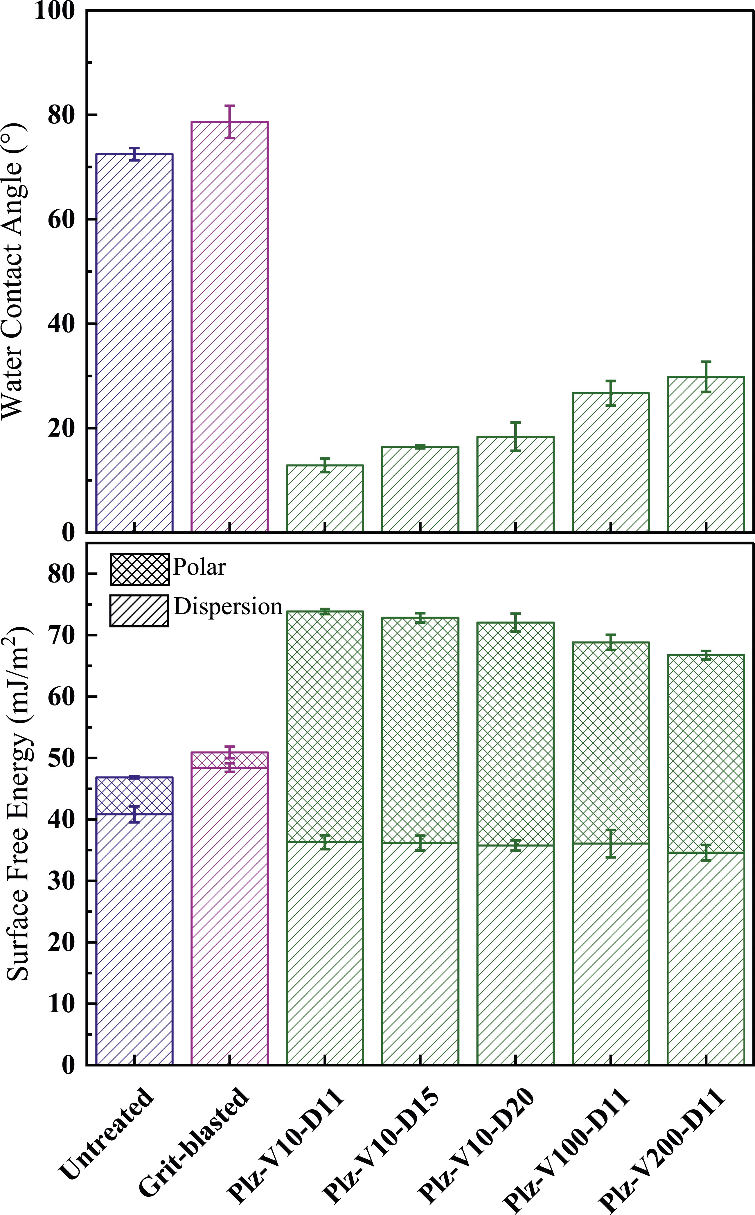
For comparison, FTIR spectra obtained for the untreated, grit-blasted and one of the plasma treated (Plz-V10-D11) surfaces were illustrated in Figure 5. The first spectrum in this figure was for the untreated sample, thus all the characteristic IR peaks attributed for PPS matrix polymer cited in the literature53,54 were observed. That is, peaks at 1573, 1470, and 1384 cm−1 for the stretching vibration of C-C bonds, while 1008 cm−1 for the stretching vibration peak of C = CH in benzene ring. The peak at 1094 cm−1 is attributed to the stretching vibration of the C-S bond and 803 cm−1 corresponds to vibration peak of C-H in benzene ring. FTIR spectra of the untreated, grit-blasted and one of the plasma treated (Plz-V10-D11) PPS/CF surfaces.
Since grit-blasting is rather a mechanical surface treatment changing mainly surface roughness topography, Figure 5 indicated that there were no apparent differences between the spectrum of untreated surface and the spectrum of grit-blasted surface.
On the other hand, Figure 5 revealed that there were certain new IR peaks formed after plasma treatment, such as functional O-H peaks at 3364 cm−1, carbonyl C = O stretching at 1643 cm−1, vibration of C-O at 1286 cm−1, stretching vibrations of -SO2- at 1200 cm−1, and S = O at 1074 cm−1. In the literature,55–57 it was discussed that appearance of these new IR peaks could be due to the oxidative action of the plasma treatment on the PPS polymer structure.
When plasma velocity and distance were increased, it was observed that there were no significant changes in their IR spectra compared to Plz-V10-D11 sample, only intensities of these new peaks were decreased. Thus, it could be pointed out that, formation of these chemically reactive sites (OH, C = O, C-O, -SO2-, S = O) after plasma treatments would improve chemical adhesive bonding mechanism of PPS/CF samples.
X-Ray photoelectron spectroscopy
In Figure 6, XPS spectra obtained for the untreated, grit-blasted and one of the plasma treated (Plz-V10-D11) surfaces were given. It was seen that spectrum of untreated and grit-blasted surfaces were composed of three main elements; carbon (C1 s) at 285.1 eV, sulphur (S 2p) at 164.1 eV, and oxygen (O 1s) at 532.1 eV. Due to the ionized nitrogen species in the air plasma, a tiny peak for nitrogen (N 1s) at 402.1 eV was also appeared for the plasma treated surfaces. XPS spectra of the untreated, grit-blasted and one of the plasma treated (Plz-V10-D11) PPS/CF surfaces.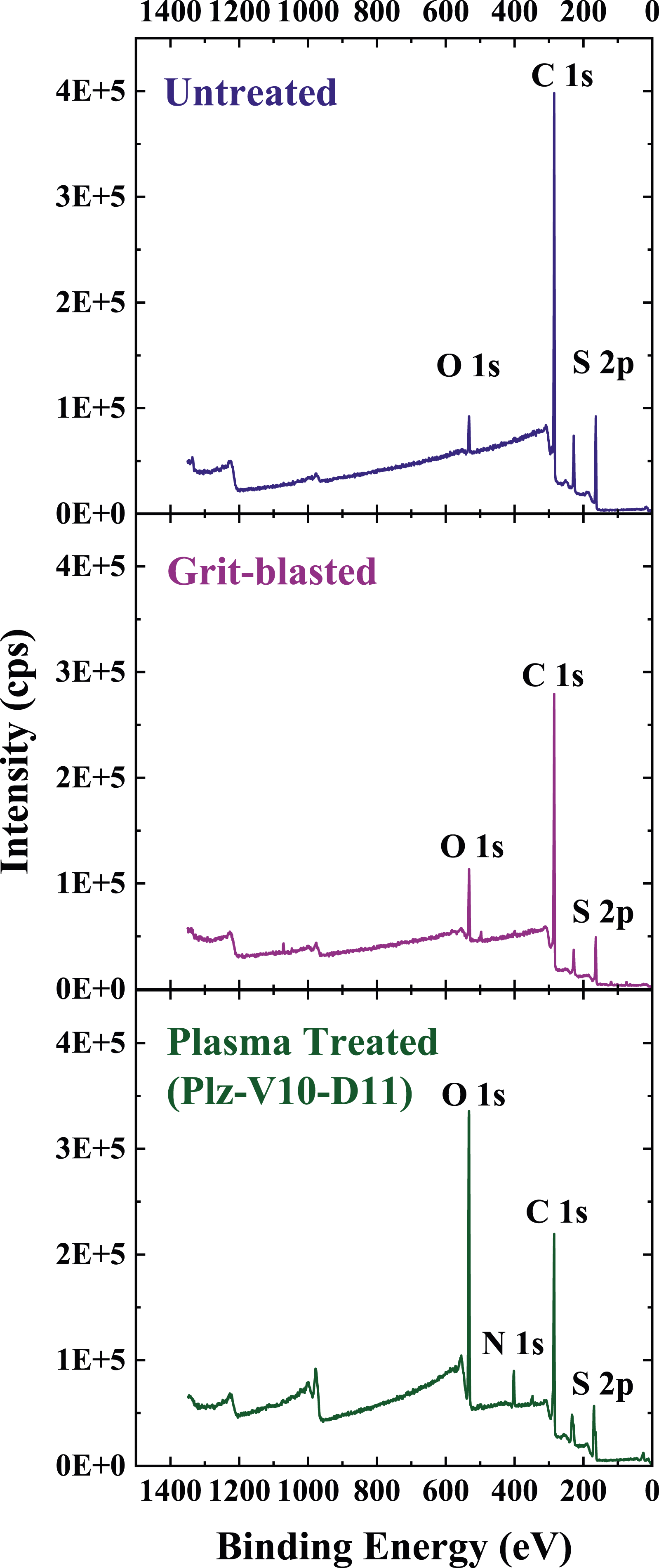
XPS elemental compositions (C, O, S, N) including O/C and O/S atomic ratios of the untreated and treated PPS/CF surfaces.
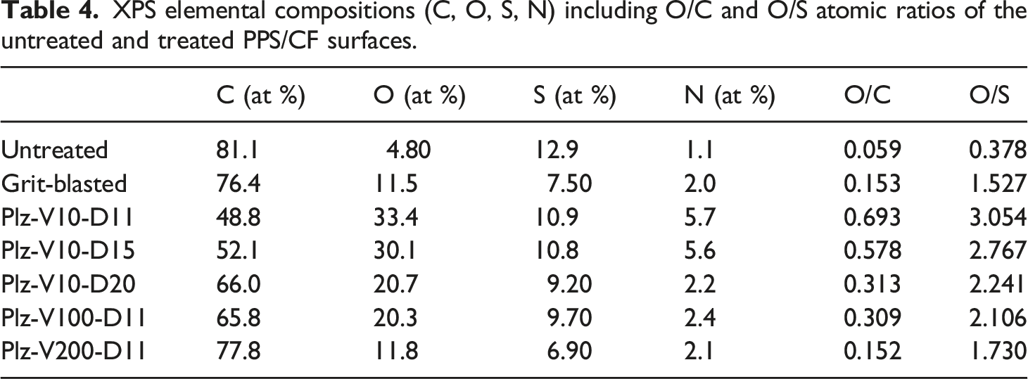
Table 4 indicated that increases in the O/C atomic ratio of untreated surface were from 0.059 to 0.153 after grit-blasting, while it was up to 0.693 after Plz-V10-D11 plasma treatment. Similarly, increases for the O/S atomic ratio was from 0.378 to 1.527 for grit-blasting, while it was up to 3.054 for the Plz-V10-D11 surface.
These very significant increases in the O/C and O/S atomic ratios after plasma treatments could be interpreted that both C and S elements in the PPS matrix polymer were oxidized considerably. Of course, increasing plasma velocity and distance resulted in slight decreases in these atomic ratios.
In Figure 7, in order to reveal these oxidized polar groups on the surfaces of Plz-V10-D11 plasma treated sample, main peaks of C 1s and S 2p were deconvoluted and compared with C 1s and S 2p peaks of untreated surface. It was seen that three new peaks under C 1s envelope appeared which represent formation of the oxidation bonds of C-O at 286.7 eV, C = O at 288.7 eV and O = C-O at 291.3 eV. Likewise, three new peaks were observed under S 2p envelope, indicating the oxidation bonds of S = O at 166.4 eV, O = S = O at 167.4 eV and SO2-OH at 169.9 eV. Similar observations were also cited in the literature.58,59 Deconvoluted forms of the C 1s and S 2p XPS spectra for the untreated sample (above) and Plz-V10-D11 plasma treated sample (below).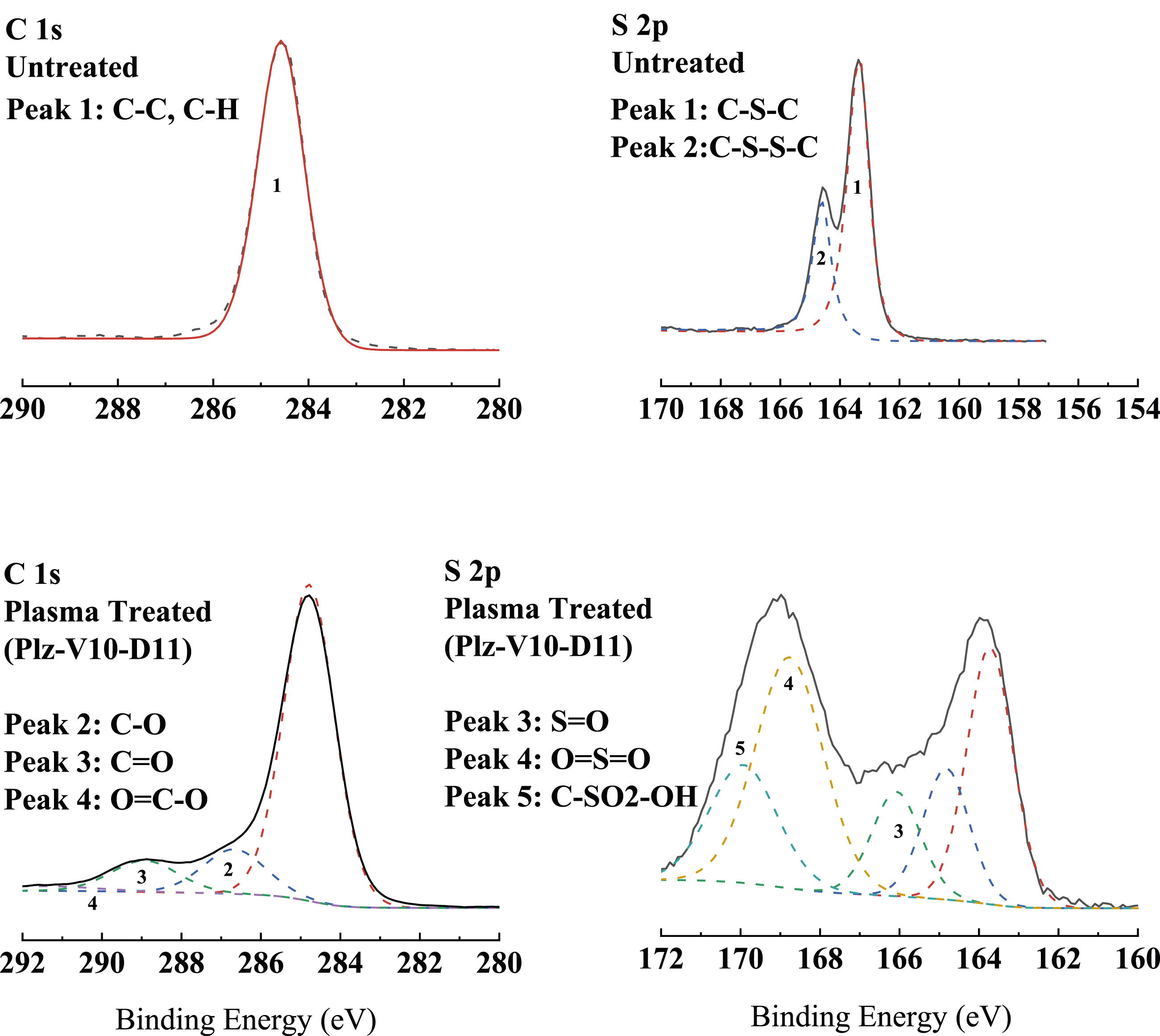
Thus, it could be again stated that, formation of these polar groups, such as C = O, O = C-O and S = O, after plasma treatments would improve film adhesive joining performance of PPS/CF laminate surfaces.
Structural integrity and matrix crystallinity of poly(phenylene sulfide)/carbon fiber laminates before and after joining
In this study, as explained in experimental work section, there were two processing methods used; the first one was “consolidation of prepreg layers” under hot press for the production of PPS/CF laminates, while the second one was “autoclave curing” of the film adhesive layer placed in between the two PPS/CF laminates for joining. Alternatively, in this section, structures obtained after the first process could be named as “before joining”, while the structures obtained after the second process as “after joining”. Thus, it was important to observe structural integrity and matrix crystallinity of PPS/CF laminate structures “before” and “after” joining.
Ultrasonic inspection
In order to reveal whether there was formation of large-scale voids or delamination between the layers, PPS/CF laminates both before and after joining, were inspected by an automated ultrasonic through transmission (AUTT) system. As illustrated in Figure 8, images obtained from this ultrasonic inspection system revealed that there was no significant damage in the PPS/CF laminate structures produced before joining and after joining of untreated, grit-blasted and plasma treated surfaces. Dark regions seen at the edges of the images indicated that there was certain degree of defects formed at the edges of the laminates. However, this was not a problem, because edges of the laminates were all cut during specimen preparation for testing and analyses. Examples of the ultrasonic inspection images of the PPS/CF laminates before and after joining of untreated, grit-blasted and plasma treated surfaces.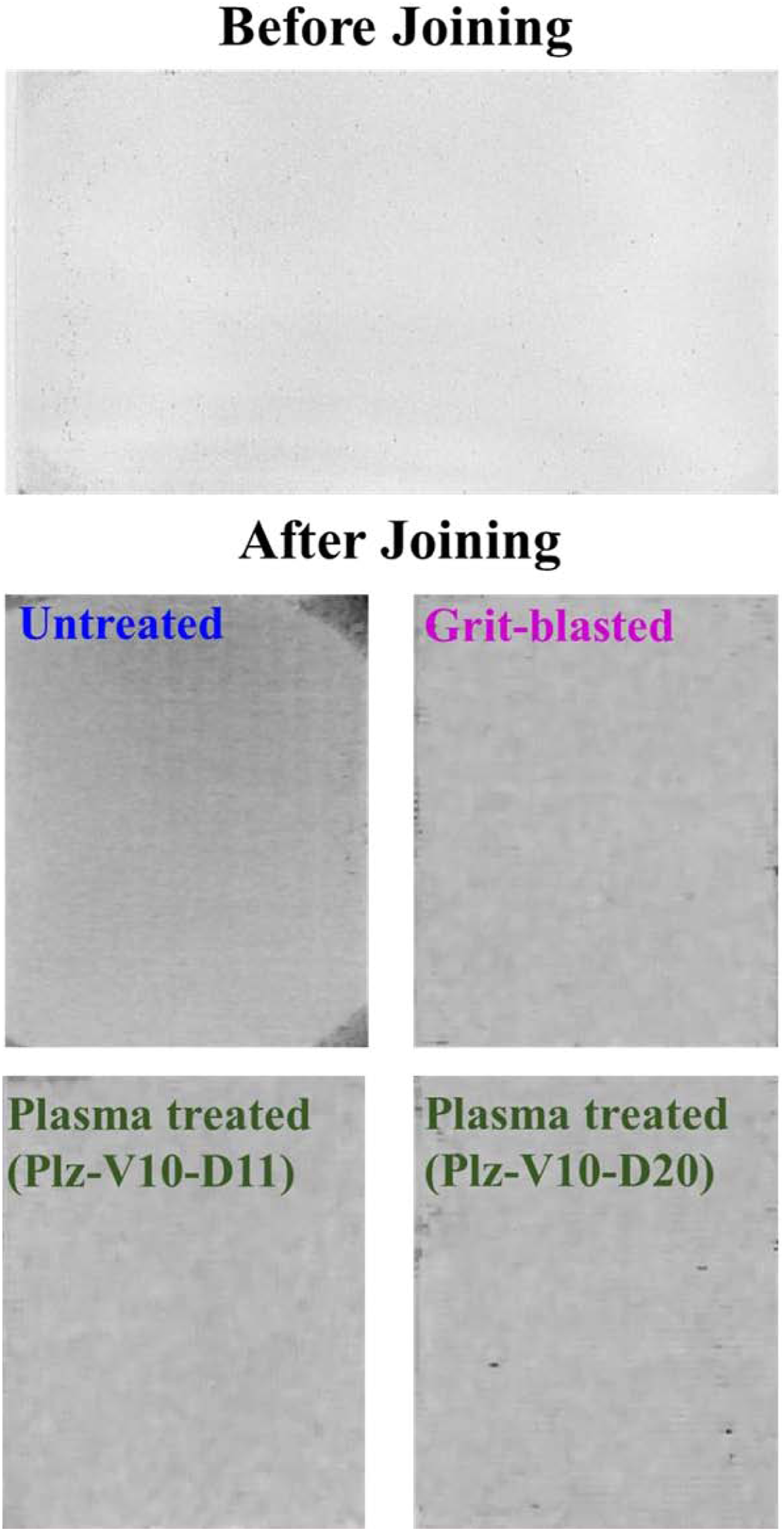
Thus, it could be stated that production of PPS/CF laminates and their film adhesive joining processes were both performed properly, without leading to large scale voids or delamination.
DSC
PPS matrix material of the composite laminates produced in this study was partially crystalline thermoplastic polymer having approximately 30% crystallinity. It is known that amount of crystallinity influences mechanical and thermal performance of thermoplastic polymers. Thus, in order to reveal whether there was significant decrease or not in the crystallinity degree of PPS matrix both before and after joining, DSC analyses were conducted for each case.
As shown in Figure 9, first heating and cooling thermograms of PPS/CF samples before and after joining indicated that values of temperatures for glass transition (T
g
), crystallization (T
c
) and melting (T
m
) were around 88°C, 240°C and 285°C, respectively. First heating and cooling DSC thermograms of PPS/CF samples before and after joining.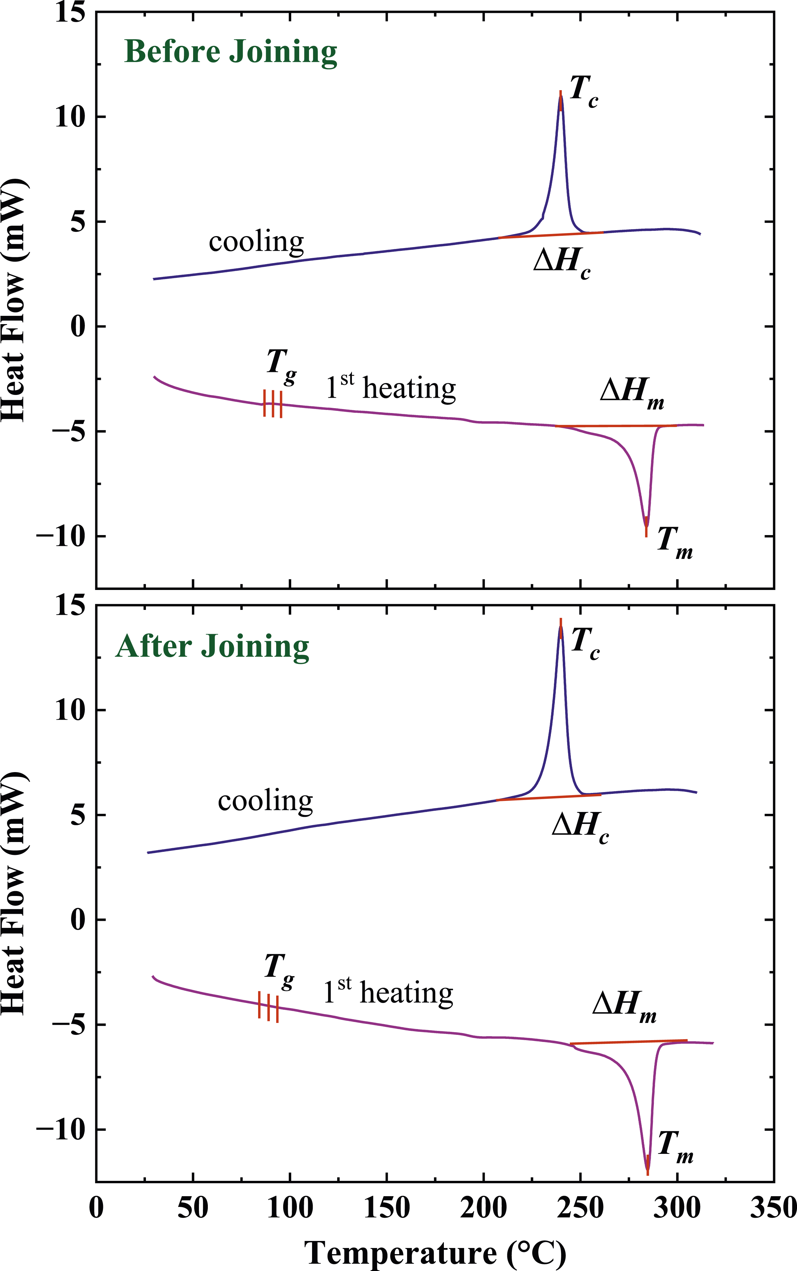
Moreover, during first heating profile no cold crystallization enthalpy (∆H cc ) was observed for each case, which would be interpreted that cooling rates used during these two processes (before and after joining) were sufficient for the crystallization of PPS macromolecular chains. Then, % crystallinity of PPS matrix for each case were determined by using the values of melting enthalpies (∆H m ) only; and it was observed that crystallinity amounts were 28% for both before and after joining.
Thus, it could be pointed out that, heating and cooling parameters used during the production of PPS/CF laminates and their film adhesive joining processes have been both selected properly; leading to both 28% crystallinity, being very close to the expected crystallinity degree of around 30%.
Effects of plasma treatment on the interlaminar shear strength of joined specimens
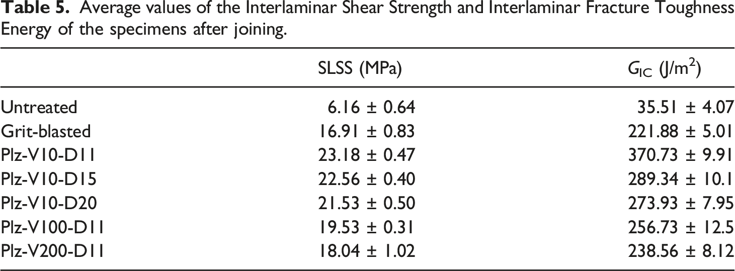
It is known that9,60–62 one of the best testing methods to determine interlaminar shear strength and to observe failure modes of the film adhesive joined composite specimens is single-lap shear strength (SLSS) tests. Thus, after obtaining load-displacement curves of all PPS/CF specimens after joining, their SLSS values were compared in Figure 10 and tabulated in Table 5. At the end, failure mode mechanisms of the specimens were also studied. Load-Displacement curves and SLSS values of the untreated, grit-blasted and plasma treated PPS/CF specimens after joining. Average values of the Interlaminar Shear Strength and Interlaminar Fracture Toughness Energy of the specimens after joining.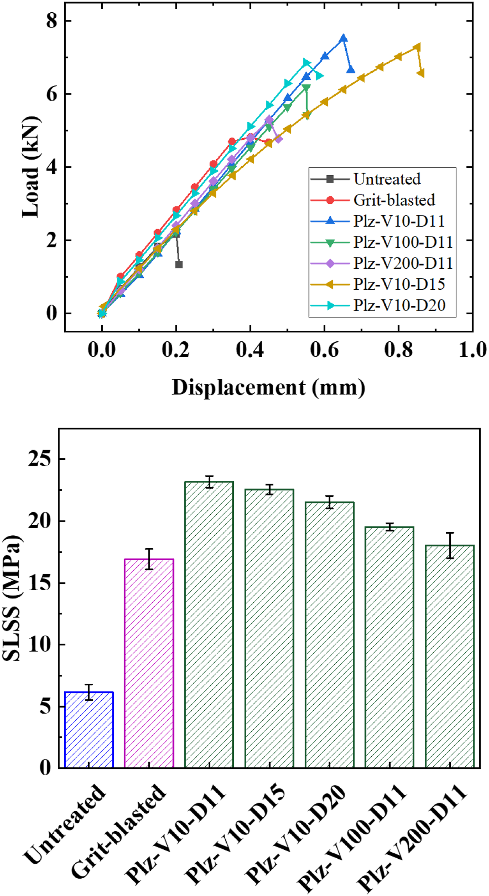
As shown in Figure 10, after grit-blasting, it was observed that SLSS value of untreated specimen increased from 6 MPa to 17 MPa, an increase of almost 3 times. That improvement was mainly due to the increased surface roughness leading to efficient mechanical interlocking mechanism at the interface. This is one of the reasons why that conventional surface treatment is still used in the aircraft industry.
On the other hand, the improvement after plasma treatment was more significant. For instance, for the Plz-V10-D11 specimen SLSS value increased up to 23 MPa, i.e., an increase of almost 4 times. Because, as discussed before, plasma treatment resulted in formation of oxidized functional groups on the surfaces of PPS/CF samples leading to efficient polar interactions and chemical bonding mechanisms at the interface.
Figure 10 also indicated that when velocity and distance parameters of plasma treatment were increased, due to the rather lower chemical interactions, SLSS values of the specimens decreased slightly. However, even the SLSS values of Plz-V10-D20 and Plz-V200-D11 specimens were still above the SLSS value of grit-blasted specimen.
Depending on the joining quality of the film adhesive bonding, interlaminar failure might occur in certain modes. As schematically shown in Figure 11, three typical interlaminar failure modes could be observed: (i) adhesive failure, (ii) cohesive failure, and (iii) mixed failure. Schematics of three typical interlaminar failure modes that could be observed in film adhesive joining method.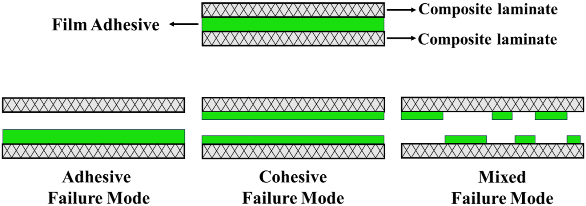
Adhesive failure is the interlaminar failure which takes place between the composite laminate and the film adhesive. It represents the lowest quality of the joining method, mainly due to the absence of any polar interactions or chemical bonding mechanisms at the interface. Thus, as shown in Figure 12, adhesive failure mode was observed for the untreated PPS/CF specimens having the lowest SLSS value. It was clearly seen that green-colored film adhesive material remained on one side of the failure zone, the other side being free of film adhesive. Examples of the three typical interlaminar failure modes observed during SLSS tests.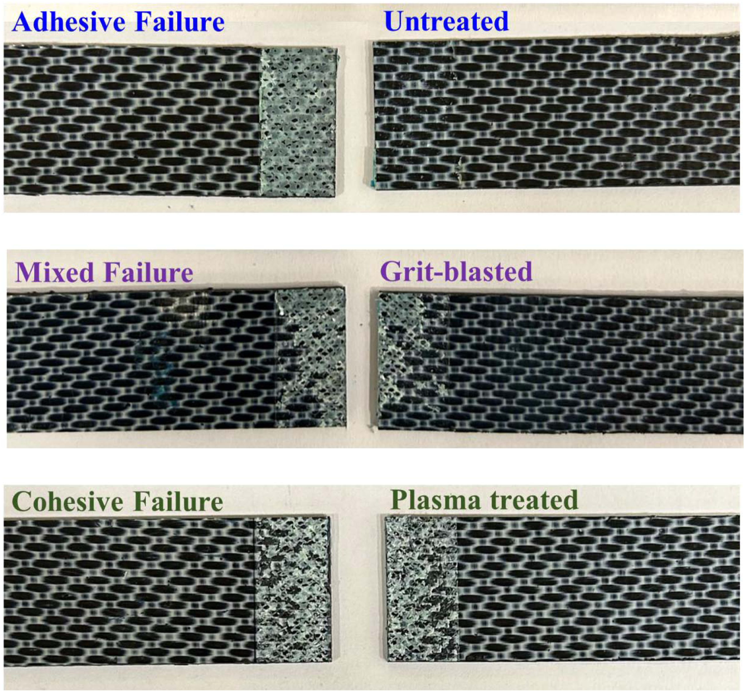
Contrarily, cohesive failure is the interlaminar failure which take place through the film adhesive material itself. It represents the highest quality of the joining method, mainly due to the significant degree of chemical bonding mechanism at the interface. Thus, as shown in Figure 12, cohesive failure mode was only observed in the plasma treated PPS/CF specimens having the highest SLSS values. In this case, green-colored film adhesive material remained on both sides of the failure zone.
Mixed failure could be defined as the mixture of adhesive and cohesive failure modes, i.e. the failure zone takes place partly adhesive and partly cohesive. It represents a moderate quality of the joining method, mainly due to mechanical interlocking mechanism and certain degree of polar interactions at the interface. As shown in Figure 12, this type of mixed failure mode was observed especially for the grit-blasted PPS/CF specimens having moderate level SLSS value. In this case, green-colored film adhesive material remained partly one side and partly on the other side of the failure zone.
Effects of plasma treatment on the interlaminar fracture toughness of joined specimens
Another important mechanical test to determine especially resistance of the bonded interface against crack propagation or delamination is the interlaminar fracture toughness energy under Mode-I, i.e., G
IC
test.21,63,64 Thus, after obtaining load-displacement curves of all PPS/CF specimens after joining, their G
IC
values were compared in Figure 13 and tabulated in Table 5. Load-Displacement curves and G
IC
values of the untreated, grit-blasted and plasma treated PPS/CF specimens after joining.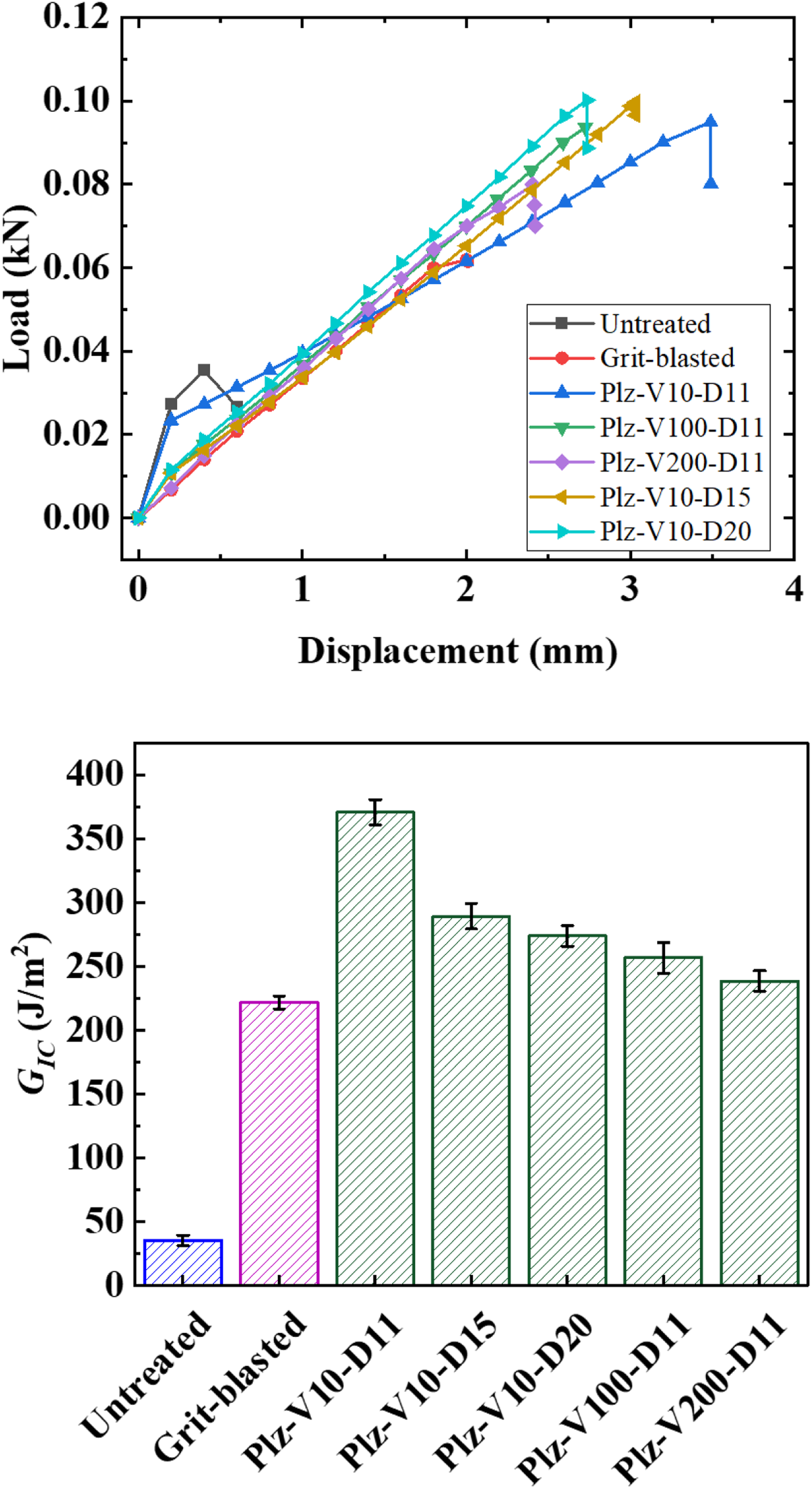
As expected, it was observed that the trends in the results of G IC tests were very similar to the trends in SLSS tests. Because, their bonding mechanisms discussed in the previous section were all the same. For example, after grit-blasting, G IC value of untreated specimen increased form 35 J/m2 to 222 J/m2, an increase of more than 6 times. The increase for the plasma treated (Plz-V10-D11) specimen was up to 371 J/m2, i.e., an increase of more than 10 times. Similarly, increasing the velocity and distance parameters of the plasma treatment resulted in slight decreases in the values of G IC , but still remaining above the G IC value of grit-blasted specimen.
Due to the same bonding mechanisms discussed before, it was revealed that three typical failure modes observed in SLSS tests were almost the same in G
IC
tests. For instance, Figure 14 indicated that adhesive failure occurred again in the untreated specimen, cohesive failure occurred again in the plasma treated specimens, while mixed failure occurred in the grit-blasted specimen. Examples of the three typical interlaminar failure modes observed during G
IC
tests.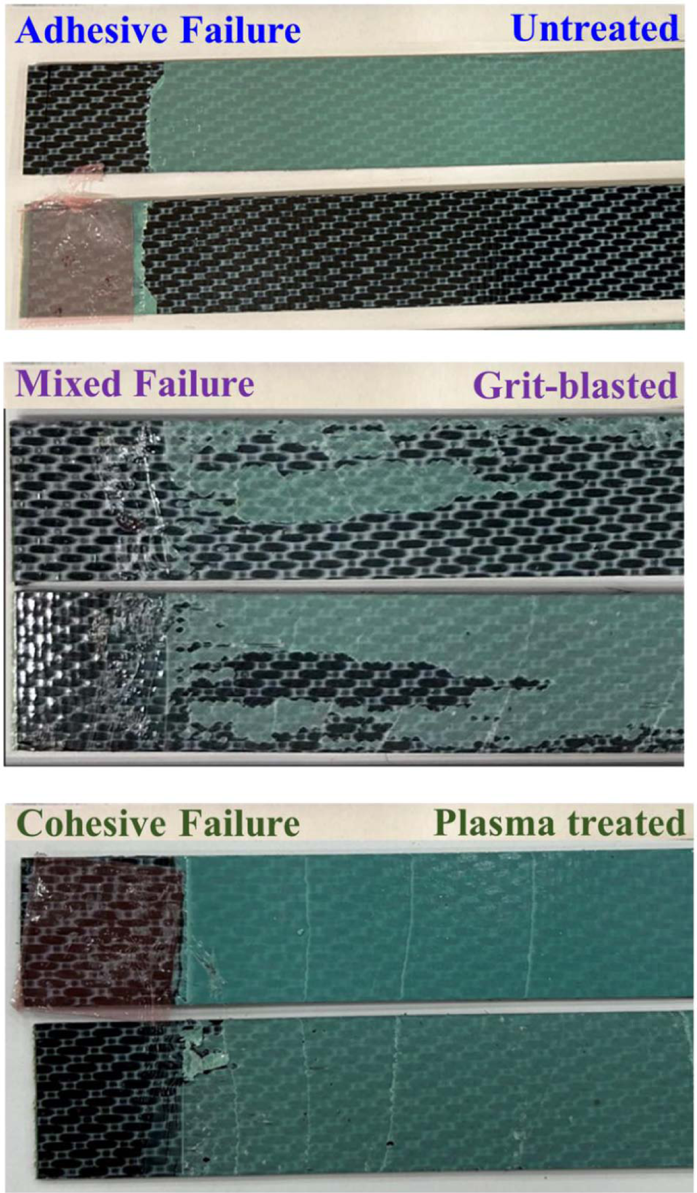
Therefore, it could be generally stated that due to the much higher interlaminar mechanical properties (both SLSS and G IC ) obtained in plasma treated specimens, traditional grit-blasting surface treatment could be replaced with atmospheric plasma surface treatment applied before film adhesive joining of PPS/CF composite parts in aircraft industry.
Effects of plasma treatment on the drop-weight impact toughness of joined specimens
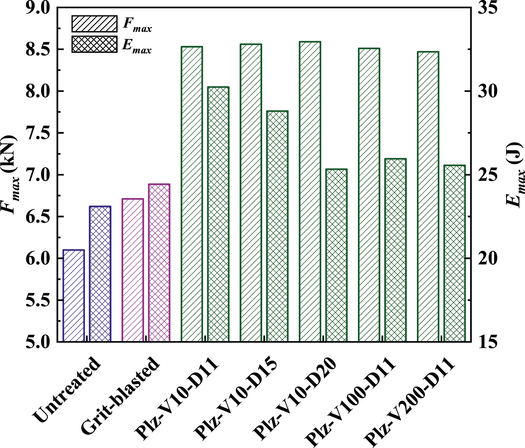
For the composite laminate structures, drop-weight impact test is a common method used to determine their impact toughness energy absorbed and to observe dent and area of the damaged zone. On the other hand, there were very limited studies 65 investigating the performance of composite parts joined by adhesive bonding methods; and none of them were for the PPS/CF laminates. Thus, as the first time in the literature, effects of surface treatments on the film adhesive joining performance of PPS/CF laminates were evaluated by also conducting drop-weight impact test.
During the test, first “contact force versus time” and “absorbed energy versus time” curves were obtained. Examples of these curves were given in Figure 15. Then, maximum values of contact force (F
max
) and absorbed energy (E
max
) after all specimens were compared in Figure 16 and tabulated in Table 6. It was seen that, just like SLSS and G
IC
values discussed before, grit-blasting increased F
max
and E
max
values of the untreated specimen only slightly, whereas plasma treatments resulted in significant increases being all more than 30%. Examples of the Contact Force versus Time and Absorbed Energy versus Time curves obtained during Drop-Weight Impact tests of PPS/CF specimens after joining. Maximum Contact Force (F
max
) and Maximum Absorbed Energy (E
max
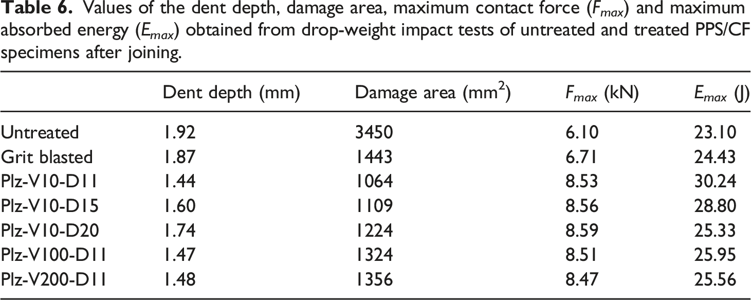
) of the untreated, grit-blasted and plasma treated PPS/CF specimens after Joining. Values of the dent depth, damage area, maximum contact force (F
max
) and maximum absorbed energy (E
max
) obtained from drop-weight impact tests of untreated and treated PPS/CF specimens after joining.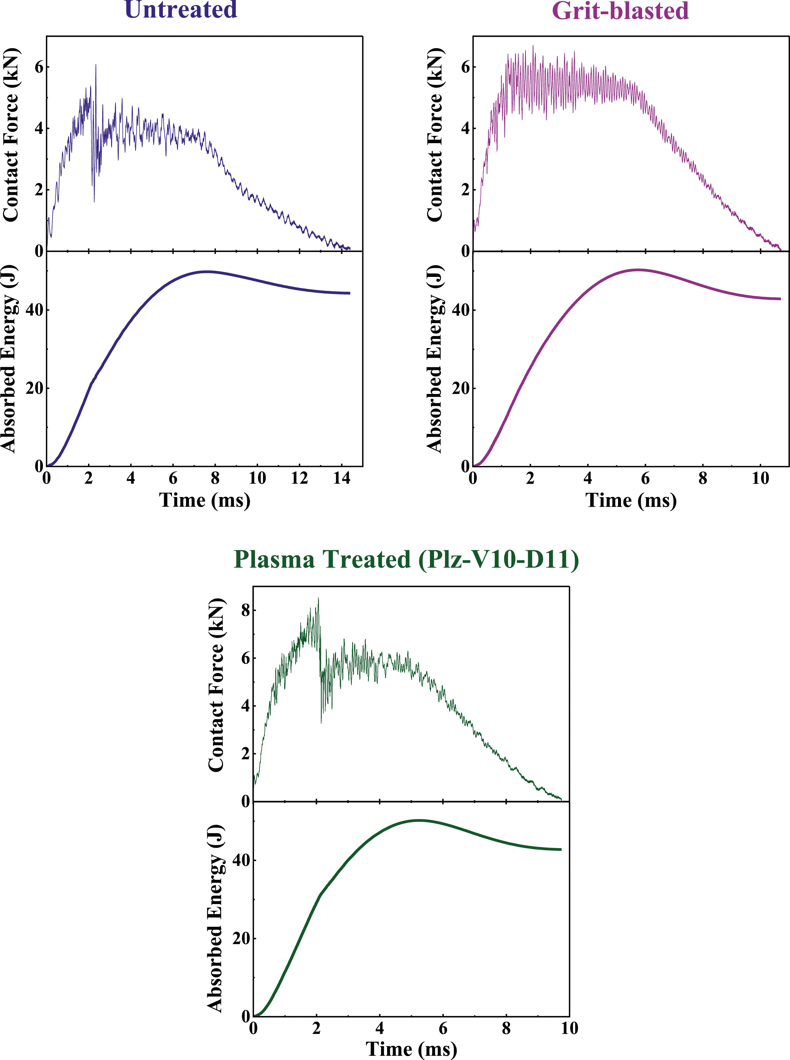
Then, impact toughness performance of all PPS/CF specimens were also evaluated by examining the damaged zone qualitatively and quantitatively. For this purpose, first of all top-view photographic images of all specimens were taken under visible light, then for more clear observation under UV light. Examples of these top-view images given in Figure 17 indicated that impact damage formed in the center of the specimens propagated in other directions mainly through matrix-rich regions. Examples of the Top-View Photographic Images taken under visible light (left) and UV light (right) of the Damage Zones occurred in the drop-weight impact tests of PPS/CF specimens after joining.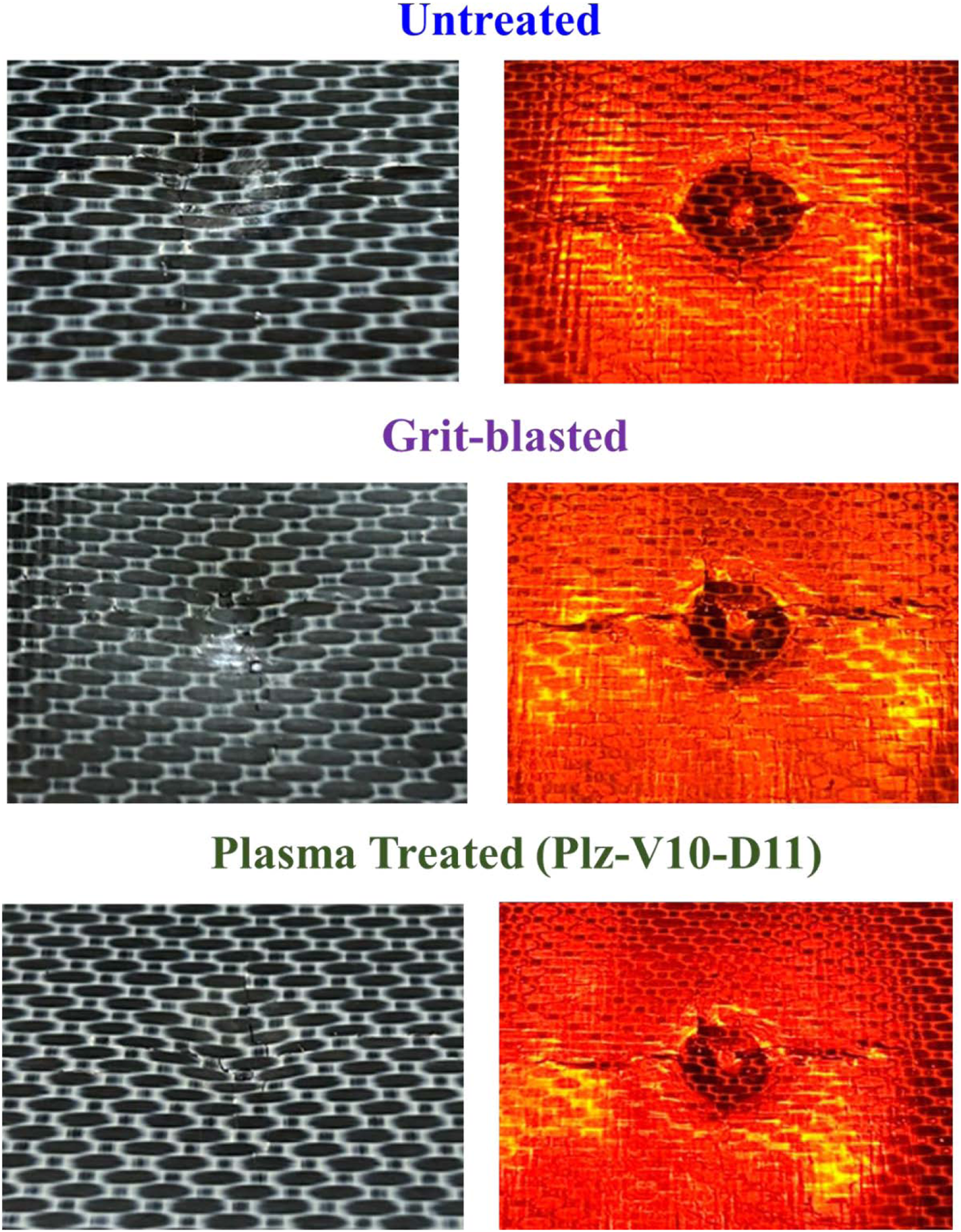
For the quantitative damage analysis, “dent depth” i.e., penetration distance from the surface of the specimens were measured by using a digital dept indicator, and the results in mm were tabulated in Table 6. After that, in order to measure “damage area” not only from the top-view images, but also through the thickness of the specimens; automated ultrasonic through transmission (AUTT) inspection technique was used. Examples of these through-thickness ultrasonic images together with image analysis software views determining the damage area were given in Figure 18. Then, these damage area values in mm2 were also tabulated in Table 6. Examples of the through-thickness Ultrasonic Images together with Image Analyses Software Area determination of the Damage Zones occurred in the drop-weight impact tests of the PPS/CF specimens after joining.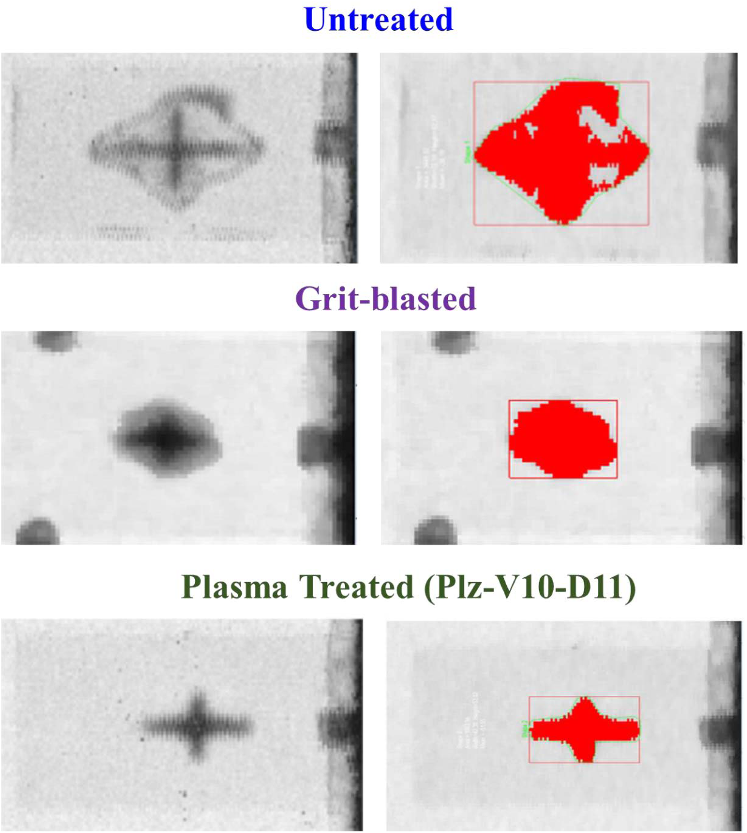
Table 6 revealed that both dent depth and damage area values of the untreated specimens decreased only slightly after grit-blasting. On the other hand, the decreases were more significant after all plasma treatments.
Thus, it could be stated that replacement of grit-blasting with plasma surface treatment would be efficient also in terms of impact toughness performance of film adhesive joined PPS/CF structures.
Conclusions
Main conclusions drawn from the film adhesive joining performance studies for PPS/CF thermoplastic composite laminates could be outlined as follows. • Thermal camera analysis during plasma surface treatments revealed that selected plasma velocity and plasma distance parameters resulted in not more than 66°C surface temperature which was below the T
g
of the PPS matrix; i.e., leading to no detrimental effects. • Profilometer surface topography in terms of Ra and Rz indicated that traditional grit-blasting surface treatment increased surface roughness of the specimens enormously; i.e., the dominant bonding mechanism in the film adhesive joining was mechanical interlocking. • Wettability analysis in terms of contact angle and surface energy, chemical analysis in terms of FTIR and XPS all indicated that plasma surface treatment resulted in formation of chemically reactive sites; i.e., dominant bonding mechanisms in the film adhesive joining were certain polar interactions and chemical bonding. • Before and after the joining process, ultrasonic inspection revealed that there was no formation of large-scale voids or delamination between the layers, while DSC analysis revealed that there was no change in the partial crystallinity amount of the thermoplastic matrix; i.e., it could be stated that production of PPS/CF laminates and their film adhesive joining processes were both performed properly. • Mechanical tests in terms of SLSS, G
IC
and drop-weight impact all pointed out that compared to grit-blasting, plasma surface treatment resulted in considerably higher joint performance regarding interlaminar shear strength, interlaminar fracture toughness and impact toughness values. • It was also observed that adhesive failure mode occurred in the untreated specimen, cohesive failure mode occurred in the plasma treated specimens, while mixed failure mode occurred in the grit-blasted specimen.
Therefore, it could be generally concluded that due to the significant improvement in the joint performance obtained in plasma treated specimens, traditional grit-blasting surface treatment could be replaced with atmospheric plasma surface treatment applied before film adhesive joining of PPS/CF composite parts in aircraft industry.
Footnotes
Declaration of conflicting interests
The author(s) declared no potential conflicts of interest with respect to the research, authorship, and/or publication of this article.
Funding
The author(s) received no financial support for the research, authorship, and/or publication of this article.